Chariots of Fire
-
Posts
2,788 -
Joined
-
Last visited
Content Type
Profiles
Forums
Events
Gallery
Everything posted by Chariots of Fire
-

Build of IH Pumper
Chariots of Fire replied to Chariots of Fire's topic in WIP: Model Trucks: Big Rigs and Heavy Equipment
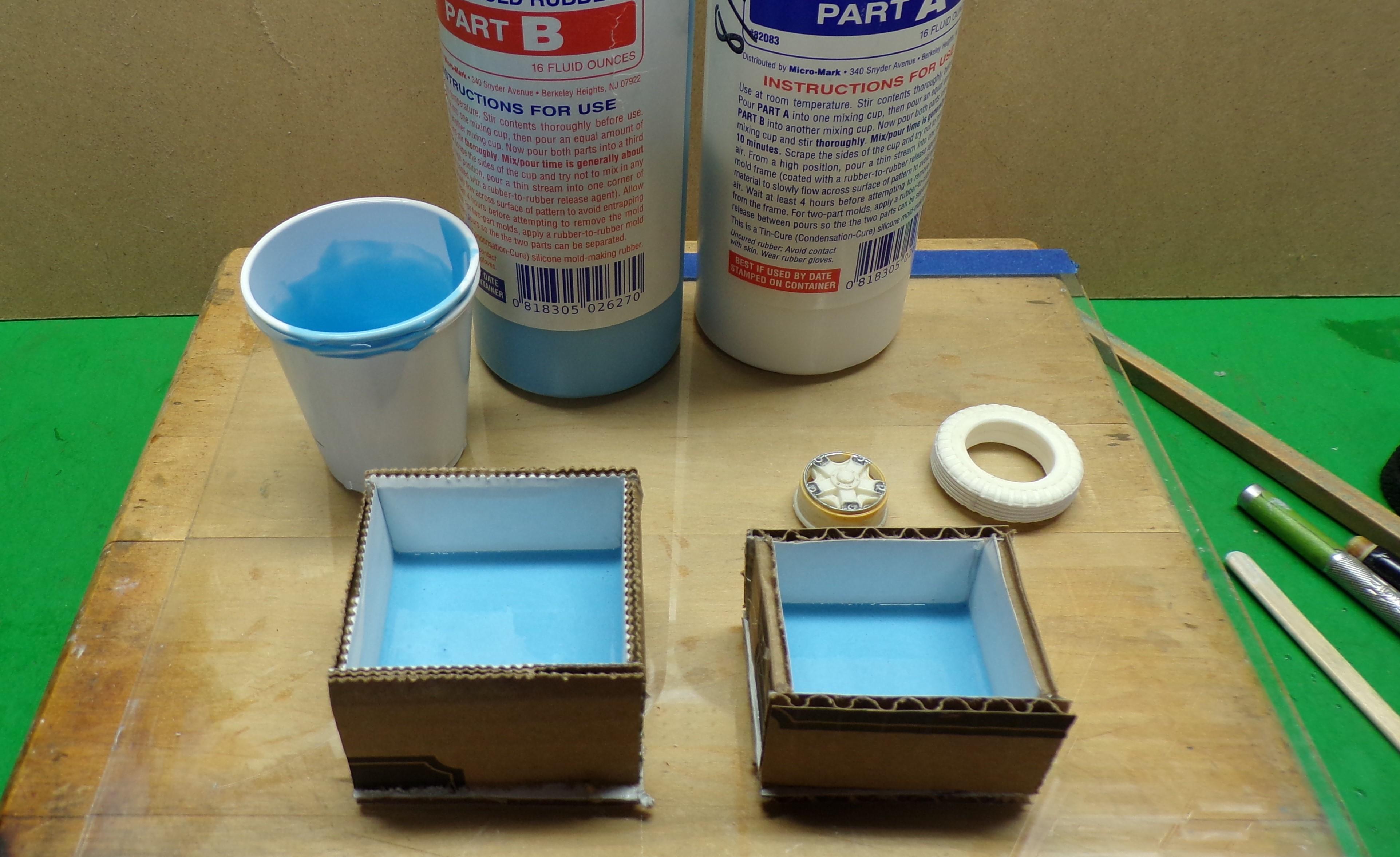
Next up is to get the molds made for the tires and wheels. I cut some cardboard into pieces large enough to leave a 1/4" gap between the tire and inside face of the mold box. Same for the wheel. The pieces are put together using a hot glue gun and a mark was made inside the tire mold box where I want the first pour to go. A wheel mold needs three pours of mold rubber. The first is to fill the bottom of the box up to the line and let it cure. The next pour will include the wheel. The wheel master is inserted into the box after a thin layer of mold rubber is poured on top of the first pour. The rubber needs to coat the bottom surface of the tire completely and sit flat on the mold rubber. Very carefully pour the rest of the liquid rubber around the tire master on the outside only. Do this a little at a time, keeping the tire securely in place so this pour does not get inside the center hole of the tire. Weight it down with a paint bottle or similar weight until this second pour is cured. The second pour is continued until it just rises to the top of the tire but does not spill over onto the sidewall. Once this is done let it cure completely. The mold boxes are ready for the first pour. Note the marks on the two plastic cups. The mold rubber is mixed in 1:1 parts A and B. I mark one cup, insert it inside the second cup to mark it taking into account the thickness of the cup bottom. Use the lines on the cups as a guide for equal amounts of each. The first pours are done and need to cure. When that is done the second pour for the tire and wheel can be done. For the wheel I'll cast it face down. I cut out a circle of masking tape and put it inside the back of the wheel. This will keep the mold rubber from filling the inside of the wheel when it is put into the mold. The tape will be taken out after the second pour is cured.
-
Build of IH Pumper
Chariots of Fire replied to Chariots of Fire's topic in WIP: Model Trucks: Big Rigs and Heavy Equipment
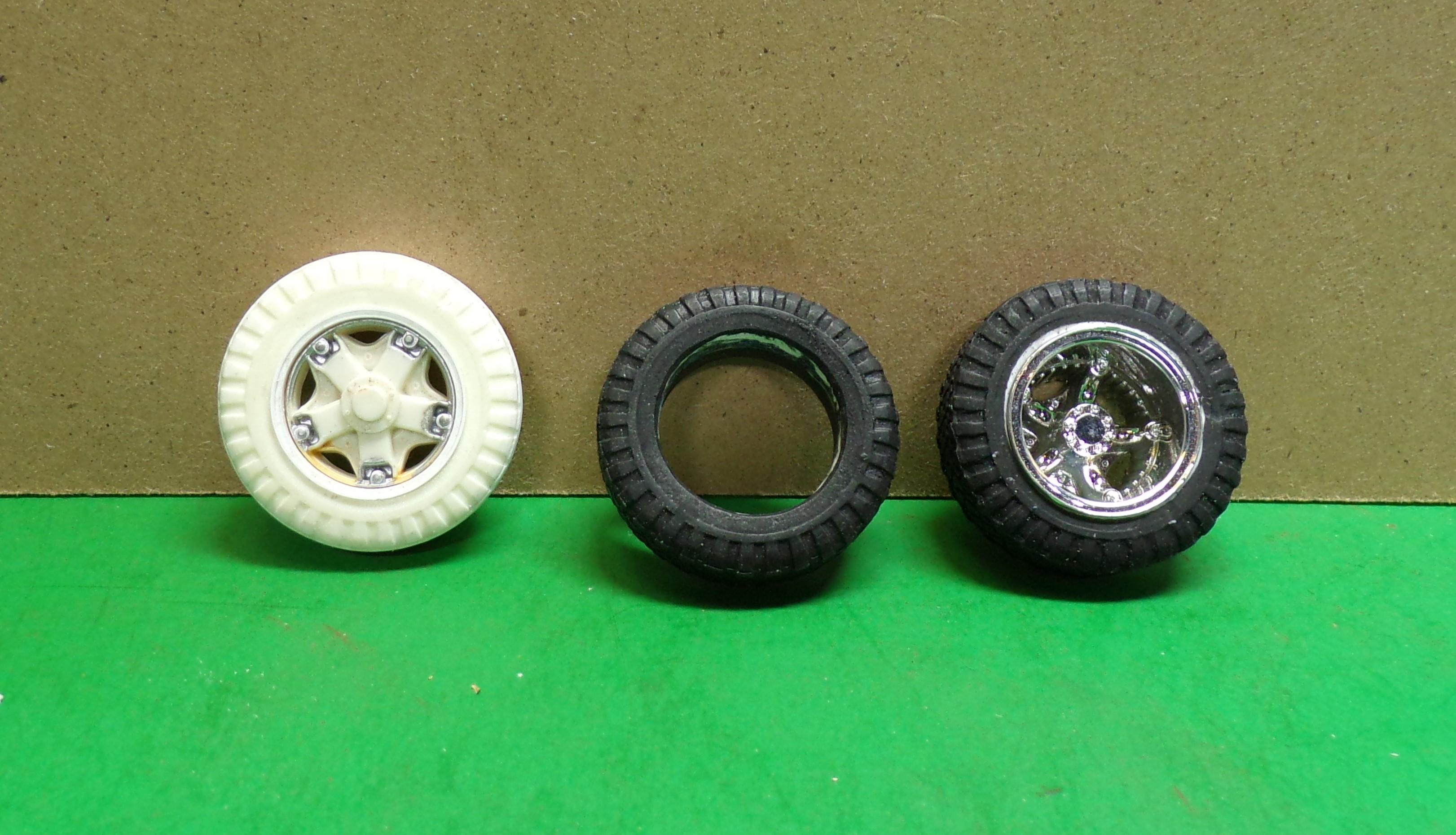
Got a few photos of the materials that I will use in this build. Although it will take on the look of the Chevy pumper, I'm using one of Dave Carey's IH Loadstar cabs and an AMT/Ertl ALF pumper body to start. The IH cab is one piece except for the hood. Included are the floorboard, dash, inside door panels, steering wheel and column, seats and running boards. The ALF body sides are well defined and will go nicely, however the pump panel is going to be made shorter. The long wheelbase doesn't quite cut it. I'll also use the ALF frame although the Ford snowplow frame or even one of the Ertl International frames would work also. This truck is not a big one and I have chosen 37" tall tires and spoke wheels. Years ago I had a tire made and cast of the right size but it has a mud/snow tread design. They are ok for the rear but a standard road tread is best suited for the front unless the idea is to make the rig all wheel drive. In that case the M/S tread is good for the front as well. I chose to put one of the rear tires in my lathe and turn the tread pattern down. To get it back to the right diameter I added a strip of 0.020 by 0.250 plastic strip stock to the tread area. Then I cut grooves in the plastic while it was still on the lathe. Not perfect but the idea is there. Now I will have to make a mold and cast two front tires and also a couple of front rims. I only have one right now and that will be the master for getting two more. The mold making and casting process will be part of this build. The front tire is on the left, a blank rear in the center and the proposed rear rims on the right. The front rim will be cast separate from the tire. More to come.
-
Build of IH Pumper
Chariots of Fire replied to Chariots of Fire's topic in WIP: Model Trucks: Big Rigs and Heavy Equipment
HI, Dom. I have done much of the same as you; utilizing kit parts as masters. Warning lights and bezels are not that hard to do if you have a good source for the master. The Trumpeter ALF kit has numerous bezels and lenses that can be used that way. Also check for things like the light bar that was with the Jeep Honcho kit. I think there were lenses for the lights. Even the 1/32 scale Monogram Mack CF kits can be used to effect. If you have an extra one you might be able to cut out the tail light bezels and cast them as well as the headlights, although the latter would be small for 1/25 scale use. Lenses are easy to cast once you have a good master to copy. I have clear casting resin that mixes 1:1 parts A and B. It's made by Teexpert. Got it on Amazon. The mold material comes from Micro-Mark and is the 1:1 Rapid Cure rubber that they sell. It's not cheap but it picks up every detail nicely. The clear resin seems to stay clear but it takes 24-48 hours to set completely. Simple molds can be made by gluing the master to a flat piece of plastic or card stock and then building a wall around it with similar material. You need to use mold release also so that the resin that you pour in does not stick to the mold. This only works for a part that does not have an under cut. If it does a two part mold may be the better choice. Tires and engine parts are some of the things I have done with both a flat surface mold and a two part mold. I will include a how-to as part of this build. -
Build of IH Pumper
Chariots of Fire replied to Chariots of Fire's topic in WIP: Model Trucks: Big Rigs and Heavy Equipment
Got some pics taken of some of the parts that I'm collecting for the build. Will post one or two as soon as I can. Have some front tires to make up for it first. -
Build of IH Pumper
Chariots of Fire replied to Chariots of Fire's topic in WIP: Model Trucks: Big Rigs and Heavy Equipment
I'll include that, Brian. There's plenty of treadplate on the back of the rig. Not all has to be foil but for some areas it is perfect. -
Ford LS Rescue truck
Chariots of Fire replied to gotnitro?'s topic in WIP: Model Trucks: Big Rigs and Heavy Equipment
Do it with a series of drills. Small at the center and then build out. The final opening can be done with a rat tail file. -
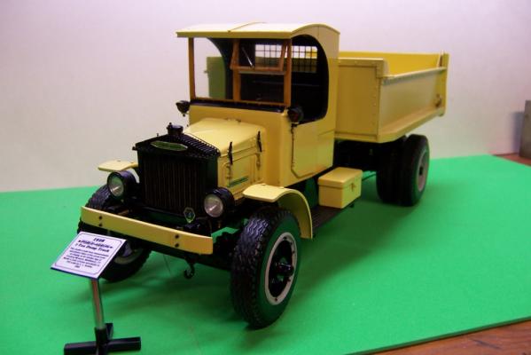
I have a new project in mind that is based on a simple Chevy C70 fire engine that is not far from home. But I'm going to substitute an International Loadstar cab that Dave Carey cast. The idea behind this project is to make it a "how to" using basic techniques and tools. The emphasis will be on clean building, careful alignment and scale. If any of you that do occasional scratch or kit bash work have any ideas you want explored please feel free to speak up. There will be no brass work in this build. Strictly plastic and a bit of resin. Here is the real truck that I will be basing the project on.
-
Ford LS Rescue truck
Chariots of Fire replied to gotnitro?'s topic in WIP: Model Trucks: Big Rigs and Heavy Equipment
DonMillsHobbies also still has them although they may not be plated. But a Molotow pen would take care of that. -
Ford LS Rescue truck
Chariots of Fire replied to gotnitro?'s topic in WIP: Model Trucks: Big Rigs and Heavy Equipment
"Slime" green; probably the most difficult color to keep clean and looking good. Was quite a fad back in the day with some"experts' saying it was for better visibility. Today lots of rigs are back to some scheme of black over red, white over red or just plain red but with lights and strobes everywhere! And thrown in for good measure are diagonal reflective yellow stripes all over the back.☺️ -
BIG Iron
Chariots of Fire replied to Biggu's topic in WIP: Model Trucks: Big Rigs and Heavy Equipment
I see lots of nuts and bolts!😎 -
Diamond T 980
Chariots of Fire replied to The Brush's topic in Model Trucks: Big Rigs and Heavy Equipment
Don't know how I missed this build but I did! Fantastic work! Now I know that at least two 980's exist! -
Western Star 4900 FA plow truck
Chariots of Fire replied to BK9300's topic in WIP: Model Trucks: Big Rigs and Heavy Equipment
Matt Leese does a lot of 3D printing. U-joints come it a variety of sizes depending on your needs. His email address is mdlbldrmatt135@gmail.com Give him a shout. Good guy to deal with. -
Western Star 4900 FA plow truck
Chariots of Fire replied to BK9300's topic in WIP: Model Trucks: Big Rigs and Heavy Equipment
Brian: I got some of those U-joints in 3D form a while ago. Neat stuff. If you need a reference let me know. -
Western Star 4900 FA plow truck
Chariots of Fire replied to BK9300's topic in WIP: Model Trucks: Big Rigs and Heavy Equipment
Never thought I would say this but it may be time for me to assess 3D design and printing! Scratch building is such fun but enhancing it with nicely detailed parts is over the top! -
1941 Autocar U60
Chariots of Fire replied to RoninUtah's topic in WIP: Model Trucks: Big Rigs and Heavy Equipment
Looking to see this for sure. I did the earlier Autocar cab as a WW II piece. Cool looking trucks.
-
BIG Iron
Chariots of Fire replied to Biggu's topic in WIP: Model Trucks: Big Rigs and Heavy Equipment
Those bolt heads will show up in the paint if you do nice thin coats. Some highlighting and/or washes will also bring them out. -
Cat D-7 is finished.
Chariots of Fire replied to Chariots of Fire's topic in Model Trucks: Big Rigs and Heavy Equipment
First time ever building a 3D printed kit. The fit was perfect and the printed detail was superb. It was so smooth no sanding was necessary. -
Cat D-7 is finished.
Chariots of Fire replied to Chariots of Fire's topic in Model Trucks: Big Rigs and Heavy Equipment
Thanks for the comments, guys. Much appreciated. On to the next build!! -
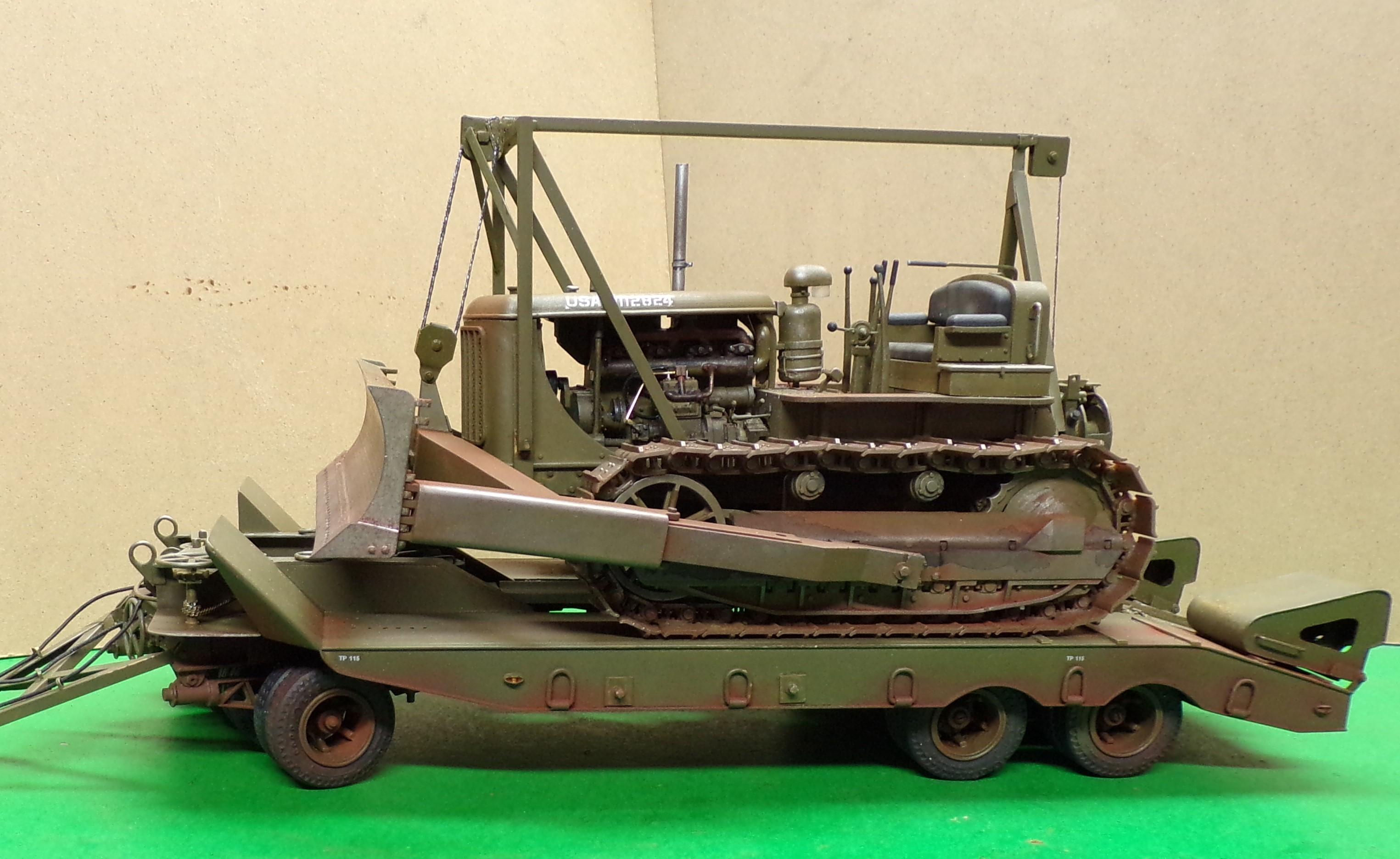
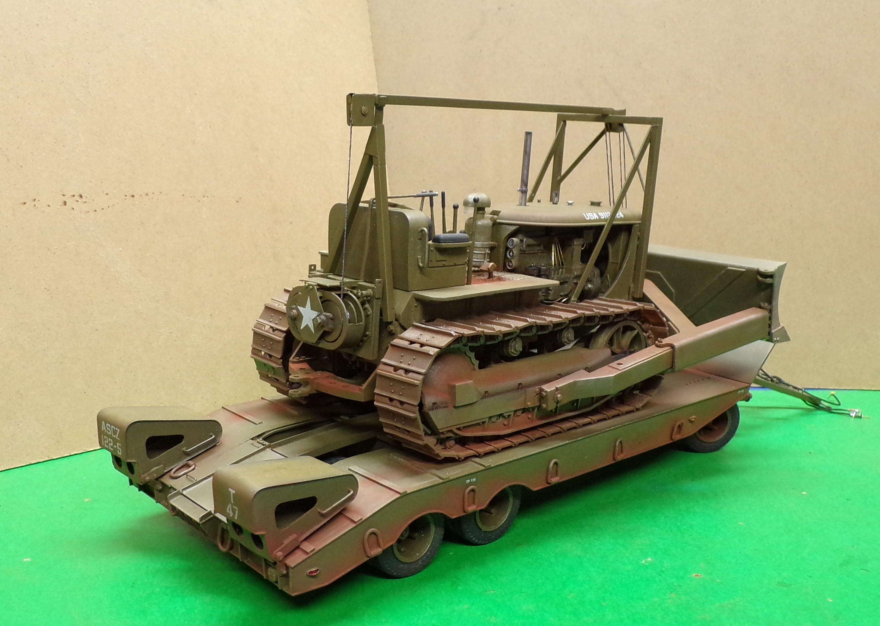
It's now loaded up and ready to travel. The cable guides and pulleys were completed and painted and some decals were added. A little of that red dust was applied as well. Got to go shag down the M-20 and get it moving!
-
Making Tracks
Chariots of Fire replied to Chariots of Fire's topic in WIP: Model Trucks: Big Rigs and Heavy Equipment
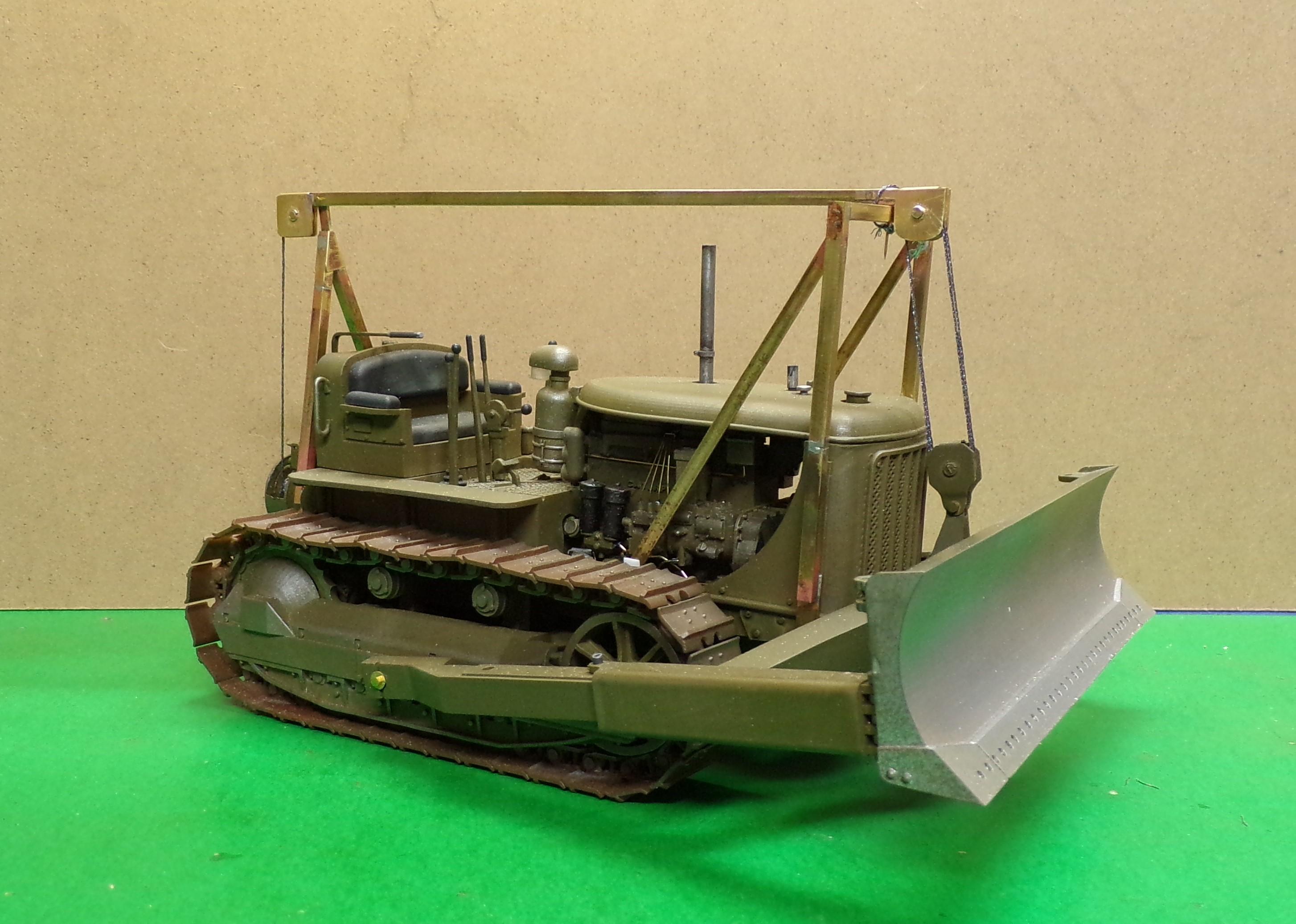
Got the cable frame designed and put together. Some metallic embroidery thread was wound around the control unit drum and then up through the pulleys and frame to the blade pulleys. I tried my special "winding tool" and shazzam! The cable lifted the blade and it stayed up when I released the operating handle. Sometimes things go right. Now I just have to take it all down and paint it and then put it all back together. 😁
-
Brockway 260 Dump
Chariots of Fire replied to Warren D's topic in Model Trucks: Big Rigs and Heavy Equipment
That's a nice conversion, Warren! Well done! -
Making Tracks
Chariots of Fire replied to Chariots of Fire's topic in WIP: Model Trucks: Big Rigs and Heavy Equipment
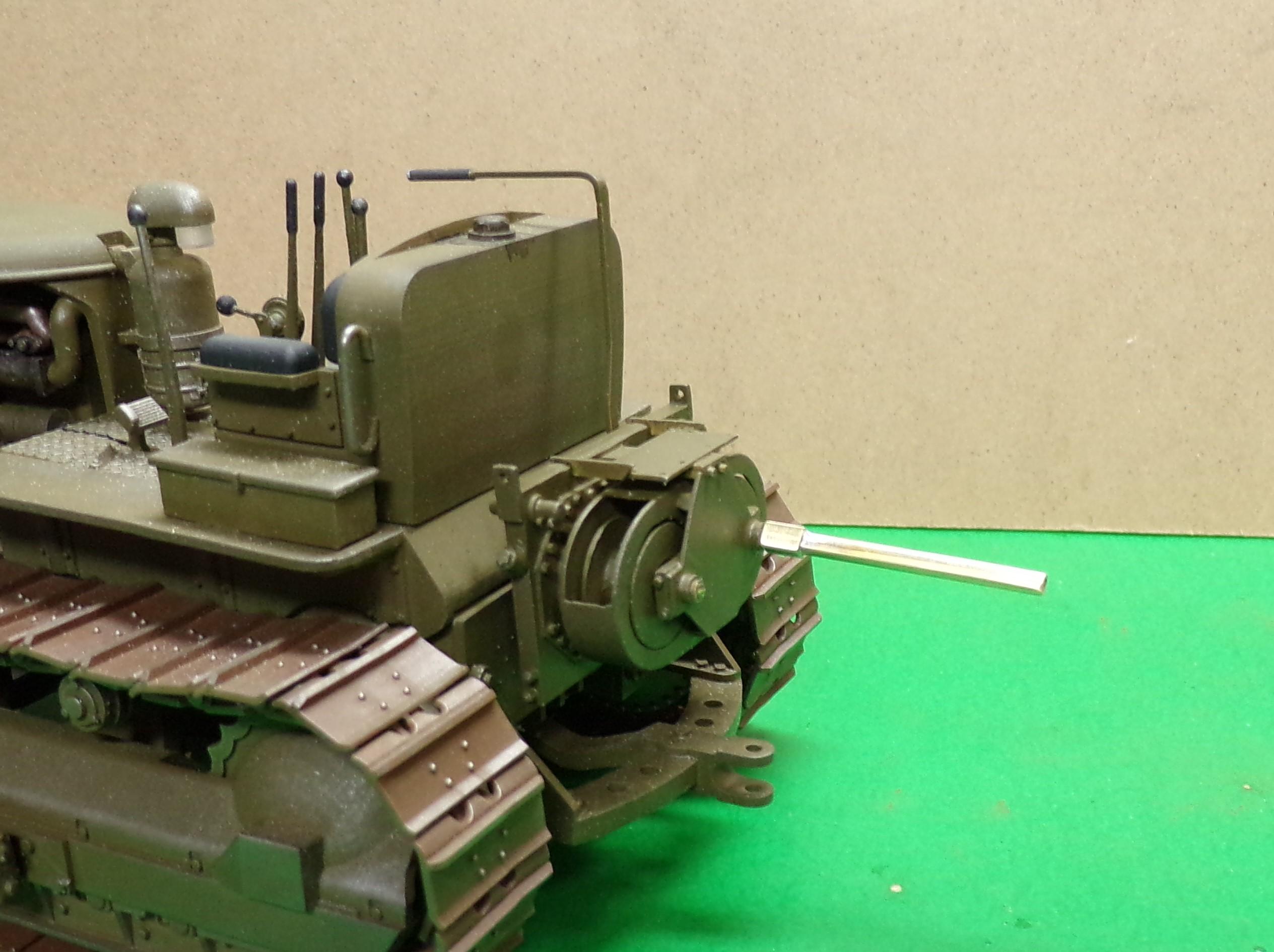
Here's the tool for turning the winch drum. Not very sophisticated but it will work. Two pieces of square tubing soldered together.
-
Making Tracks
Chariots of Fire replied to Chariots of Fire's topic in WIP: Model Trucks: Big Rigs and Heavy Equipment
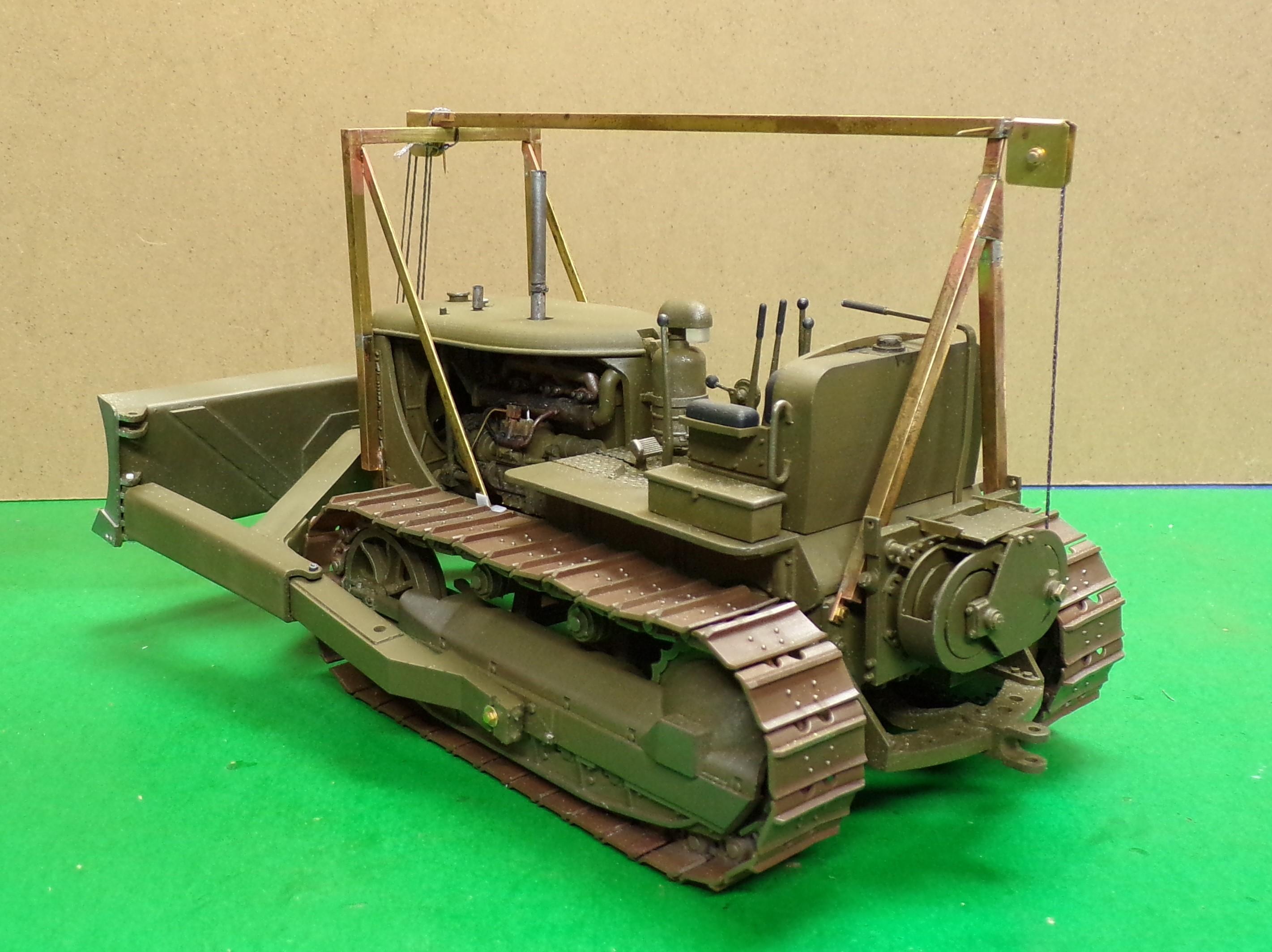
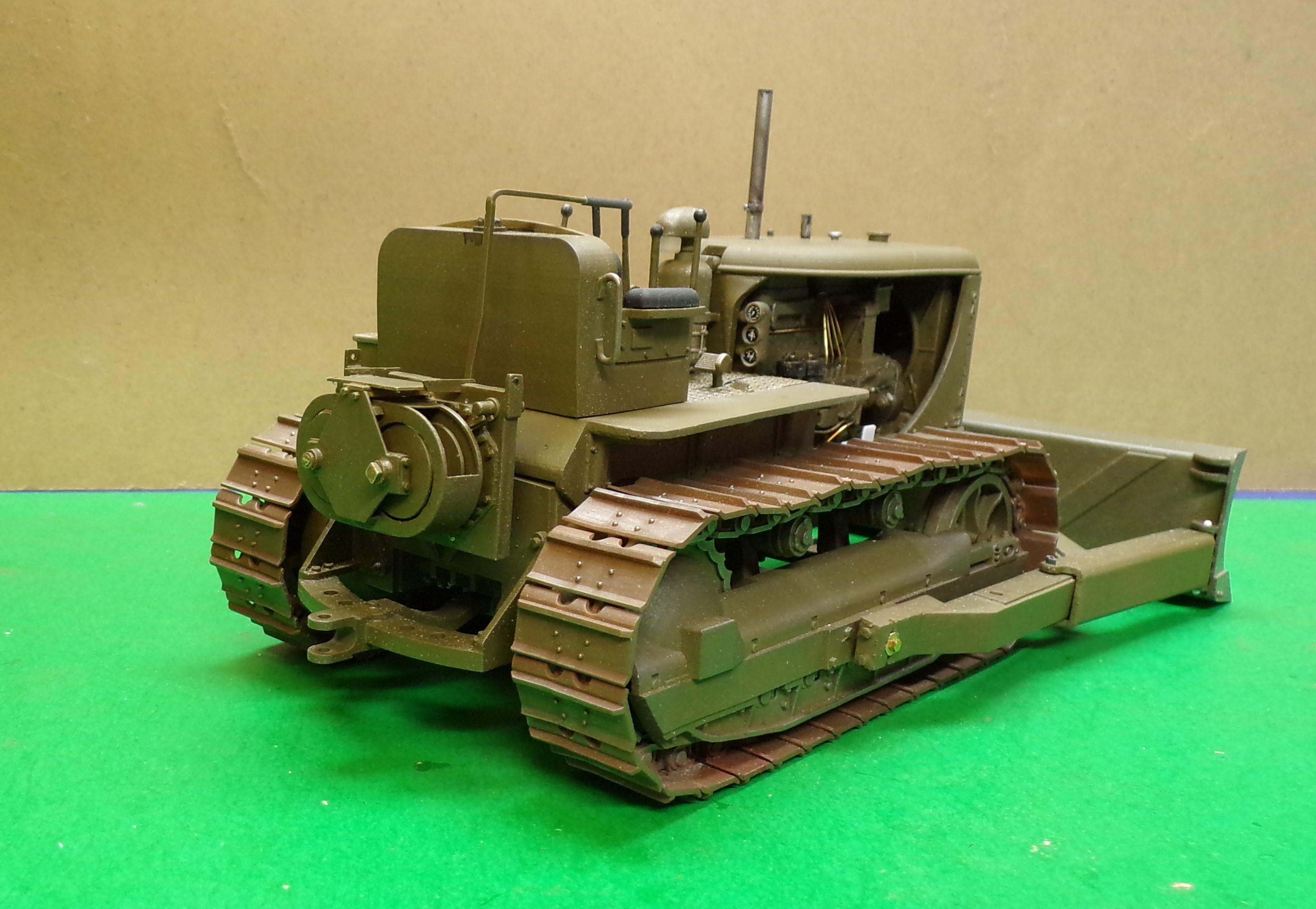
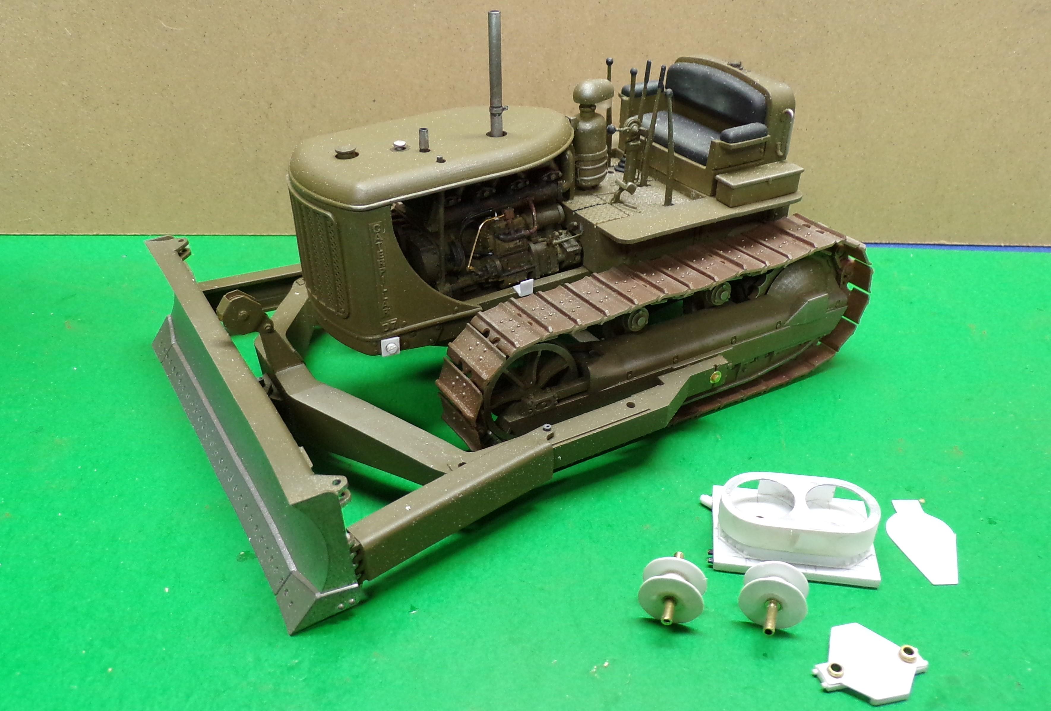
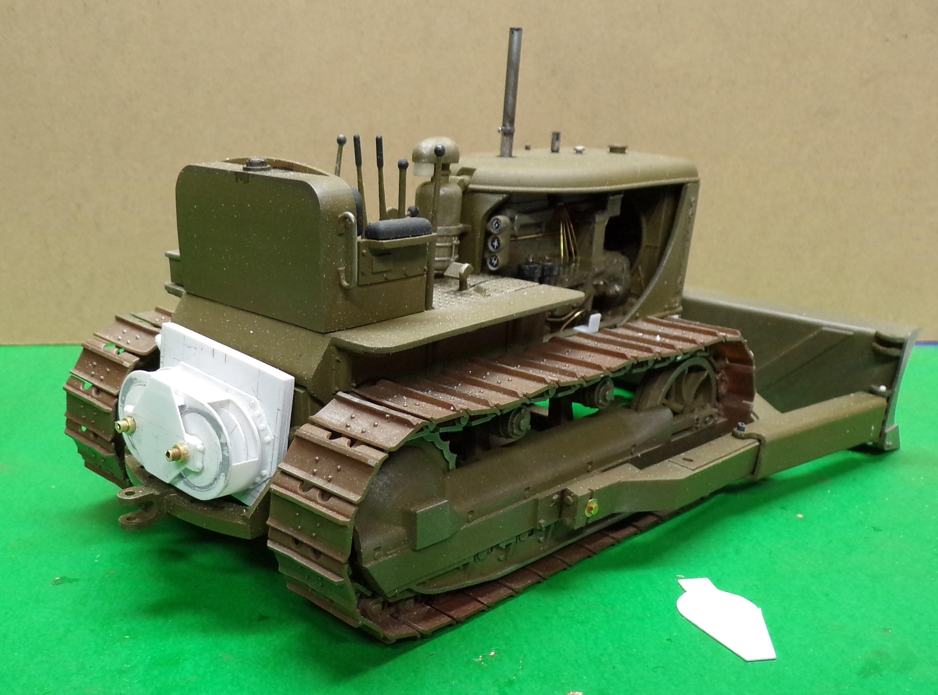
Work continued on the winch for the dozer. Details were added here and there to enhance the look. As part of the build there had to be a way of securing the winch so that the blade could be raised in position once the cables are attached and to stay where put. I hope this works. The drum on the right side is where the cable will be attached. Once the cable frame and pulleys are done it will be strung starting at the drum with a few windings of cable and then will be guided through the rear pulley to the front one and down around the pulleys on the blade. The final attachment is a clamp that is wedge shaped. There are no bolts or clevises that secure the cable. Just the wedge that holds the cable through friction. The harder it is pulled, the tighter it gets. I made the operating lever so that it could put pressure on the center of the drum using a spring on the back. The idea is that when the cable is wound, the friction from the lever will keep the drum from turning. But by pushing on the lever against the spring the drum will be released and the winch can either be wound in or out. I made a tool to fit on the winch center pin so I can turn it by hand. I'll post another picture showing it. Right now there are no pulleys that would allow the dozer to pull a pan scraper. There is evidence that not all D-7's had this feature but it is one that could be added in time. For now the winch is by itself. I'm not sure that the winch is not a bit high. Will have to check the photos of the real ones to make sure. Right now it is just mounted on a pin that can be relocated with another hole.
-
Making Tracks
Chariots of Fire replied to Chariots of Fire's topic in WIP: Model Trucks: Big Rigs and Heavy Equipment
With the M-9 trailer finished work picked up on the D-7. The kit had hydraulic lifters for the blade. I liked the old cable lift so a Letourneau cable control unit had to be scratch built. Here's the beginning of the work. The body of the unit is done along with two cable spools and a plate for the rear. There is a lot left to do to make the two pulleys that are mounted on top. They are not used for the blade but in case the dozer happens to pull a pan scraper, they would come into use. Roughly this is where it sits. Some adjustment of the back of the dozer frame will have to be done to accommodate it. The body of the unit is made of 0.020 and 0.010 sheet stock. 0.030 strip stock and one piece of sheet were used in other parts. Hex rod bolt heads were used in back of the spools.
-
As soon as the dozer is done I will! Promise!