kjohan
-
Posts
191 -
Joined
-
Last visited
Content Type
Profiles
Forums
Events
Gallery
Everything posted by kjohan
-
The -62 NASCAR winner is something I would like to be able to build sometime Would be nice if there would be (another ) reissue of the kit with both NASCAR decals and parts, including wheels", and the Ace Wilson´s Royal Oak Drag racer. Much of the parts should be common Assume difference would be decals, roll bar, stripped interior, exhausts (perhaps) and wheels/tyres When it comes to -62 drag racers yes there was the Beswick Passionate Poncho kit, but that is long gone. Of course it would be another proposition to reissue that one together with some NASCAR bits Dan : may I ask a few questions - what wheels and rims have you used ? The ones in the kit or some aftermarket parts / which ? I bought a set of resin wheels, Partsbox no 1025, which looks fine but according to my understanding they are too small, outer diameter is 27 mm (or just below), my understanding is correct size should be at least 29 mm Correct understanding ? That´s what I could find and what was available here. So any recommendations ? - what have you done concerning the interior (panels, seats, instrument panel )? - the roll cage from where ? As you see I got tempted for another -62, have in the stash already the Moebius -61 Weatherly car (which perhaps would need more realistic wheels/tyres) And huge compliments to your foiling around the windows
-
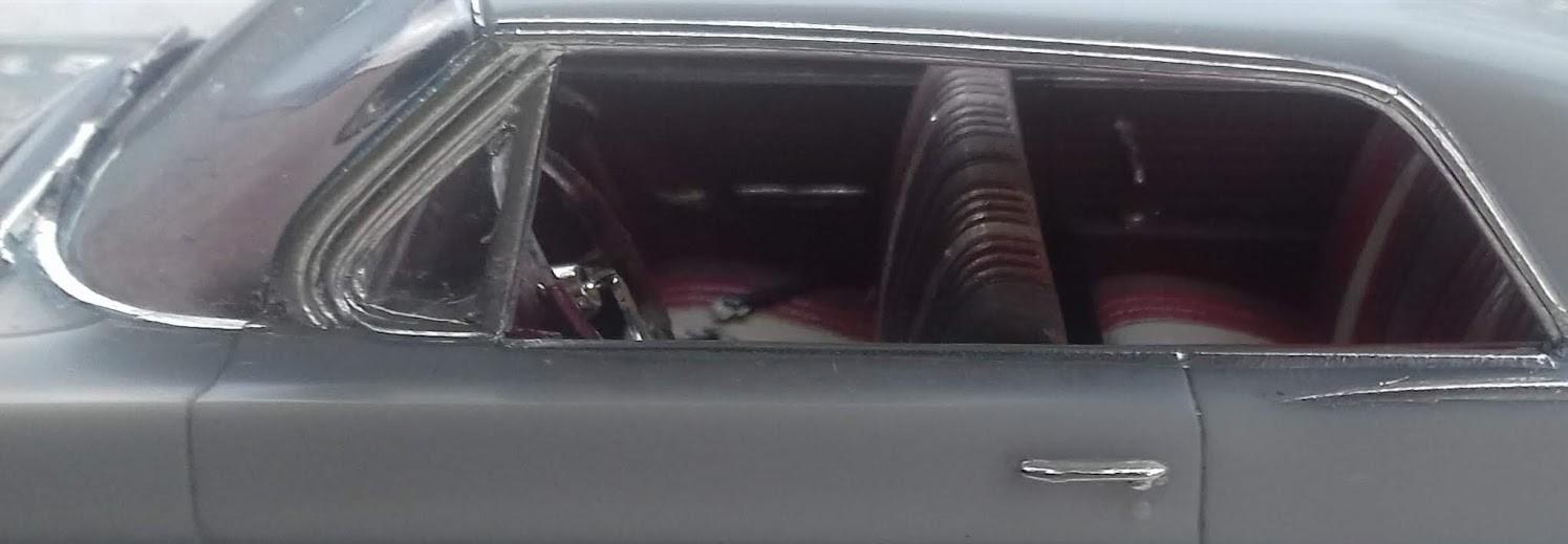
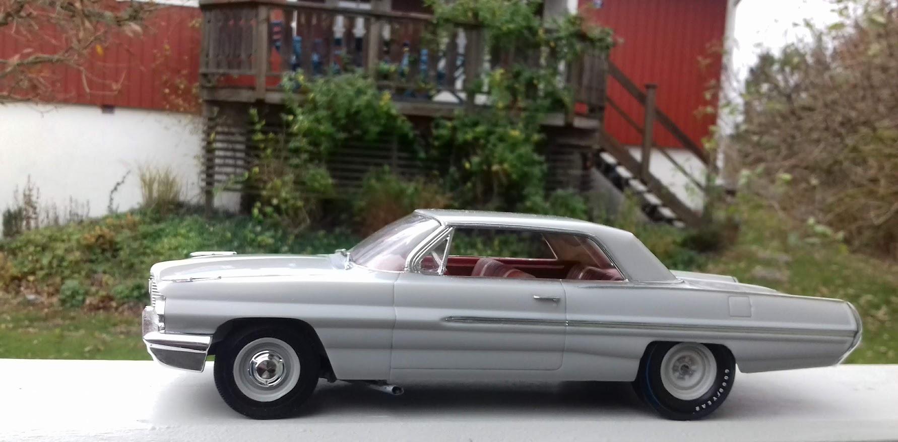
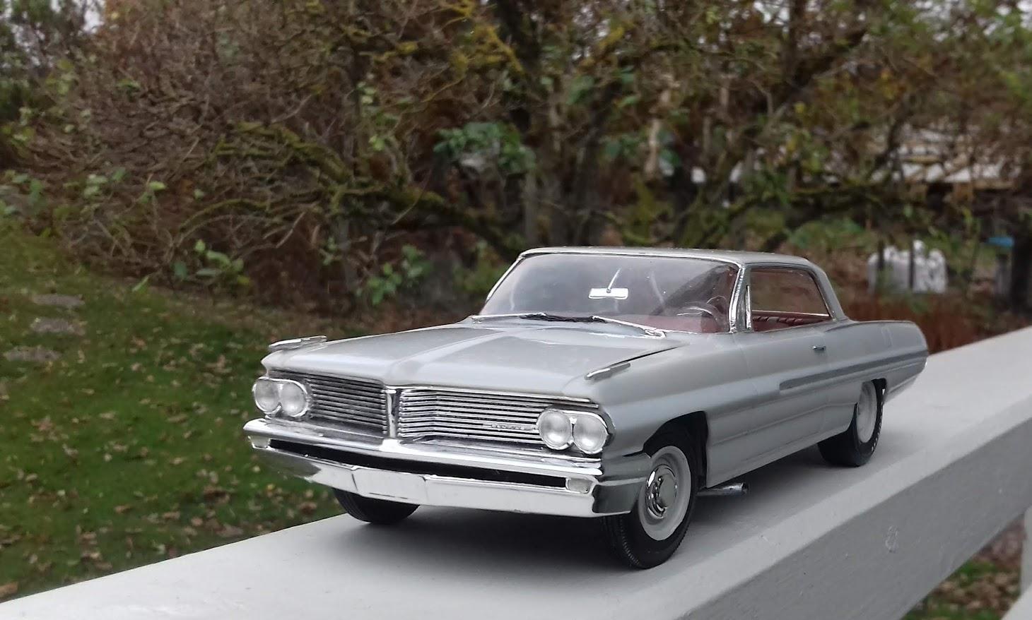
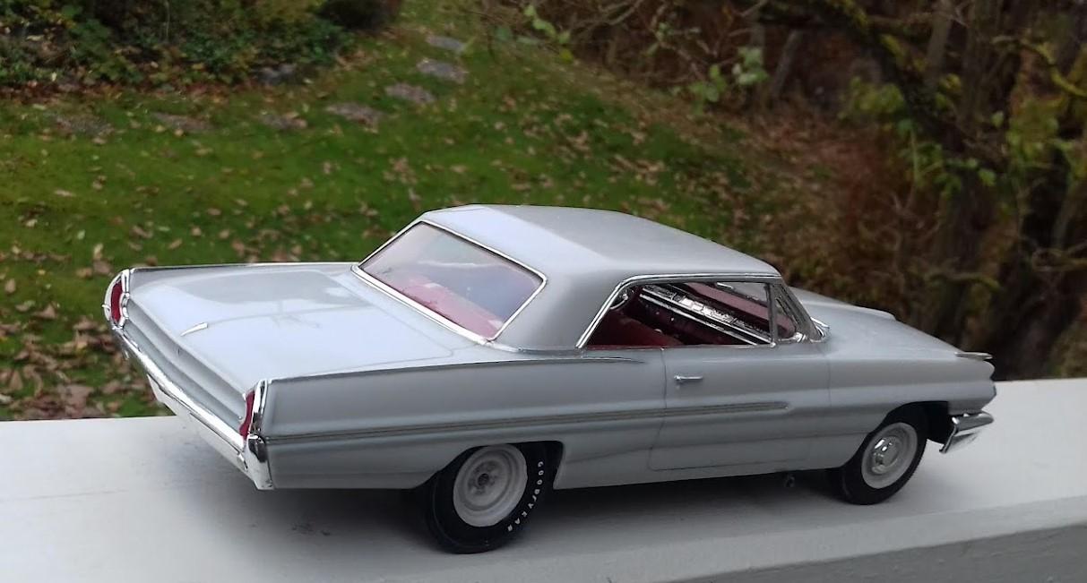
A few days ago I posted my build of a strip-ready Catalina -62 Before that, I actually built another Catalina -62, this one based on the later kit Polyglass/ Gasser. This one is "road-ready". Used the Polyglass tyres included in the kit This one was moulded in white of quite good finish, better gloss than on the grey strip-car. So two layers on white on the inside, to avoid "plastic shine -through" in thin sections, polishing and liquid car wax. Not the best finish in the engine bay Also foiling could be better. But i must say that the lower corners in the windscreen/vent window area on the GM cars from these years, are not easy. For some reason I erronously thought there should be a long chrome strip in the centre of the trunk lid, thus foiled and cut it with some effort. When i found out it should not be there, there was no way I would take it away, given the invested work. The exterior rear view mirror on the left side is from the Strickler Chevrolet -62. Thought it would be morre needed on this one. Attach a couple of photos of the pair also Comments and feed back wellcome / Gunnar

-
Thank you all for your kind words @TransAm Mike : see my (lenghty) comments higher up in the thread about problems encountered. Before building this one I built another one, based on the later Polyglass/Gasser kit. (will post a new thread on that one shortly). Same issue there with the "thick hats on the wheel bushings" and the positioning of the side panels in the front end / under the front glass etc. Would advise to sand away / chamfer the lowest parts of the windshield / side vent glasses as much as possible once glued in place or after a dry fit, this to avoid the potential interference but of course also not to create visible gaps along the undersides of these glasses. A little chamfer on the top of the sidepanels just under the vent windows could also be helpful. On the first build, that was necessary to get the body down into its proper position. There are location tabs in the front , but they are far to weak compared to the sturdiness of an interference between the sidepanels and the underside of the side vent windows. This is not to discourage, just sharing experiences, if possible making it easier
-
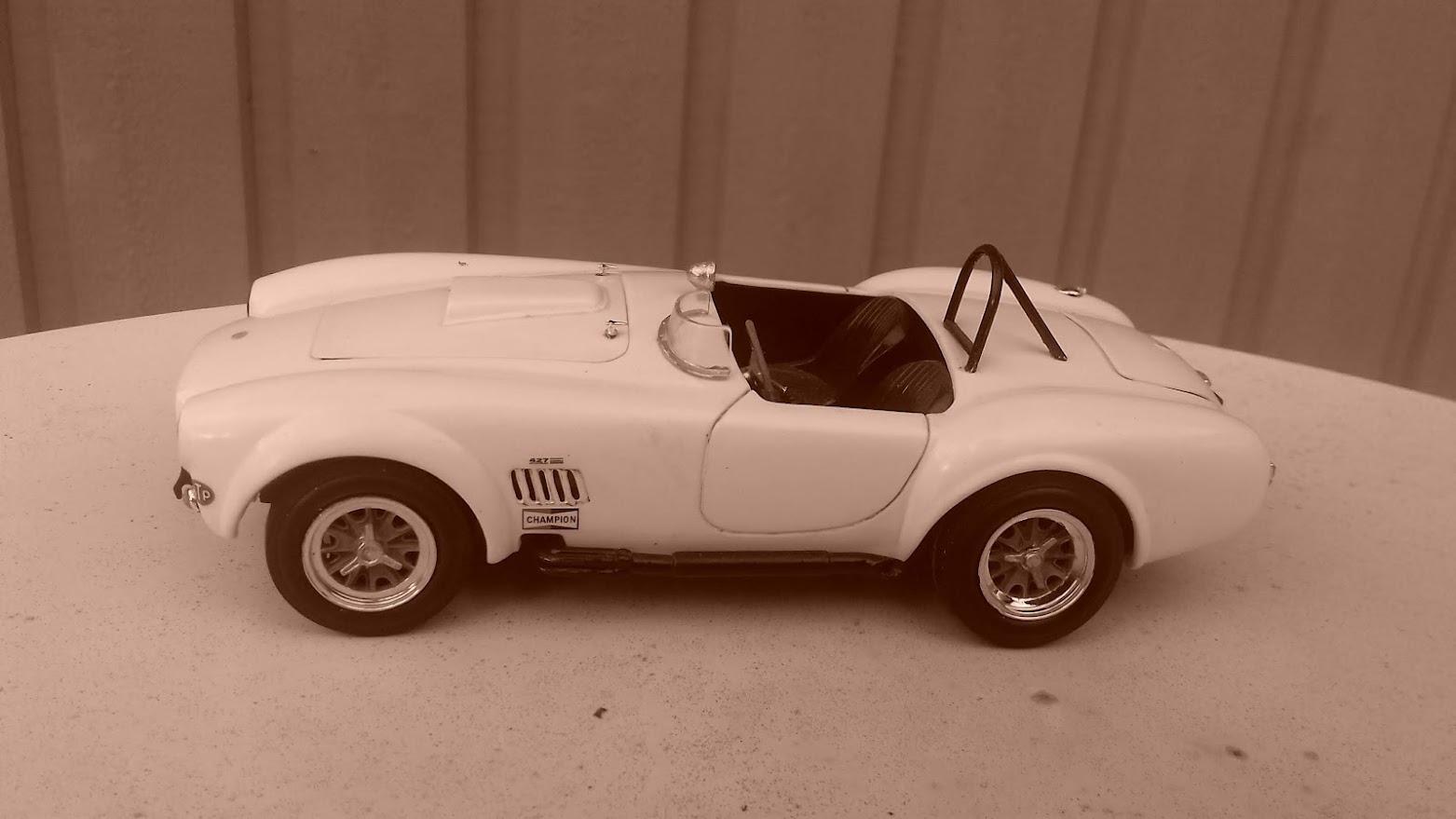
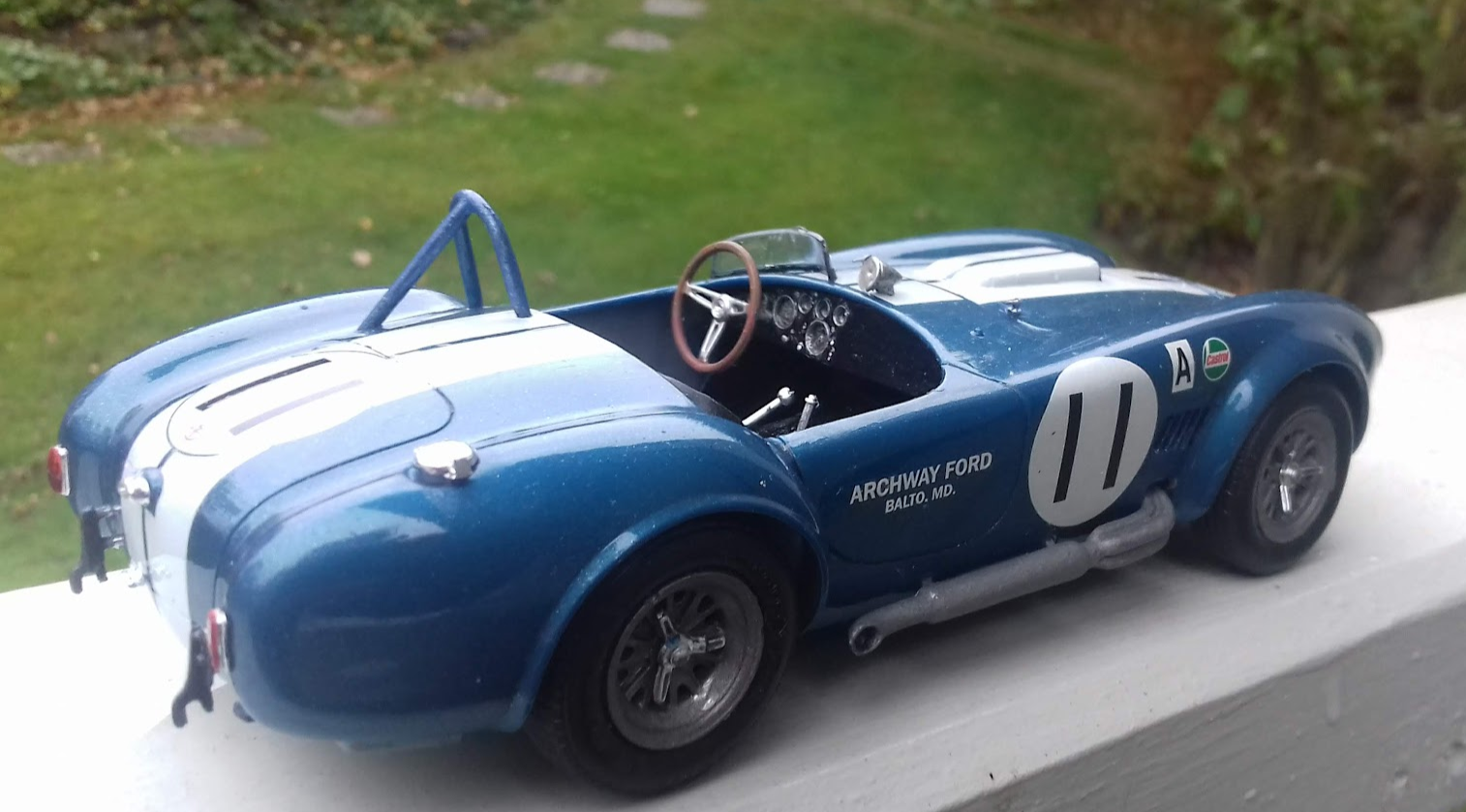
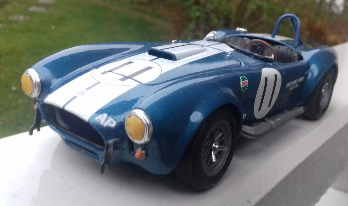
Soft autumn light today, slightly cloudy, sun a bit bleek Thought it would be nice to just take a couple of photos of a Fujimi Cobra 427 I built 3 years ago. Took one photo (the last one here), Battery in the phone went low = swithched automatically to black-white. When I noticed first thought: " This was it for today" But looking at the first two I thought "Perhaps not so bad after all", took a couple of more photos, and then it WAS the end of the battery. For some reason they got an almost Sepia tone, quite appropriate for the day, and in my eyes giving an almost "period atmosphere". So I take the liberty to post them here, also the colour photo as a reference (there came a not so good yellowish shade/ reflex on the door) Having recently built the Revellogram 427, the differences in body shape has become rather evident for me now. The Fujimi is in lack of better words (sorry for my English)stubbier vs the Revellogram lower and more fluid form Understood that the Fujimi was modelled after a continuation car. Is there any knowledge of the chassis number of this one ? As well ; is the chassis number for the original for the Revellogram car known ?
-
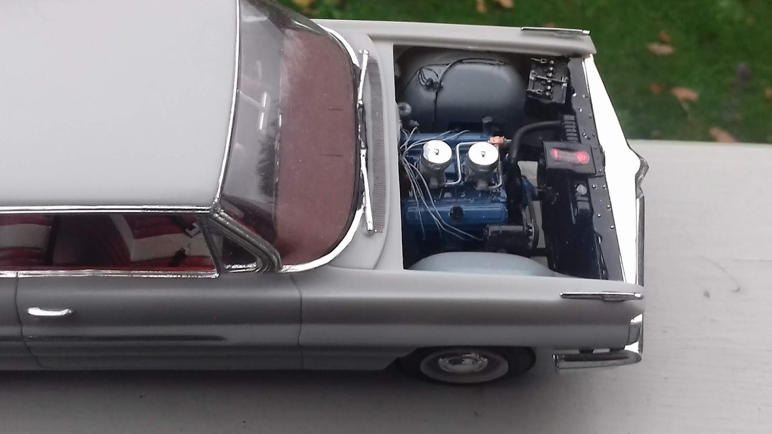
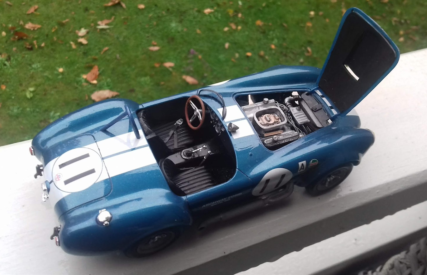
The fuel lines were actually included in the kit It is a OOB build with the addition of only the ignition cables, additional exhaust pipes, BMF inside and outside In general a good kit Only two items at least for me 1) The wheels are attached to the axles with bushings recessed in the inner parts of the rims. The "hat of the bushing" was a bit thick = in contact/ interferred with the insides of the outer halves of the rims. Preventing good rim-to- tyre fit and obstructing rotation. Thus these "hats" had to be ground to reduce the thickness AMT/ Round 2 would need to look at the dimensioning or the production tolerances here 2) The inside of the firewall should have two parallell small vertical ribs on each side, these to locate the front ends of the respective interior panels in a positive way. The interior panels are located at the rear wheel housings and along the floor, but it is very easy to get a minor dislocation in the upper corners of the front ends of the panels. That is very sensitive from two aspects - to have proper fit between the body and the panels along the upper contour no large gaps "sideways" - IF one of the panels (or both) is slightly "scewed outwards", it (they) will interfere with either the body or the underside of the windscreen/ vent window glass Both interferences will prevent to body unit to come down properly on the underbody/chassis/interior unit In turn leading to the nose of the car being too high. Quite difficult to remedy as everything in the respective units are glued together at that stage. To introduce two pairs of location ribs on the fire wall would be a very easy tooling change before a next production run (if any), the tool most likely being apart in the preparational stages anyway, and it means just removing a little (very little) material in the tool. Why two ribs / a pair on each side ? That way I would assume most builders would understand the purpose and how to build just by looking at the parts, e.g. no need to change and reprint the instruction sheet = cost avoidance Otherwise a fine kit from my perspective
-
Thank you all for kind words on my simple build Concerning the exterior colour: have found that in the cases when I use the "plastic unpainted", either with wax or clear coat, it is useful to have painted the inside a couple of times with a colour similar to the exterior, or light/ medium grey This to provide "shine through" in thin sections or when light can come in "from behind" Concering the interior Below is attached a picture take now, really nothing which should be posted. But anyway, that is what I could get from a quick photoing with the phone of the finished car, tried with additional light but that just became very harsh. It is supposed to depict the Pontiac three colour scheme The darkest part is Humbrol flat rust red no 73,perhaps it should have been mixed with a little more red the medium red is the Humbrol satin red 174 and the light part is the Humbrol flat white, with just a little light grey in it, otherwise too bright (actually thereby also matching the exterior quite well, though not very obvious in the photos) Satin clear over everything afterwards There is a lot of chrome on the interior, both on the IP and the door panels I applied BMF, fairly "large" areas and then brush painted with the desired colour over what should NOT be chrome. The chromed mouldings etc are more or less alwas raised, that is you can paint with the support against a "raised wall", helps to get an even line. and on top of the "ridges" it is possible to clean afterwards with i.e. a tooth pick if needed. i.e. more or less the same method as described by i.e. Steve G for exterior badges In narrow areas like in the instruments, the dark paint applied is very diluted (thinner, white spirit) to flow down and lay only at "the bottom". Tamiya black panel line colour also useful. Have tried to apply BMF only "locally", but it is very difficult to have it stay in place on the small parts like i.e. the window cranks or the interior door handles. The belts I cut from thin "electrical insulation tape" The buckles I cut from a 0.25 mm styrene sheet The "female" buckle I make from gluing together three layers (sometimes only two) to get the additional thickness of this buckle. The centre "layer" made somewhat larger to accomodate the space required for the "loop"/"hole" for attaching the belt to the buckle. At least one additional smaller layer facing uppwards,being visible, or one layer on each side of the centre piece So it is all very crude
-
A quick build during the summer, based on the aMT 421 SD kit, the one with the dark blue car on the box Just polished the body and car wax thereafter The stock exhaust as well as the straight pipes are in place, re Y-connection on the ends of the headers The engine should have had a slightly more greenish hue
-
Concerning location of batteries (again) Earlier in the thread I learned that the (dual) batteries were located behind the passenger seat in the 427 (Mk3) racers What about the early M1/Mk2 racers , like the ones driven by Miles, McDonald in 1963/-64? Where did they have the battery/ And how many ?
-
Another thing which makes me confused: Oil pans on the engines in the various Revell kits Have built or in the stash: - the "blue kit", where the kit is supposed to depict the CSX3002 (though the body nose area is incorrect), this actual car having a dry-sump lubrication but in the kit there is no filler on the right fender, nor an oil tank inside the fender - the King Cobra / Baldwin - Motion drag racer - The Feinstein CSX 3009 (ex Essex Wire) alt the Keck CX3008 (both cars more or less possible with the content of that kit) Pictures of the actual King Cobra / Feinstein / Keck cars certainly shows no filler on the right fender, said to be the visible sign of a dry sump car, those being very few So presumably they are "wet sump cars" All three kits have the same , a rather thin "shallow", more or less flat oil pan Which perhaps could be dry sump pan , in that case relevant for the first one, CSX 3002 (though still incorrect for the reason above) The sumps for the cars with wet sump systems i assume should have had a deeper hump/tray ? Have built the Fujimi Essex wire car CSX 3009 and that kit have a deeper hump) So my confusion is: What kind of sump is it, which is used commonly in all these Revell kits, depicting cars with most likely different oil system ? And therefore perhaps should have had different execution of the sumps ? What is the correct sump for the CSX3008 and 3009/ how does it look ? Have been through many net sites , no conclusion possible for me
-
Re comments above: Built a few of the Heller kits 40 years ago; Brabham (F3 I think) , Porsche 907 (or 908?), Ferrari P4 & 512, Porsche 917 Gulf/ Wyer, have the -71 Martini in the stash. They were quite nice and assume at least the Ferraris would catch interest in the wake of the Ford vs Ferrai film (perhaps dwindling now) The Porsche 907/8 was a bit short on parts/ details but looked quite fine The Brabham was so petite and spidery in the suspension, but very nice looking Now to my own little wish: The 1964 Mercury Marauder With proper Nascar wheels/tyres, barren interior and instrument panel, decals for the Bill Stroppe cars (Panelli J, Darel D, Dave McD et al) And proper routing of the exhausts coming out in the sides/above the sills/ behind the B-post. (No moulded in exhausts all the way back to the rear) Probably something could be added around the tank/fuel filling system That is: a kit similar to what Moebius did with Weatherlys -61 Pontiac (plus little more) Those old Nascar racers have in my eyes a very distinct allure and should deserve kits that "go one step further" Venture a guess that those interested in these cars could perhaps be willing to spend a few bucks extra to get the real thing
-
My attempt on a Cobra
kjohan replied to kjohan's topic in Other Racing: Road Racing, Salt Flat Racers
Thank you all for your help with information and kind words on the outcome of this one Gunnar -
Re Rick´s very instructive photos My understanding from them is that the foot boxes had the naked FRP coulor "all around" on the outside in ther engine bay,' when the cars were delievered to the customer (unless the owner choose to paint them I assume) Also the "naked" FRP under the car up to the joint with the steel floor ? On the inside, judging from the top photo, it seems like black or dark grey colour was applied, which has been worn/ the FRP colour coming through under the pedals Correct understanding ? / Gunnar
-
What paints/techniques do I need to get this look?
kjohan replied to Monty's topic in Model Building Questions and Answers
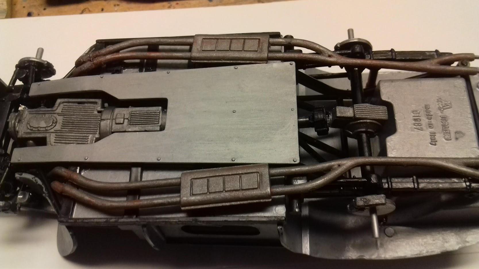
This is the underbody of ongoing build of Italeri Ferrari 259 GTO Concerning the exhaust: The plastic was moulded in medium grey. I brushed firt Humbrol Matt Rust no 113, not fully even coverage, some variation Thereafter a couple of unsystematic rounds with Gunmetal grey gloss metallic. no 53 When the paint started to dry gave it some "stabs" here and there with the brush Hope it works with rhe photo this time
-
Thank you all for your encouragement and help with information / Gunnar
-
My attempt on a Cobra
kjohan replied to kjohan's topic in Other Racing: Road Racing, Salt Flat Racers
Thanks for nice comments, really appreciate Gary´s comment on having seen the actual car racing in period. A couple of comments - The kit came moulded in blue "metallic" of faily good finish There were a couple of weld lines in the material, where the material came flowing from different directions Furtunately those were in the areas covered by the decals So I took the easy way out, polished the plastic and just applied one layer of clear coat, a little polishing again thereafter - The external oil filler /filter to the front left of the engine was moulded together with the upper coolant hose. Cut it loose and attached it instead separately to the front end of the engine block, a bit too low but did not want to have conflict with the closing of the hood. By having this as a separate unit I could make oil hoses both to the oil cooler in the low front as well as those connecting to the engine block, just below in the lower left corner just above the joint between the block and the oil pan. Not possible to show in photo, no one will see it But I know it´s there, that´s sufficient - would have liked to have a dual battery installed behind the passenger seat but i learned about this after having glued the seat in place, And apparently did a good job with this gluing, impossible to pry loose So ... But onn the next one(s)... - In general a very nice kit to build They must have liked what they did when the constructed and formed the kit The only strange thing was the steering rack, which, judging from the angles of the rods and the position of the steering gear on the rack, seemed to belong to a RHD car. The attachment of the rack to the front wheel uprights was also weak and fiddly. Otherwise Ok Now in the finalizing stages of an Italeri 250 GTO, if you built a Cobra, you need to keep the balance with a Ferrari. Thereafter finishing a Ford 1930 coupé, and then back to Cobra(s) ; the Ollie ( probably this also in the Feinstein execution) and the Baldwin Motion drag racer Amazing how gluing pieces of styrene can keep you busy -
My attempt on a Cobra
kjohan replied to kjohan's topic in Other Racing: Road Racing, Salt Flat Racers
Strange with the photos I see them on my opening opening of the thread Try another method Try again
-
Here is the result of my attempts to at least approximate the CSX3008 Based on the Revell/ Monogram kit, the version moulded in blue. Got some very appreciated advices in a another thread, thanks very much There remains much to learn on build and photos but still great fun. Gunnar
-
Have finalized the first one, the "blue one". Will soon post a couple of simple photos of it, very humble But I have a couple of more to build and the more you look, the more questions you get. Having no real life hardware to look at, I look for the possibility for help from the knowledge in here. 1) Concerning dual batteries on the racing 427s What was the voltage on the electrical system ? 6v or 12 V ? Suppose the batteries, regardless of the voltage, were coupled in parallell ? (otherwise / if in series the voltage would double) 2) Have seen mentioned that the foot wells were made from glassfibre -reinforced plastic / GRP, and that was an AC design Found on the net a photo of one of the very first ones, perhaps the CSX2000, under build. Rolling chassis with the foot wells, including the upper part, installed Certainly looks like the entire "boxes could have been in GRP. Photos in the net shows the foot wells / the visible upper part of the foot wells on the old cars to have a a colour and a sheen similar to GRP ( unless painted) But what about the 427s/ the Mk3s , being considerably re-engineered, compared to the Mk1 and Mk2 cars ? Were the foot-wells also in these generations in GRP ? Or was the material changed to metal, alu or steel ? Have looked in many photos on the net, no clear clues. Cars from more recent builds seems sometimes to have metal, judging from the photos ? but how about the early ones , the CSX 3000-series / the SCs ? Appreciate very much if someone could help to clarify / Gunnar
-
1) Now that the 65 Pontiac Bonneville is coming again it would be very nice if primaily the 1960 and -63 would come out. With proper decals and wheels / tyres for both drag racing and NASCAR. Apparently it can be ok cost/businesswise to include double sets of wheels/tyres, judging from the -62 Polyglas kit, I assume, if proper vinyl NASCAR wheels/tyres from that period were tooled, they could be used in other kits also, to distribute the tooling cost These two model years would make it possible to build the entire, quite remarkable, performance development for Pontiac, really starting with the -60, via the variuos Moebius -61s and AMT -62s, over the various GTOs and Firebird/Trans Ams. The introduction of the fast backs in MY-65, certainly gives the -65 Bonneville its deserved place in that chain but after that the full size cars at least in my eyes became less interesting Of course also the nice -64 would be a wellcome addition 2) A good Cobra Coupé Gunze ?
-
Now I have got myself an Essex Wire kit as well as a few batteries, so .... But I shall first finish my "approximation" of the the Keck car, very little remaining. Thereafter finalizing an A-Ford Coupé, fairly far in progress, but interrupted by the Cobra, perhaps one should say "the Cobra poison" Then back to the snakes again. Thanks for feed back so far.
-
Yes, need to find one of those kits Meanwhile I finish "the blue kit" with CSX 3008, Harold Keck , no 11, livery. And , after a lot of searching, I finally found on the site barcboys a photo of Hal in his car, at 1965 Vineland. With what apparently must be a 3-point belt, a single shoulder strap clearly visible, hanging over his right shoulder and chest, and attached to the centre of the car/ "under the rollbar´s right leg" So I´ll try to make something homemade of that kind. In the same site there are photos of Hal racing Skip Scott in CSX3009 "Ollie..." as well as Skip/ "Ollie" alone. No belts visible on that car. But of course the possibility for lap belts. Passenger seat already firmly glued into its place = unfortunately no possibility to get a long battery in there as described by JC . Sorry JC But on the next build .....
-
Thanks JC for a very instructive scheme Have come a bit further, building the Revell kit molded in blue. And found that the rear tyres have very clear Good Year lettering but the front tyres seem to have Firestone ( the letters are small / need to look with a magnifying glass so the question comes: did they really race with different tyre manufacurers front vs rear ? (Photos I have found , shows no such mix, and Good Year seems to be the dominat brand) Or is this a mix by the kit manufacturer
-
Thanks for information and fine photos JC´s decal sheet perhaps can be interpreted as a road map to many interesting hours at the work bench, perhaps also a few moments of frustration, decals being what they are I had mine a few hours ago, when I applied the broad white stripes at the Cobra hood scoop. Did a small45 degree cut at each of the rear corners of the scoop , but could not avoid a couple of small wrinkles. Used a Tamiya decal glue, fairly new I think, improved situation but not entirely good. How do you experienced Cobra builders tackle this problem ? Concerning the (dual) batteries at the rear/ behind the seat: The cables starting / ending somewhere in the engine bay / where ? Perhaps in one of the small boxes moulded on the fire wall / If so which/where ? Or somewhere else ? JC: where have you found this type of narrow / long batteries ? (no batteries whatsoever in the kit) A similar question concerning the horizontal pipe (on the right side of the carburettor/ bathtub), which feeds fuel to the (single) carburettor via two short hoses. At the front end of the pipe, there is another , thinner hose going forward, "rounding the front end of the carb / bath tub" and thereafter disappearing, may be downwards in an array of other hoses/ pipes/ ignition cables and what not. So where is it actually routed ? Surprising how many questions some injection moulded styrene can arise, but it is very stimulating to learn Regards / Gunnar
-
Thanks Gary for your kind offer You have a PM
-
Thanks JC for clarification and very instructive photos of your fine build. As I understand it from your comment, that neither the 3008 nor the 3009 have the dry sump system you refer to, no filler cap visible on the right fender But the 3002 has the cap and tank below, which is clearly demonstrated on a Lou Constable YT clip, as well as can be seen on photos. Onbviously you have found that the 3016 had seat belt of the lap belt variety. Found auction pictures of another old warrior, the 3006. No belts. So it is a bit confusing what was the practice.