François
-
Posts
497 -
Joined
-
Last visited
Content Type
Profiles
Forums
Events
Gallery
Everything posted by François
-
That was one of my original plan but didn't like it at first because i thought it might give a fake look to the engine but I really like your idea of painting certain portion of the bloc and head. I could leave just a slice unpainted. A slice wide enough to show a complete rod/ piston/ valve assembly, I'll try to model it and see what slice would be best left translucide. My concern with this idea is that clear resin is not really clear after curing, it becomes hazy. I'll have to test it to see how well moving parts show thru the haze. Thanks Messer !
-
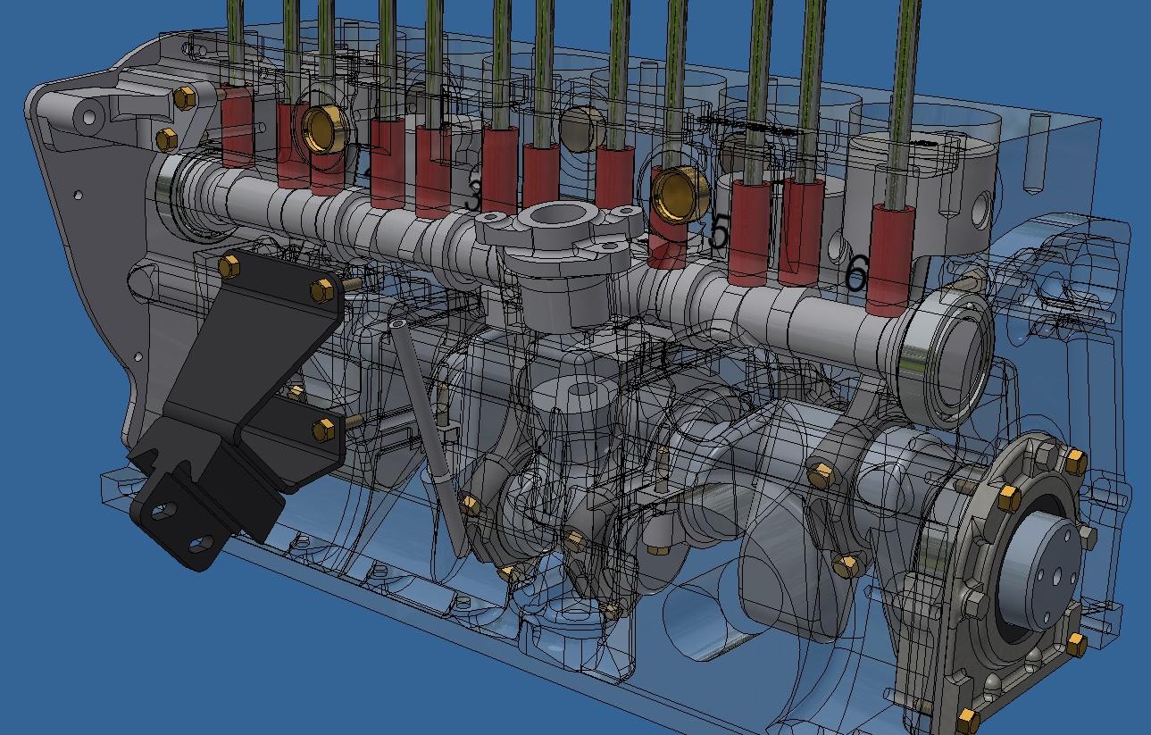
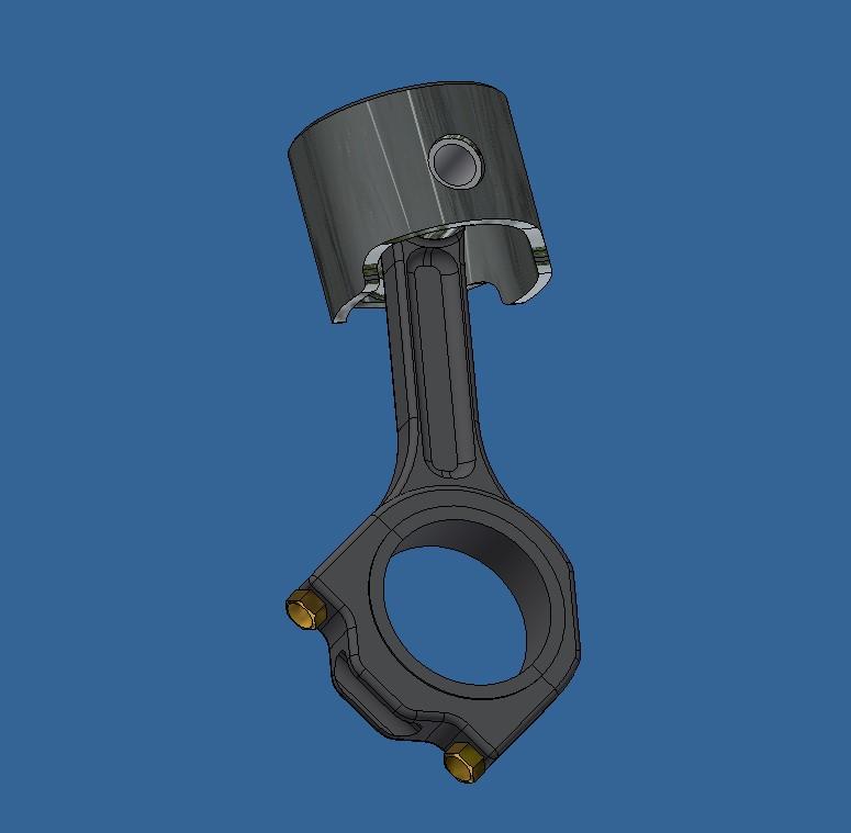
I'm almost done with the engine. I still need to do the intake manifold and the carburators, I'm keeping the carbs for last since they are quite complicated. The Stromberg carburators were one of the things a TR6 was known for so I want to get them as right as I can. Once all of this is done, I have to figure out how to showcase all these moving parts. The rocker cover and oil pan will be removable, that's a given. But i'd like to dive in deeper and look at the valves, pistons and conrods as they move. I might make a few cut-outs here and there, not to sure just how yet.

-
Thank you bainford, yep those are the numbers of the bloc and head. There's a good chance that they are not the original numbers, I never took the time to check back when I restored the car.
-
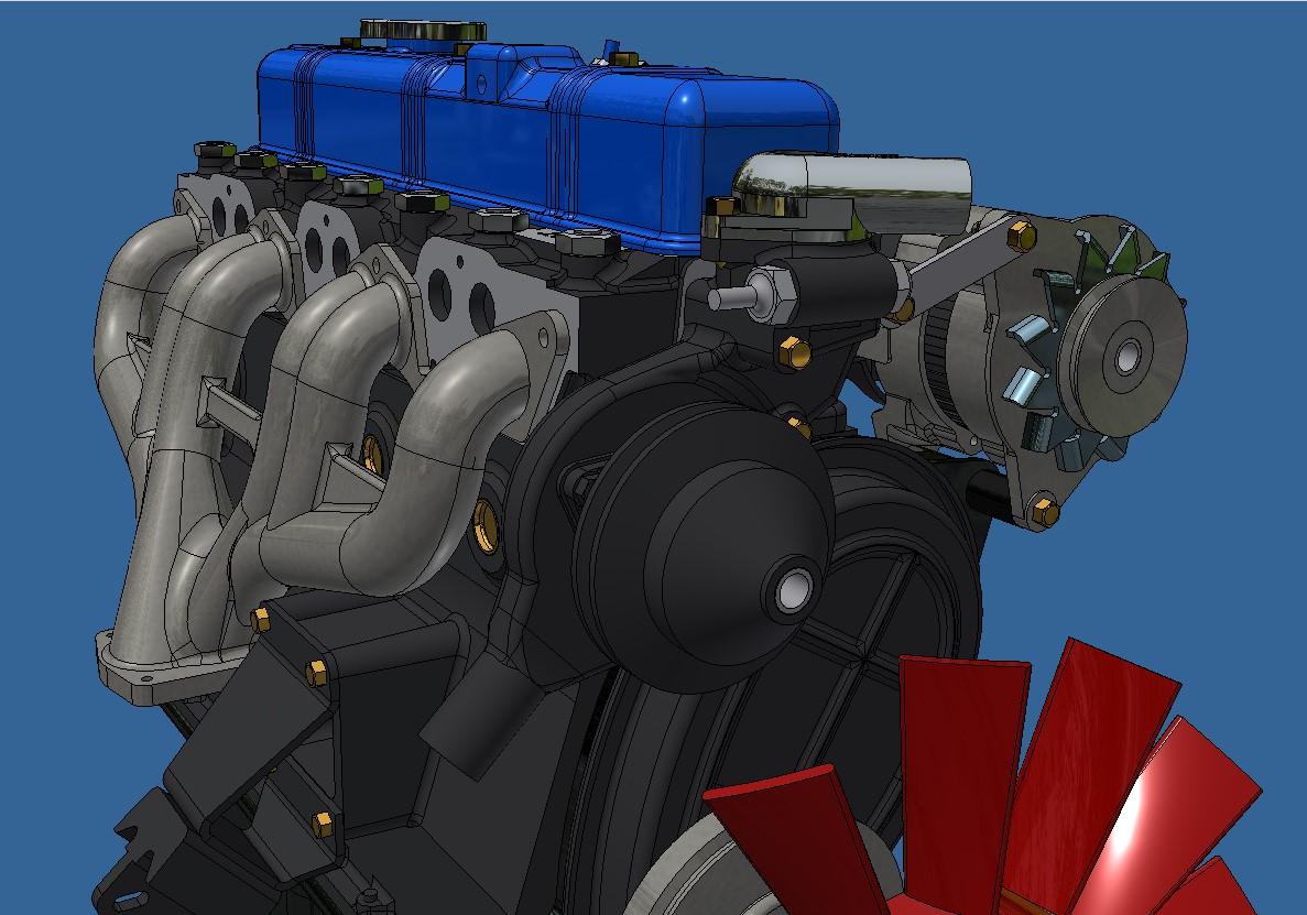
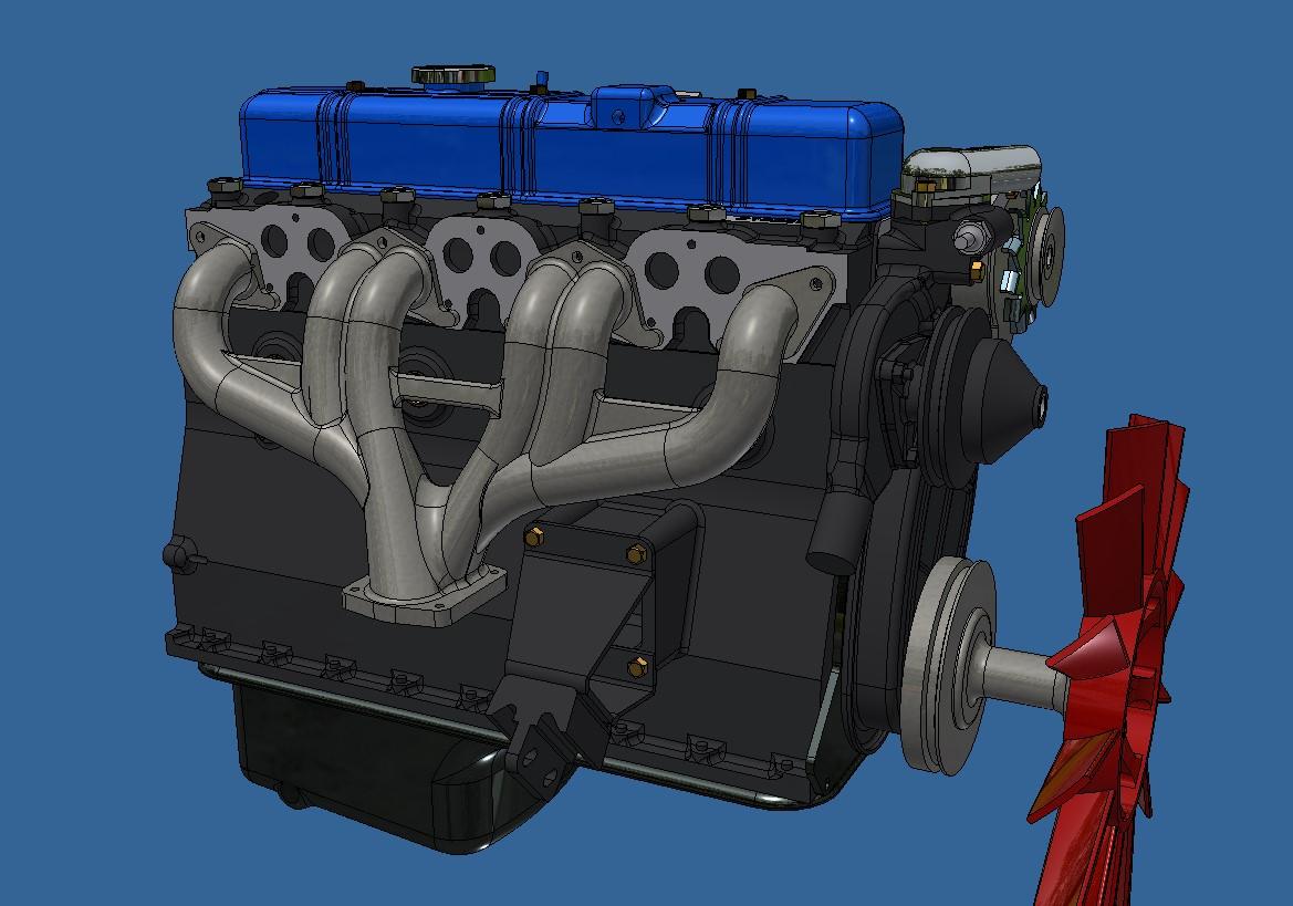
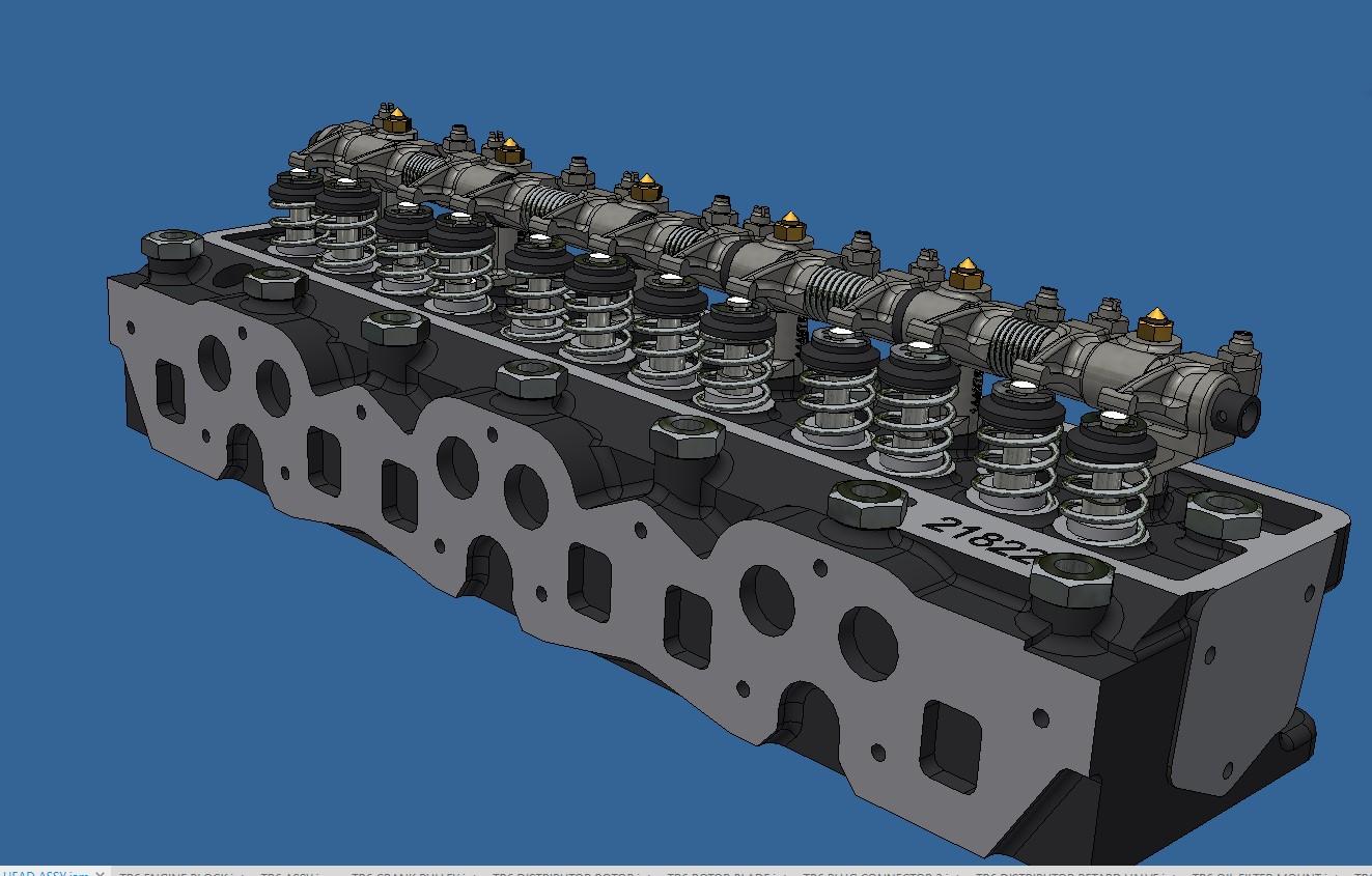
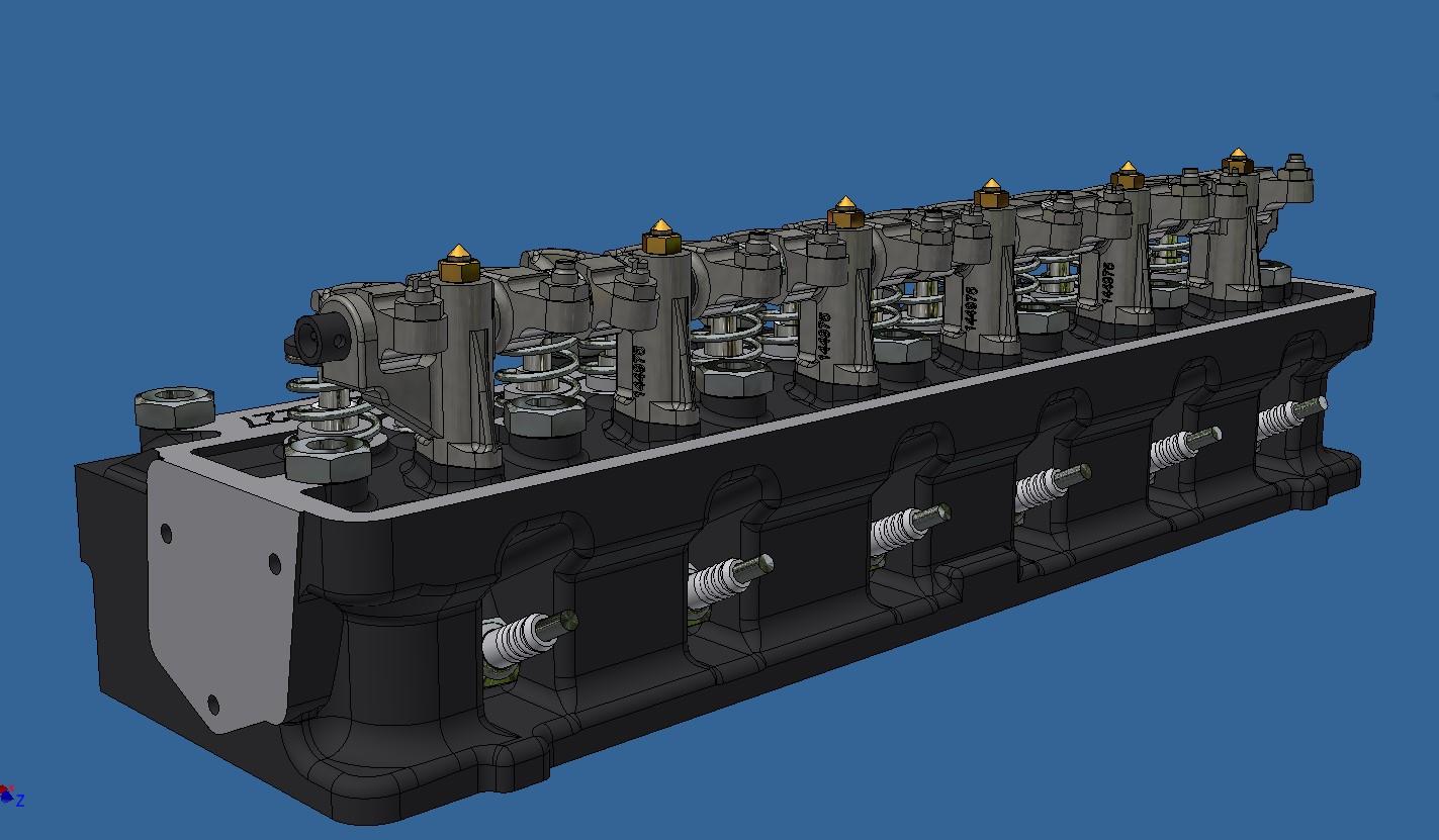
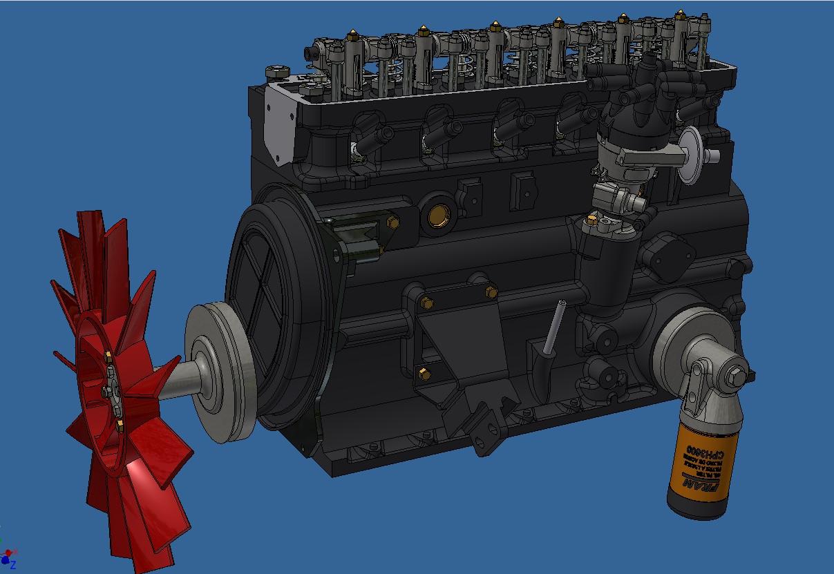
A bit more 3d modeling done. The engine head is complete, the distributer, the fan and the oil filter. There is still a lot do on the engine, there's the water pump, fuel pump, alternator, coil and bracket, intake and exhaust manifold, carburators, rocker cover and many little fittings and connectors. I might start printing in the next few weeks.
-
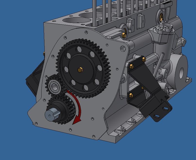
Today, I modeled a few more parts. The motor mounting brackets, the alternator mounting bracket and the distributer mounting bracket. I also completed the freeze plugs. But the main thing I modeled is the camshaft. I'm pretty sure I got the timing of the cam lobes right but I'll double check. It's very amazing what you can get from Google AI! A few good questions and I had all the info I needed. 110 deg between intake and exhaust cam lobes, a .24 inch lifter rise (.04 inch at scale) and 120 deg between each pair of lobes and in what order to position them which is basically the firing order. Once the camshaft was done, it was a breeze to but in the lifters and pushrods. On the real TR6, the camshaft is driven via a timing chain at a ration of 2:1; 2 rotations of the crankshaft for 1 rotation of the camshaft. After a simple calculation (360deg of camshaft rotation/6 cylinder x 2) you get 120deg between each pair of cam lobes. So didn't really need Google for that one. Now, finding a fonctional timing chain at 1/6 scale is kinda hard to do so instead of a chain, I'll be using spur gears. A 24 tooth on the crankshaft, a 48 tooth on the camshaft plus an idler gear linking the 2 to have the both shafts rotating in the same direction. I then finished of the day by modeling the camshaft drive cover. You would think that with all this, I would't have time for anything else but I went paint shopping, took a long walk and made a killer pasta sauce. All in a days work!! Freeze plugs and brackets More freeze plugs Camshaft drive Camshaft (red) with lifters and pushrods Video showing moving lifters 20251129_194024.mp4 If you're like me, you are anxious of seeing some printing/painting/assembling but unfortunately, I still have a lot of ed modeling to do first.
-
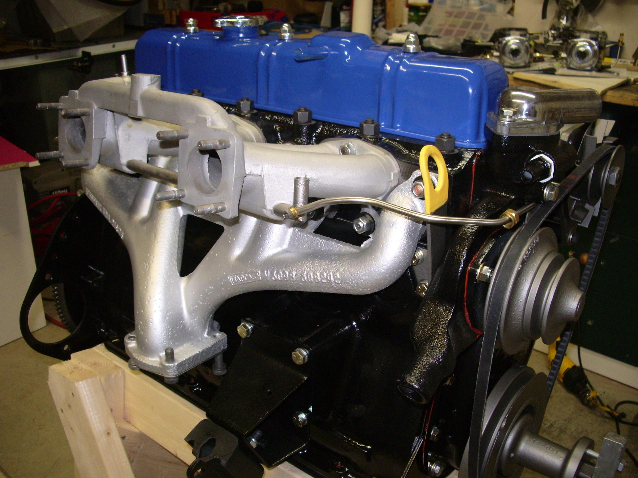
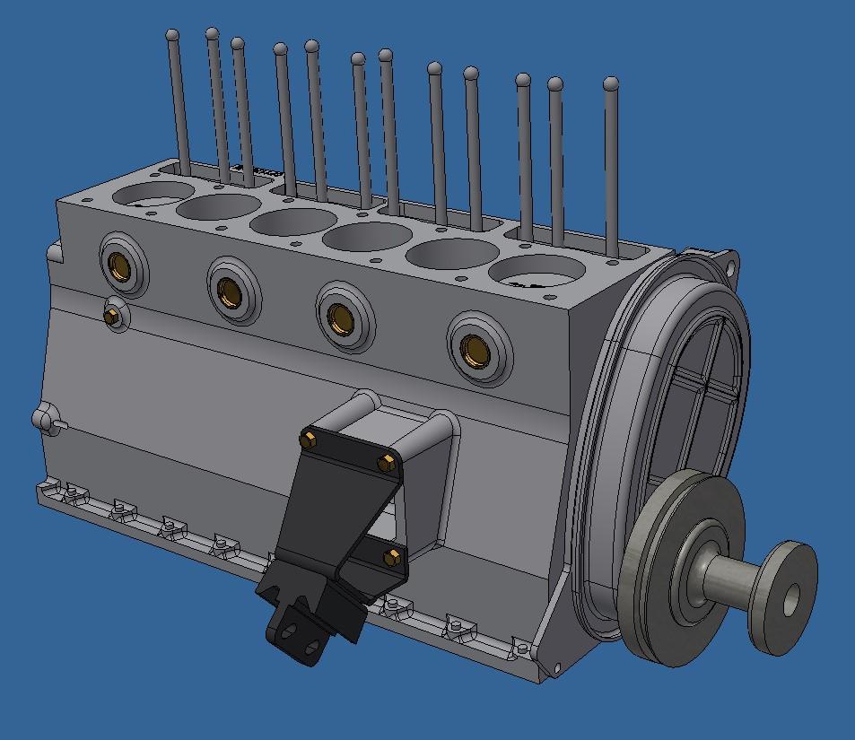
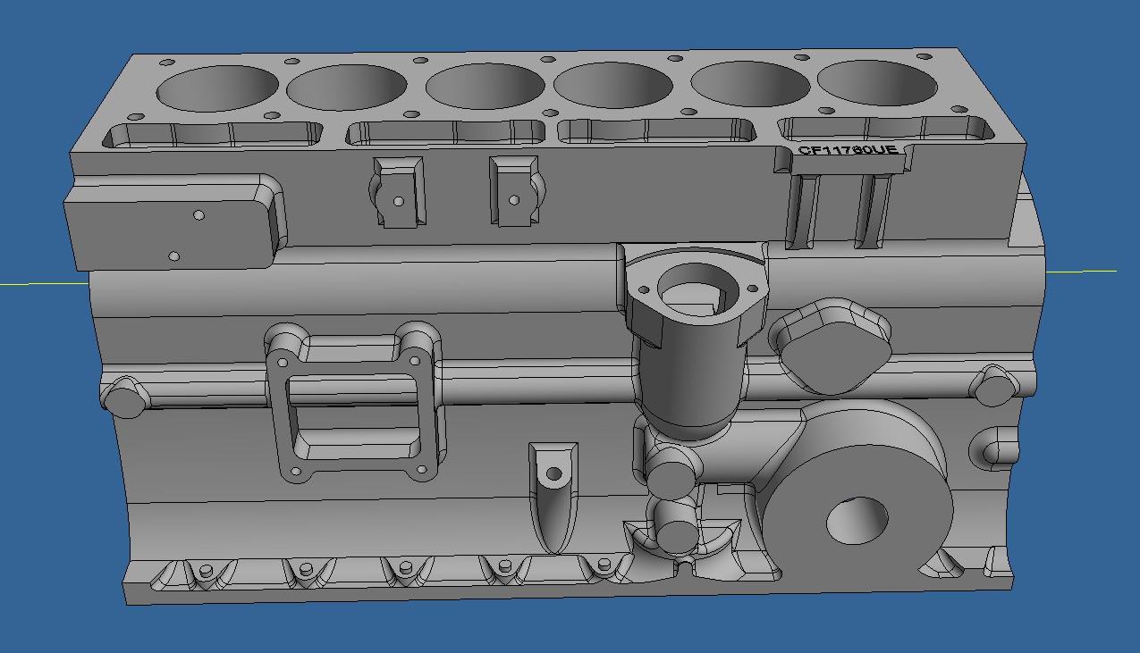
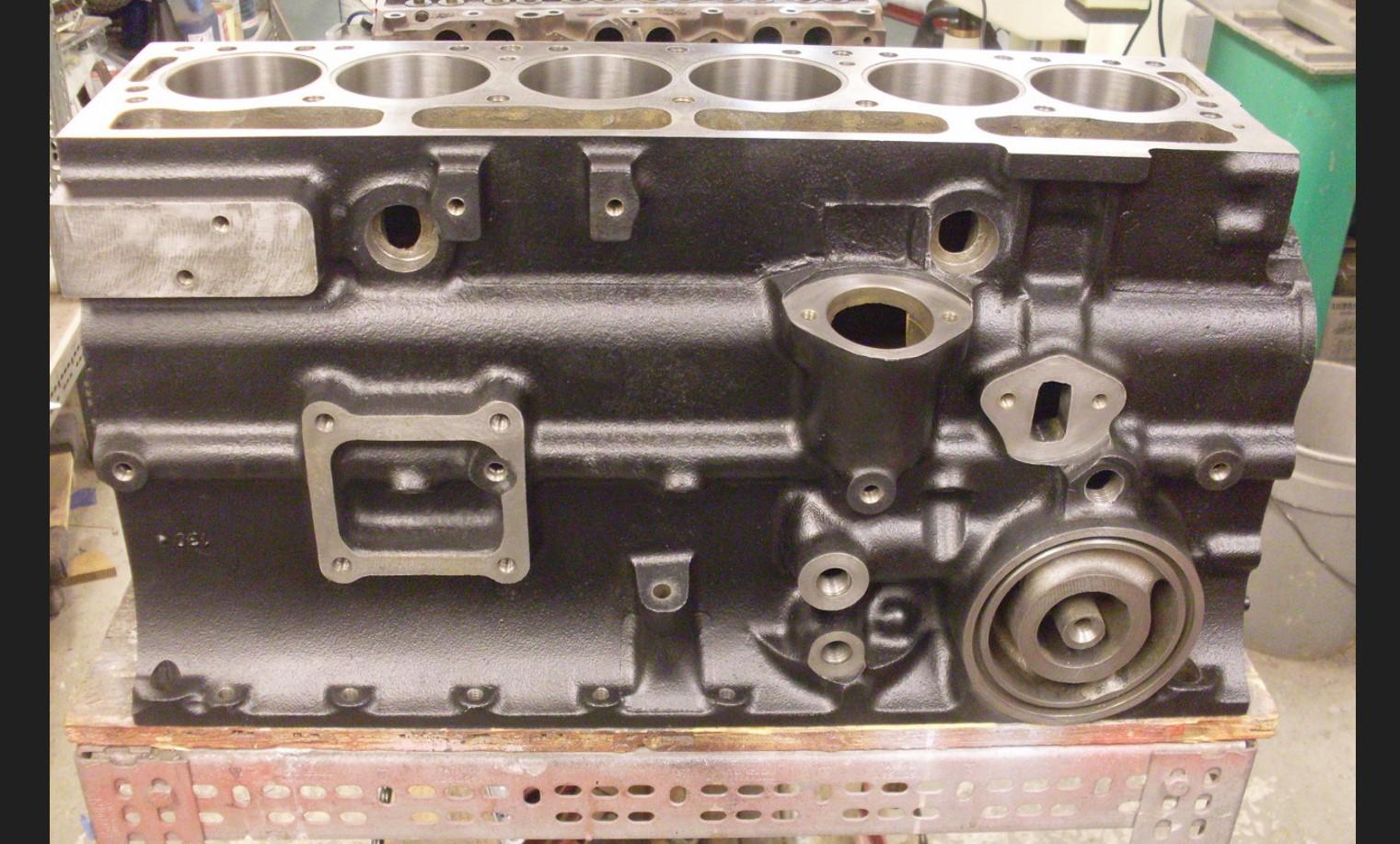
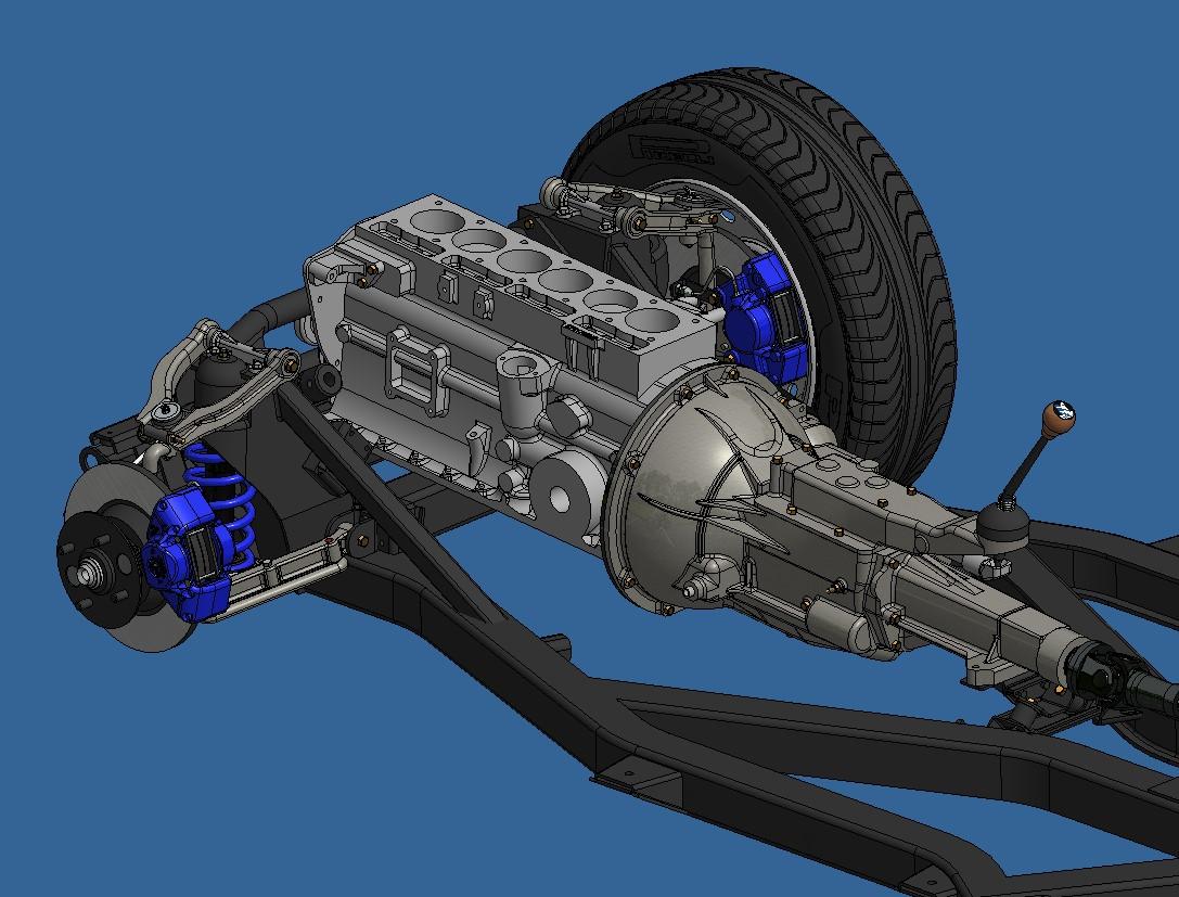
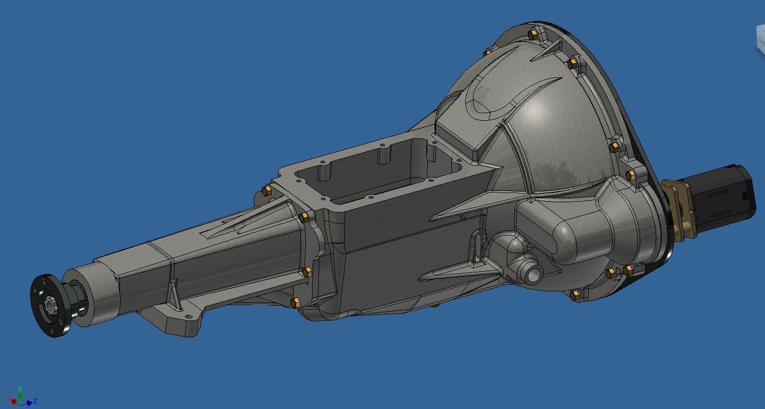
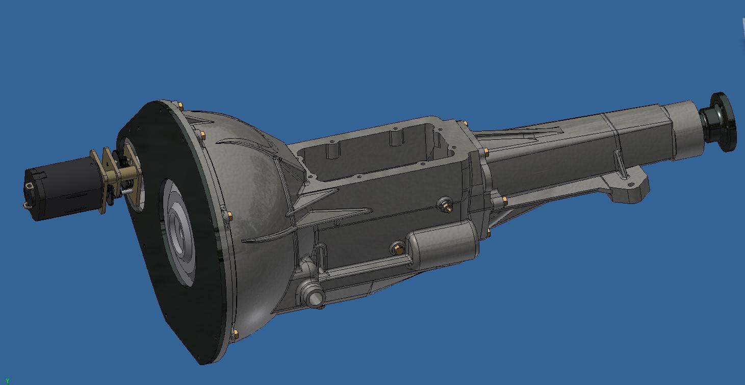
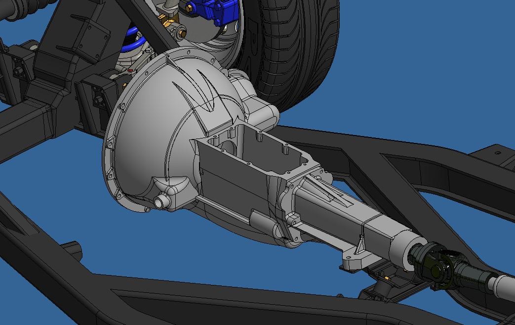
A few things happenned since monday, I turned 62 yesterday so that's a start. And after 58 years of skiing, I finally got to ski on my birthday, yeah for that! On the Tr6 front, I finished modeling the transmission, the clutch and the shifter that will actuate the clutch. I also finished the starter motor with the gearmotor hidden inside. Then I started the real meat, the engine bloc. It's about 95% done and 95% accurate. Like any engine bloc, it's a pretty complex part with lots of features. I took a few libertys such as adding ball bearings at the front and rear of the crankshaft. Aside from another Tr6 nerd like me, I don't think anyone will see the 5% innacuracy. I'll slowly model all the add-on parts but there are a bunch so might take a while. I would like to have a rotating ignition rotor in the distributer just for the fun of it. I'll see if it's possible but since the distributer takes it's power from the camshaft and I plan on having a rotating camshaft, it should be doable. Completed clutch mecanism 20251125_212837.mp4 Starter motor With hidden gearmotor Almost completed bloc Vs a real one 20251128_195906.mp4 And on the frame
-
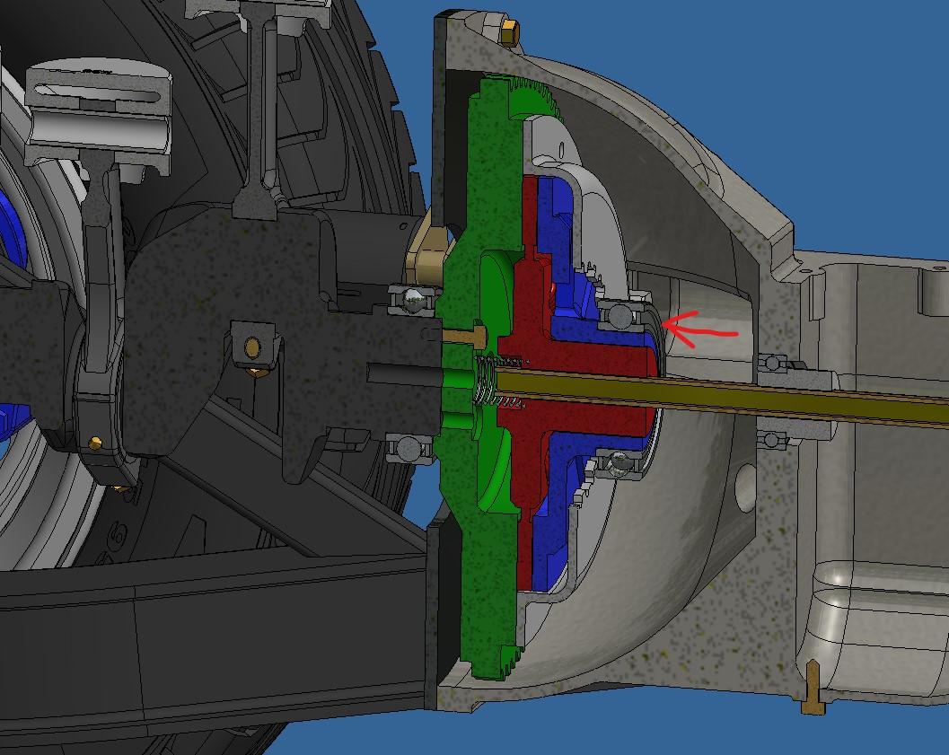
I did the crankshaft today, it went pretty well. 20251124_211253.mp4 I also started on the clutch. Unlike on the hydra where I had a geared coupling hidden inside the transmission to drive the rear wheels and that didn't work well, I intend to drive the rear wheels using a dry clutch just like on the real car. Here's how I see it. The green part is the flywheel and it is bolted to the crankshaft so when the engine turns, the flywheel turns. In red is the clutch plate and it is coupled to the main transmission shaft that drives the wheels, it can slide on the shaft and has a spring pushing it off the green plate. The blue part is the clutch pressure plate that turns freely around the clutch plate (red). The idea will be to push the blue part against the red part that will in turn push against the green thus transmitting the torque from the engine to the wheels. I still need to figure out how to push the blue part by using the gear shifter. Aside from the 'using the gear shifter' bit, everything else is basically how a real clutch works minus a lot of fancy springs, shouldered rivets and a bunch of other stuff. I will probably make a cut-out of some sort under the bell housing so that all this stuff can be seen.
-
For those of you who work with computers, you know that eventually something will go wrong. Well something did go wrong will my bell housing 3d model. After close to 8hrs of work, the file decided to become corrupt and could not be opened anymore. It's a very complex part to do so redoing it wasn't all that fun. The good side of this is that it went faster the second time around and that I'm more pleased with the result. Bell housing V2. You will notice that the gearmotor has been placed where the starter motor normally is. Being a 1/6 scale model, I should have enough space inside the starter housing to hide the gearmotor. I also started work on the engine, I did the pistons. On a lighter note, I went to a model show last Saturday and picked up 3 prize. I brought the Hydra Coupe and the bentley blower. Both cars were in different categories which had close to 30 entries each. The bentley won first place in the 1970 and older cars segment while the hydra won first place in a movie vehicle themed segment. Plus, the Hydra won best of show!! It was a nice day.
-
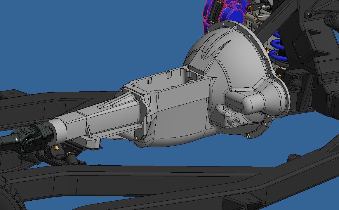
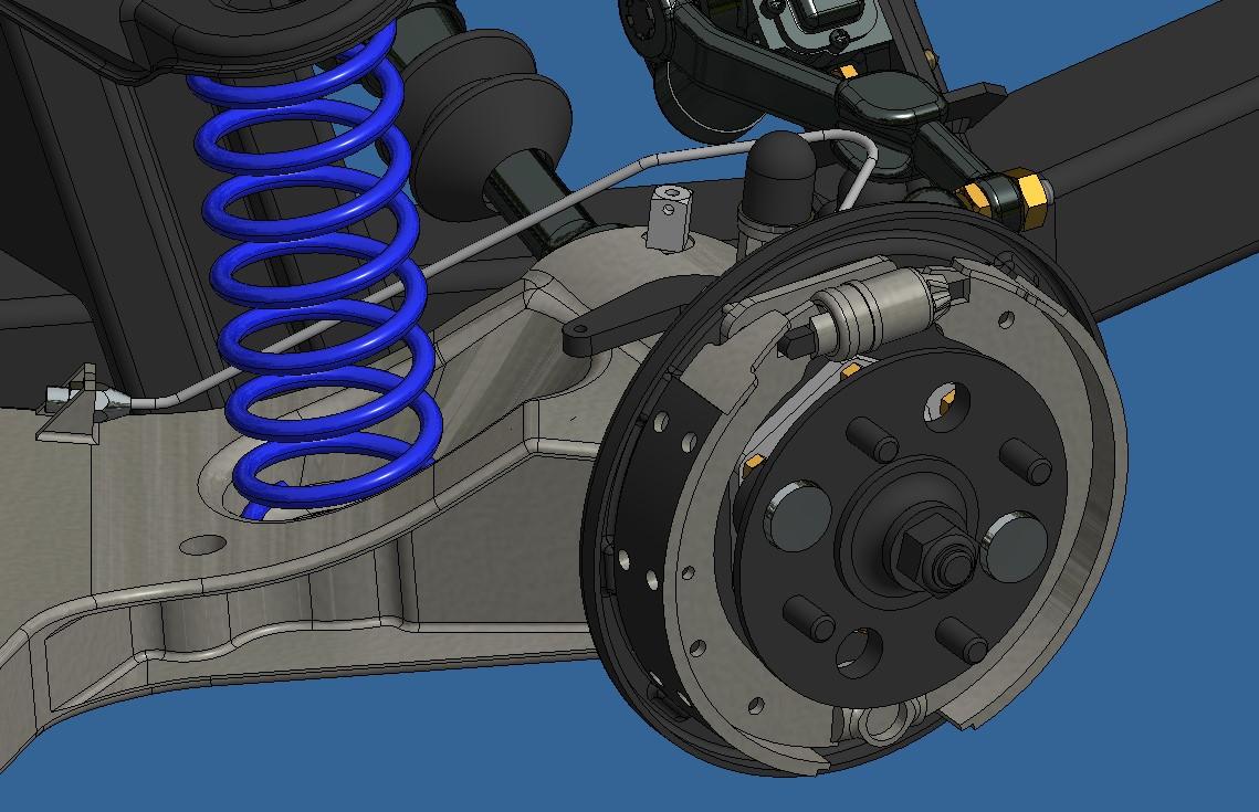
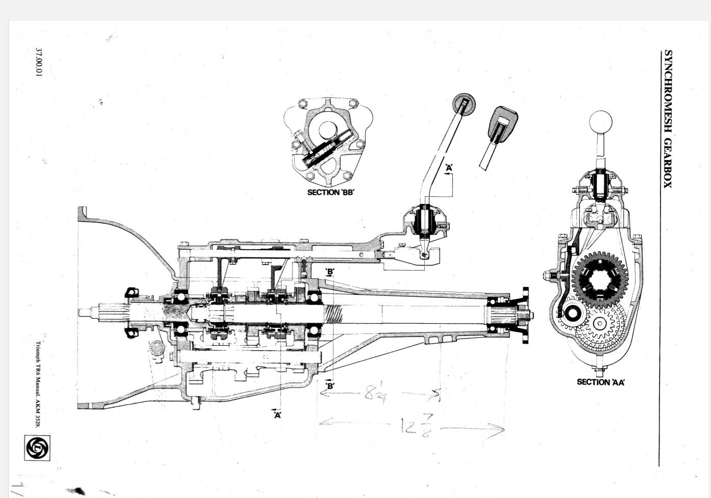
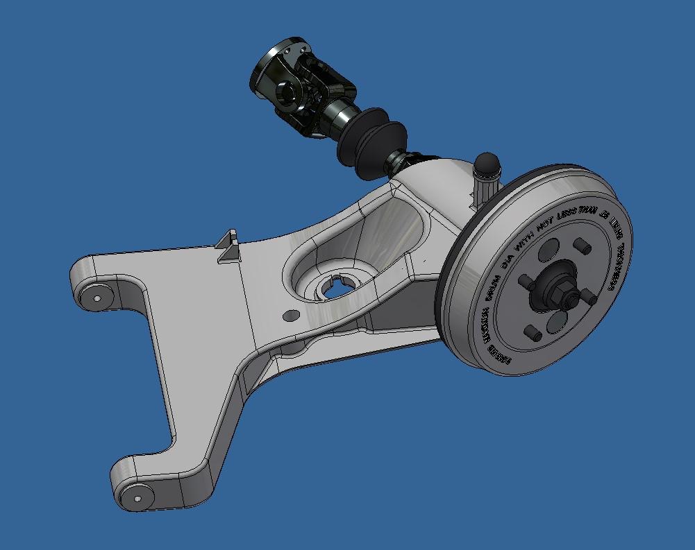
With the differential done, I'm slowly progressing back towards the front of the car. I did the rear brakes and started the transmission housing. It's composed of 3 parts. The tail housing, the bell housing and the shifter housing. Having restored this car for real, l have a ton of literature. One of these books (the tr6 maintenance book) is full of really nice hand made 3d drawings (remember that it dates back to the pre-computer era) and some just as nice cross section views. There's one of the transmission that I used to 3d model it. Combined with pictures from the net and measurements from my car, I was able to do a decent job of it. It's not finished but not to far either. I still have the complete shifter housing to do. On the hydra, I made a mecanism activated by the shifter to engage the rear wheels but it didn't work well. For this one, I would like to make the actual friction clutch and engage it using the shifter instead of the clutch pedal. Cross section from maintenance manual 3d model of transmission so far the transmission from my car after it was restored And the rear brakes
-
Thank you Bainford. A miniature working differential is actually quite common in the rc world (which I am not into). The difficulty here is to keep it to scale an to not oversize everything. It's relatively easy to do since, contrary to rc cars, my models are for show only so not subject to impacts and rough handling.
-
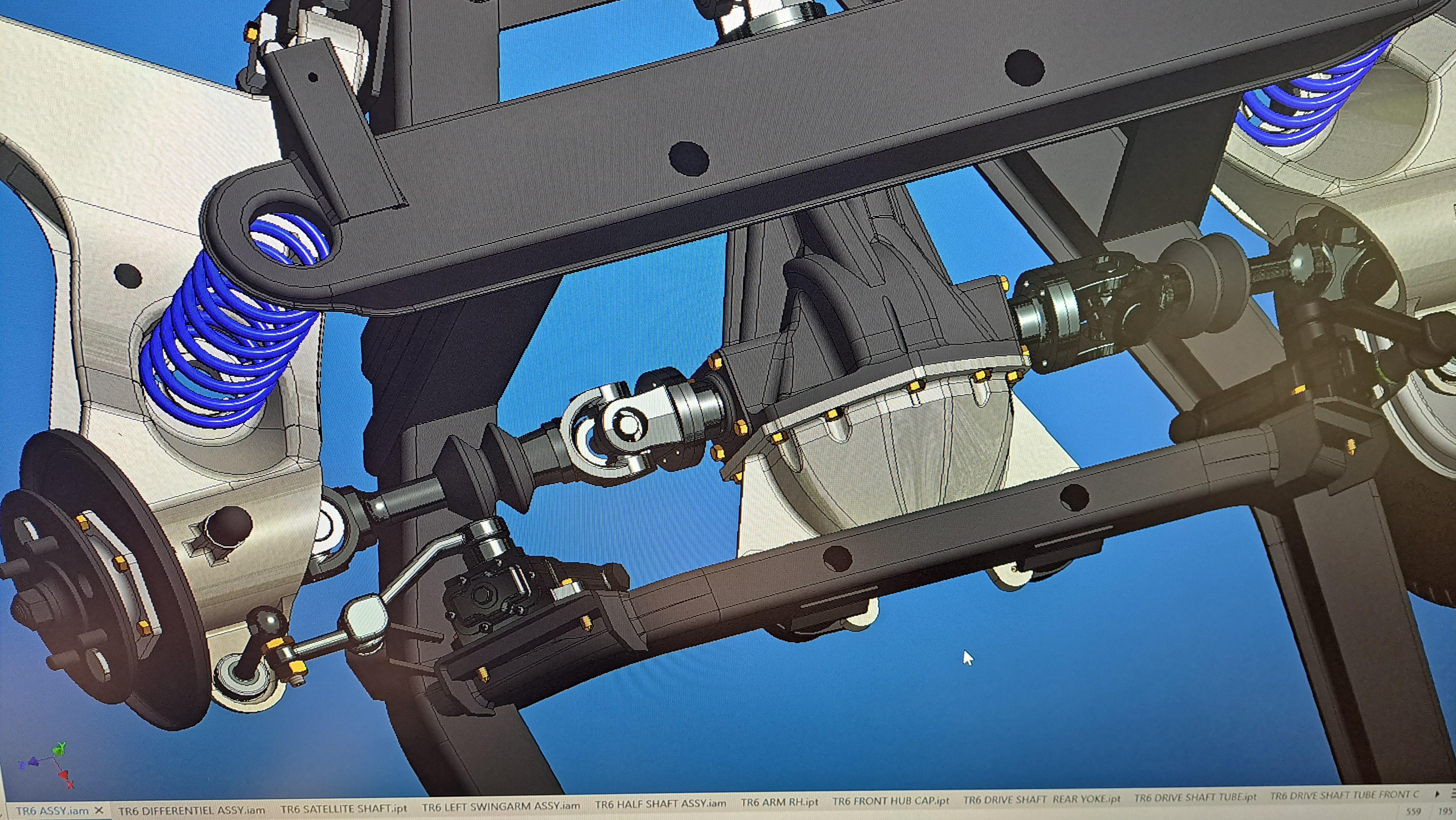
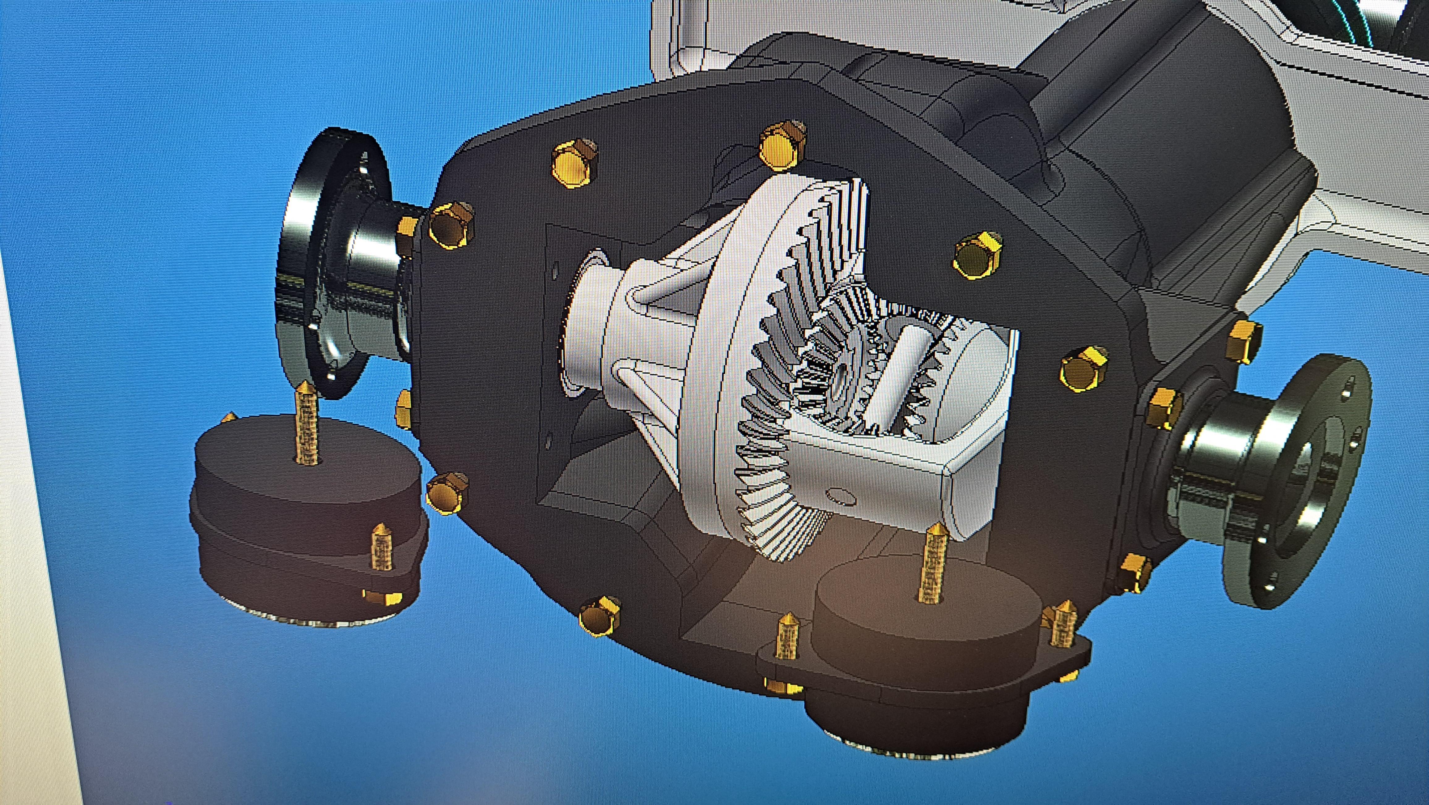
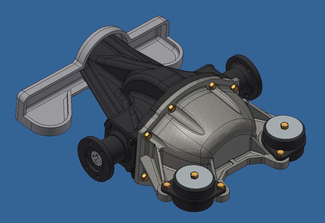
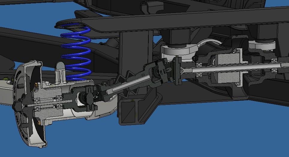
Yesterday I said that I would not be making a real differential, well I lied. I decided to try and see if it could work. So today, I designed the internal components that makes a differential do what it does which is to drive both wheels while permitting the wheels to rotate at different speeds. It's a beautiful feat of engineering invented back in 1827 by a French guy named Pecqueur. I also redid the half shafts with more accurate universal joints along with the drive shaft. I incorporated the small bearing (which I received today and boy, are they tiny) in the front hubs. I had to find slightly larger bearings for the differential, I went with 4mm id instead of the 3mm id used in the hubs. Redesigned half shafts Differential internal bits Working differential (in cad at least) 20251117_194827.mp4
-
I started this project stating that I wanted a running engine and drive train as I did on the Hydra. I would also like it to be a better design. The hydra motor broke, yes because the weak point was the crank but also because there was a lot of friction from the different rotating components. So I'm trying to reduce this friction by using ball bearings wherever possible. I'll have then at the rear hubs, inside the differentiel, the transmission and, if possible, the engine. I bought a bunch of 3mm id x 7mm od x 3mm thk bearings. With this in mind, I 3d modeled the rear drive train and differentiel today. It's not 100% finished but it's close. Inside the differentiel, I'll probably use the same setup as I used on the hydra which means it's not a real differentiel but rather a 90 deg gearbox. I also finished the trailing arms, I got them looking a lot more like the real ones now. Almost finished differentiel Trailing arm with drum and half shaft cross section of rear drive train with bearings in place (not final yet)
-
Unatural, it's actually for both reasons I'm looking. I already went through 1 LCD screen and ever since I changed it, I find that it doesn't print as good as it used to. I often tried to print at a thinner layer height (25um) but never got good results and frankly, my prints are fine at 50um. I know they could be better but like you said, at the scales I work with... l could really use a larger print volume though. I'm looking at the Uniformation GK3 16k with the T screw. Does anyone now this printer?
-
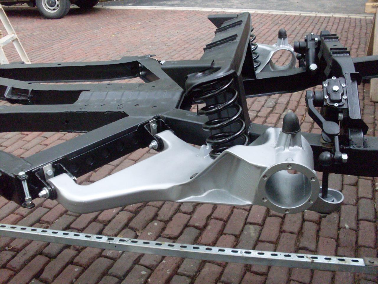
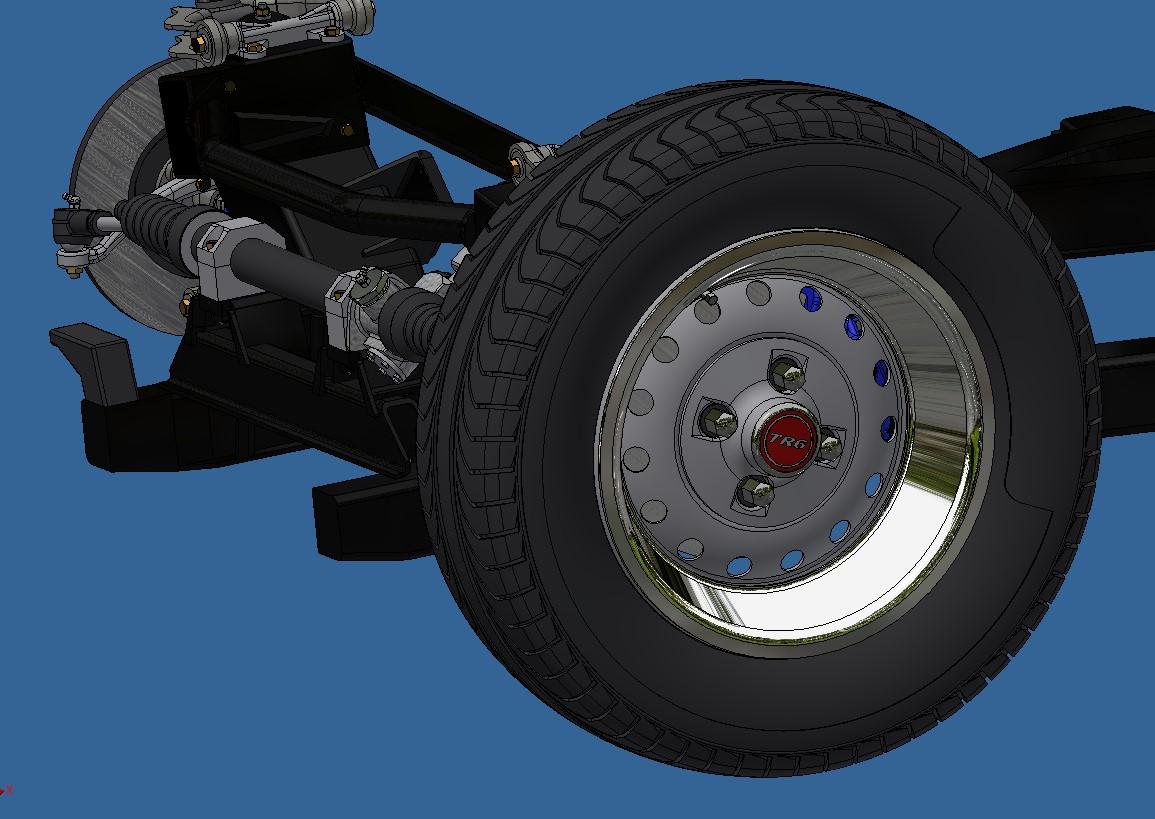
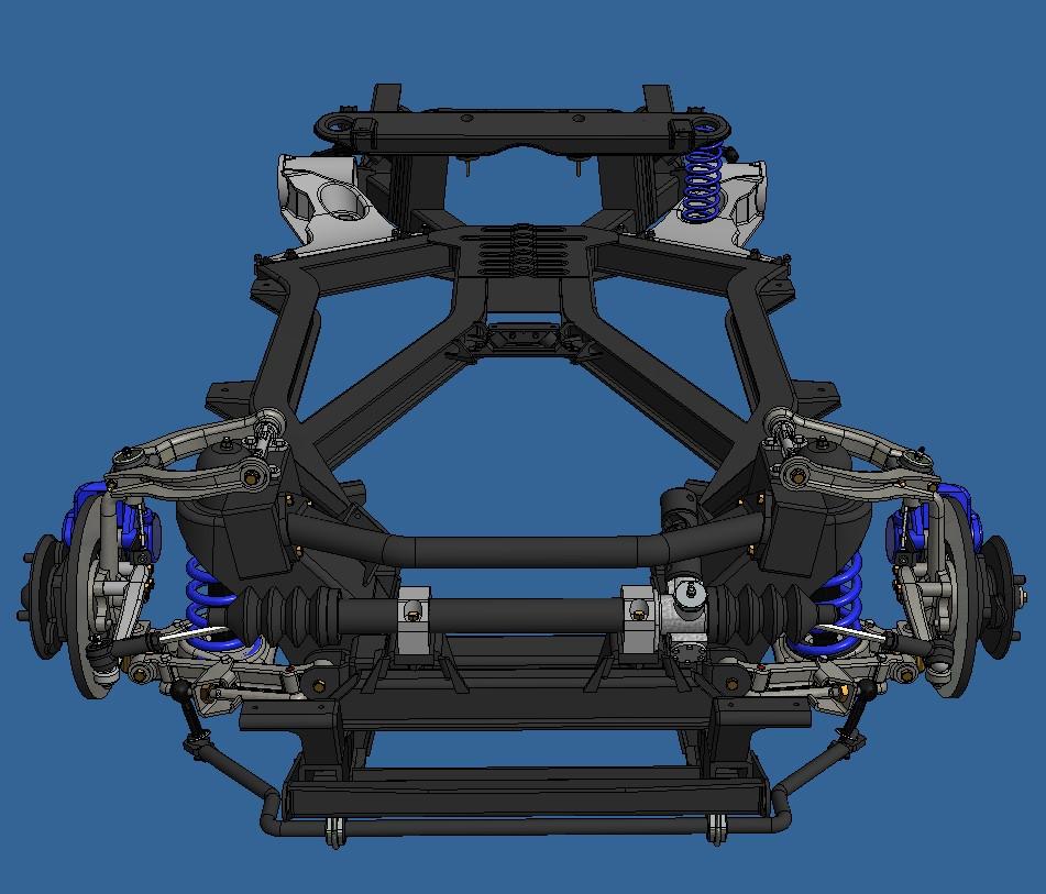
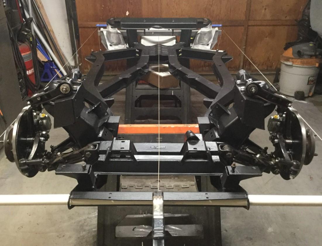
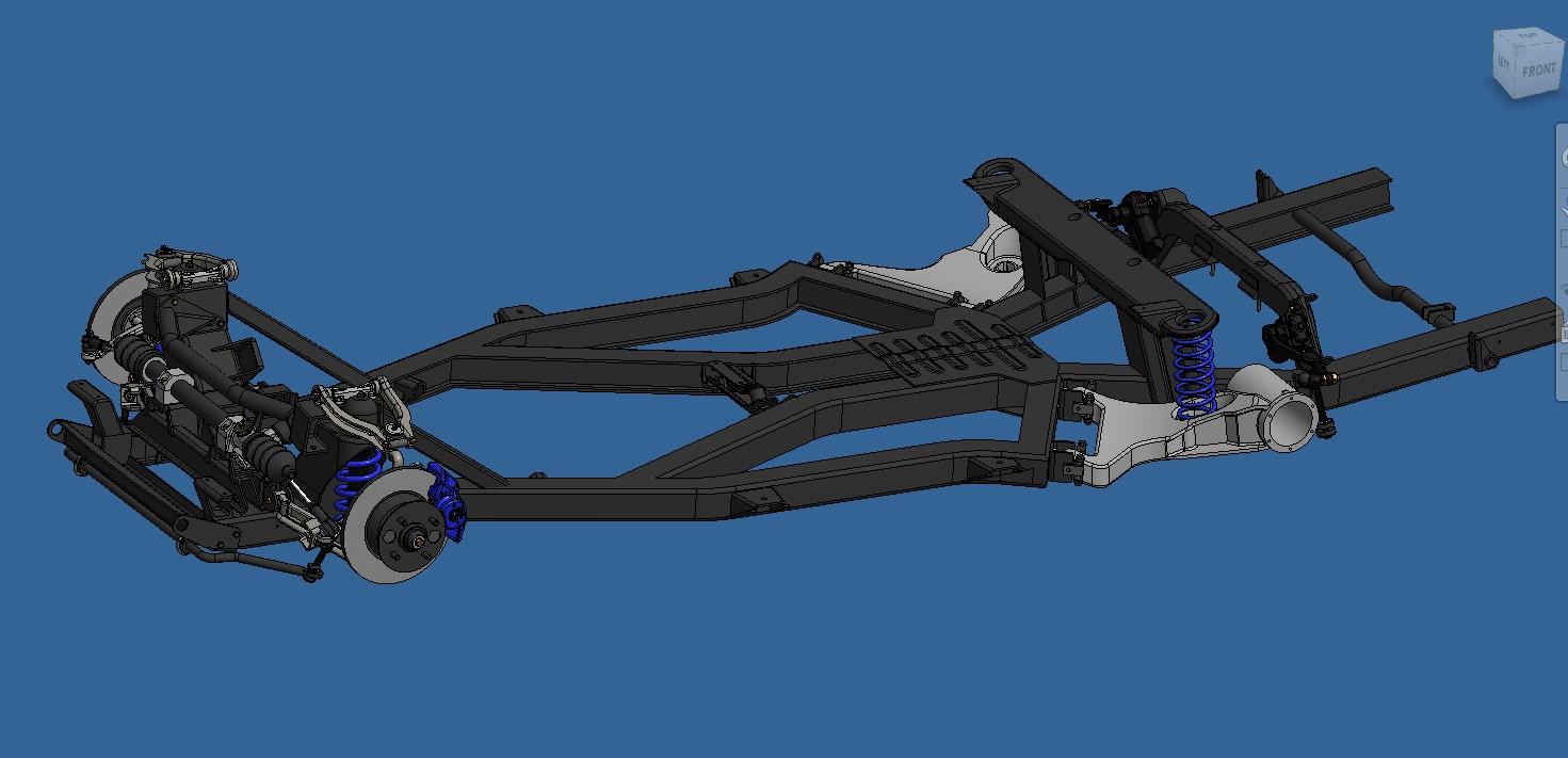
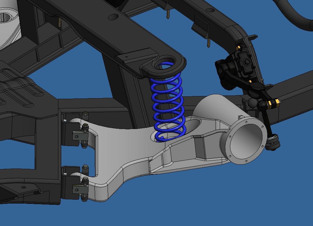
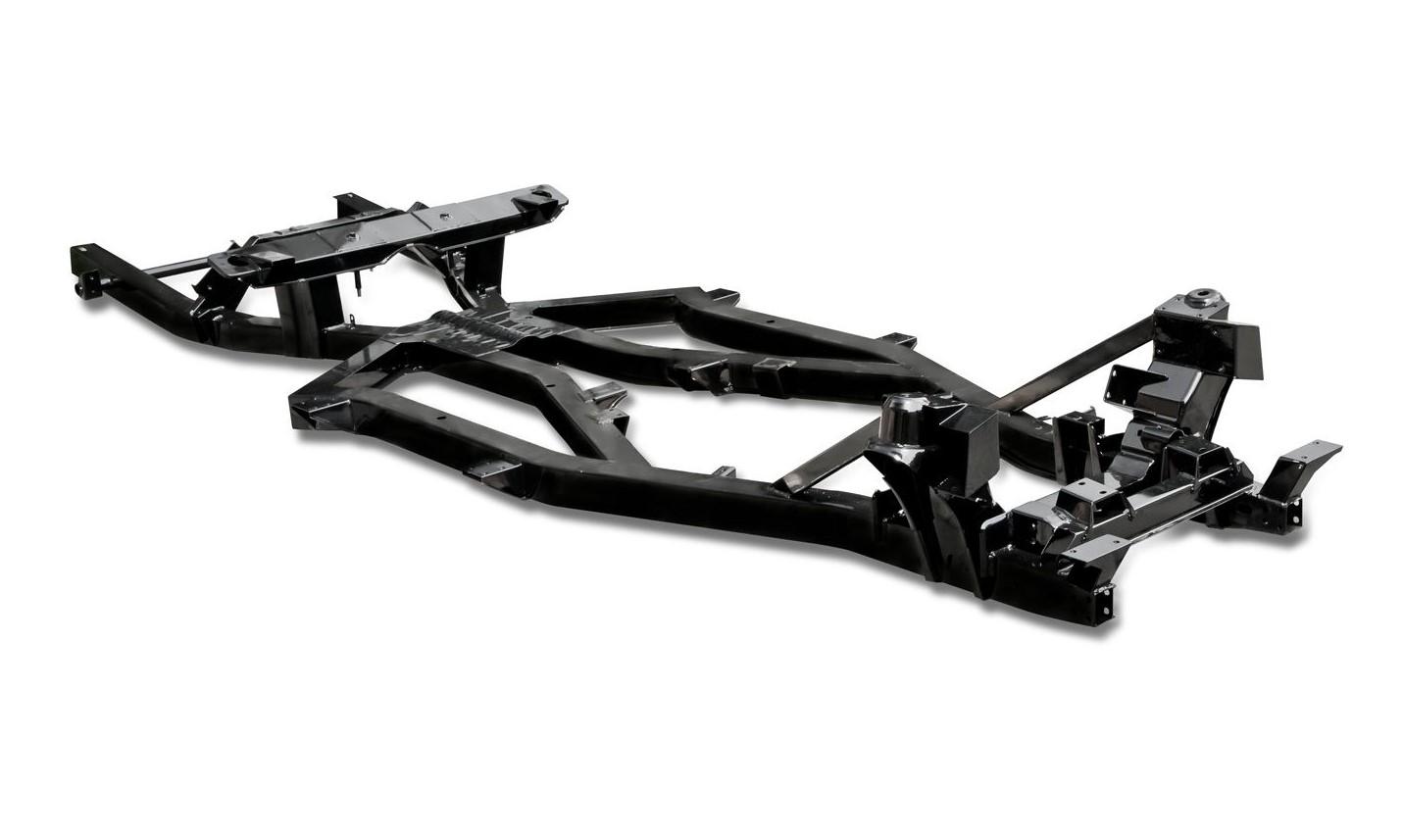
I've been busy 3d modeling the last 2 days. The frame is pretty much finished, all that is left to do is to split it in printable sections. Probably 3. I also started on the rear suspension, I have the lever shock done and am trying to do the swing arms. These are very complex parts with many planes and axes, not one being square or parallel to another. I'll figure it out eventually. The finished frame model compared to a real frame Rear suspension bits Vs real bits And an overall view Compared to the resl thing (not mine)
-
Hello Armando, very glad to see your finished model! You did a fine job of it too. Since we last spoke, I finished the Hydra Coupe and have started a new project. You can follow it here. it's a rather personnal project since I've owned such a car for close to 20 years. good luck on your next build
-
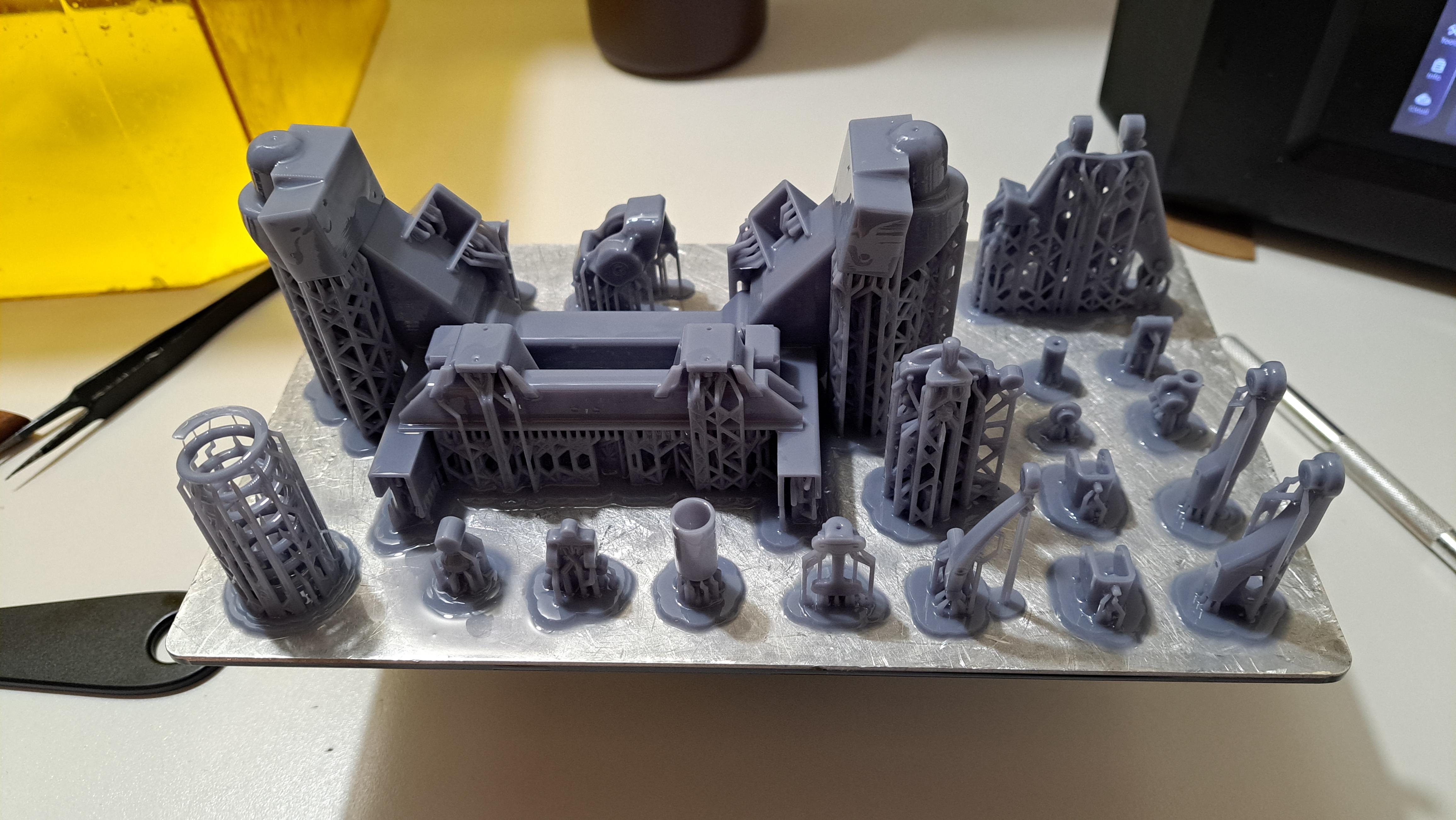
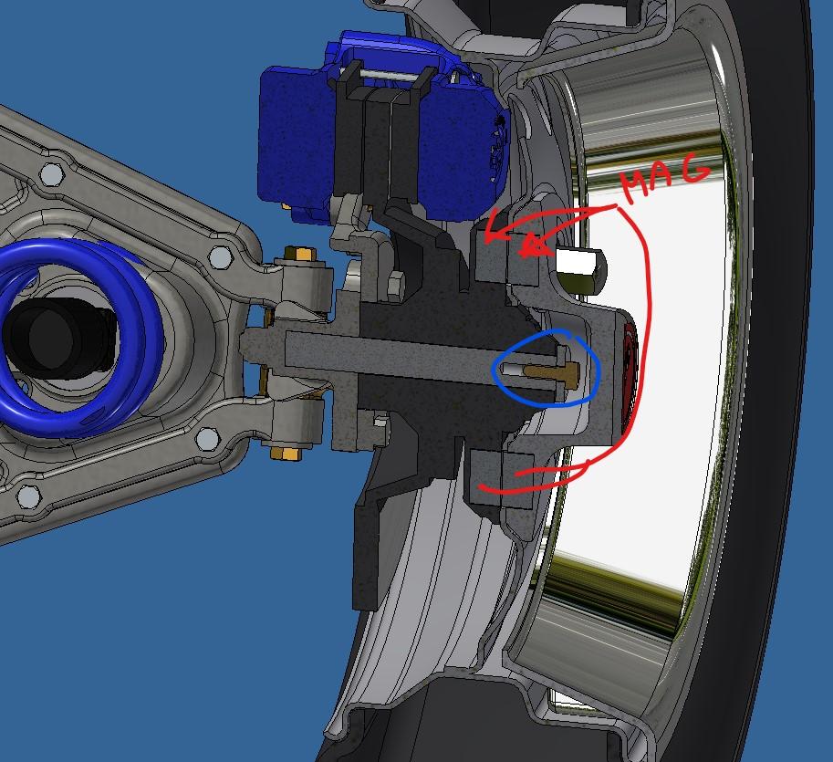
Dphipps, the magnet idea is intended exactly as you described it. Even if everything on my models work (from steering to motor to drive train) they are only for display and always on a stand. As for the printing, I use the Anycubic M5 resin printer. It's a 12k printer so the results are pretty good but I'm starting to look for something new. I see that there are 16k printers out there. We'll see...
-
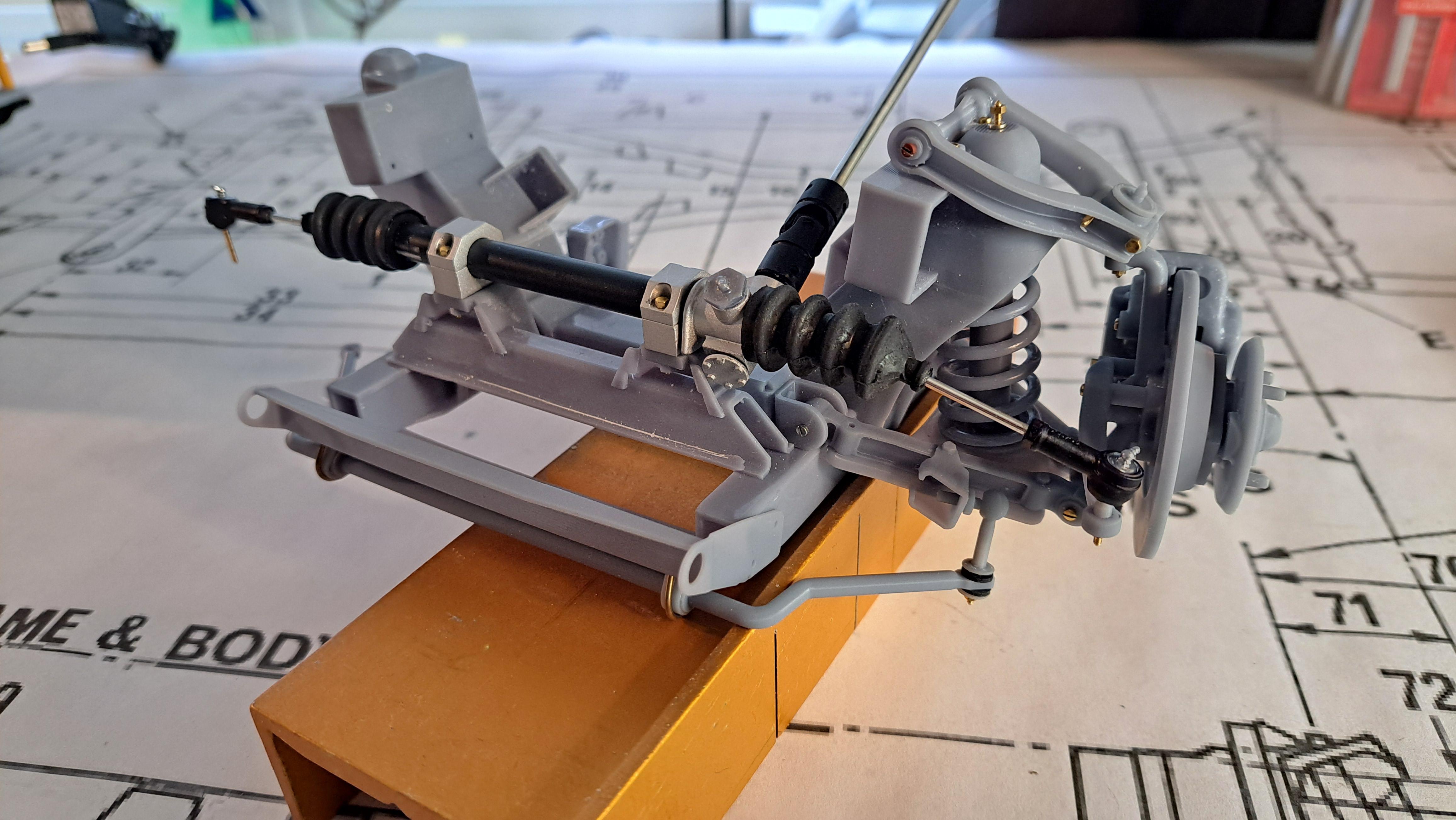
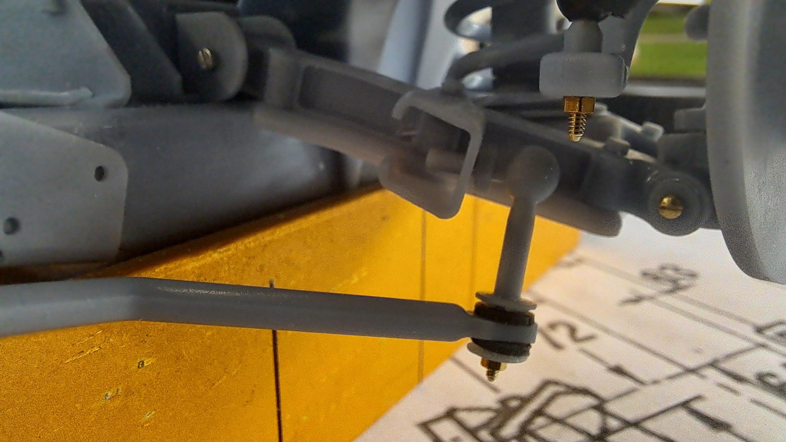
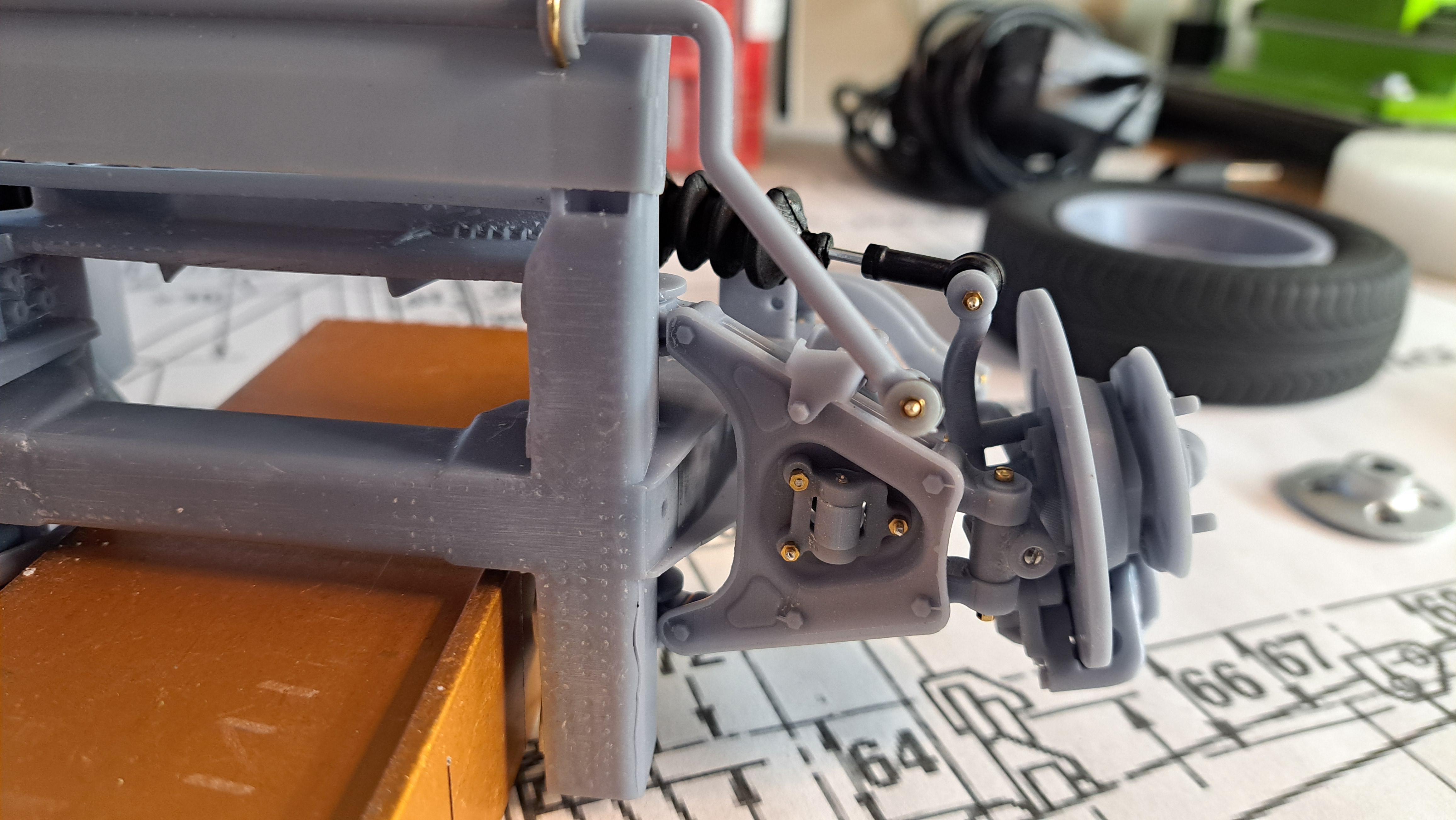
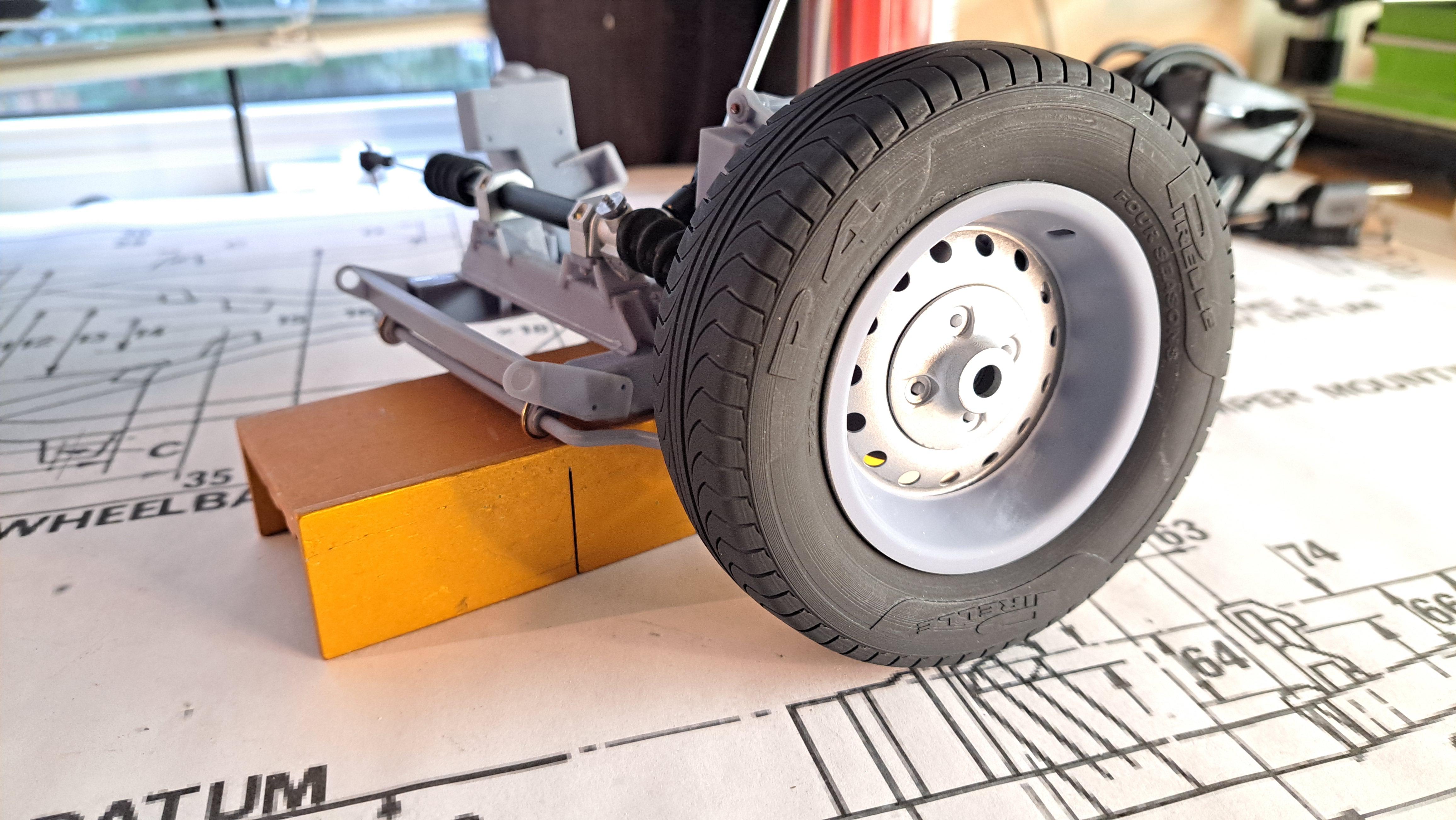
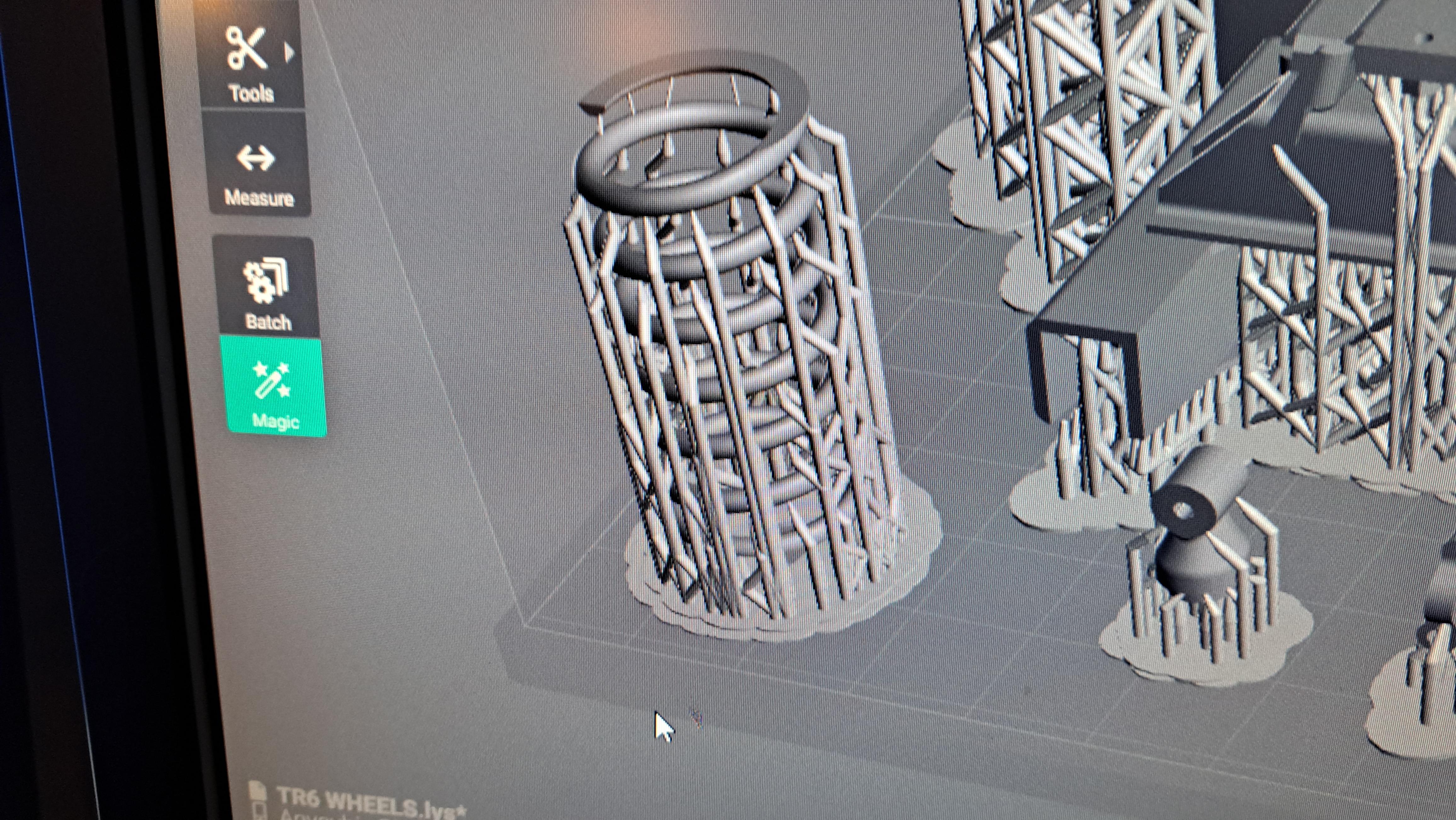
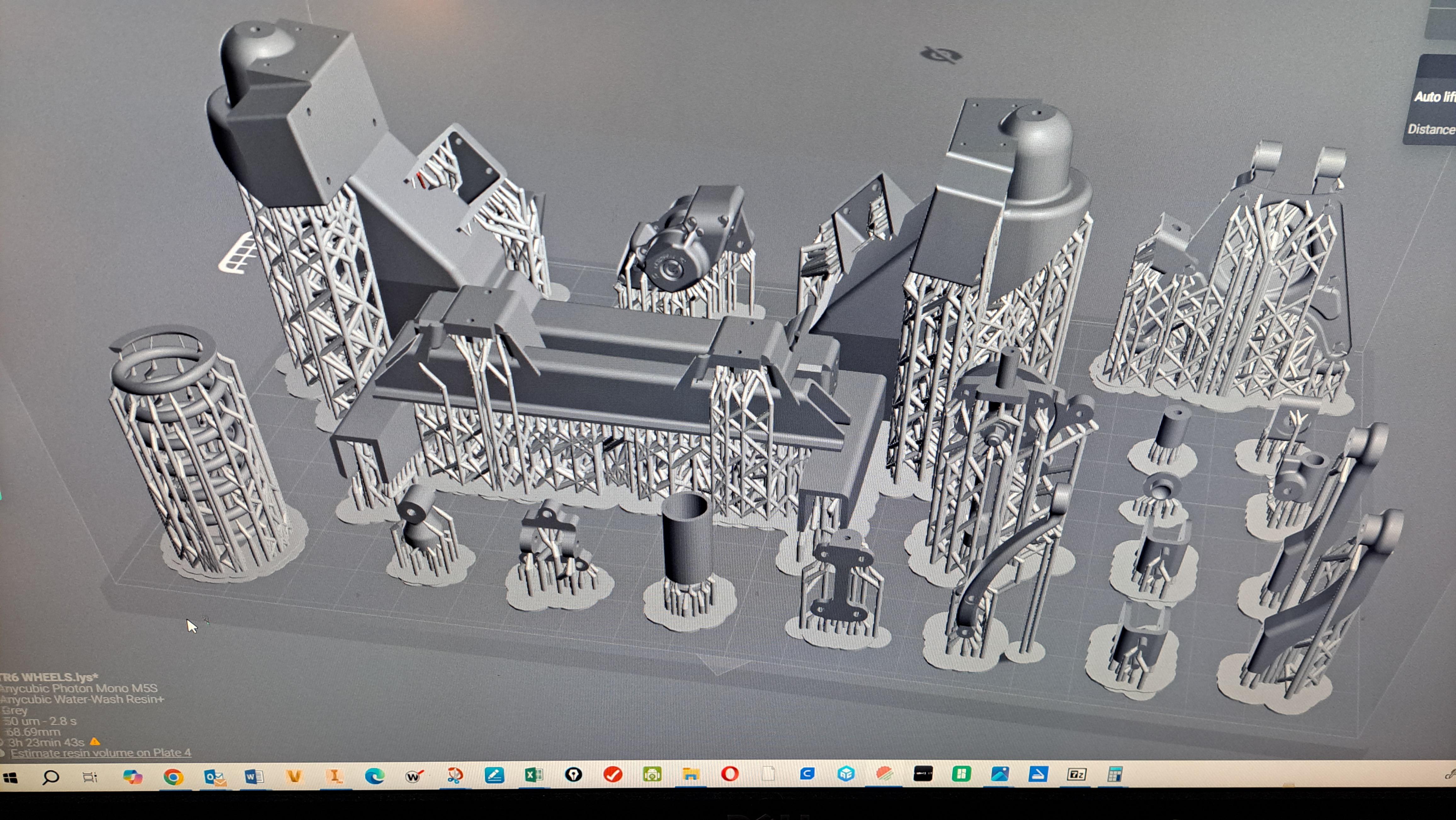
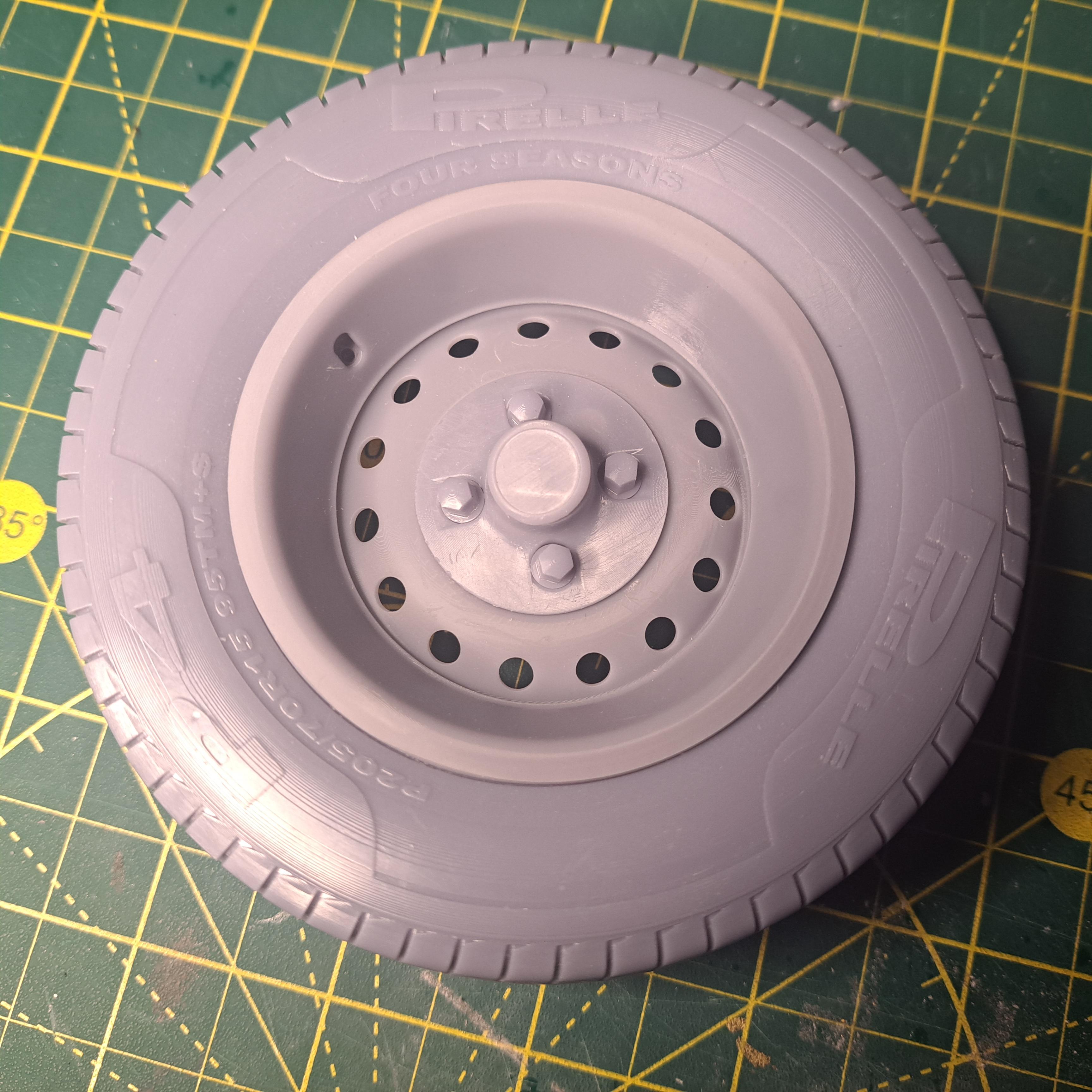
Ok, so here's where I'm at. I test printed the drivers side suspension components along with the from portion of the frame. Everything went together fairly easily, didn't have to make many modifications. I did have to hide a secondary compression spring inside the shock absorber since the printed coil spring is too weak. I'll probably end up using real springs instead of the printed ones. I just need to find the correct size. Remember, this is only a mockup so nothing is sanded or finished. I just wanted to confirm that the geometry was ok. I also painted a wheel to see what it looks like but again, only a mockup. I didn't paint the ring yet since i'm out of chrome paint. I ordered a new type of chrome paint from Green Stuff, apparently, it's more touch resistant then the revell. I was able to confirm that using 2 magnets to hold the wheel in place is a good idea. Here are some pictures And some videos 20251110_145840.mp4 20251110_150258.mp4
- 69 replies
-
- 10
-

-
Suspension test print seem 100% ok. I'll know for sure once everything is washed.
-
Probably, i did print some a few weeks ago for a 1/25 vega and they worked ok but again, it was just to try.
-
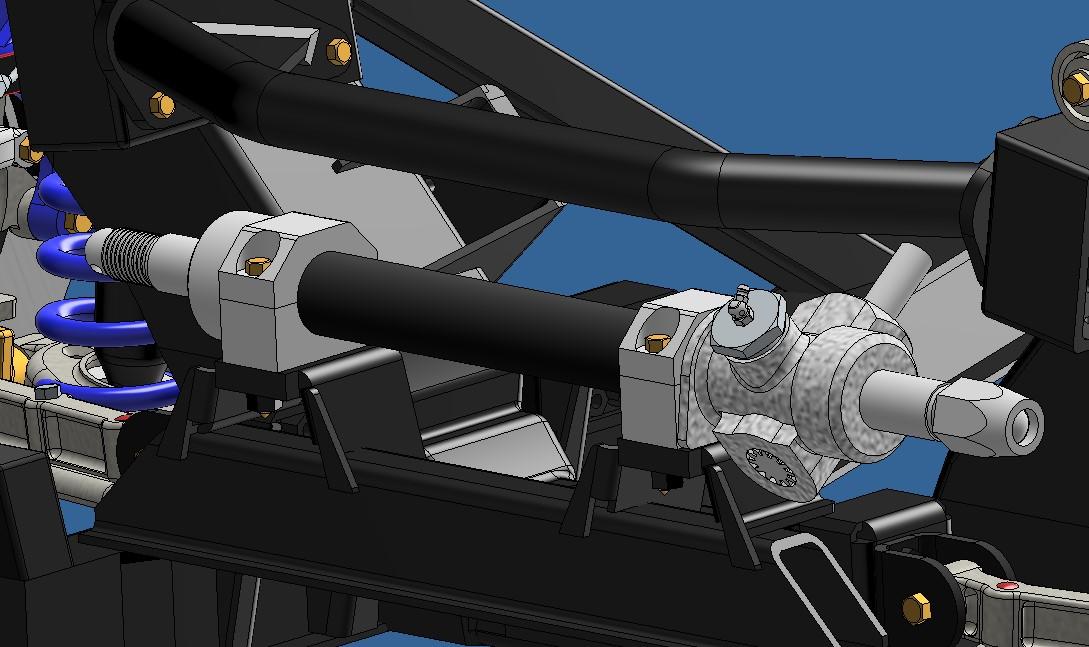
Sorry Messer but the grease fitting don't work. I did put grease on the rack before assembly. Before going further with the frame and rear suspension 3d modeling, I'm test printing the front suspension components. I'm even trying to print the coil spring. I don't expect it to work but I'm curious.
-
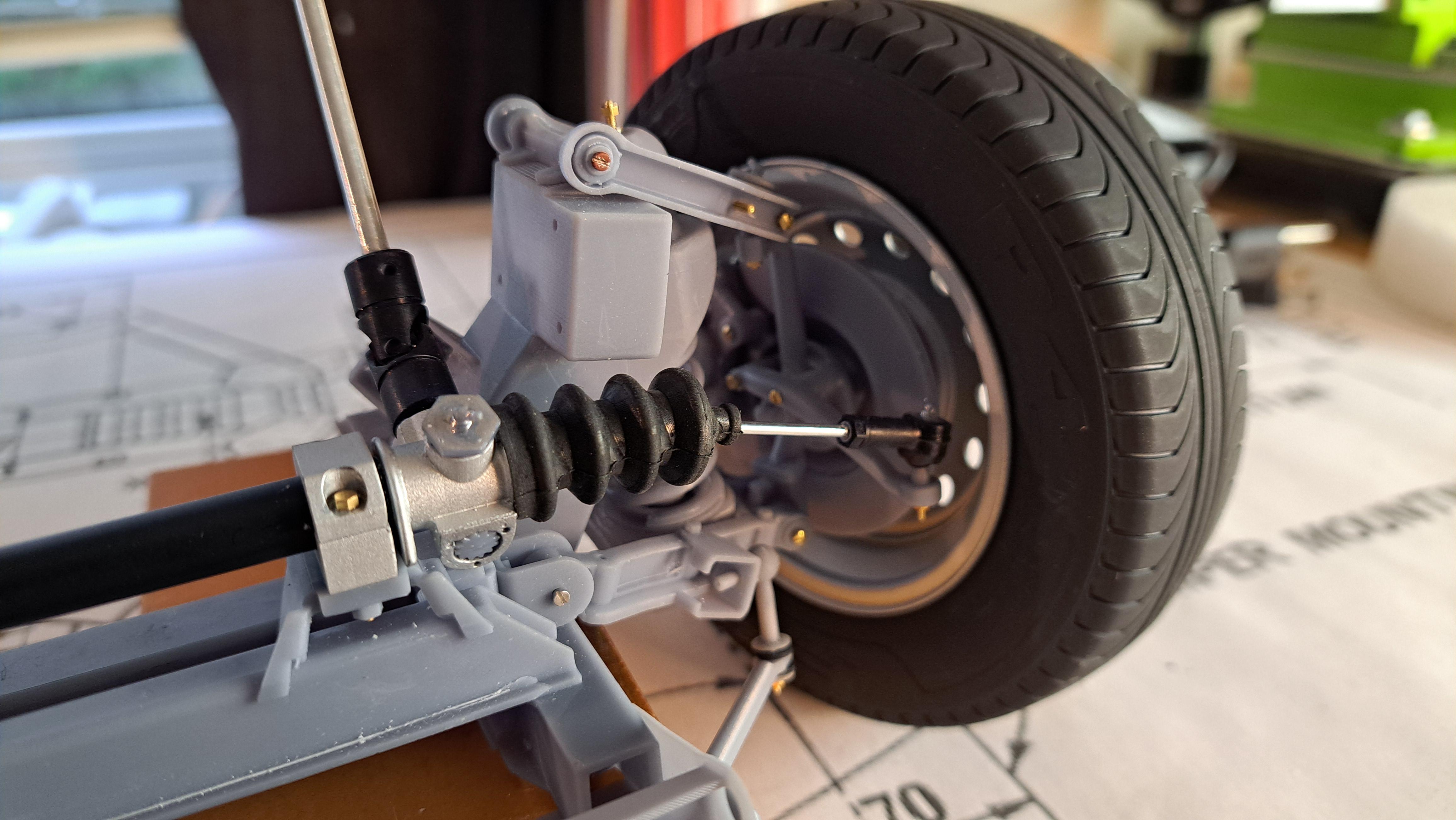
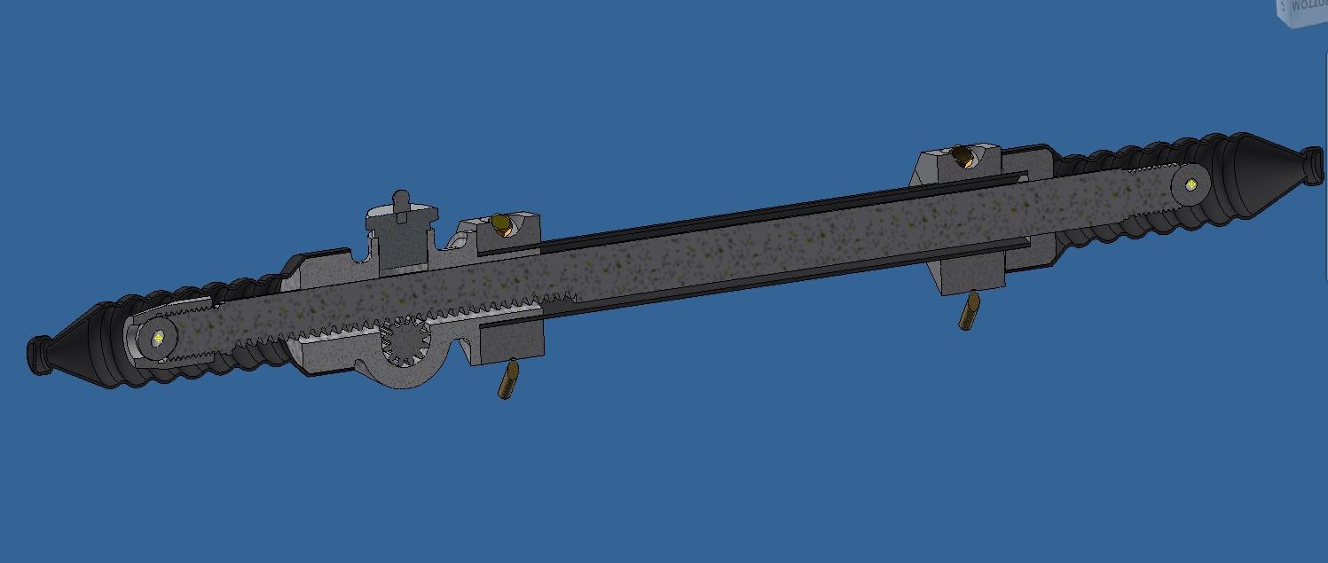
If only that was reason! Nope, just a dump typo. I repaired the typo and modified the P to look a bit more like the logo. the first sub assy is done, the rack and pinion. 20251107_140420.mp4
-
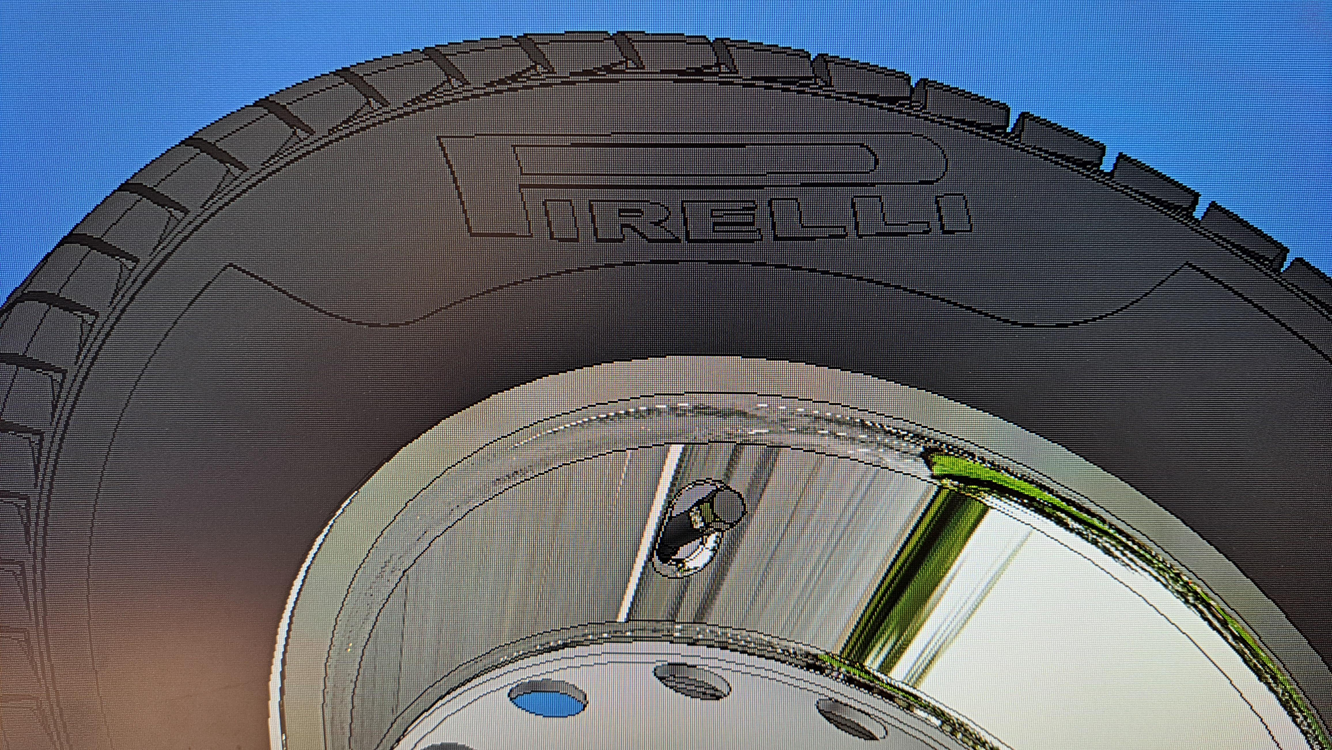
It was noted to me (thank you Messer) that I made a major typo on the tire. It's should be Pirelli, not Pirelle. Error fixed ! Sorry to all you Pirelli fans and to all english teachers.
-
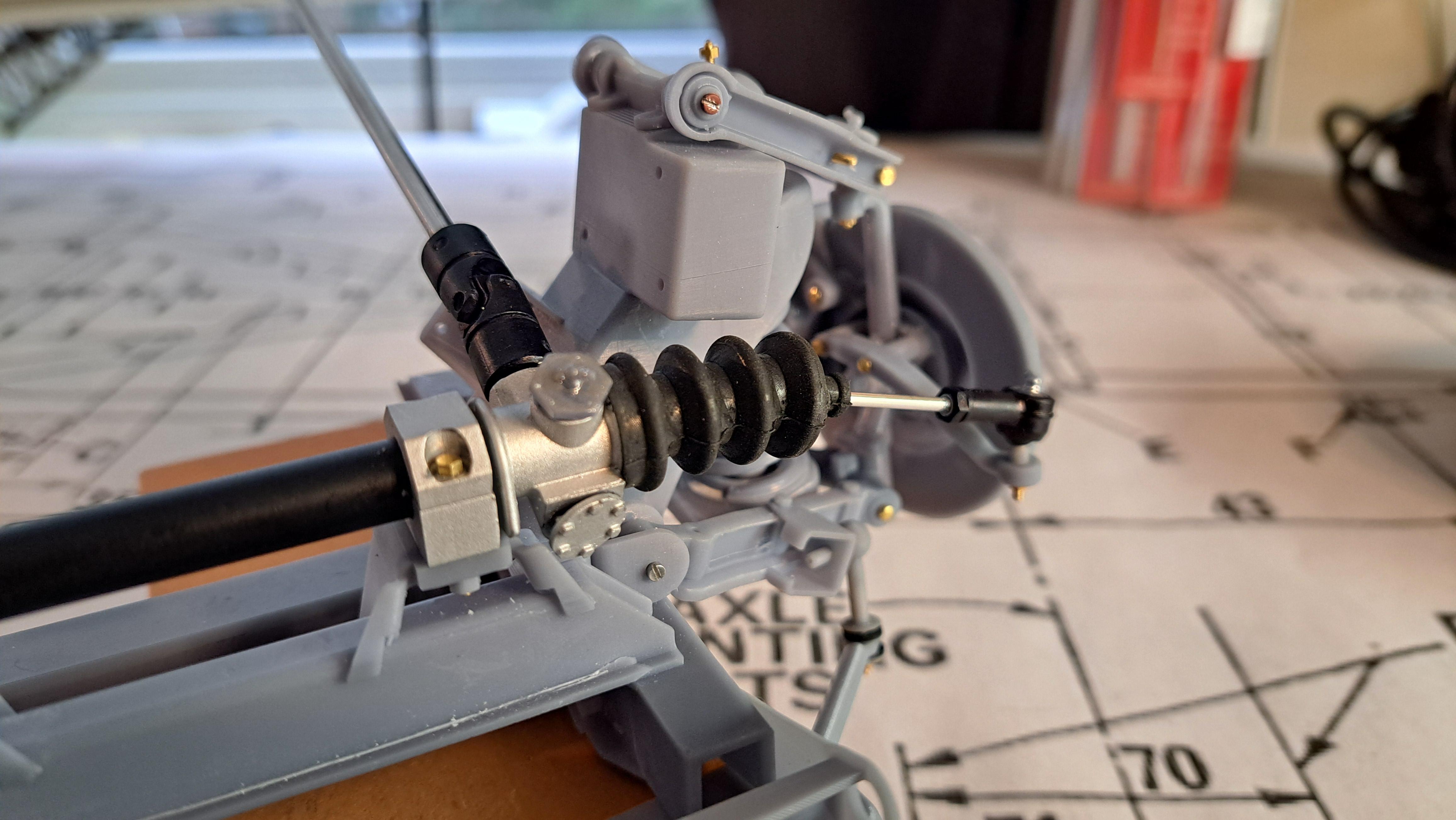
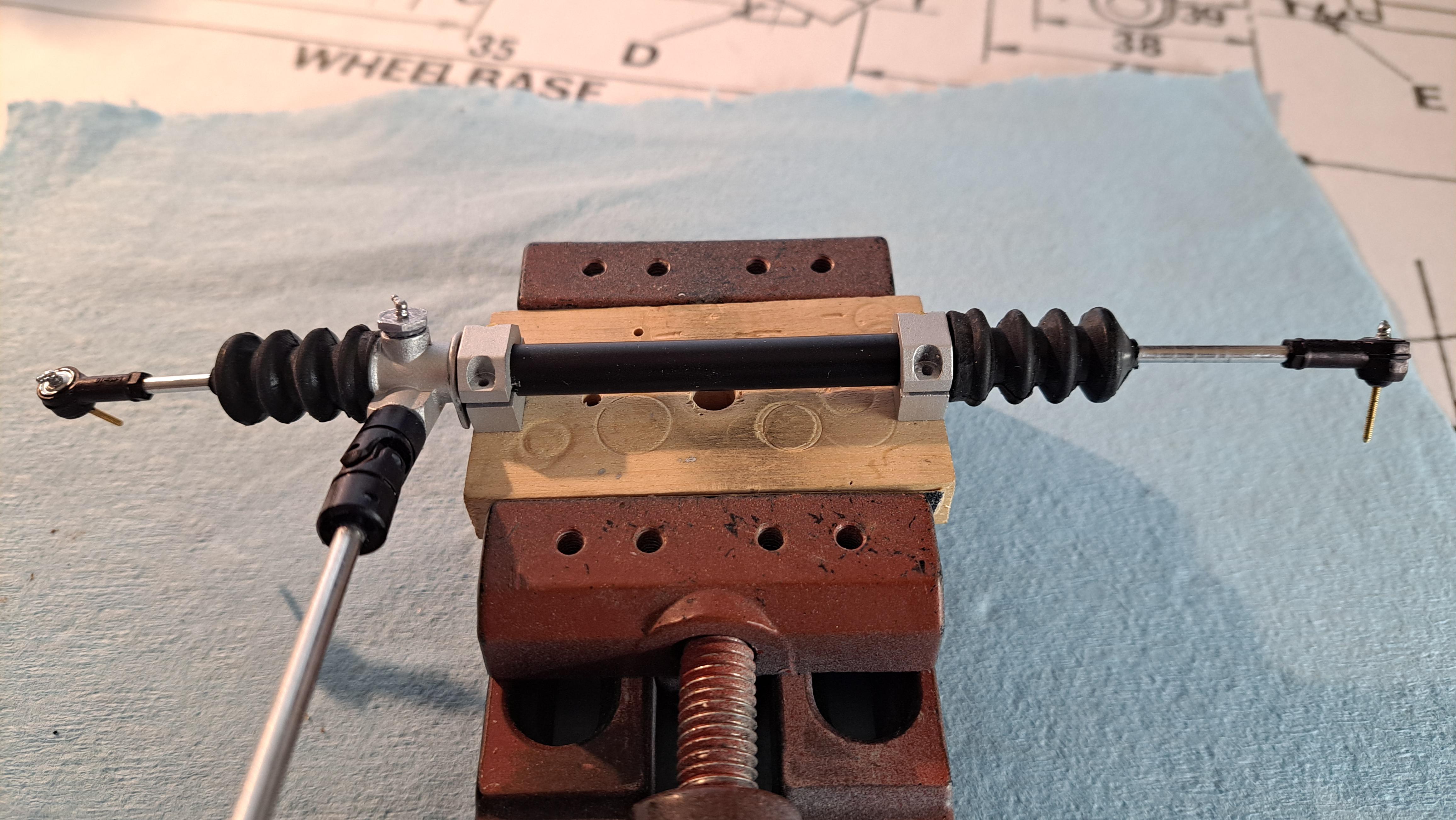
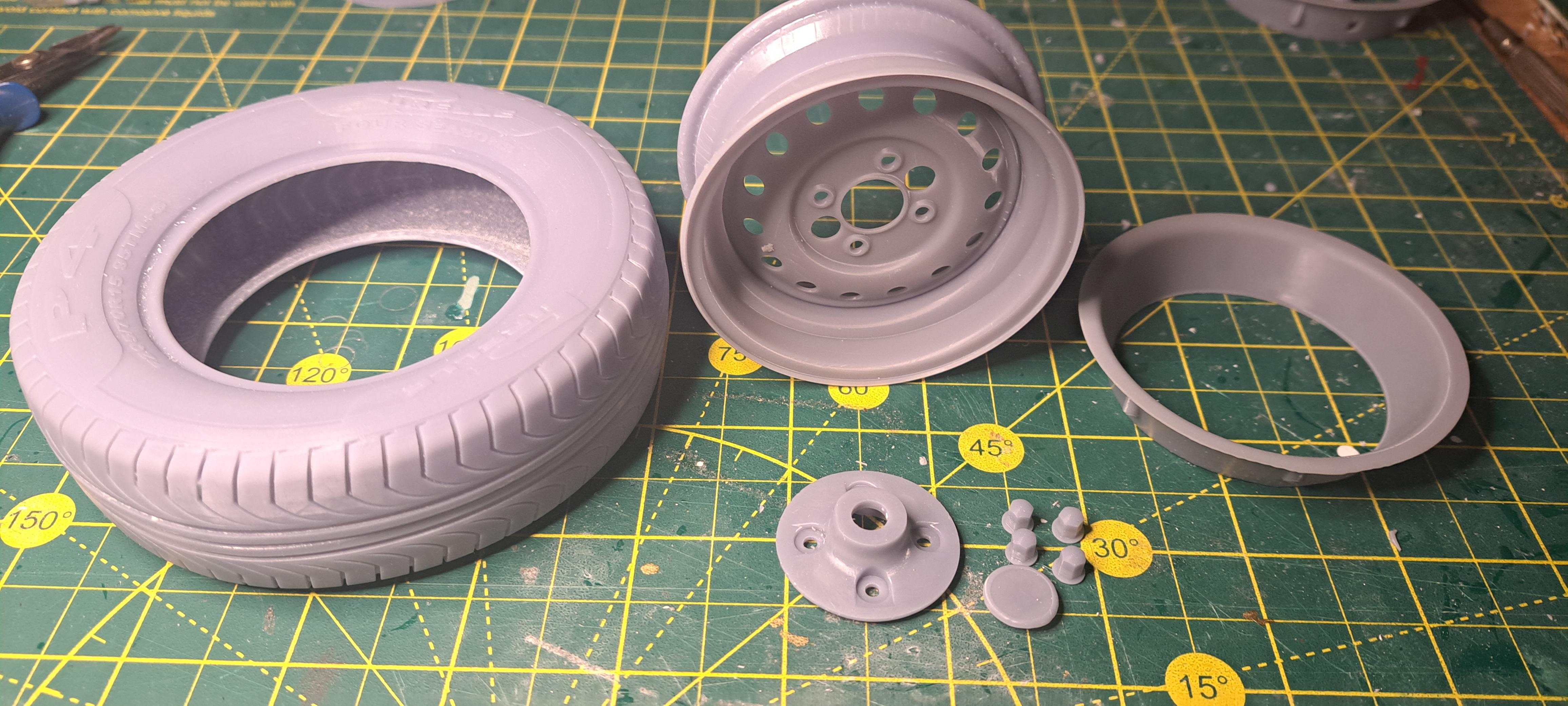
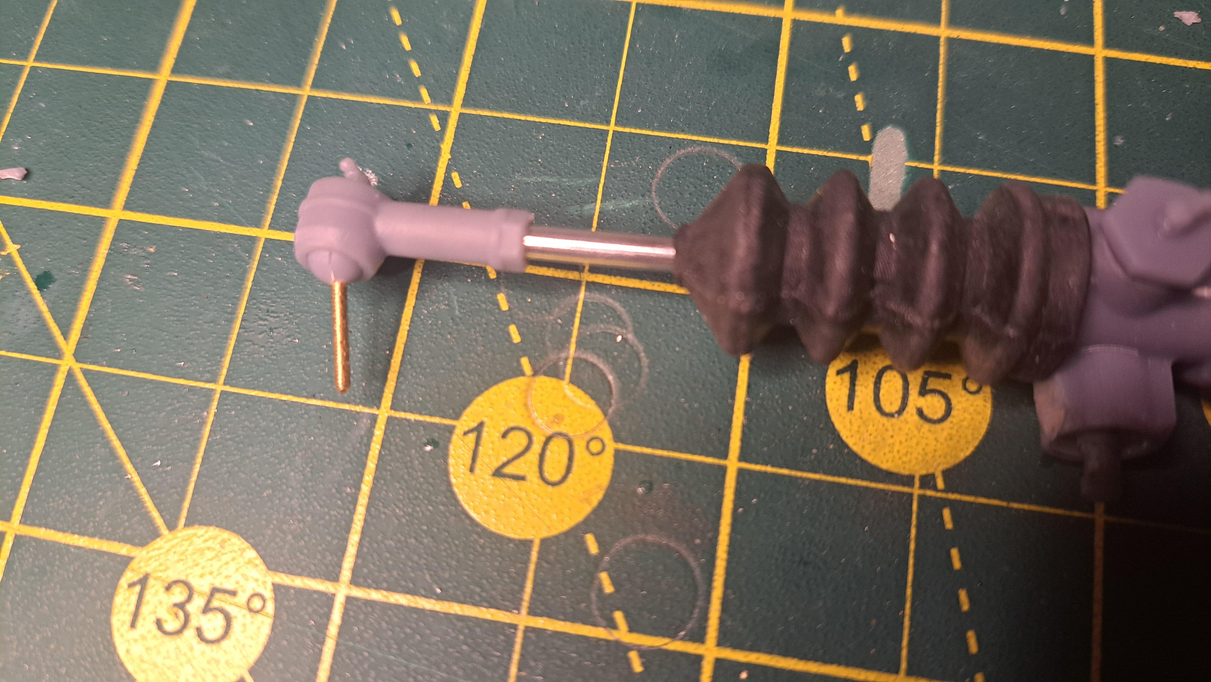
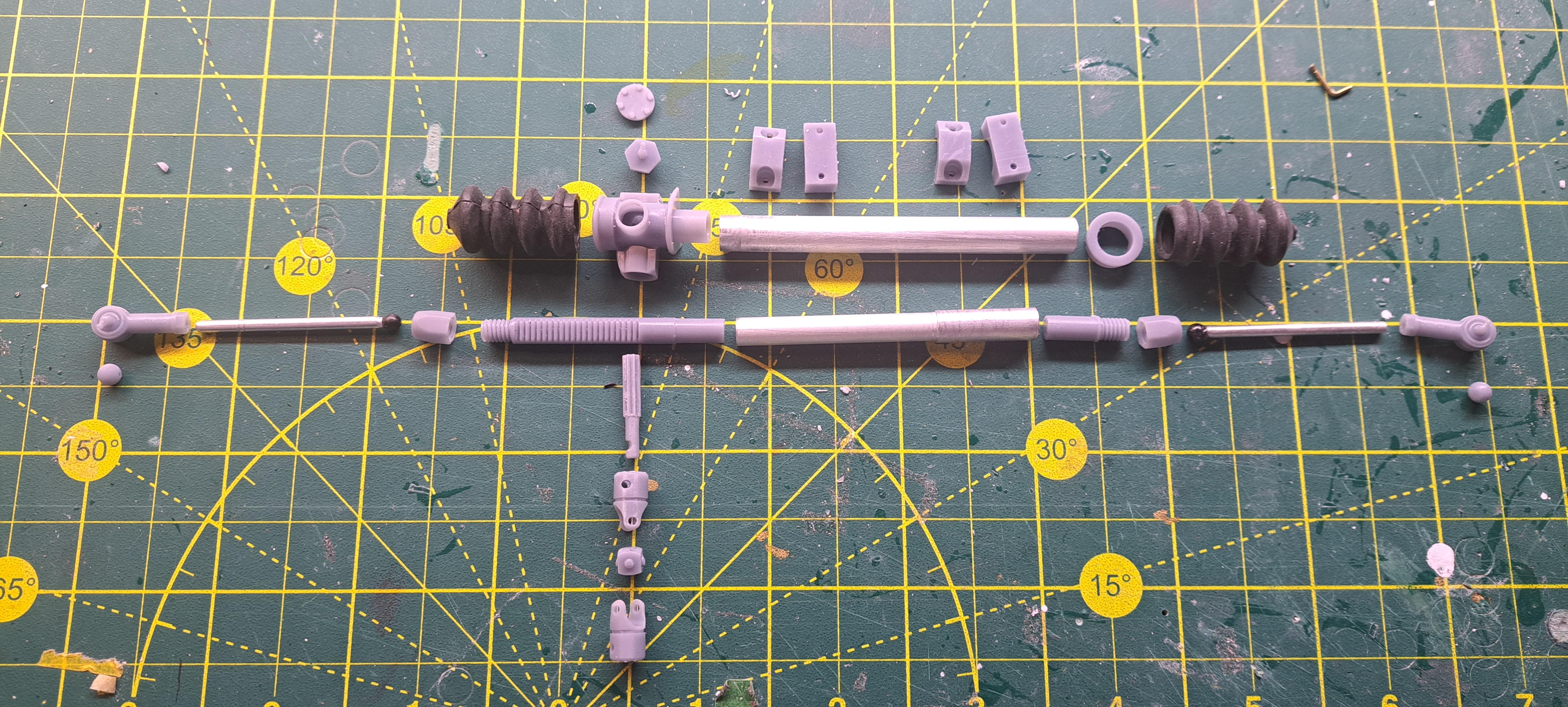
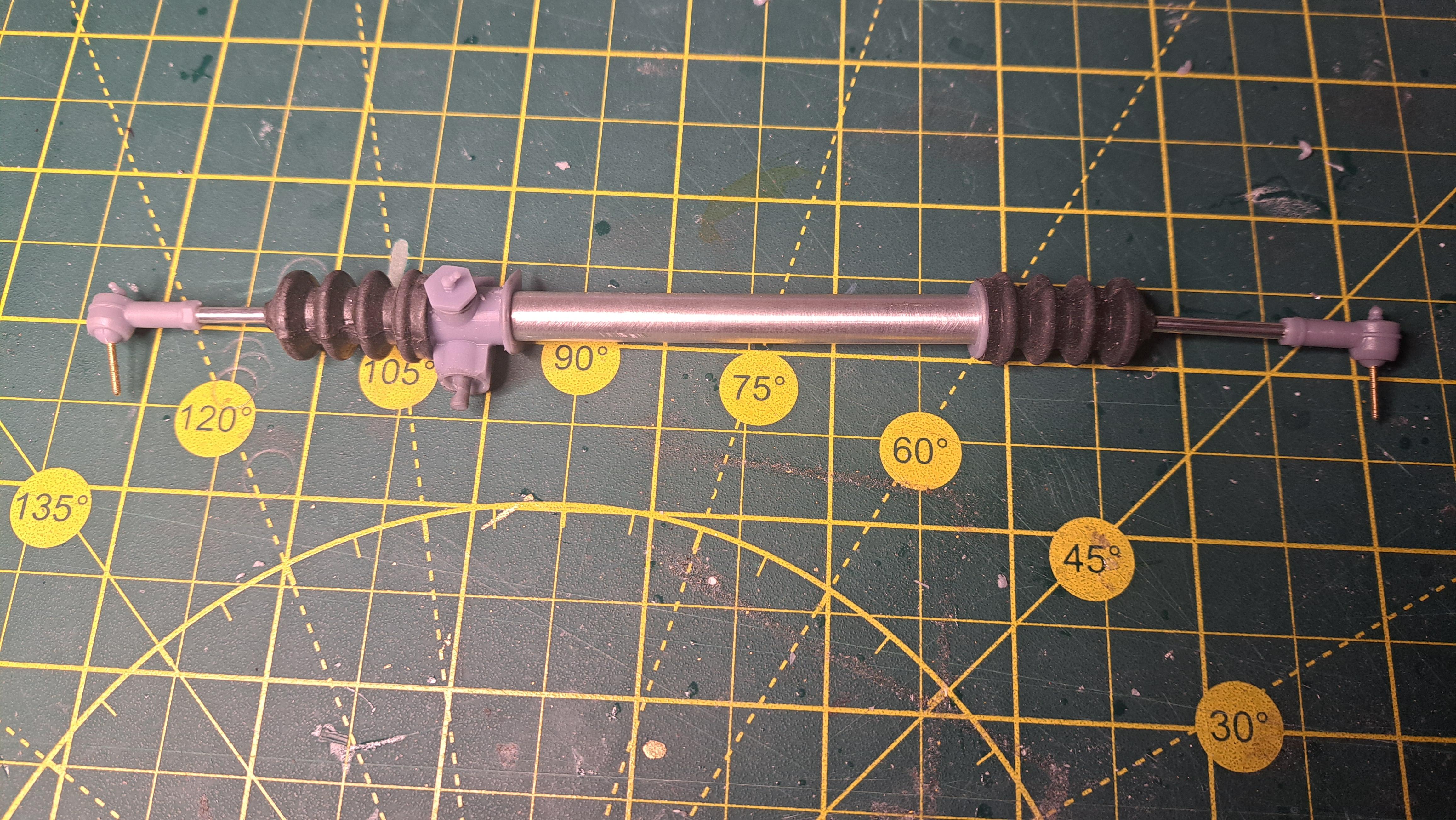
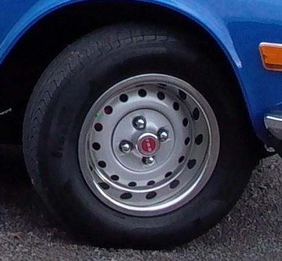
I've been doing some printing test these past few days. I have a working rack and pinion with working rod ends. I still need to refine it here and there but it's close. And I've ordered a miniature steel universal joint (5$ on Temu) to replace the printed ones as it will probably be a weak point in the steering mecanism. All components in the rack and pinion And assembled Working rod end with rubber booth (the boot comes from an RC boat I think) I also printed a complete wheel assembly, I am very pleased with the result. I tested my magnet idea to hold the wheel to the rotor and it works very well. It will be a breeze to remove the wheels to show the suspension. All components in 1 wheel And assembled And the real one
-
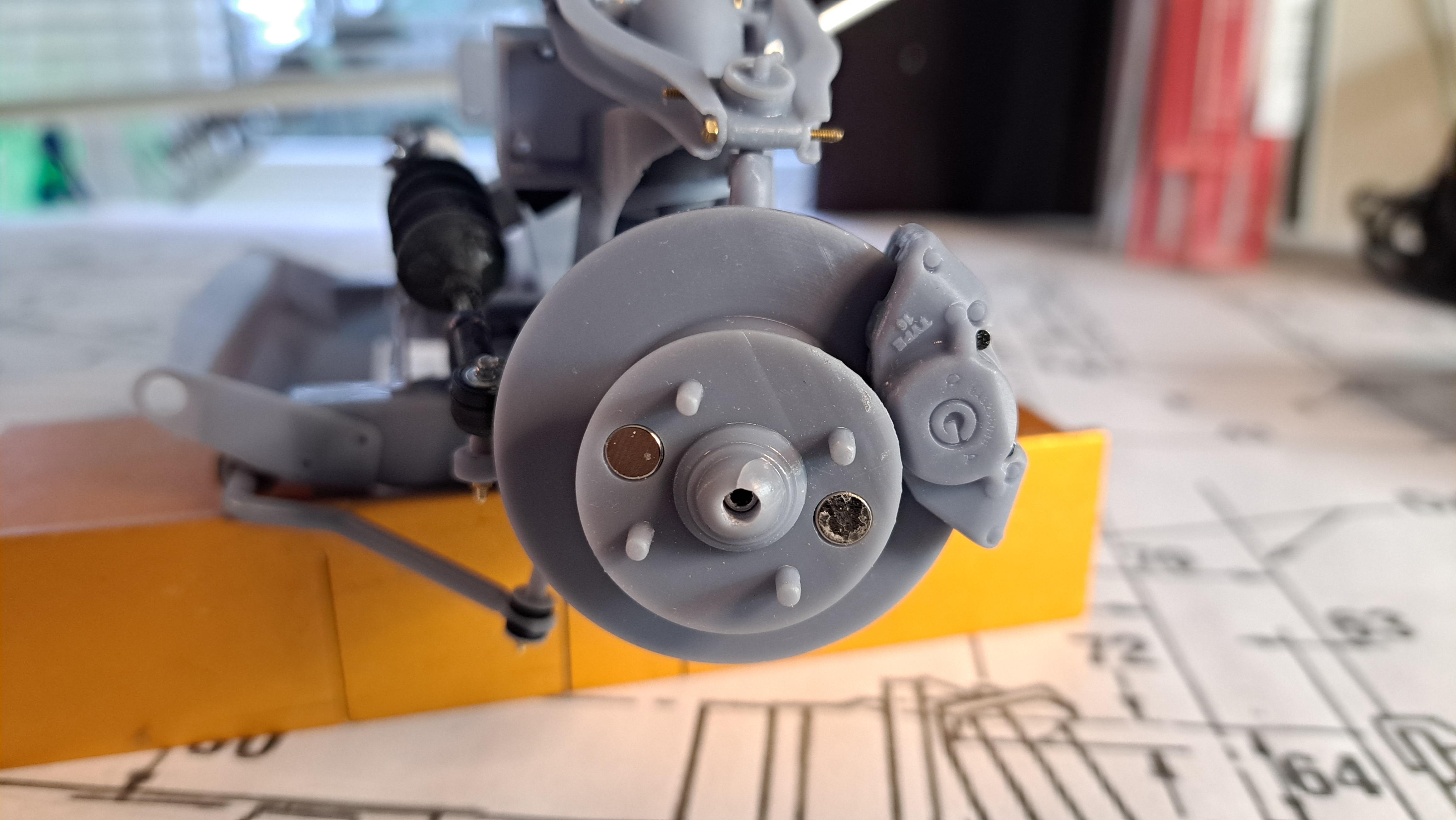
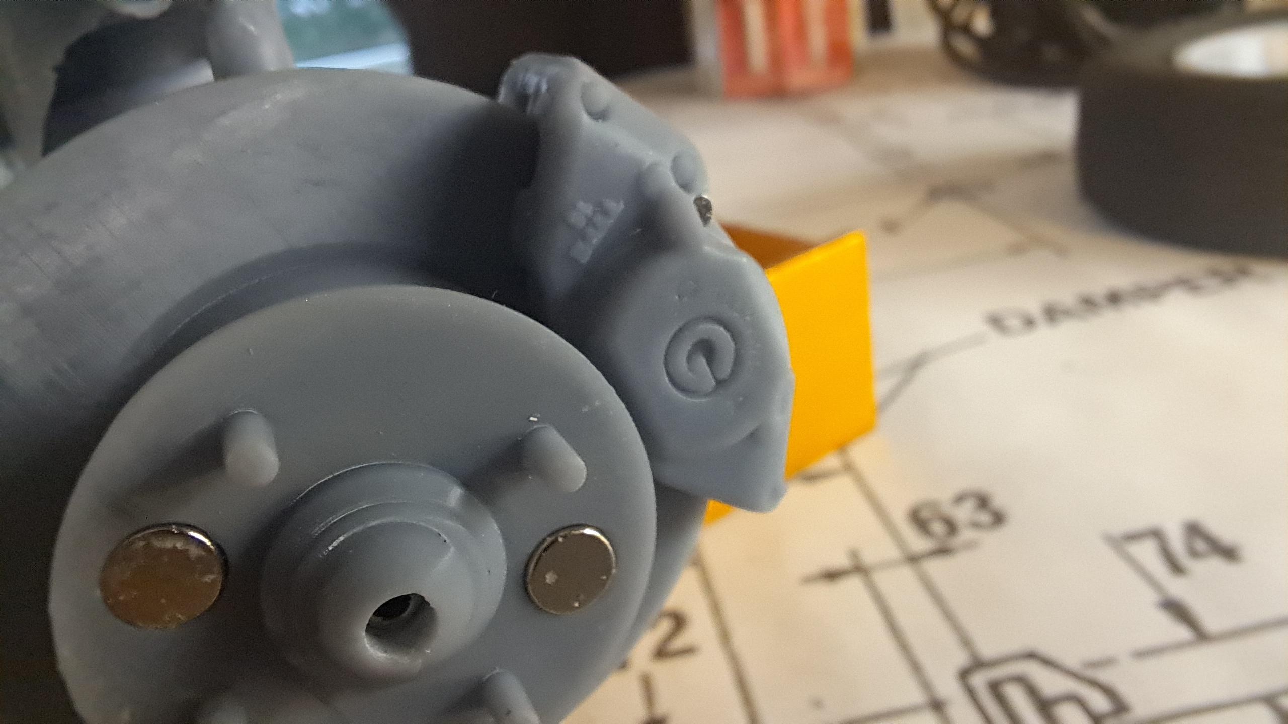
Finished the wheels today and the front axel. I wanted to find an easy way to remove the wheels. My first idea was to do like i did with the Hydra, to use the center cap as a screw. But then I thought of another idea, magnets. I'll inbed 2 magnets in the each hubs and 2 in each wheels. I'll test it before going final with it. The finished wheel Vs the real one The magnet idea
-
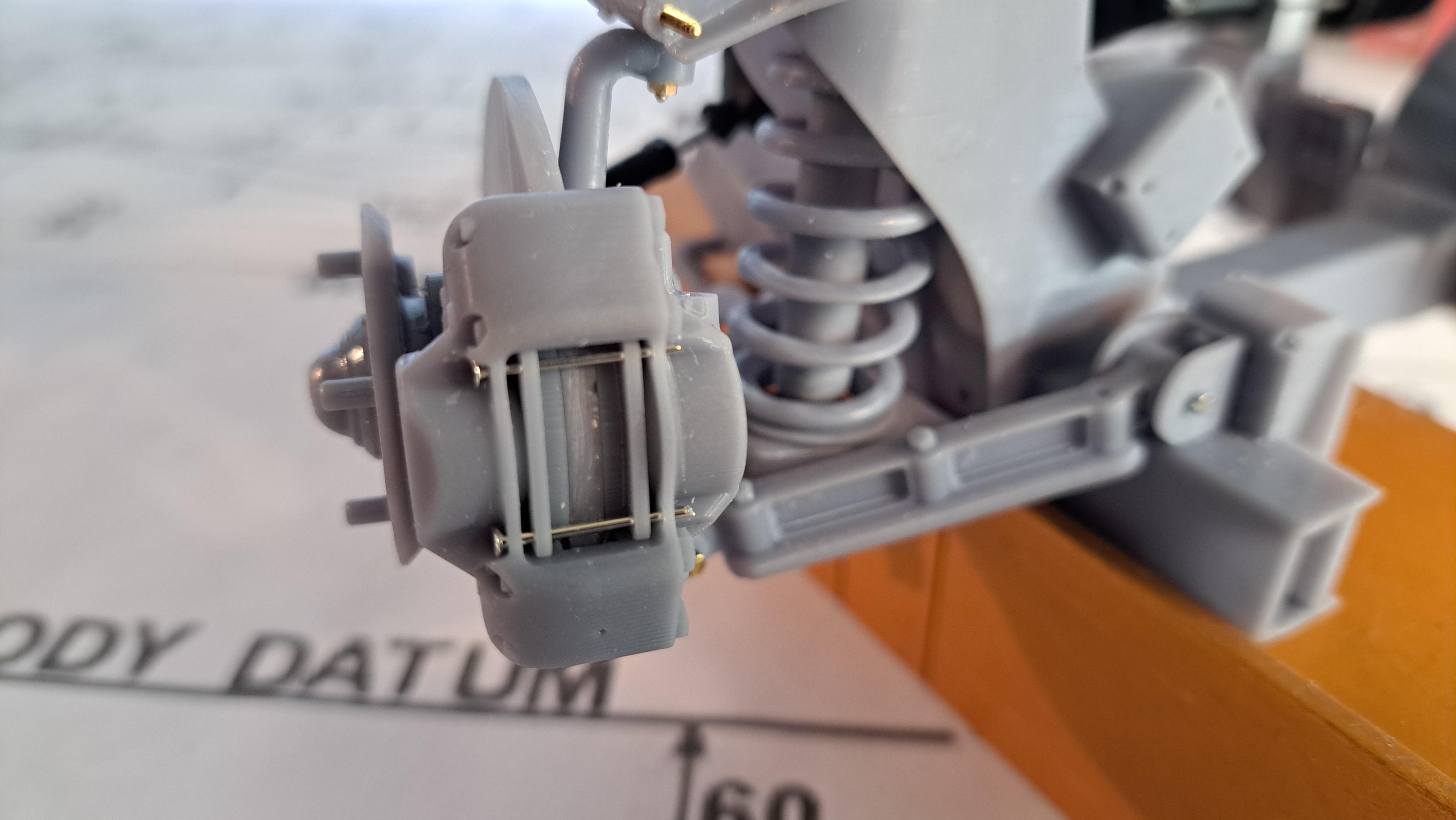
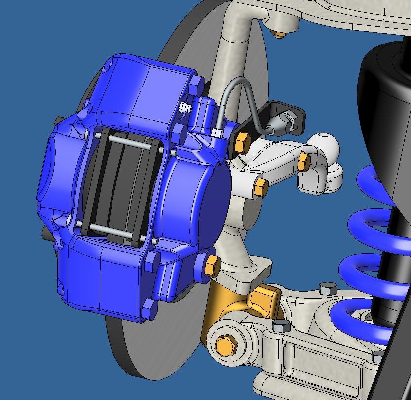
So the calipers are finished. I added the rigid fluid line and the brake pads. I also started the rack and pinion. I'm aiming at a working rack but I've never modeled one before. It will be interesting to see if I can pull it off.

.jpg.61a967286b1506d112811b562e350eb7.jpg)


.jpg.0dbd5678f1b827f81318985be7e03cec.jpg)