François
-
Posts
489 -
Joined
-
Last visited
Content Type
Profiles
Forums
Events
Gallery
Everything posted by François
-

Marvel's Hydra coupe 1/12 scale full scratch build
François replied to François's topic in WIP: Model Cars
I printed the seats, they will be covered with the same leather I used for the rear seat and door panels. If you look closely at the print, you will see a hole on the lower portion of the seat plus some striations (lines) on certain surfaces. They should not be there. After some research, it appears my LCD screen is shot and needs to be replaced. Apparently, an LCD screen on a printer is a consumable with a life span anywhere from a few months to a few years depending on use. I was wondering with my prints where not as nice as before. Thankfully, I only need to reprint the tool box covers since I now understand why they look like they do. Live and learn...
-
Marvel's Hydra coupe 1/12 scale full scratch build
François replied to François's topic in WIP: Model Cars
This is the latest test, and hopefully the last, before I resume clear coating the parts. Here's what I did. Starting with my test piece that had a coat of finish paint and 3 coats of clear, the clear was wet sanded and received another coat of clear. This last coat was sanded it with the 3000 pad and wet sanded with the 5000 pad. I then buffed the left side using my 3M buffing compound, my 3M hand glace and finished with a polymere wax. These 3 last steps were done using a cotton wheel on my dremel at the lowest speed. The right side is as it was after sanding. The result is quite nice and the waxed surface is slippery as should be. So here's how I will proceed for the rest. All parts that had received 3 coats of clear have been sanded with the 3000 and 5000 pads. They will receive a new wet coat of clear and once cured, will be lightly sanded, buffed, glazed and waxed. As for the parts not yet cleared, they will get 3 coats of clear followed by the steps described above. I will pay more attention to the cleaning and dust control.
-
Marvel's Hydra coupe 1/12 scale full scratch build
François replied to François's topic in WIP: Model Cars
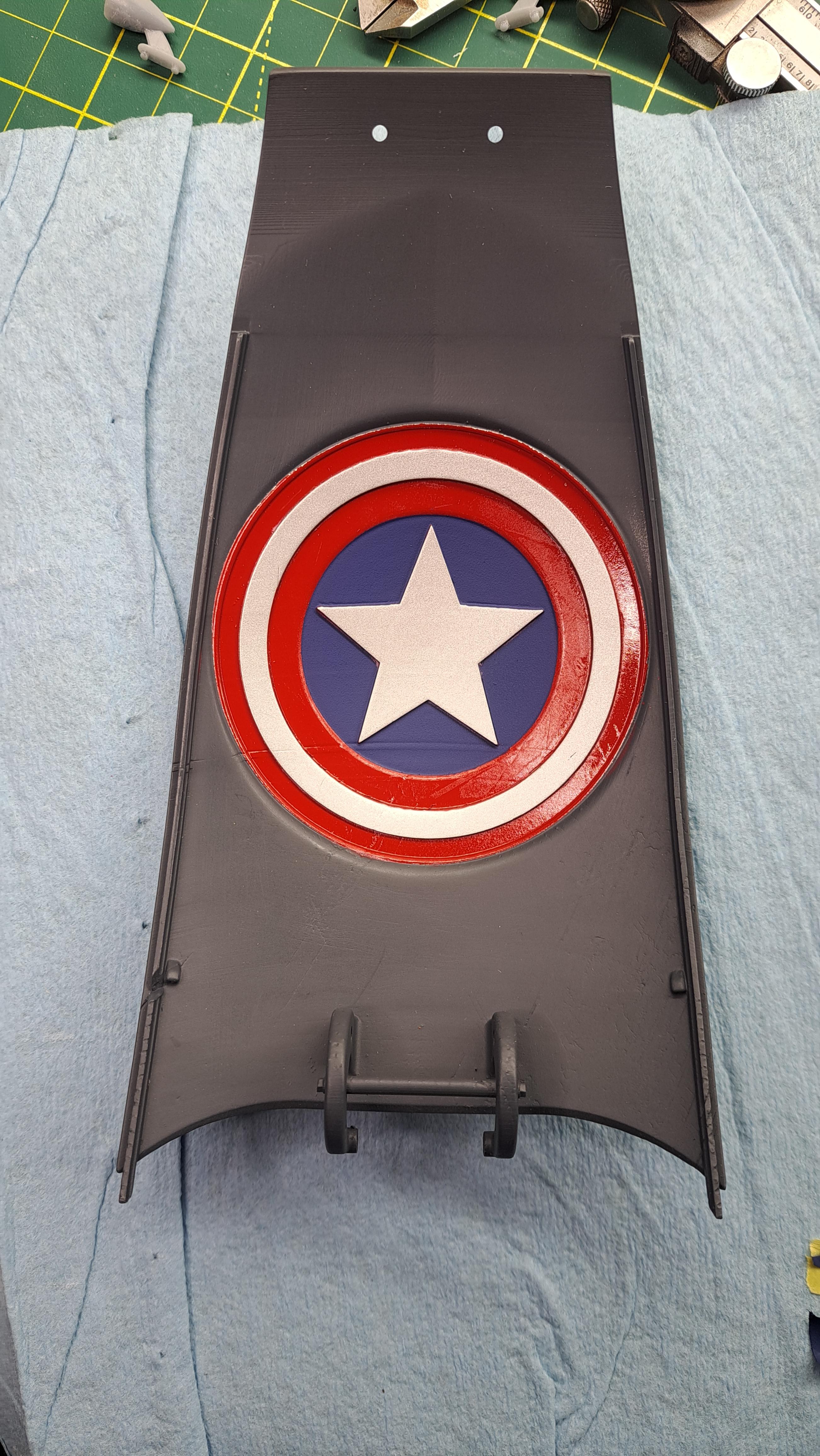
I'm on a fairly steep learning curve with the paint and clear process. I cleared all parts except the fenders, the rear trunk lid and the body. The result is ok, no more. I need to better control the dust (I got a tack cloth for this) and to better degrease the parts. After testing on a spare part, I decided to sand the cleared parts with a 3000 grit tamiya sponge pad first and then with a 5000 grit polishing pad (dry and wet). I will then re-apply a wet coat of clear. Once this coat has cured 48 hrs, I will see if another 5000 wet polish is needed or if I can just wax it as is. It's a very slow process. Tamiya 3000 pad 5000 polishing pad Second clear test on spare part I finished the of day by painting the shield on the inside of the trunk lid. Still need to do a few touch-up and to apply the clear but I'm happy with the result.
-
Marvel's Hydra coupe 1/12 scale full scratch build
François replied to François's topic in WIP: Model Cars
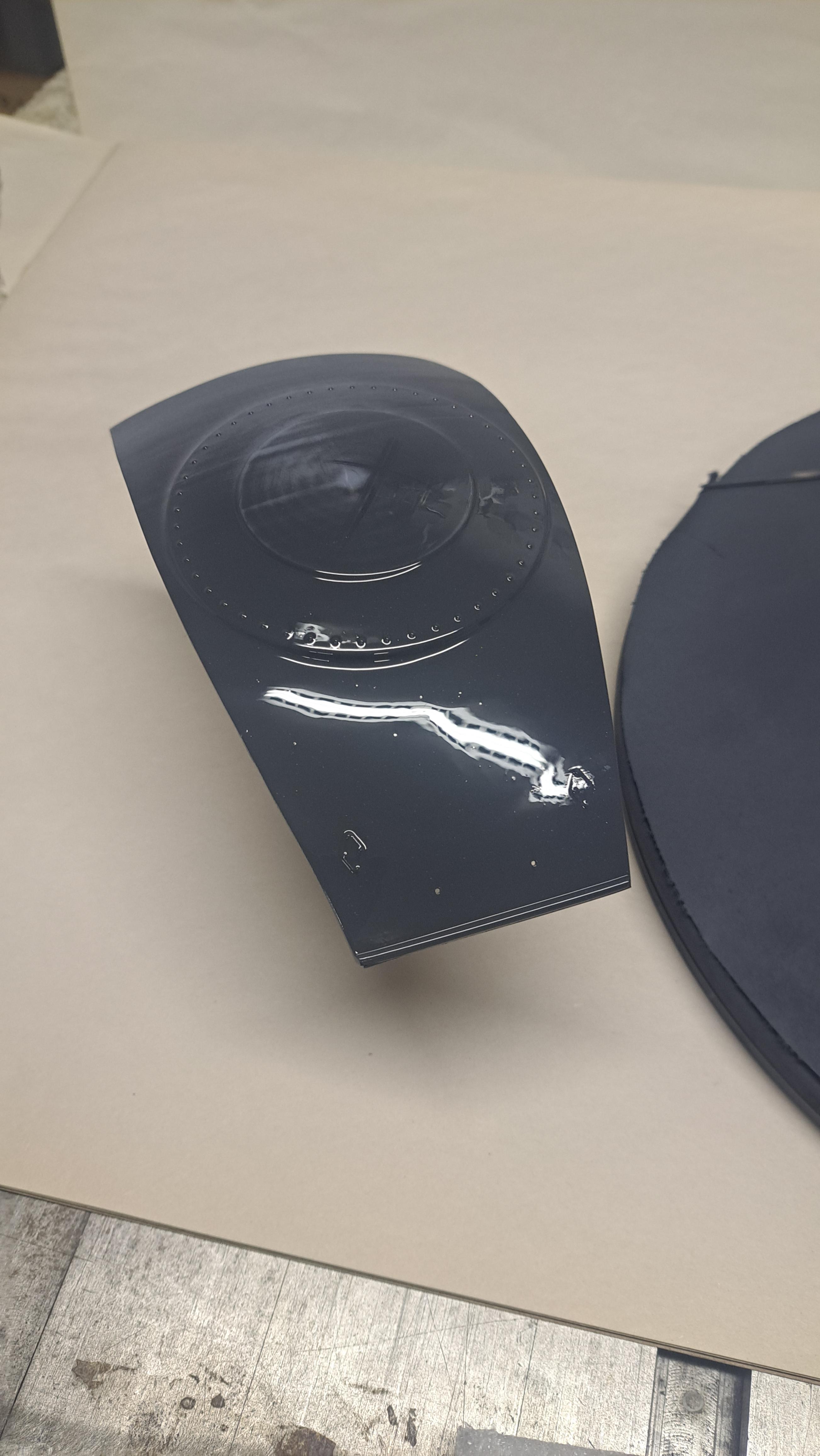
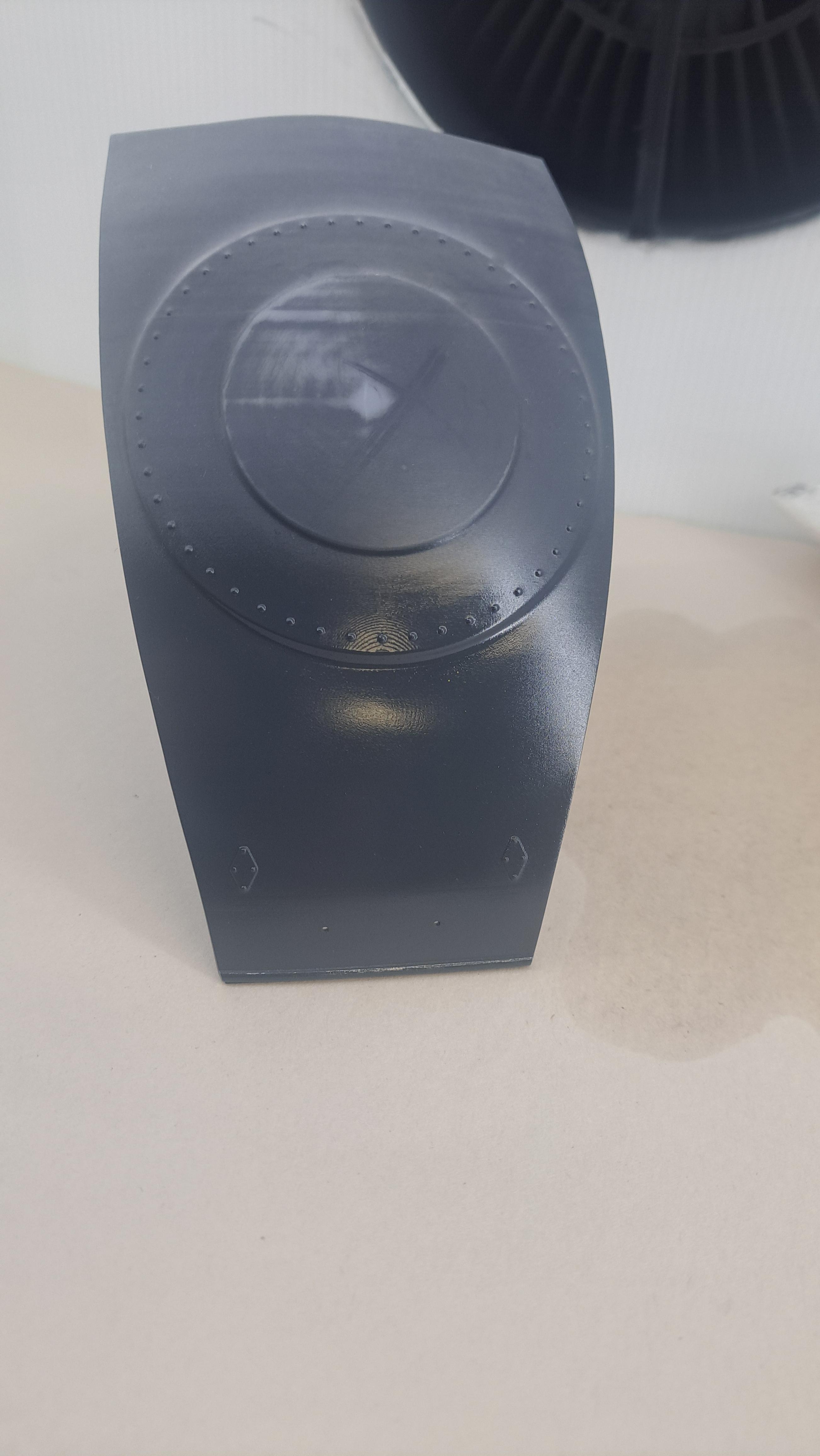
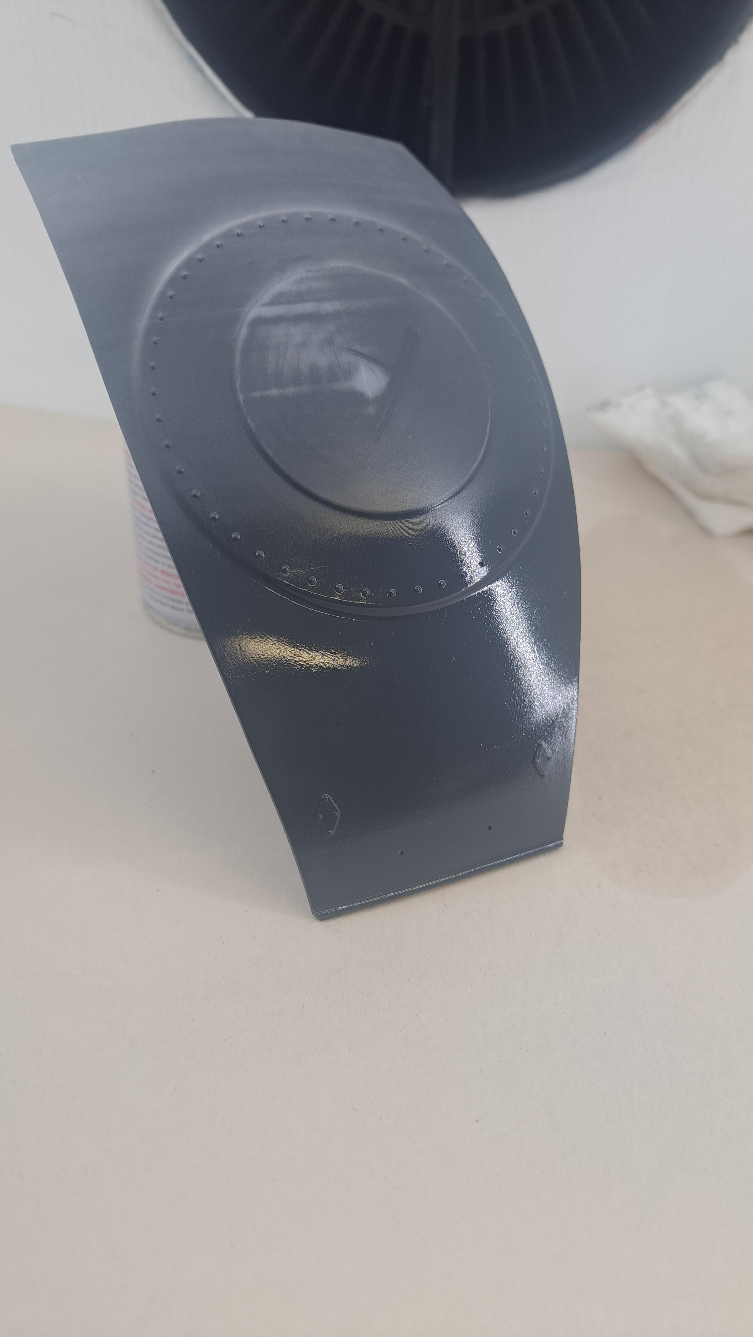
Ok so I painted all the body parts with Tamiya's german gray spray paint. As mentionned before, tamiya spray paints are no longer available in Canada but I was lucky enough to find 5 cans of the same color that was close to the gray I wanted. It took 4.5 cans to spray all the body parts (including the previously painted blower, wheels and front light brackets) so not much room for a error there (absolutely no pressure !!). Next step is to clear coat the parts with Tamiya's LP-9 clear lacquer diluted 50/50 with Tamiya's lacquer thinner (the orange capped bottle, apparently it has a retarder in it). But before clear coating the actual parts, I did a test on a extra trunk lid. I laid 3 light coats at 5 minute intervals followed by a last wet coat. Once it's cured (no clue as to curing time but I figure an overnight cure should be good), I'll do some buffing tests with and without wet sanding. Hopefully, I won't need to much wet sanding. After 2nd light coat (forgot the take a picture of the first) After 3nd light coat And after wet coat
-
Marvel's Hydra coupe 1/12 scale full scratch build
François replied to François's topic in WIP: Model Cars
Did the leather on the door's inside panels. It's not perfect but I should be able to get it close with a bit of tweaking here and there and a bit of shoe polish.
-
Marvel's Hydra coupe 1/12 scale full scratch build
François replied to François's topic in WIP: Model Cars
All body parts have been primed, wet sanded and primed again. They are now ready for final color.
-
Marvel's Hydra coupe 1/12 scale full scratch build
François replied to François's topic in WIP: Model Cars
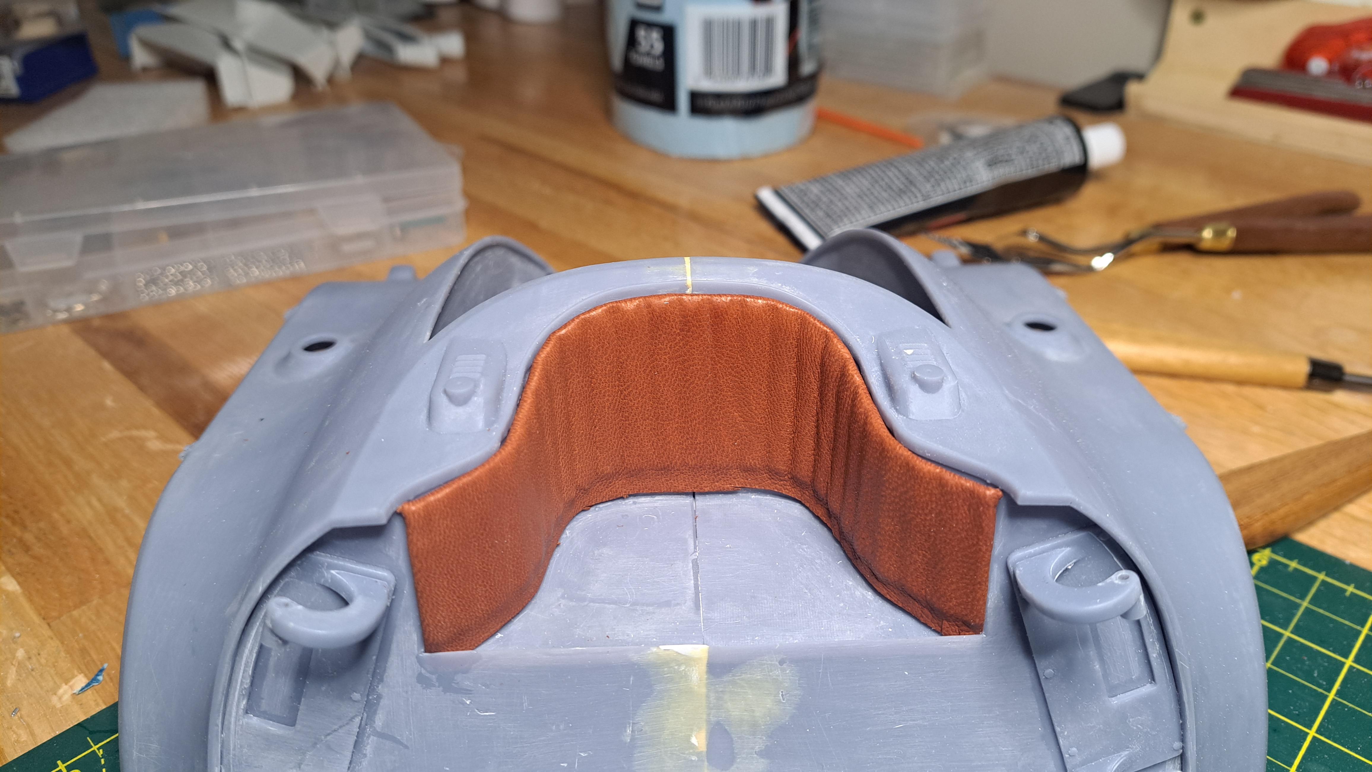
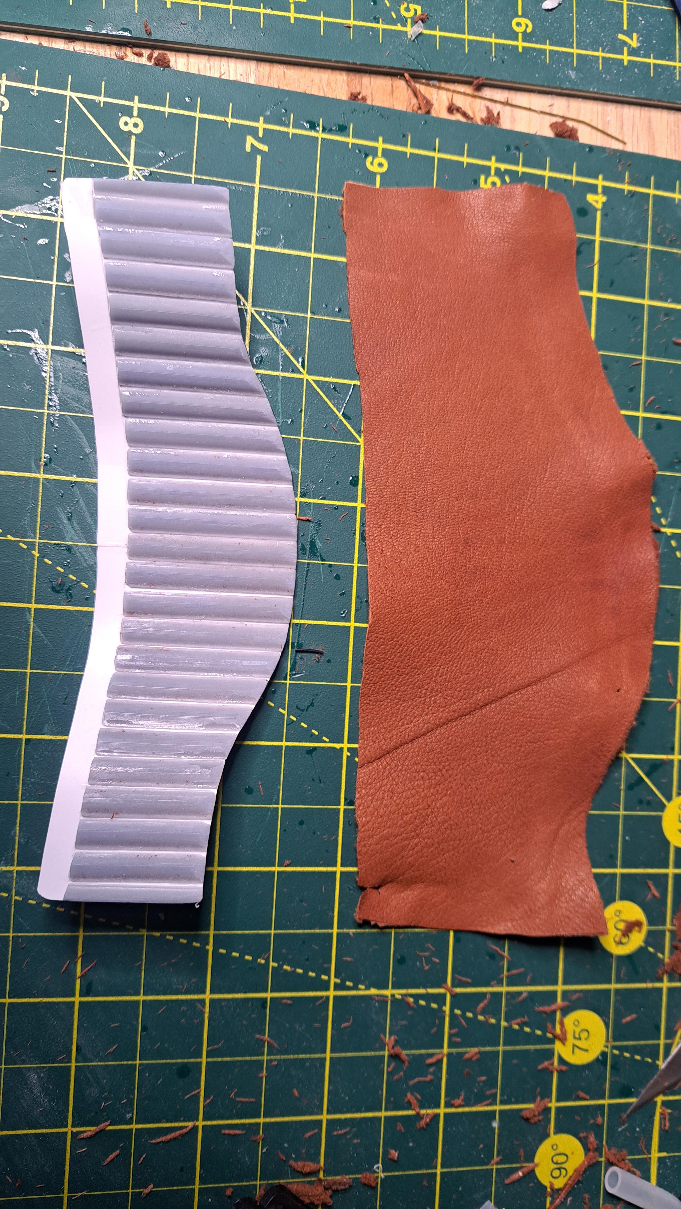
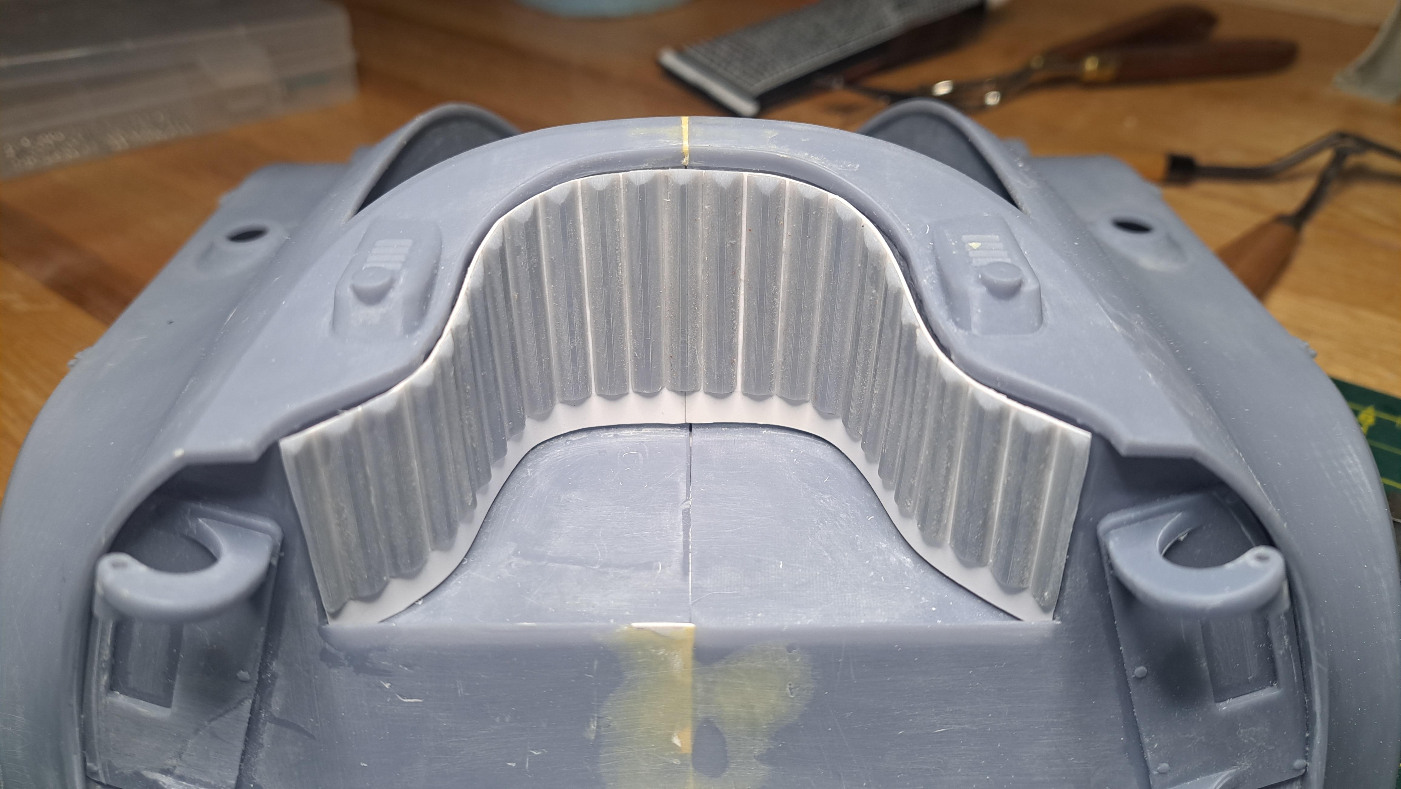
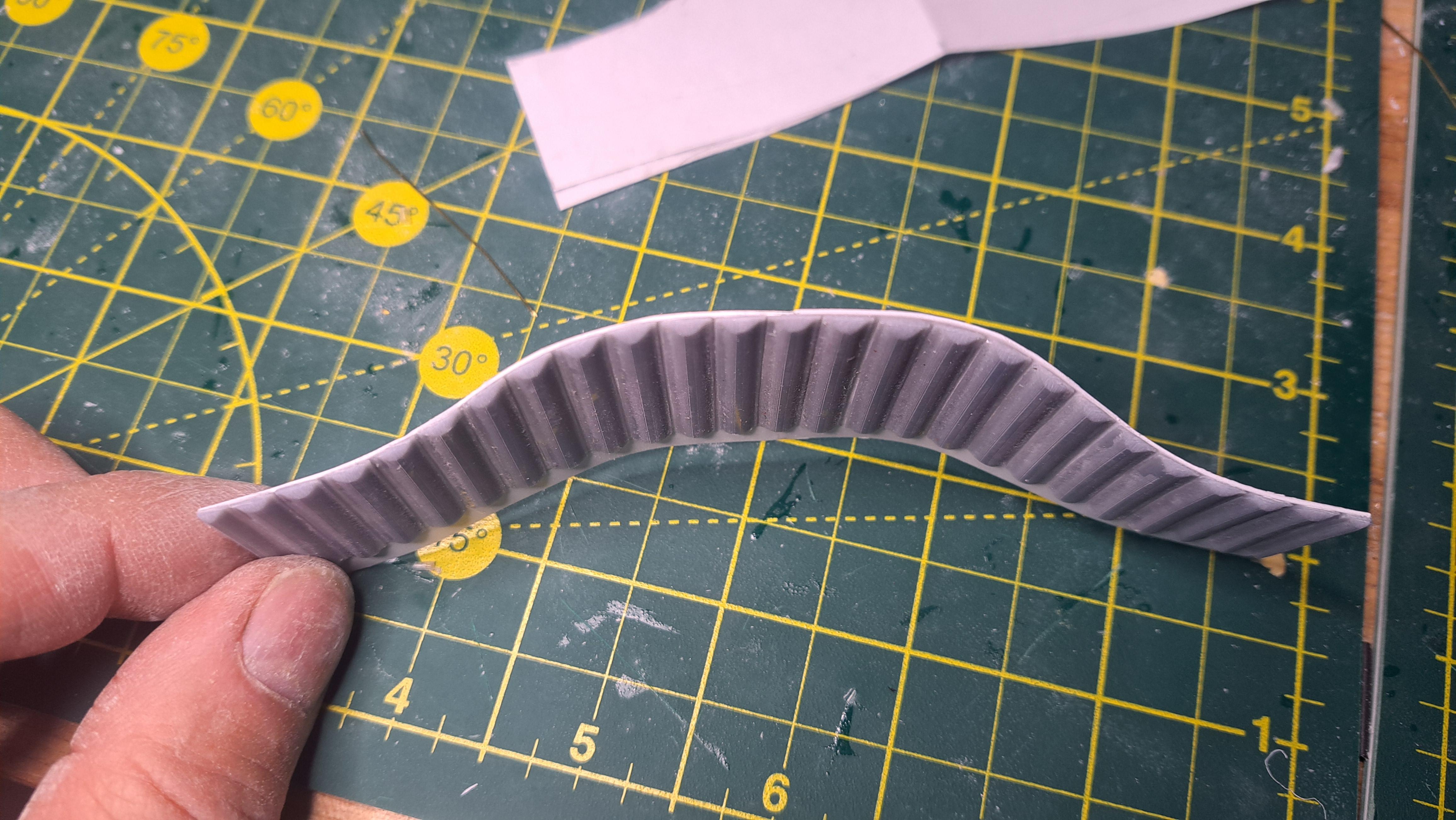
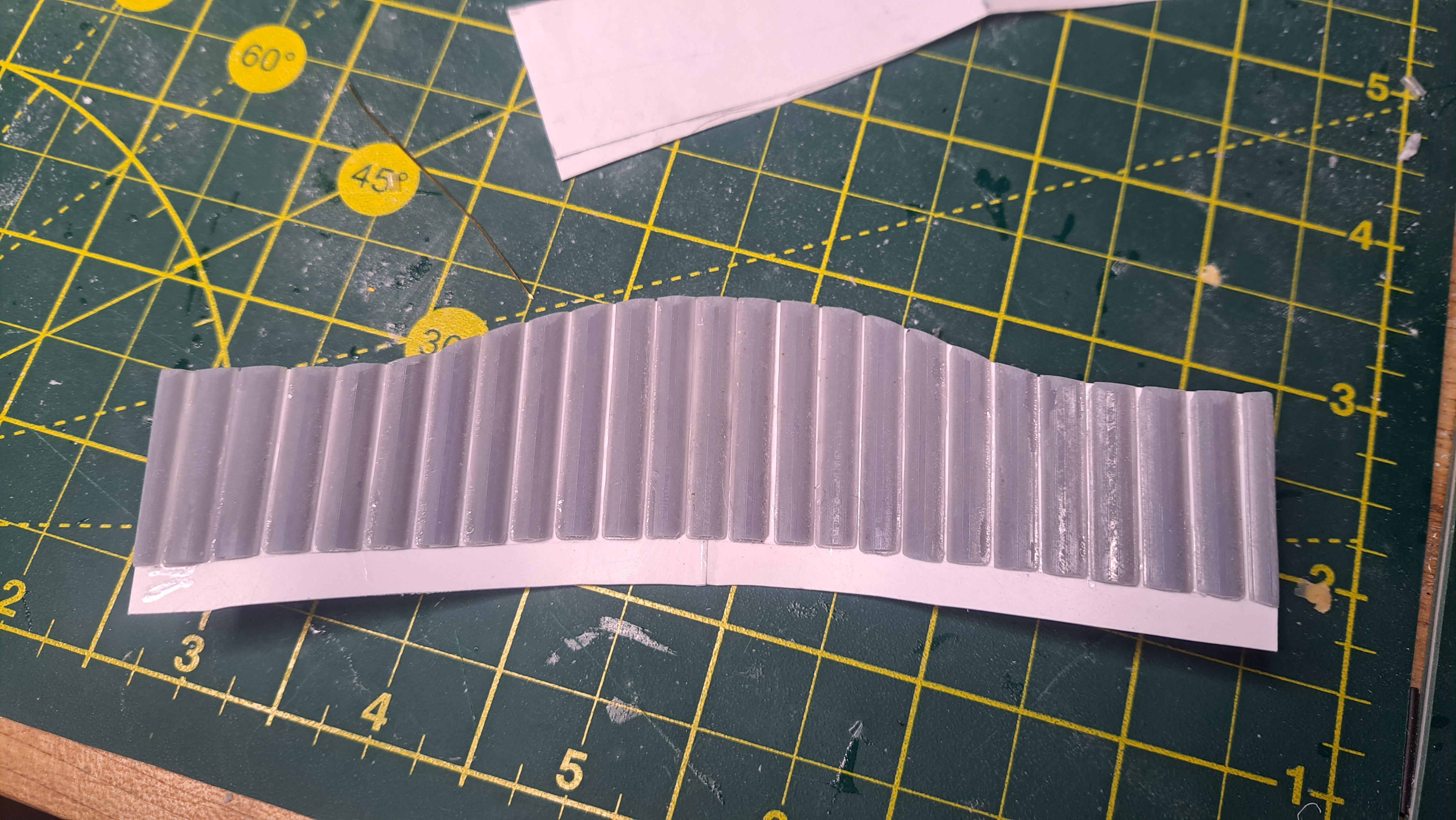
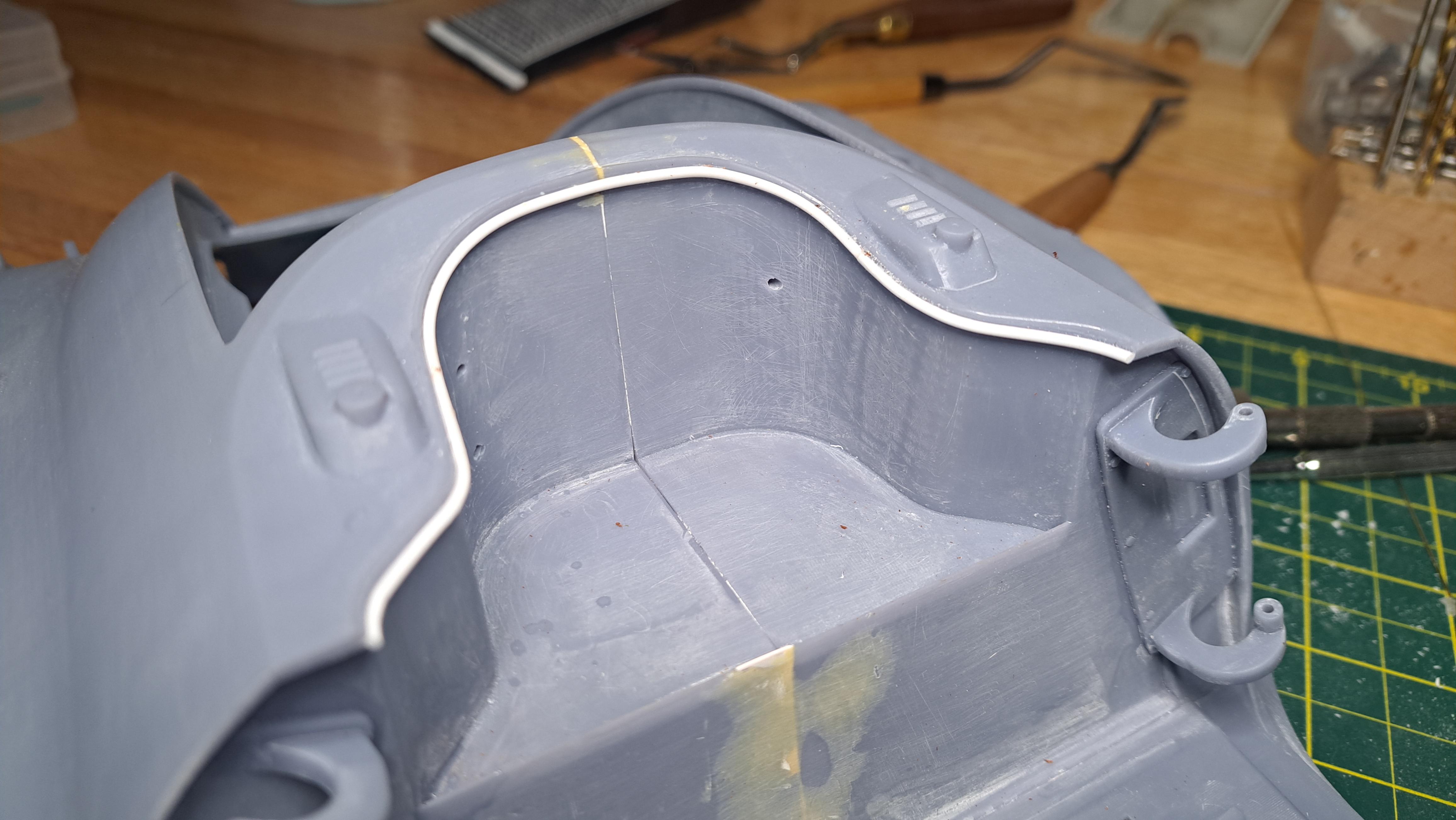
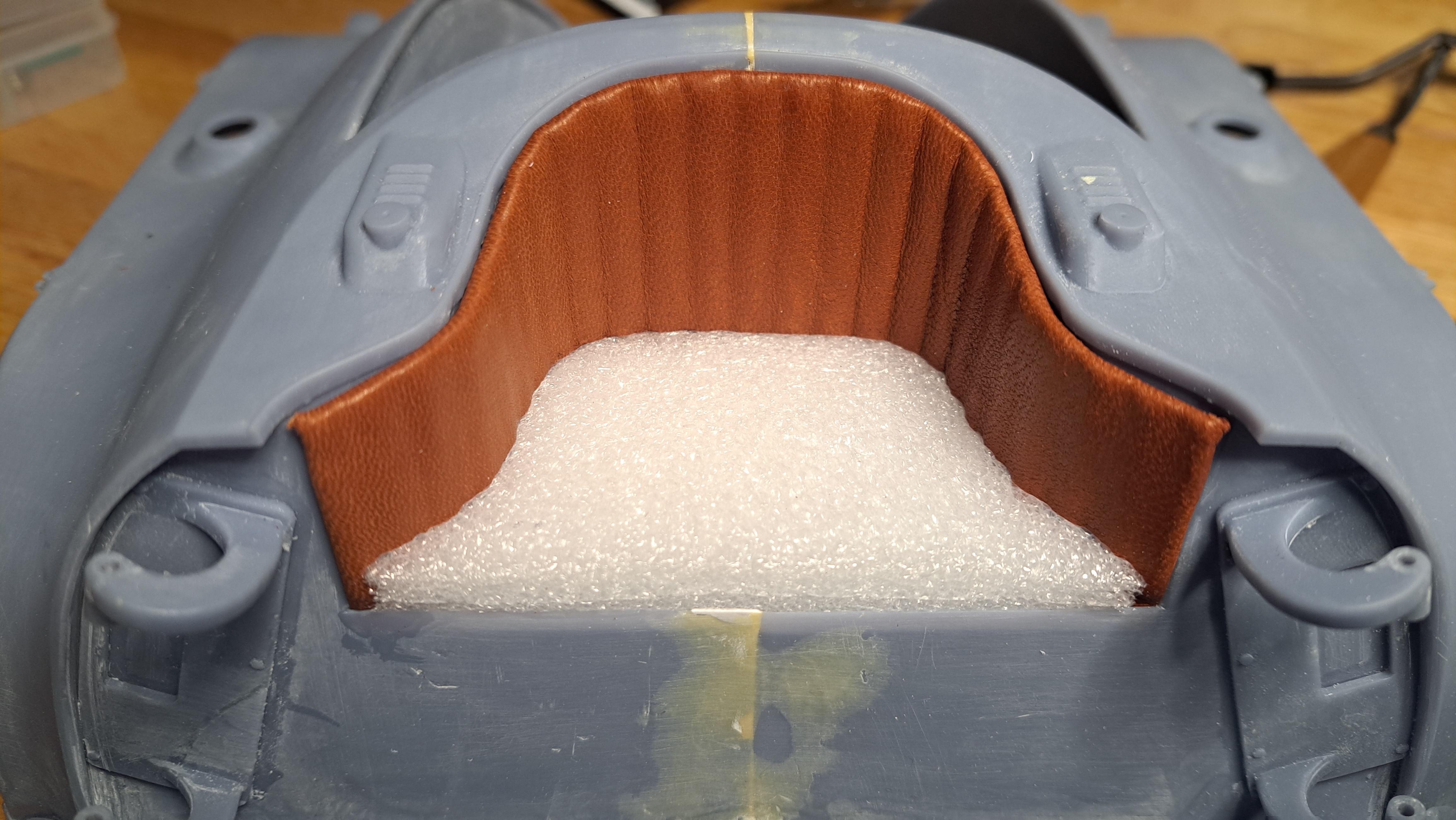
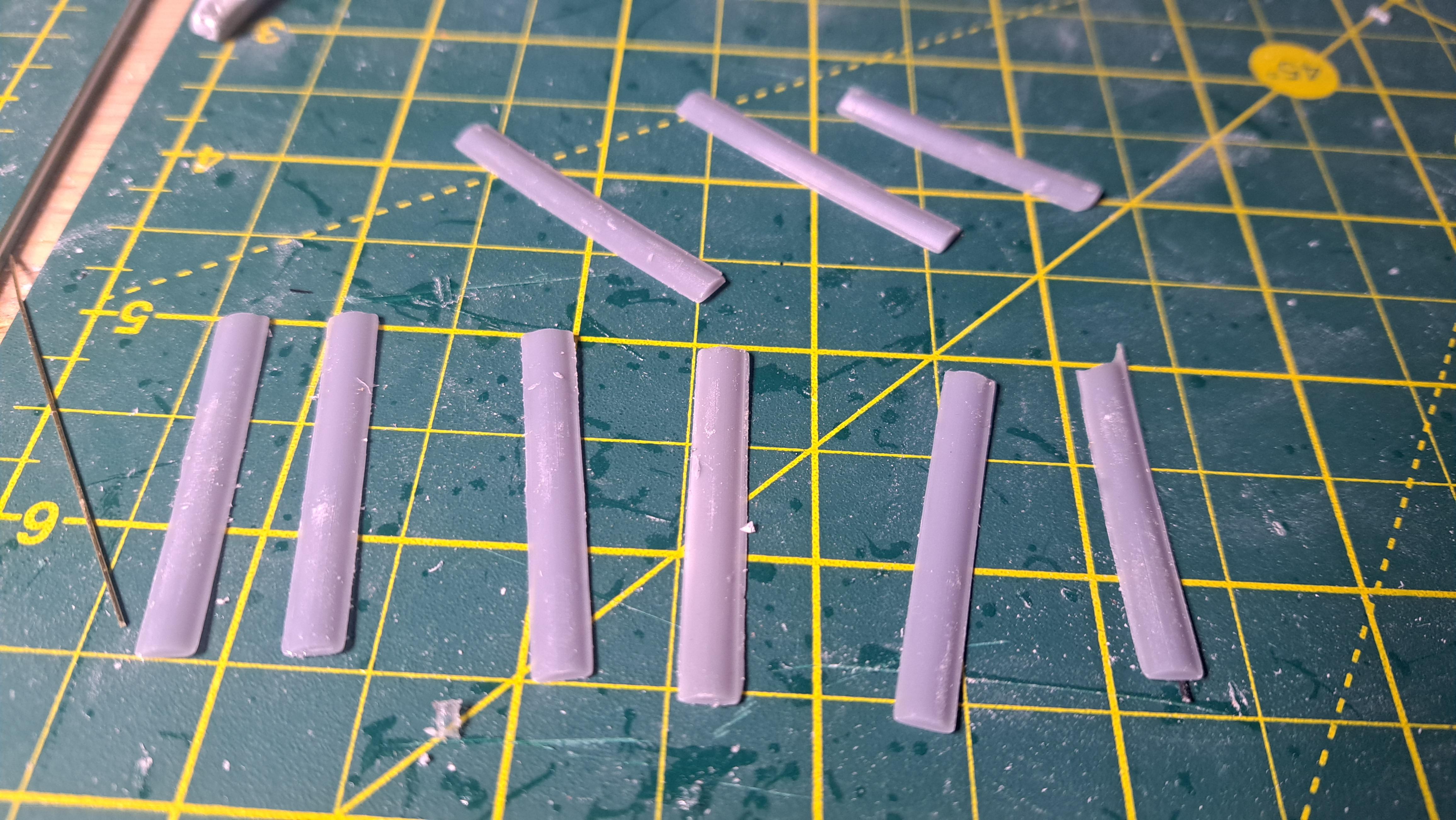
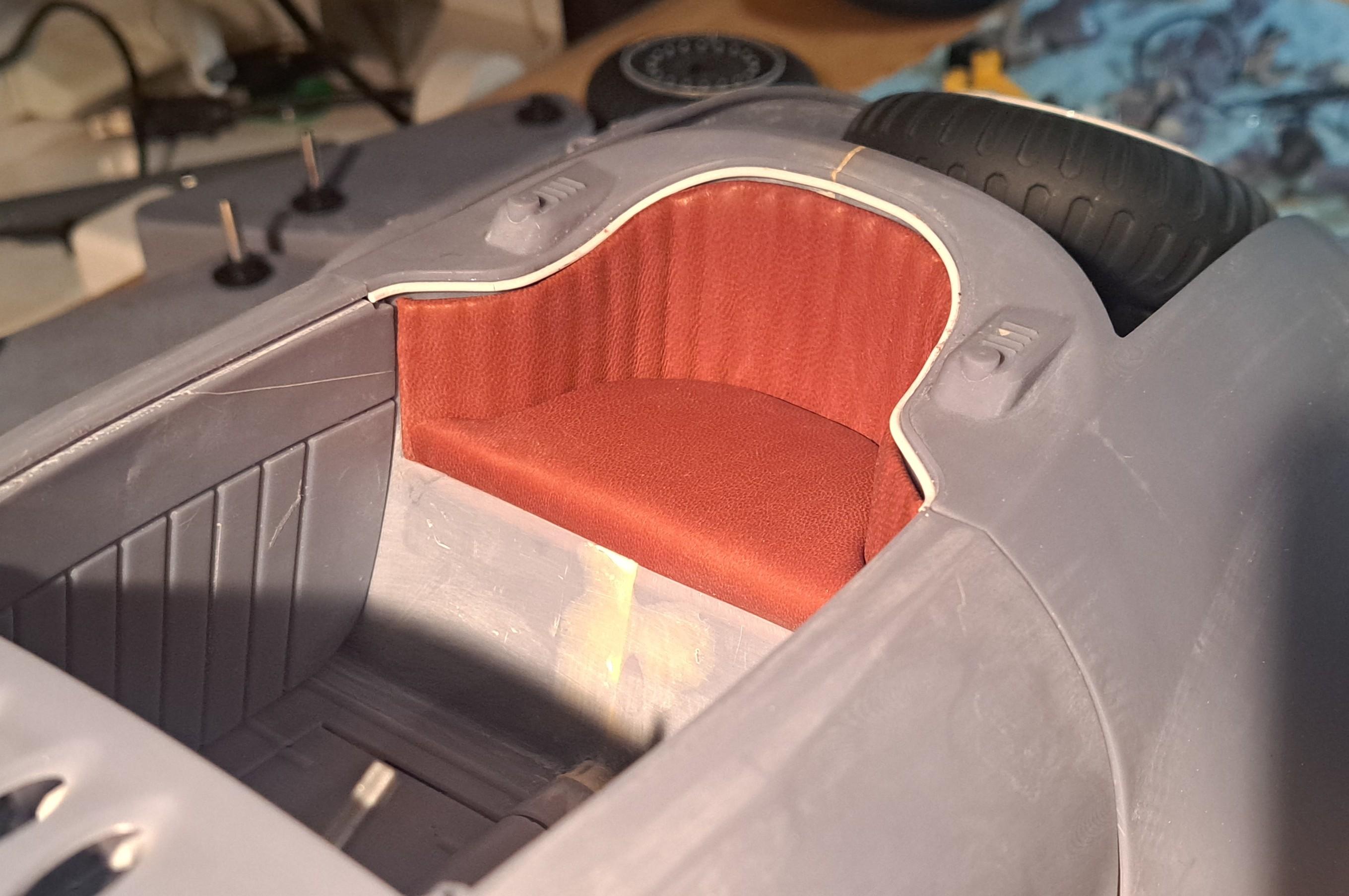
I did the rear seat today. Here's how it was done. I first made a paper template of the back rest. Which was then transfered to a .015" thick plasticard I 3d printed a bunch of domed strip to create the back cushion shape Which were glued to the plasticard Next came the leather And once glued I then cut a piece of white foam for the seat cushion And covered it with leather But I didn't like the gap between the back cushion and the body so glued a 1/16" dia styrene rod to create a lip that will hide the gap. The rod will be painted the same color as the bodywork. I'm very happy with the result even though it's not final since I have to remove the seat for painting. And the last project for today was to make a new bigger spray booth. The hydra body didn't fit in the old one. At 28" wide x 14" deep, it will accomodate bigger parts.
-
Marvel's Hydra coupe 1/12 scale full scratch build
François replied to François's topic in WIP: Model Cars
With the rear wheel covers done, that concludes the body printing phase of this project. I think I'll do the rear seat before priming the body.
-
Marvel's Hydra coupe 1/12 scale full scratch build
François replied to François's topic in WIP: Model Cars
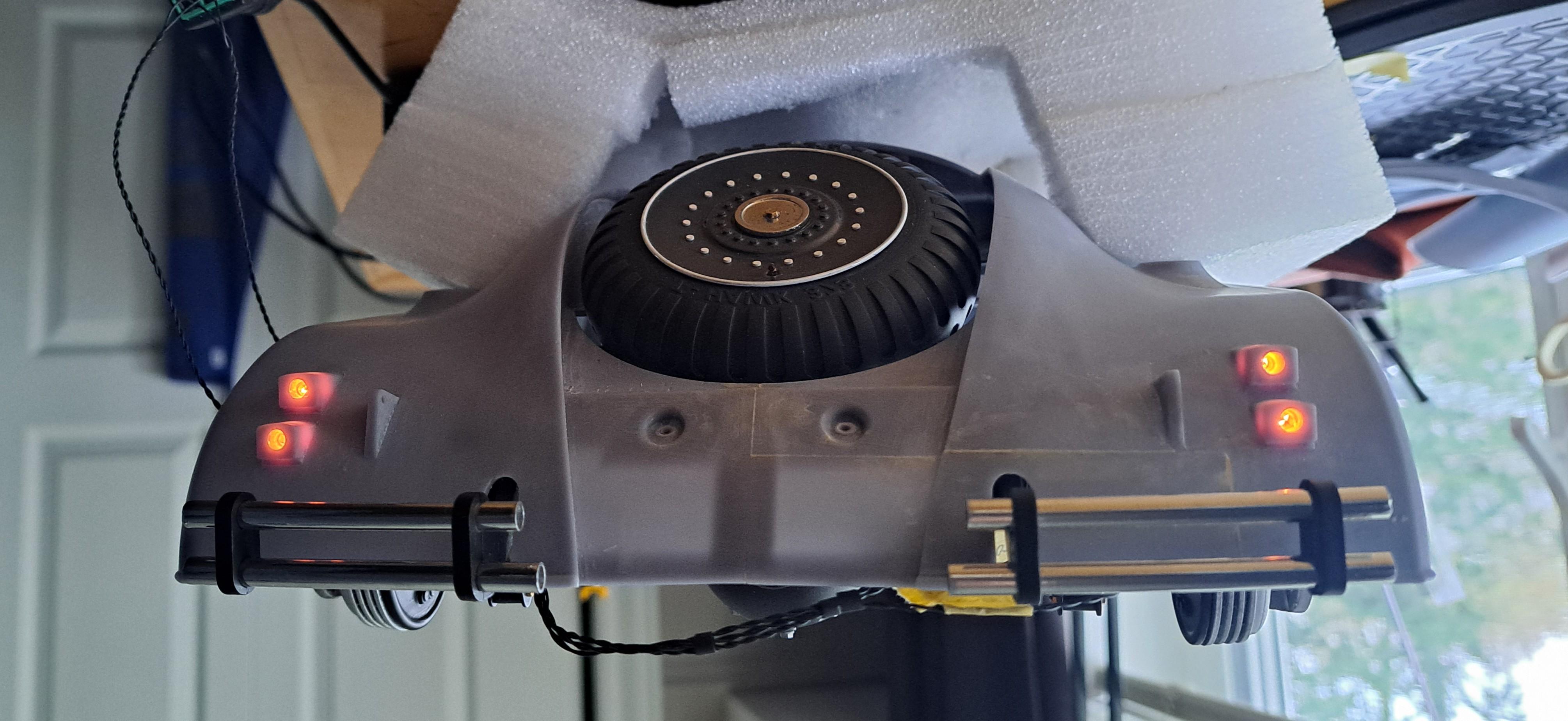
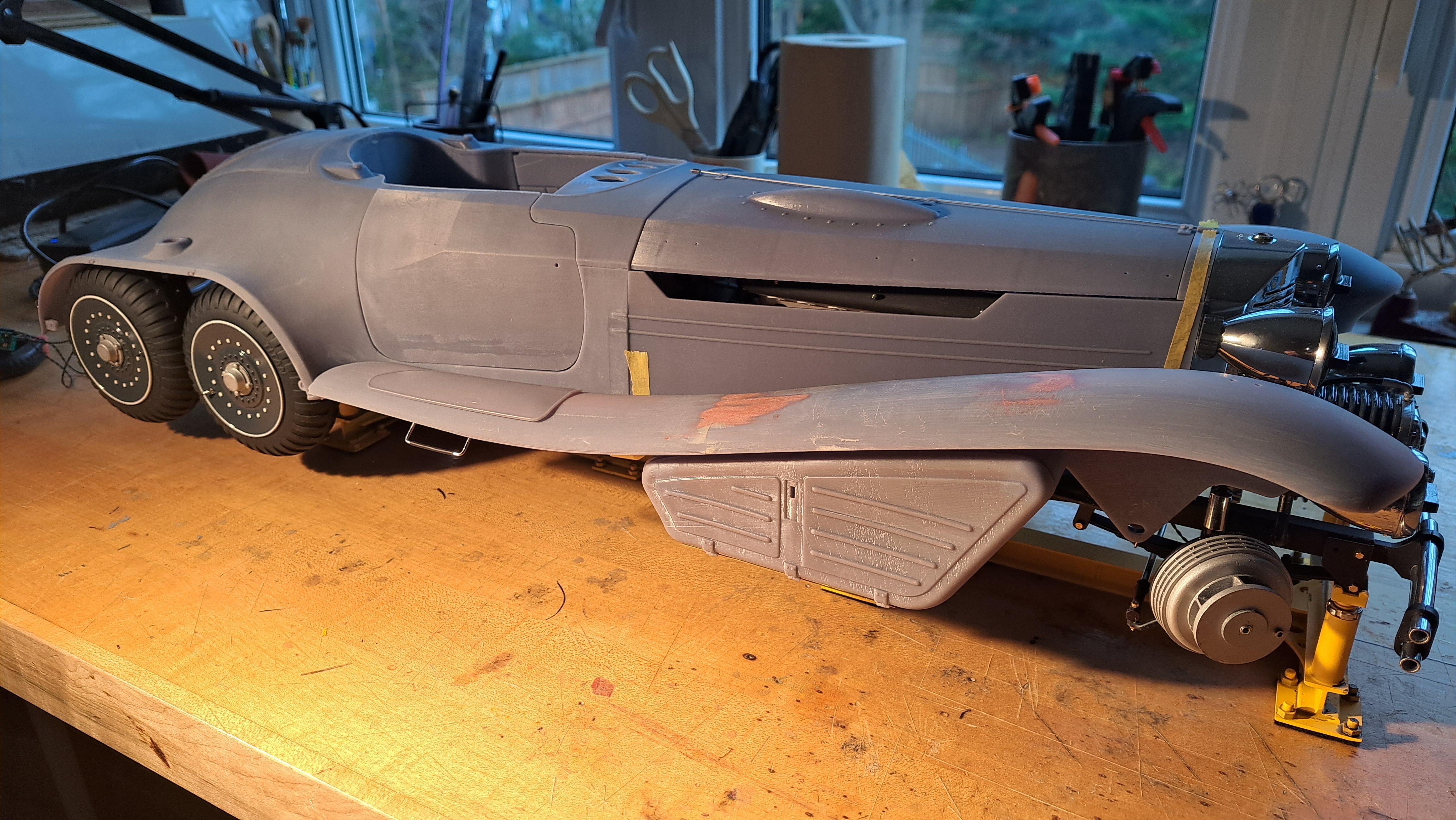
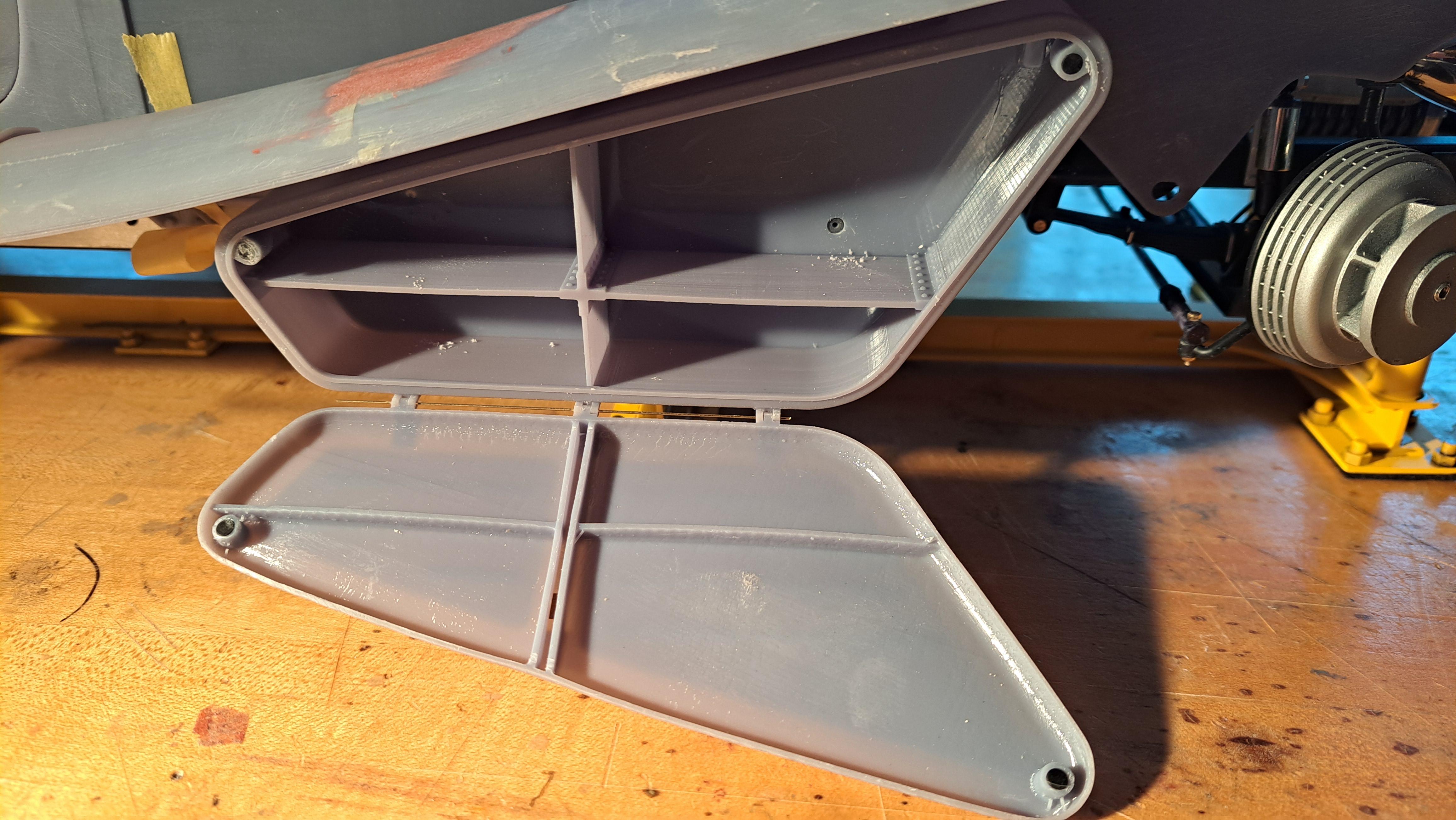
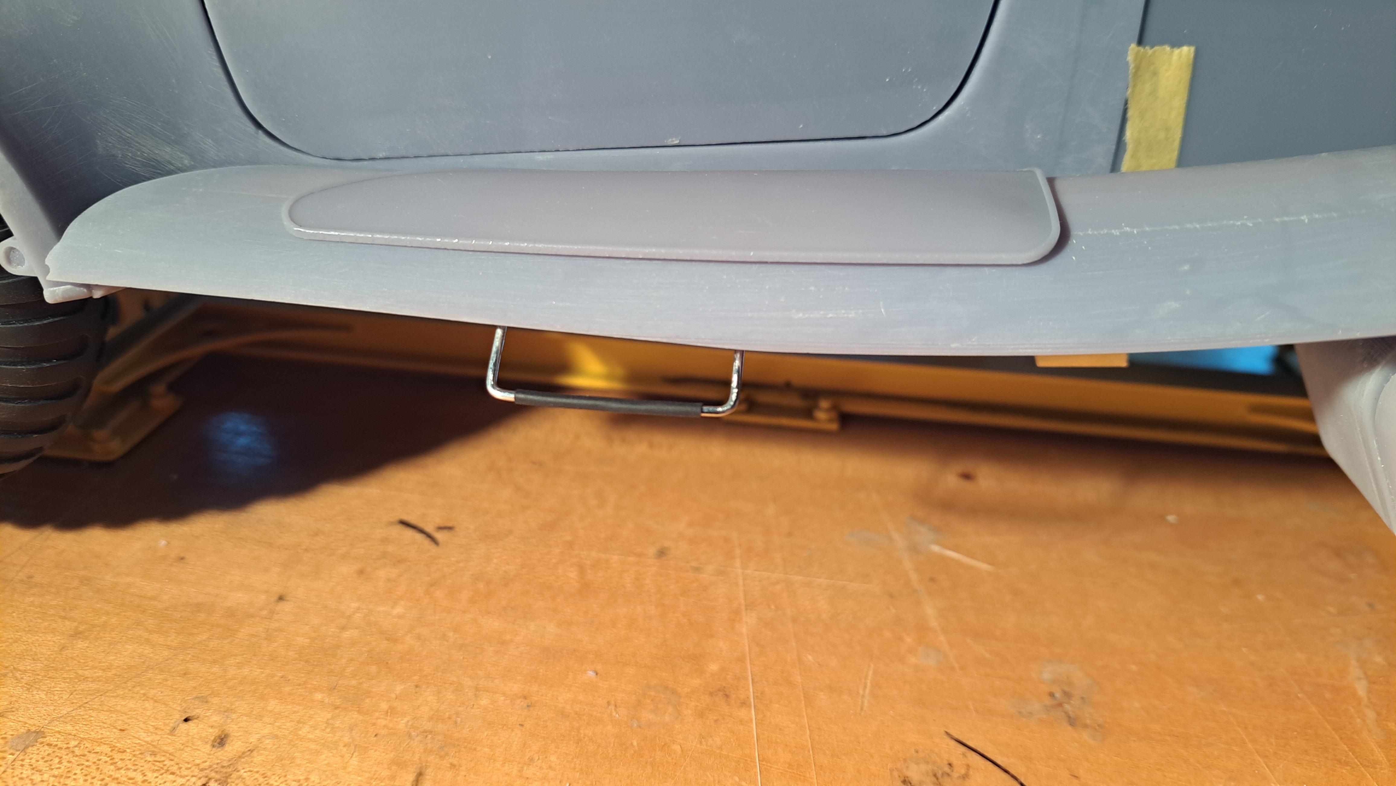
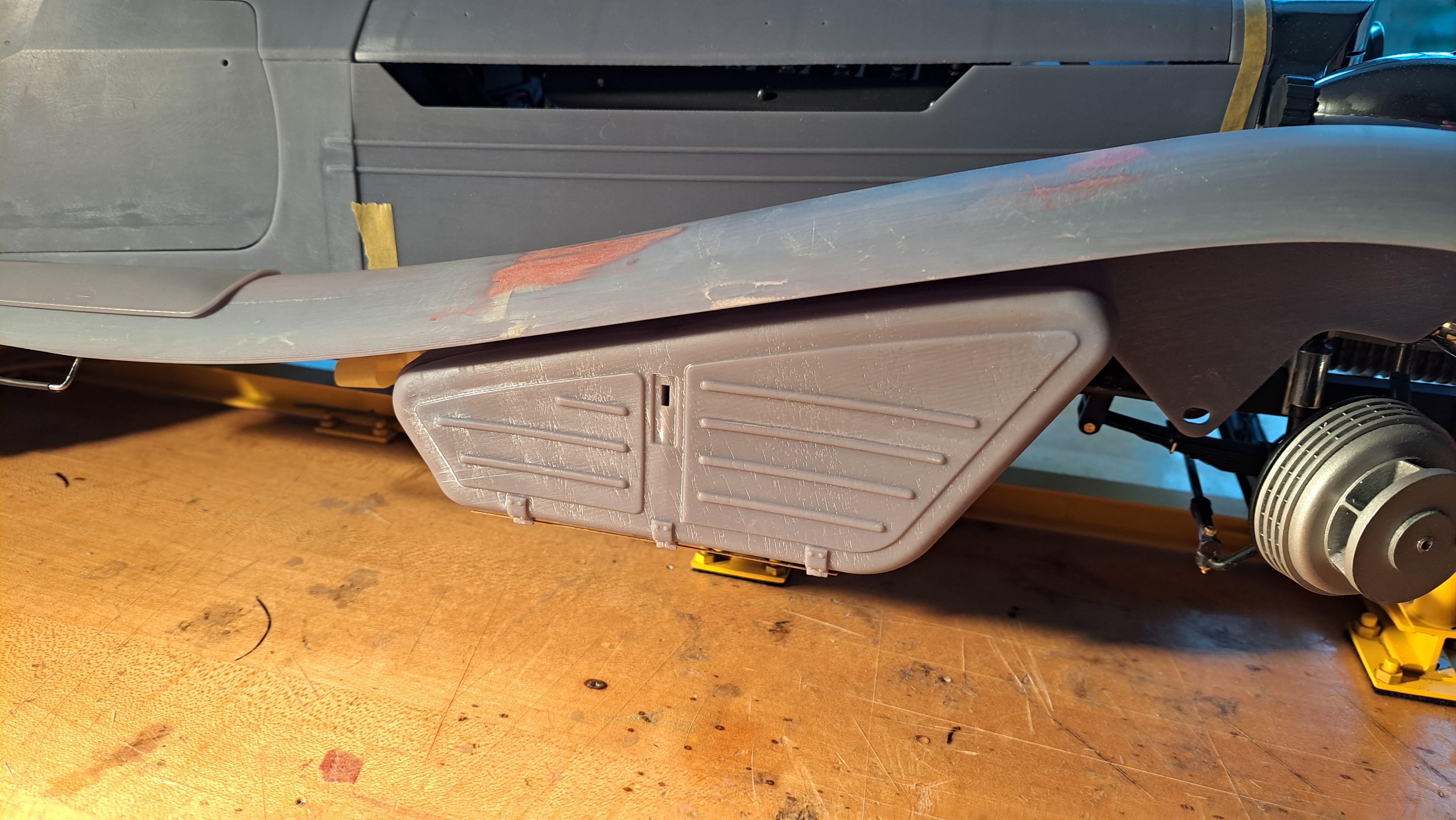
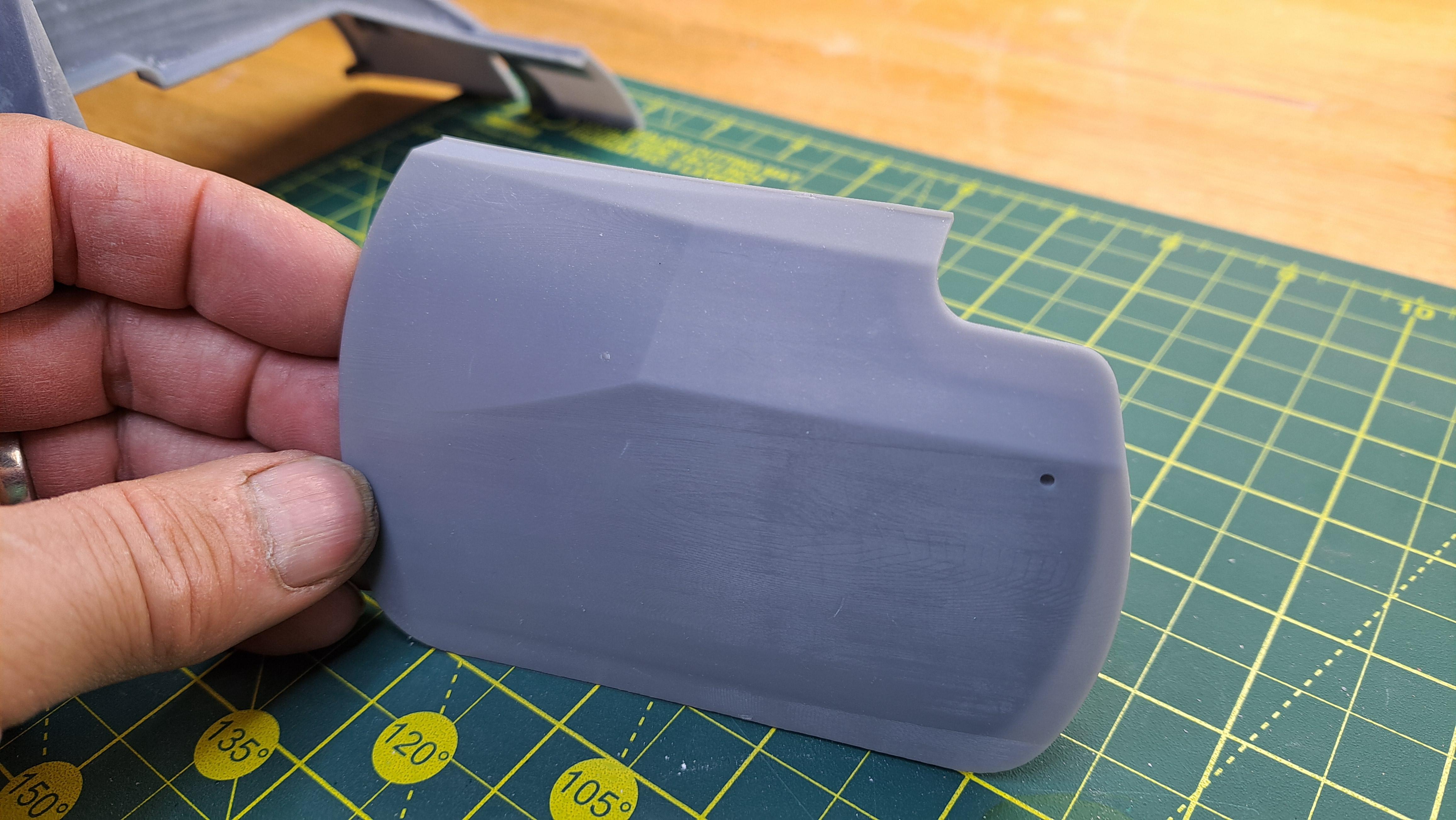
Did a bit more work on the Hydra Coupe today, both under-fender cases are printed, as is the fender step mats. I also did the fender step ladders and wired the rear brake lights. I'm almost done with pre-primer sanding and should be ready to prime pretty soon. I still need to print the rear wheels side covers but not a big deal. Side case Step mats and ladder Wired brake lights Body parts ready for primer
-
Marvel's Hydra coupe 1/12 scale full scratch build
François replied to François's topic in WIP: Model Cars
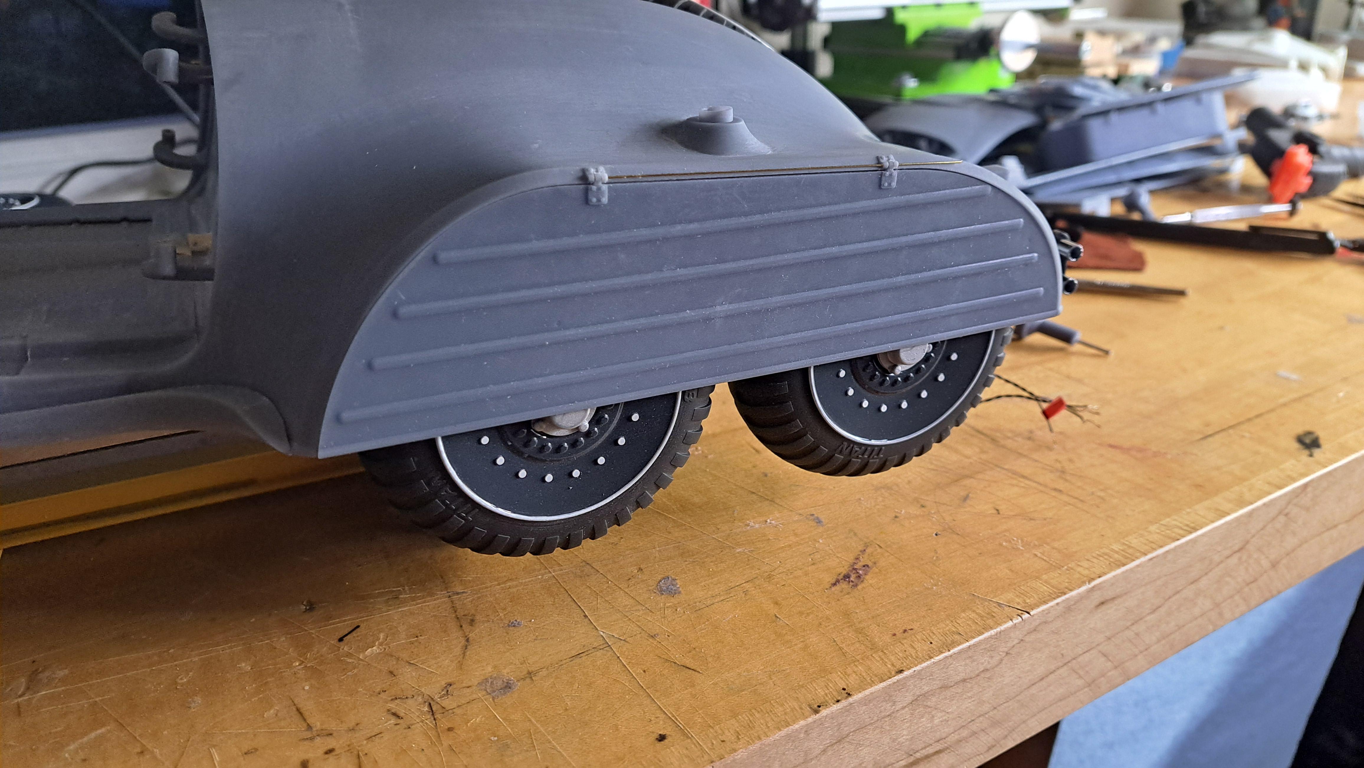
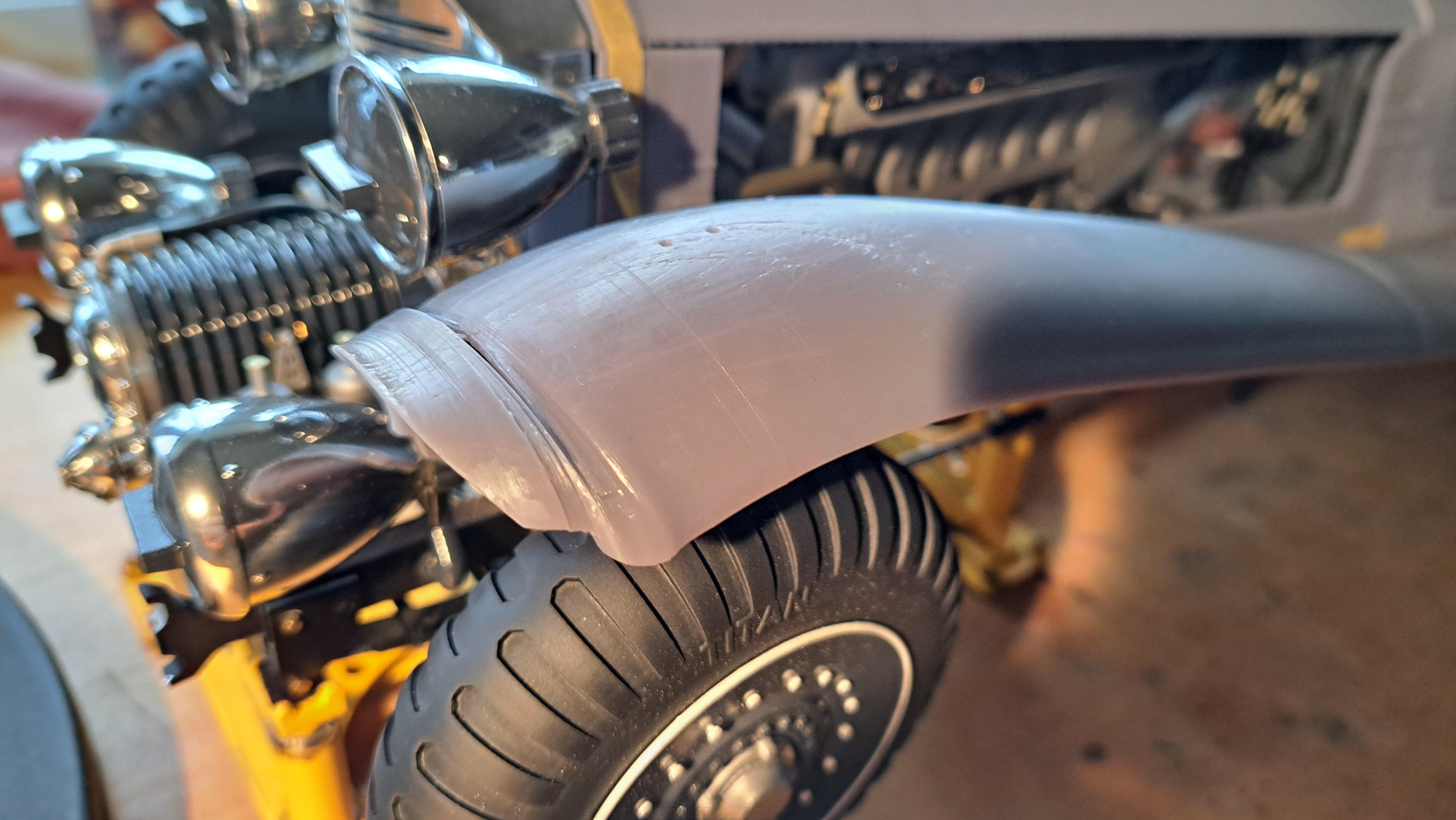
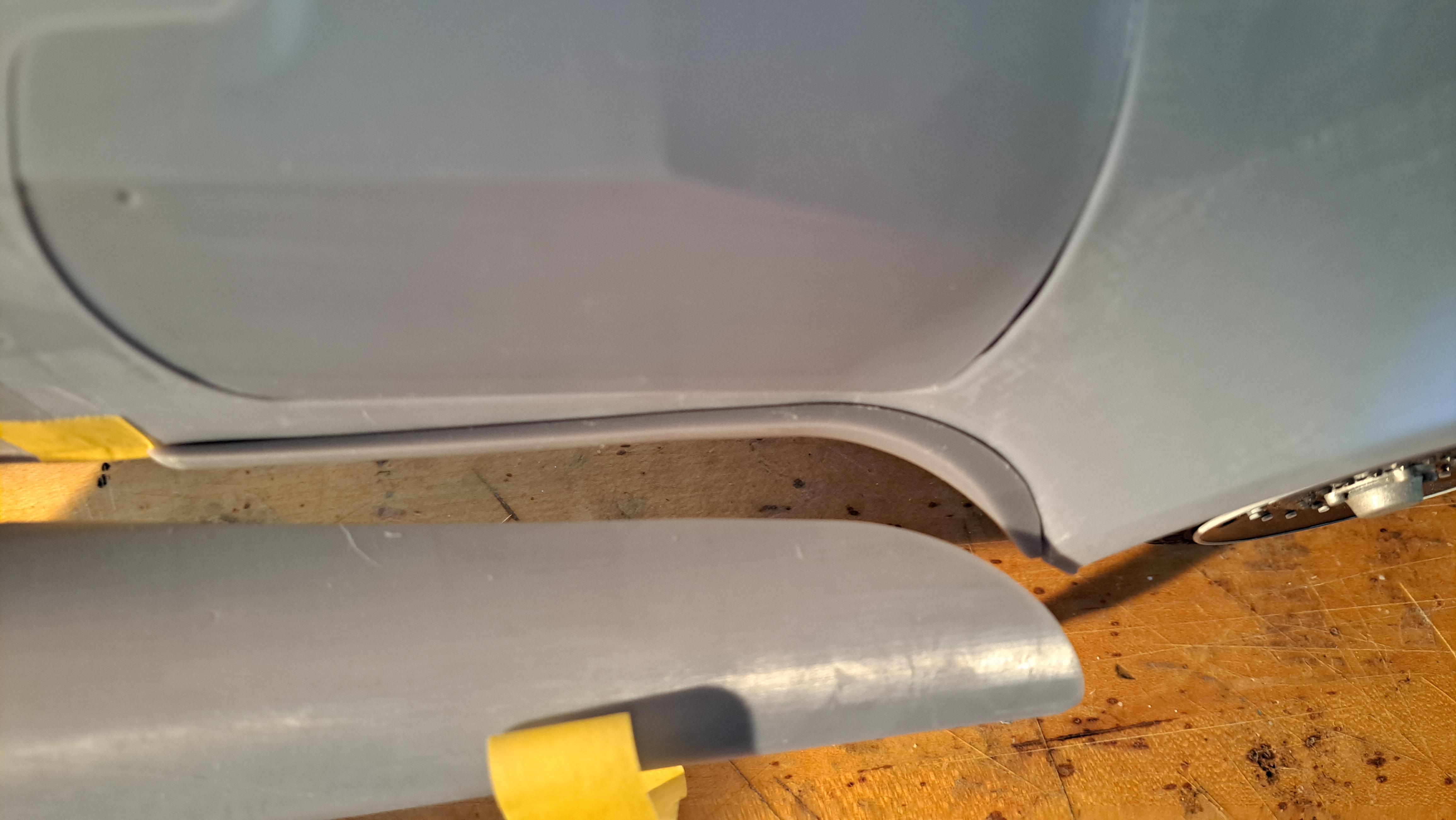
The second fenders print did the trick. The fit is pretty good althought I'll have to wait till the final assy to properly align everything.
-
Marvel's Hydra coupe 1/12 scale full scratch build
François replied to François's topic in WIP: Model Cars
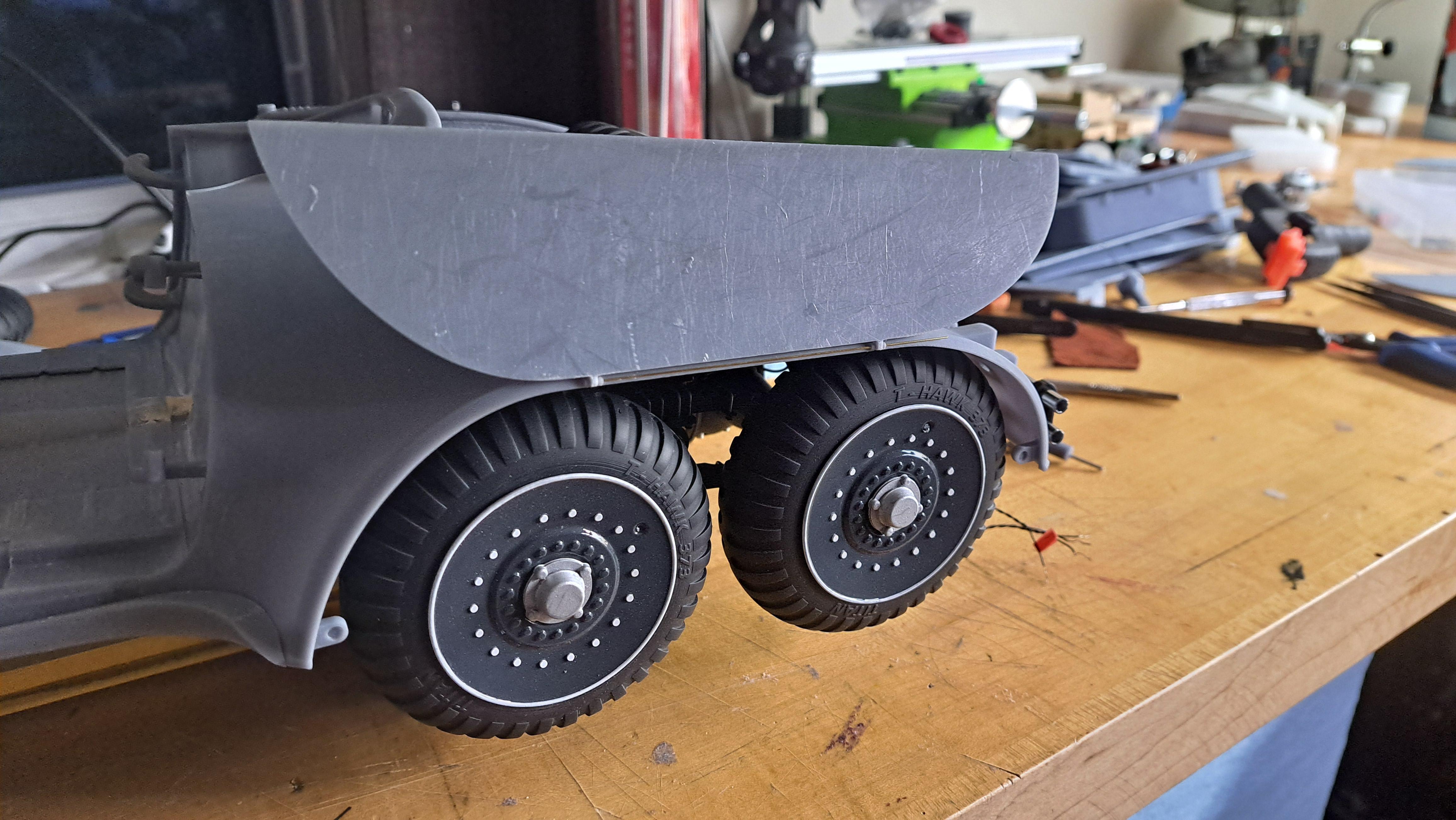
The fenders on this project were among the hardest to 3d model and they prove to be just as difficult to print. They are also very big so they need to be printed in 2 parts. My first try didn't come out so good. I printed the left side fender and althought it has good dimensions and fits as it should, the front amd middle were badly printed. I'm hoping the second try will do better. It wasn't easy to properly locate it again the body so I made a hook up rail that fits perfectly against the body and is glued there. The inside edge of the feeder can then be hooked on the rail in order to be in the correct spot. Hook up rail glued to body Fender edge near rail Front of fender badly printed But it's promissing
-
Marvel's Hydra coupe 1/12 scale full scratch build
François replied to François's topic in WIP: Model Cars
Thank you everyone for the positive feedback. Big John, the shield is printed on the inside so it's not visible when the lid is closed. I want it to be discret. -
Marvel's Hydra coupe 1/12 scale full scratch build
François replied to François's topic in WIP: Model Cars
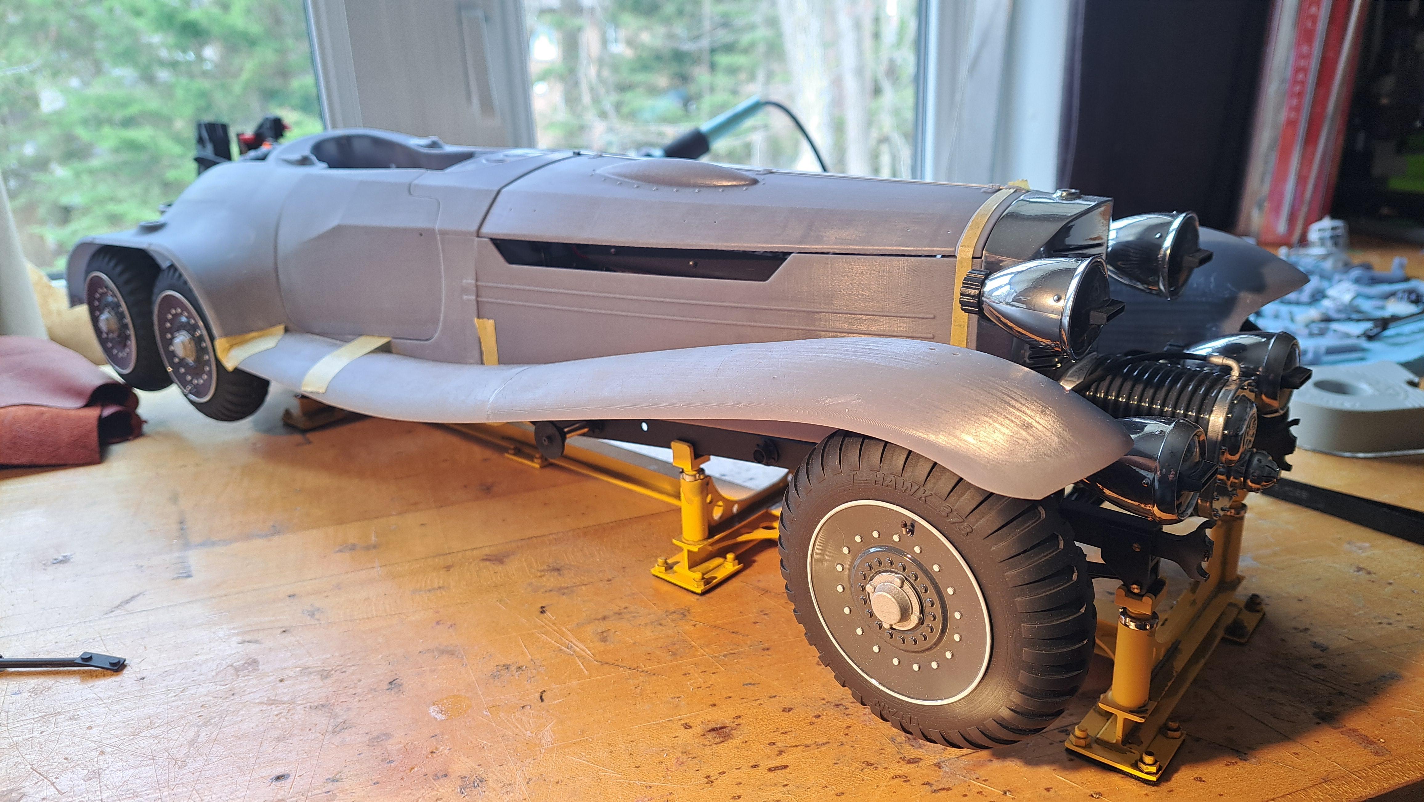
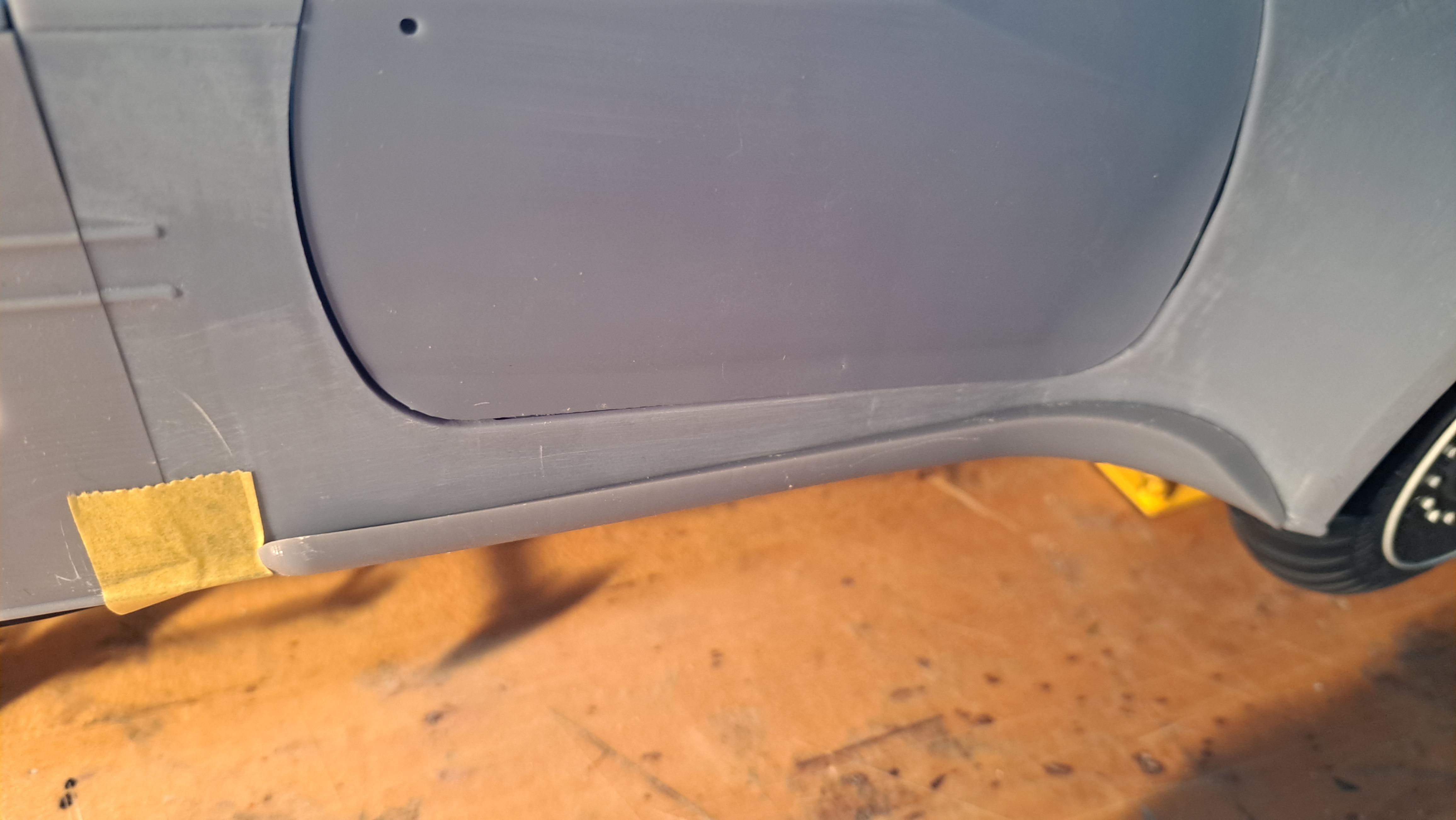
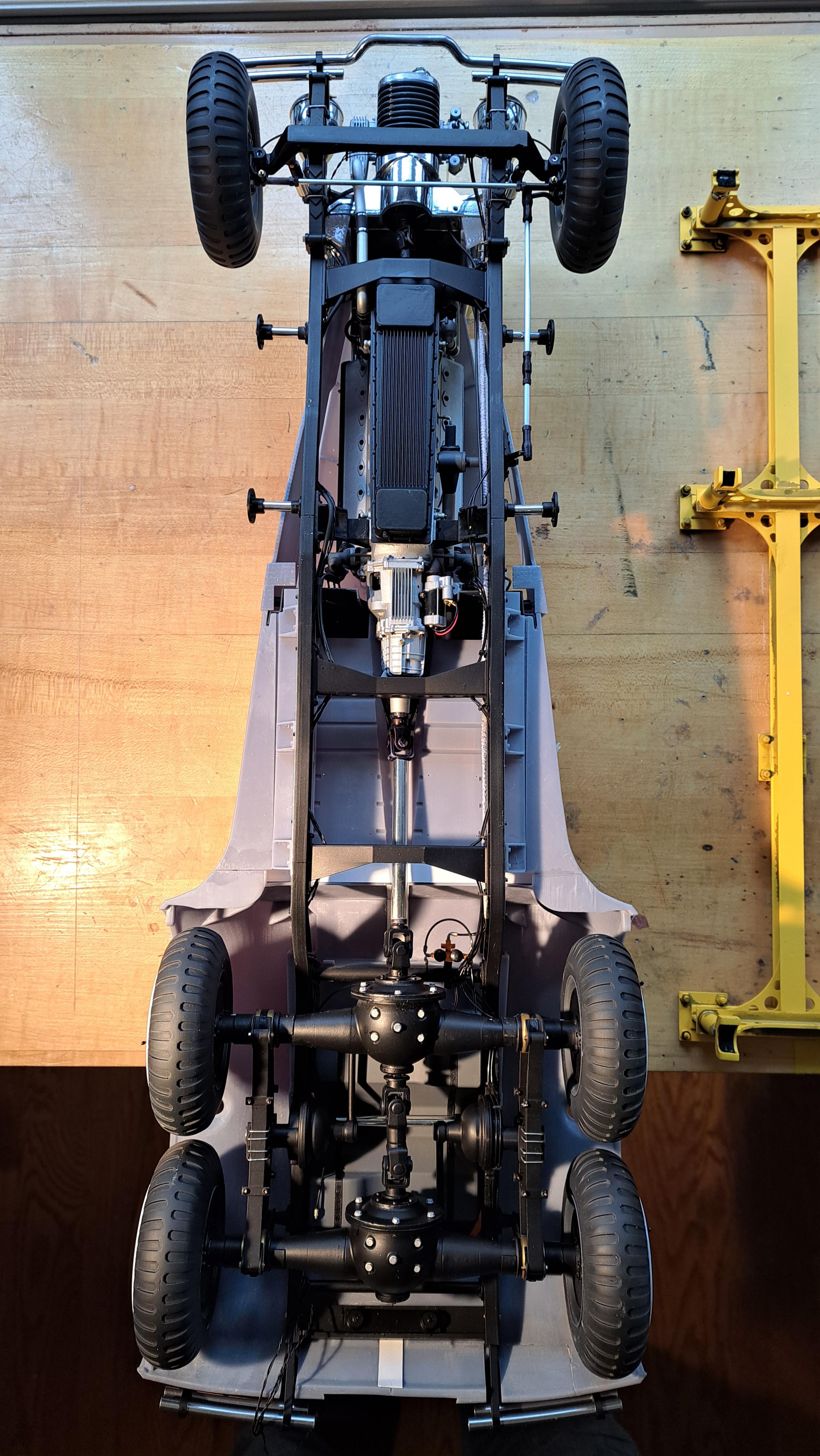
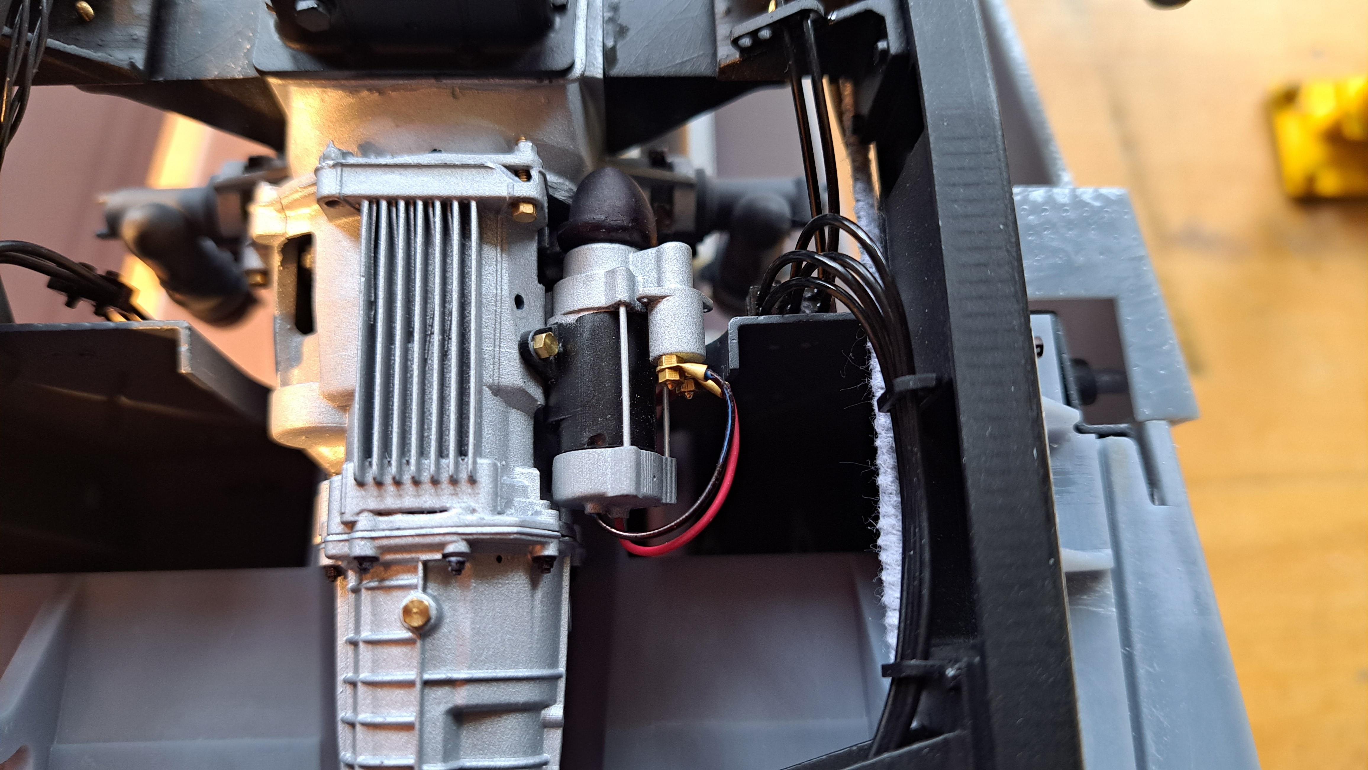
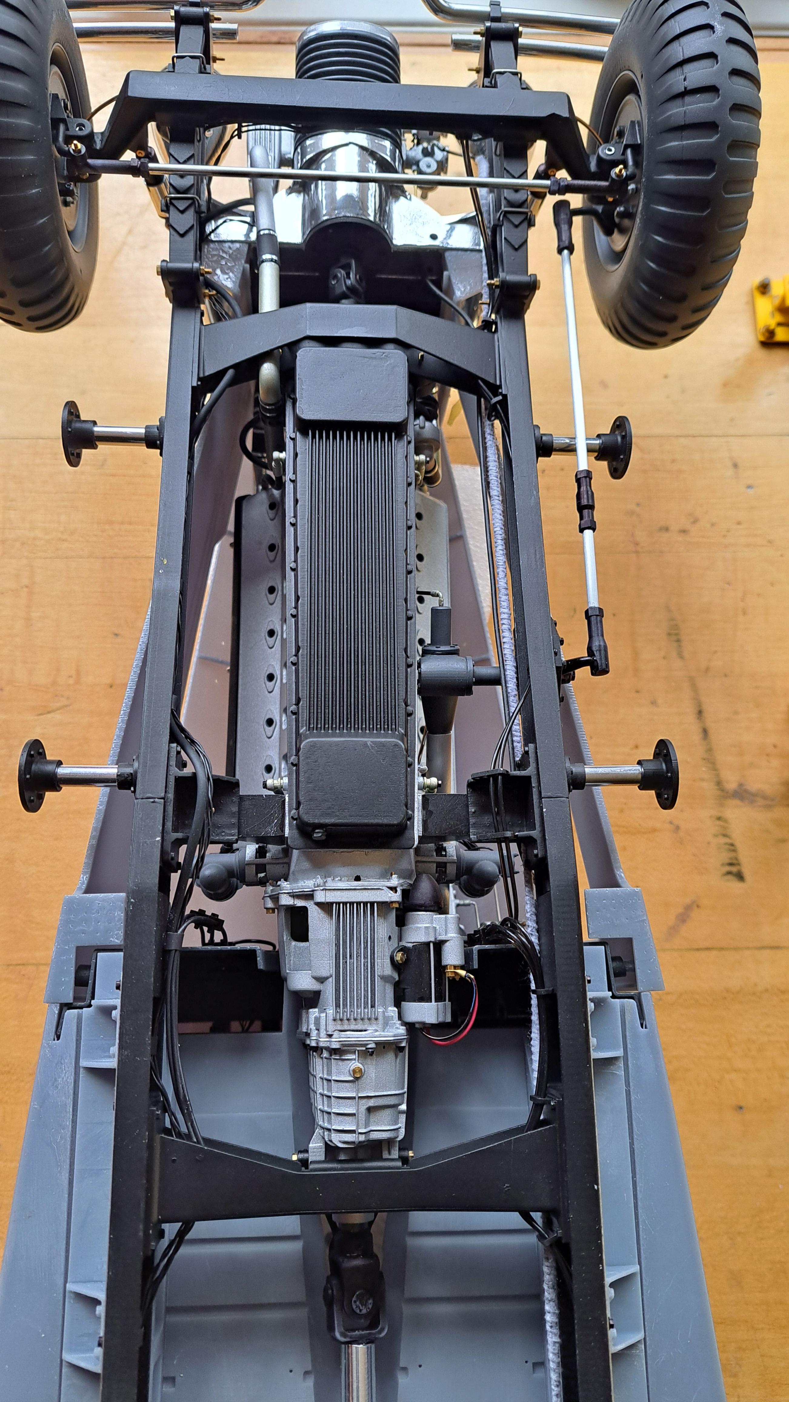
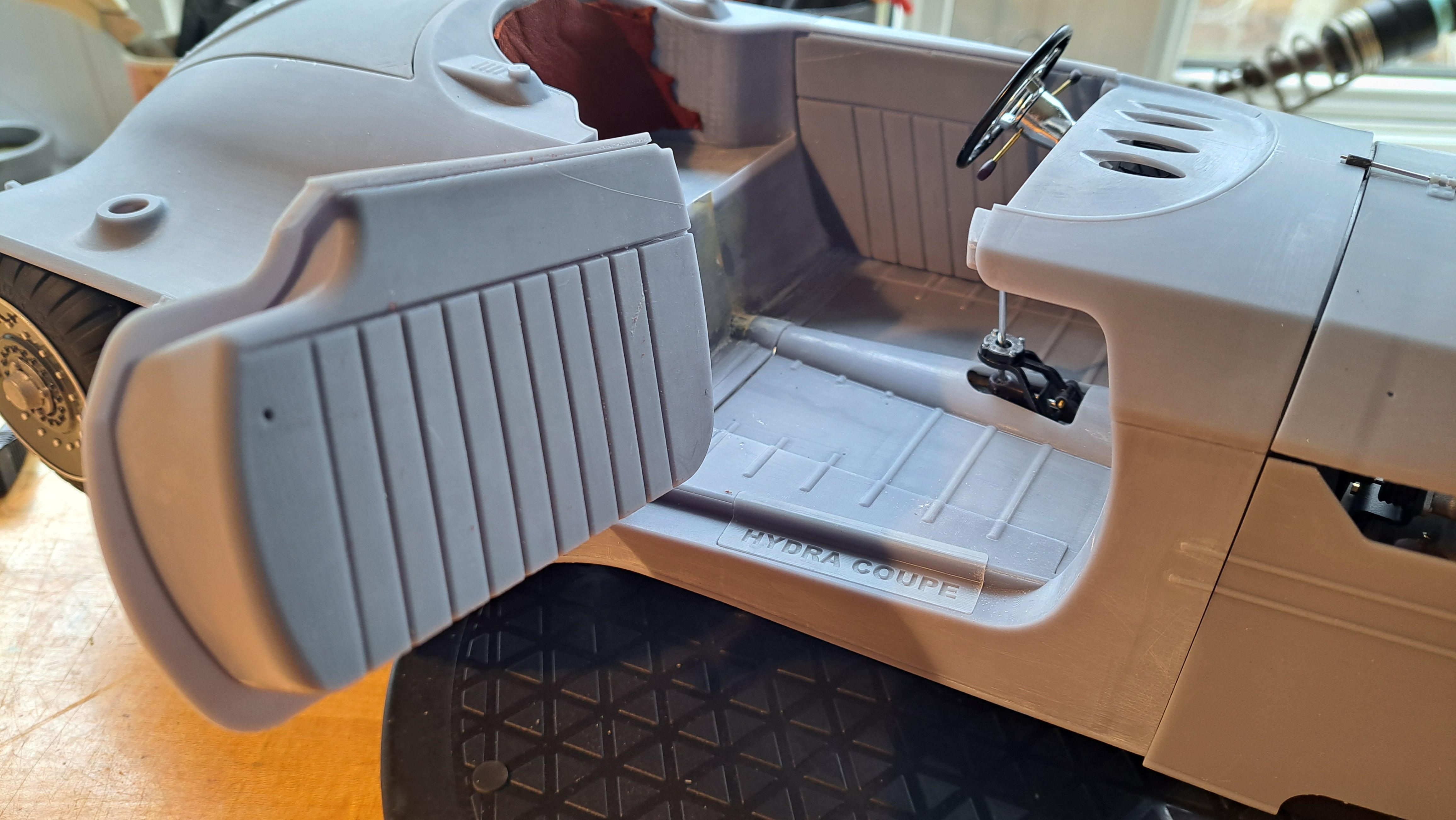
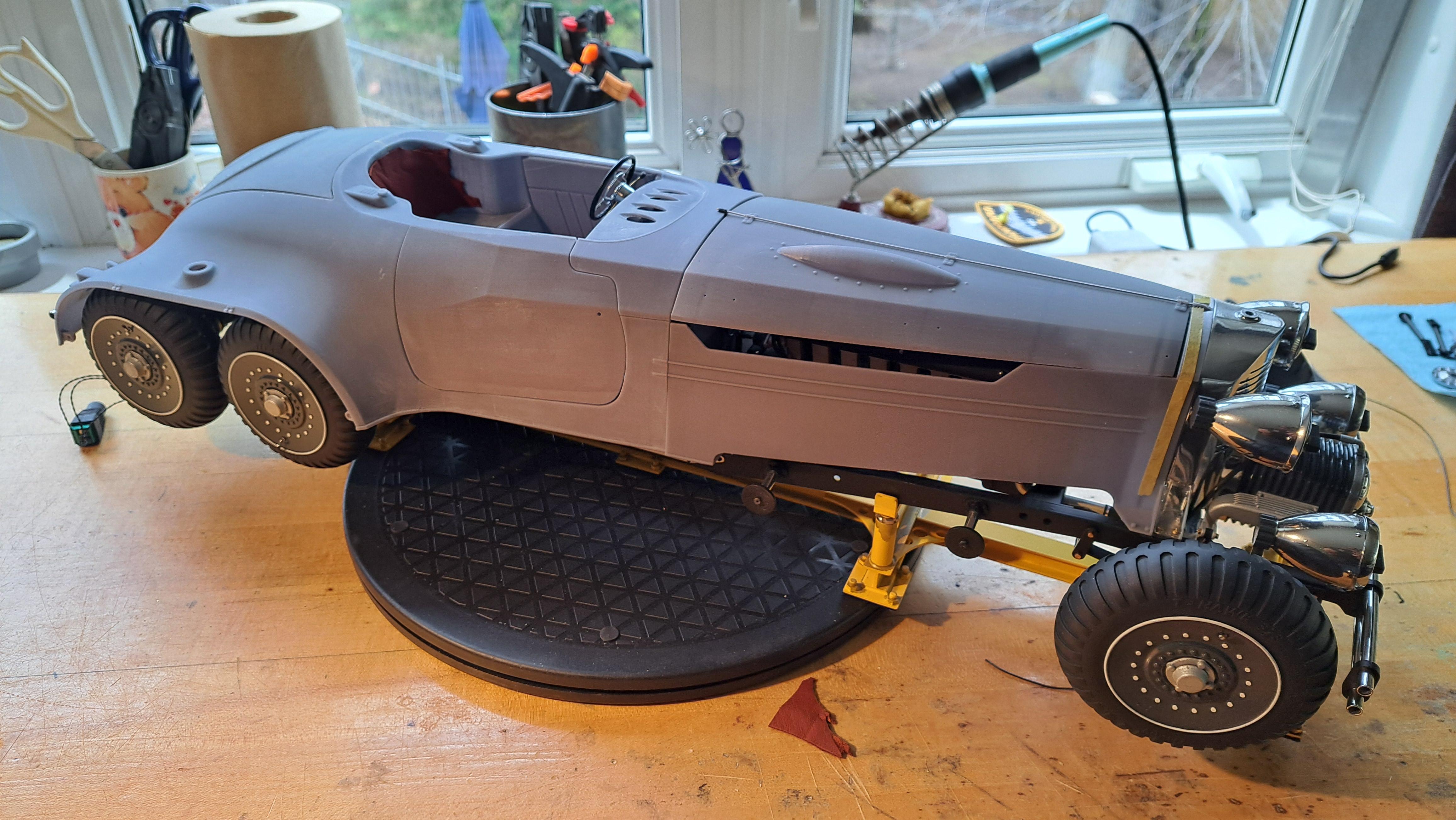
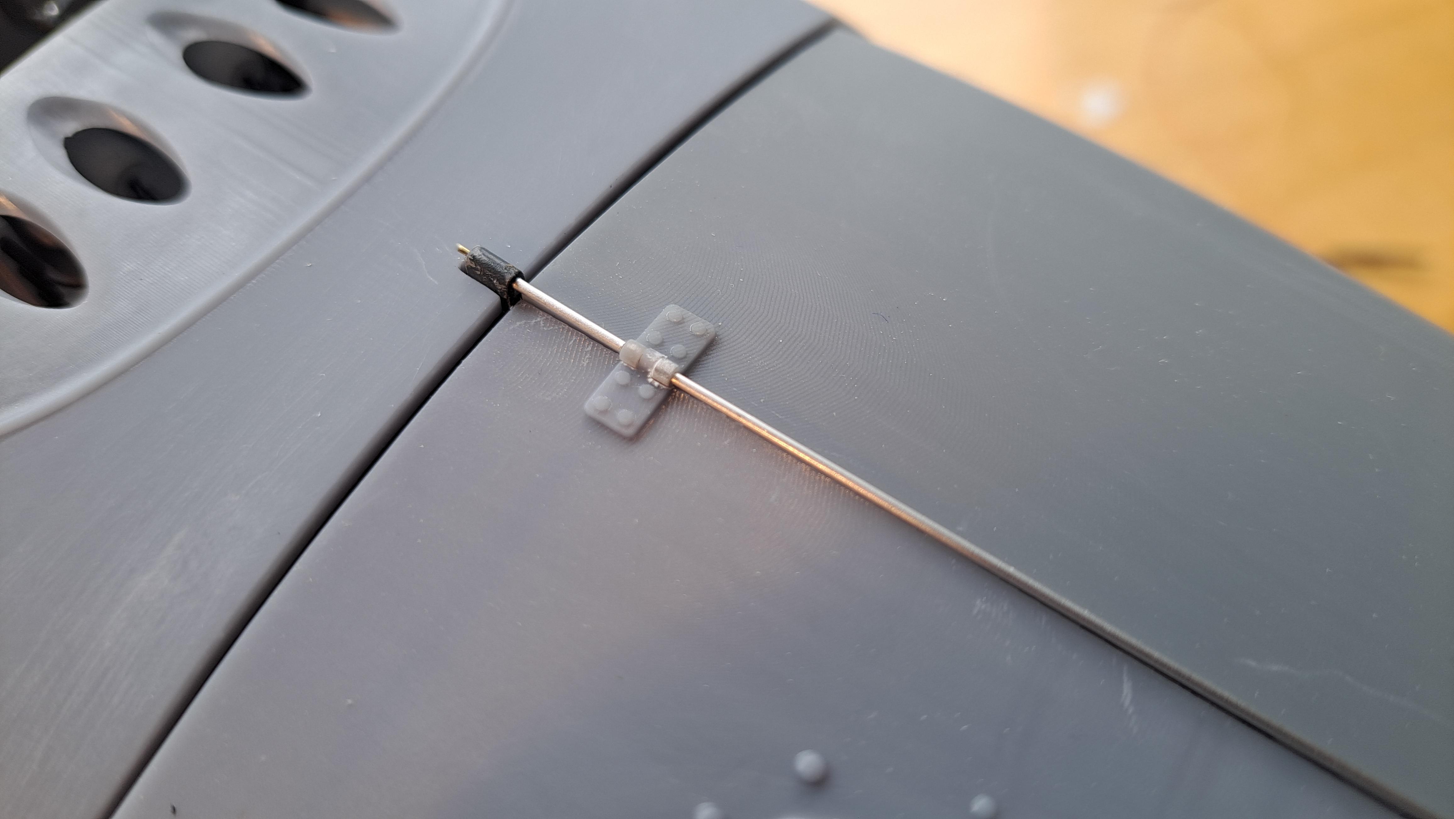
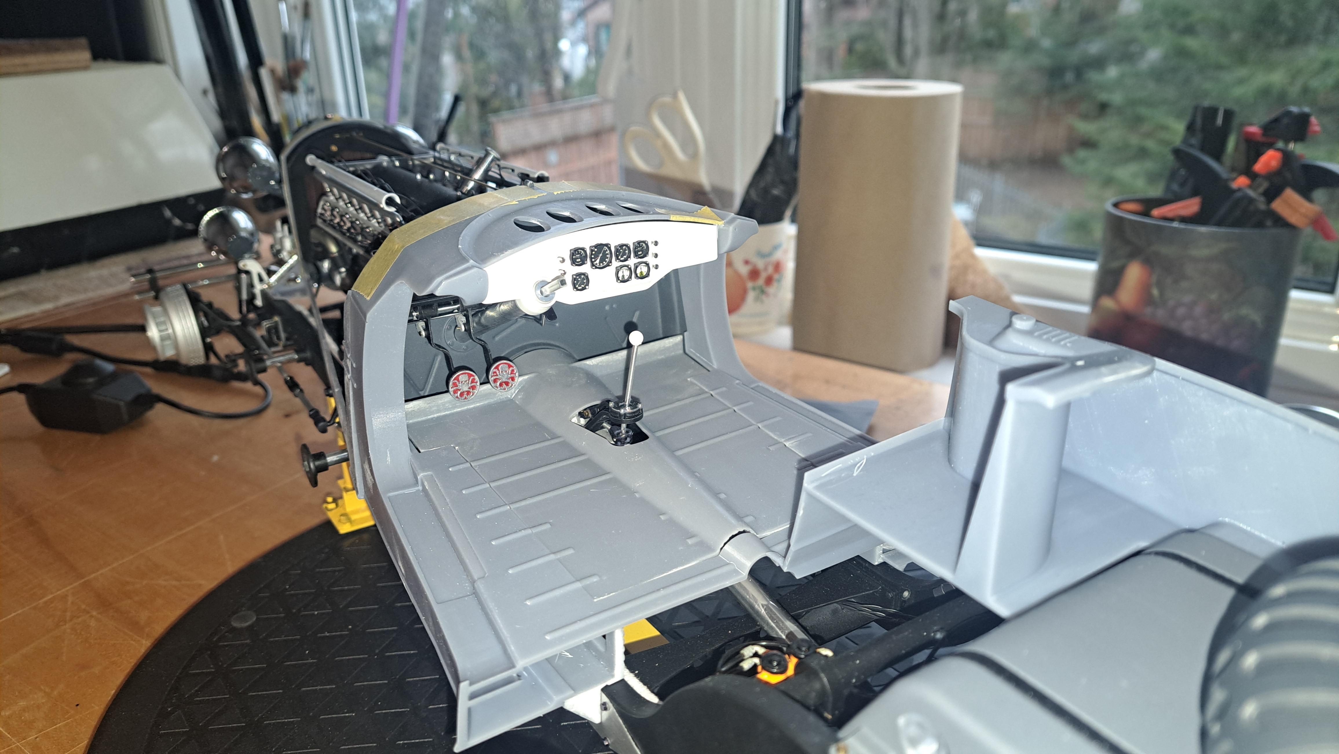
The body is slowly coming together, and the fit is surprisingly good. The doors open and close easily as does the trunk lid. I still have a lot of fitting and sanding/puttying to do. I'll ve applying a sandable primer before paint. Here are some shots as of today. I also took a few shots of the undercarriage. Door sill, will be chromed with black lettres 20250502_140340.mp4 Trunk lid prop bar added aluminium micro tubing over brass pivot rod Leather trial, it's a nice reddish brown that I think should look pretty good with the gun ship gray of tge body Undercarriage Close up of the wired starter
-
Marvel's Hydra coupe 1/12 scale full scratch build
François replied to François's topic in WIP: Model Cars
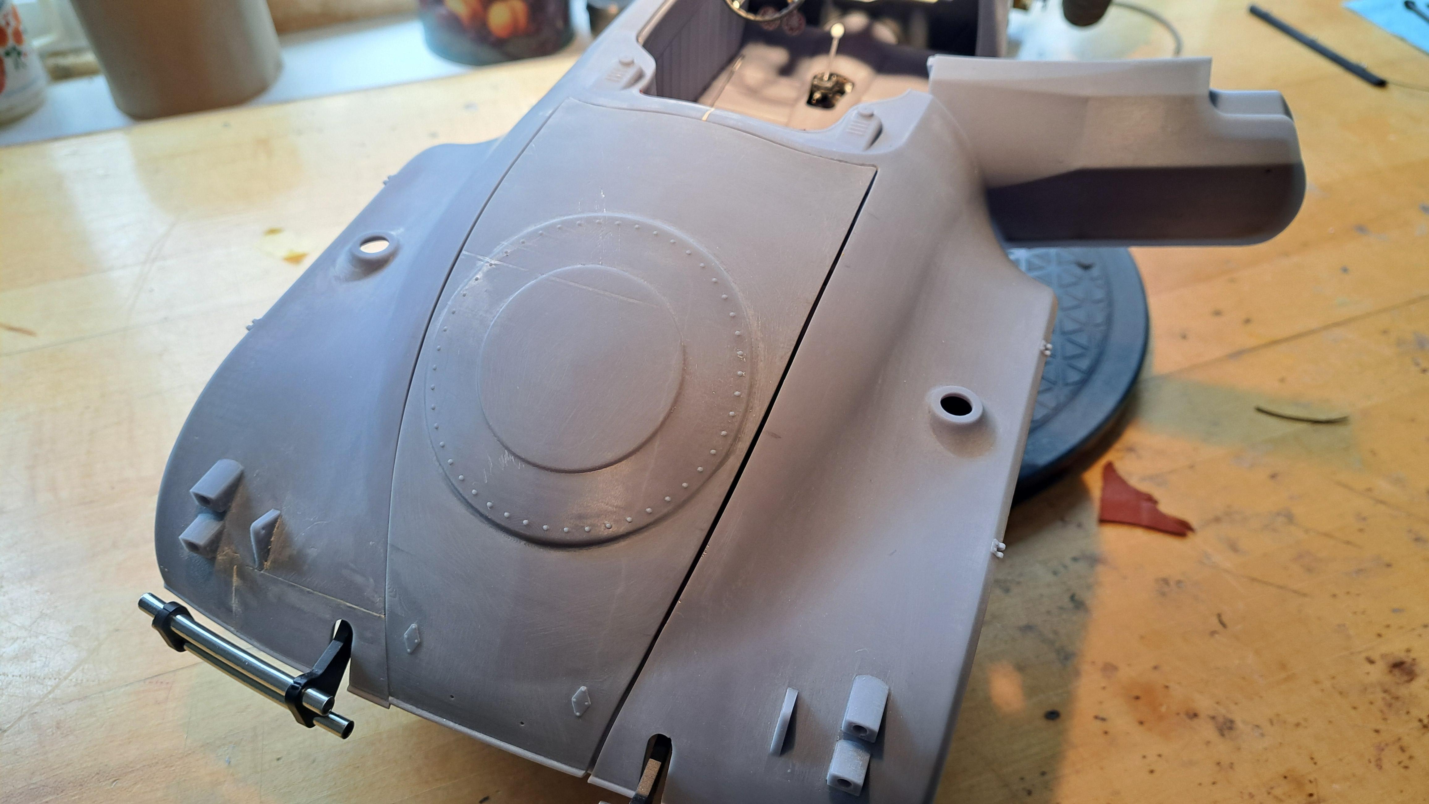
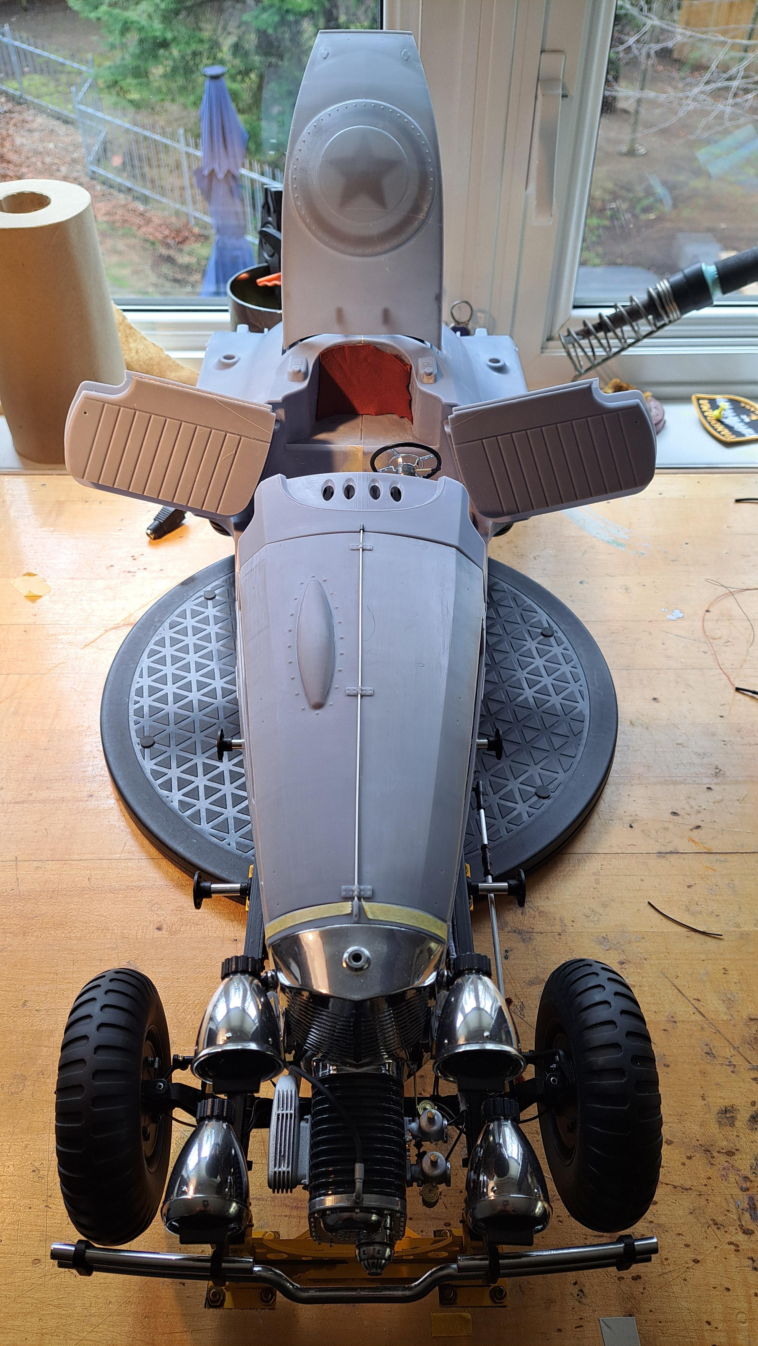
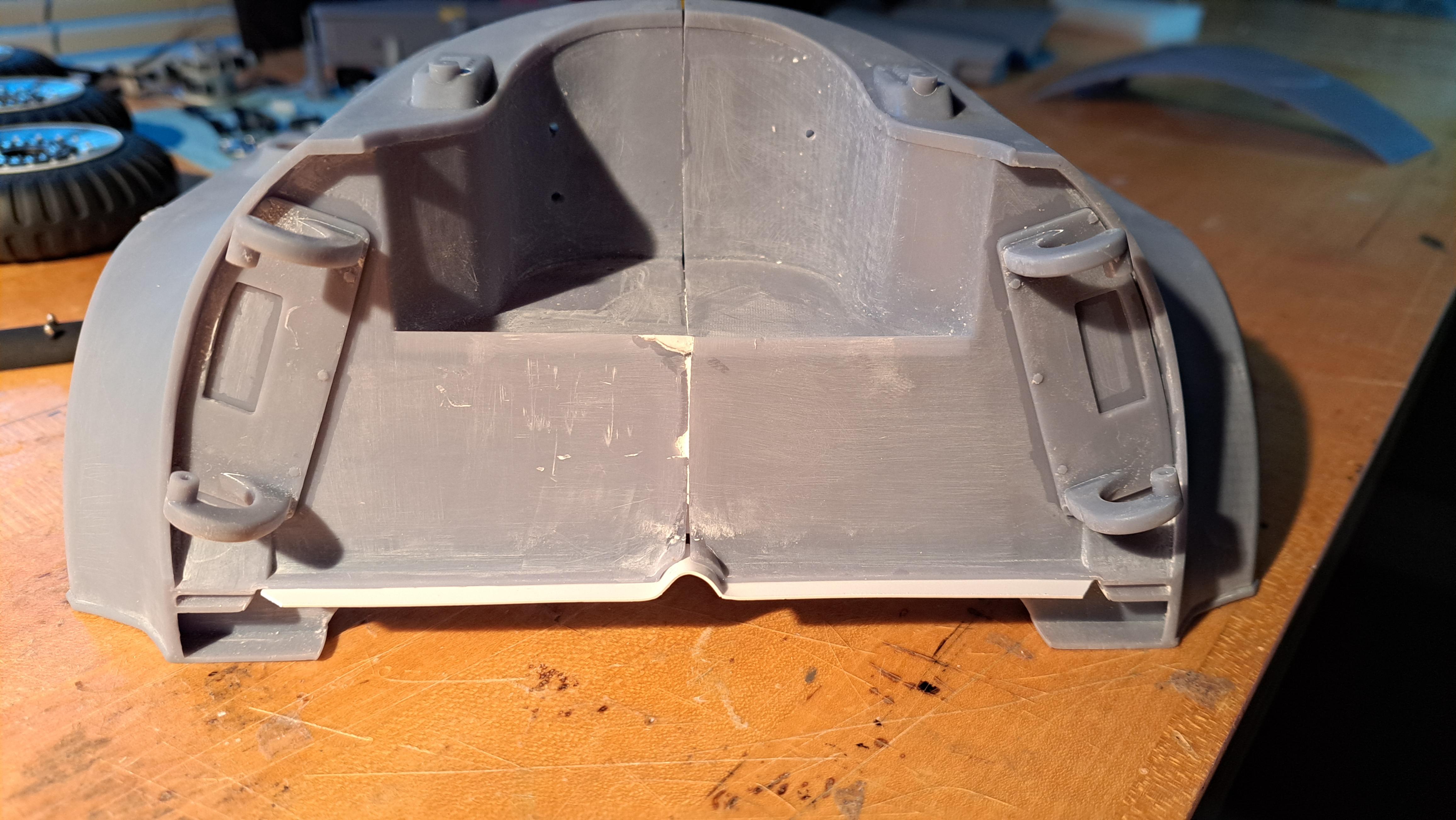
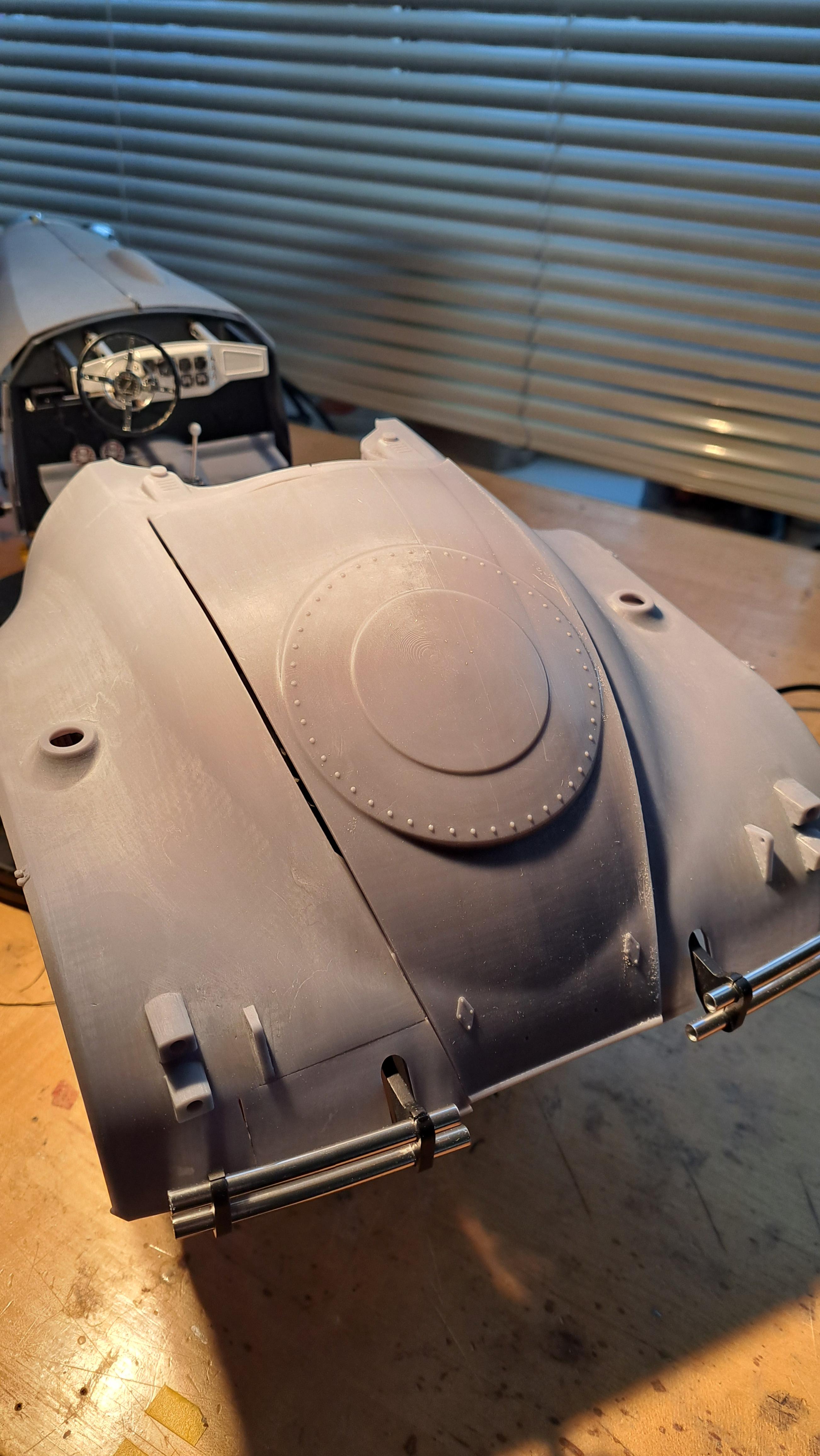
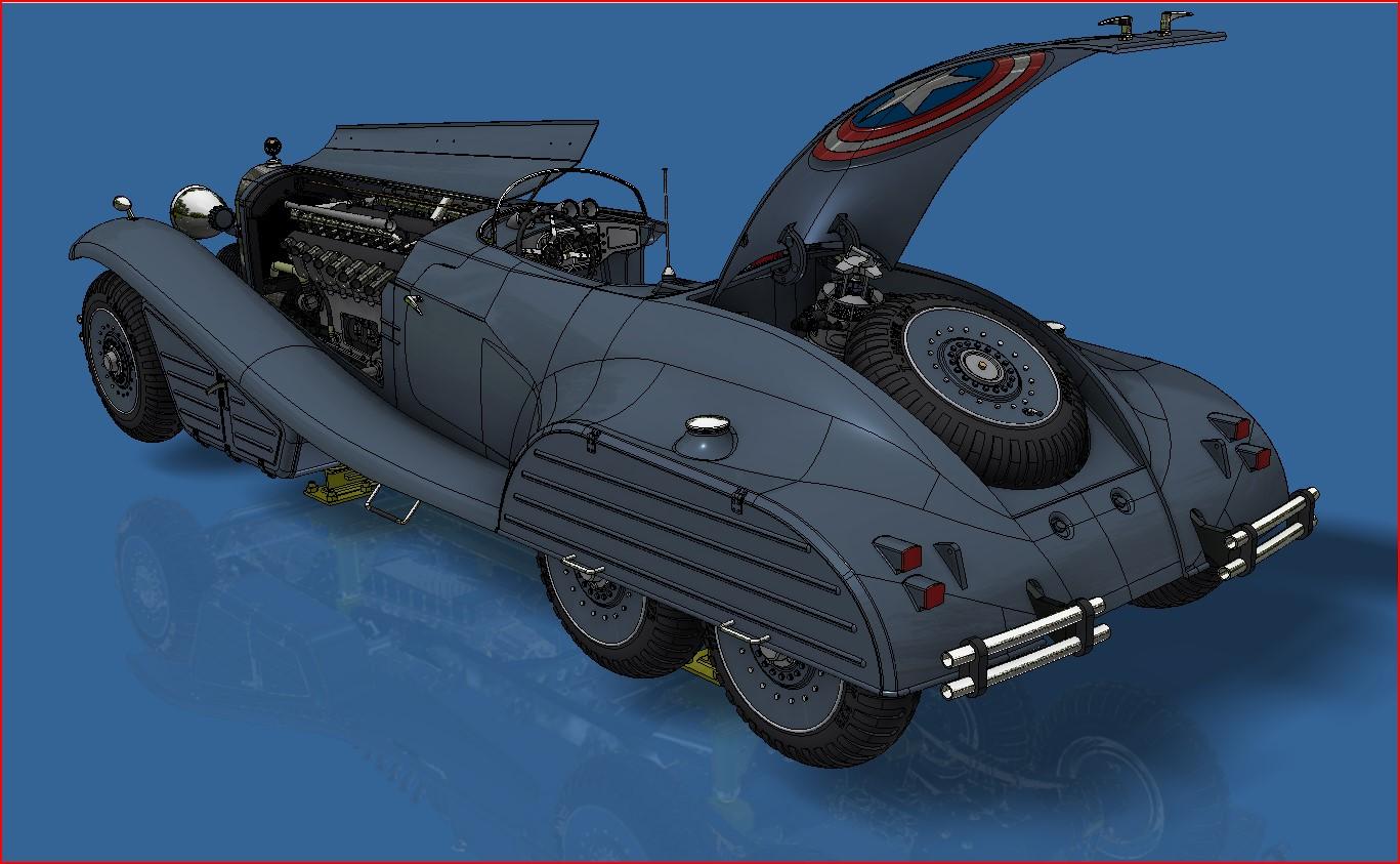
It's update time. I started gluing up tge body together. First is the rear two halves. I installed some fish plates to better align the two halves and to get more gluing surface. It came out good, is rock solid and very well aligned. I'll need to do a bit of epoxy putty on the seams and gaps but I think it should look pretty good. Both door hinges are glued in and I even added some rivets to the only fish plate that will be visible (with the trunk lid opened). I also printed the trunk lid but it's not to my liking, I added some longitudinal stiffeners to the new one that should help to better maintain the shape. But even with it not being perfect, it still looks good. Two halves glued together with white styrene fish plates in place Riveted fish plate Hinges installed Test fitting of the bleu cube thingy which fits as planned test fitting of not perfect trunk lid captain america's shield cameo And a few general pictures
-
Marvel's Hydra coupe 1/12 scale full scratch build
François replied to François's topic in WIP: Model Cars
I'm glad you appreciate my work, -
Marvel's Hydra coupe 1/12 scale full scratch build
François replied to François's topic in WIP: Model Cars
Thanks BK, I found the problem, there was a tear in the film on the botton of the resin vat which means that the resin was leaking onto the screen. I was very lucky that the leak was minor. It's an easy fix. -
Marvel's Hydra coupe 1/12 scale full scratch build
François replied to François's topic in WIP: Model Cars
Second try is much better but there's a hole in one of the parts and I have no idea how it got there. I think I'll add another. 010" to the thickness.
-
Marvel's Hydra coupe 1/12 scale full scratch build
François replied to François's topic in WIP: Model Cars
Thank you Chris I printed the hood today, really not a success. At .030", they are way too thin. I reprinted with a .050" thickness and with stiffener ribs. I think it should help. But at least, the pivot works
-
Marvel's Hydra coupe 1/12 scale full scratch build
François replied to François's topic in WIP: Model Cars
Reprinted the doors with thicker outter panel and it is now perfect. I also beefed up the hinges a bit. I did a preliminary test fitting of the door on the rear body and it looks like it will work. 20250424_203951.mp4
-
Marvel's Hydra coupe 1/12 scale full scratch build
François replied to François's topic in WIP: Model Cars
All major body components are printed. I had another issue with a rear body half ( problem with the U shaped cutout for the bumper) but this time I was able to repair it. I printed a patch and replaced the section. Still needs a bit of putty but it should be ok. Also printed a test door, the outter sheet is too thin. I'll have to thicken it a bit. I decided to print the outter sheet and inner panel as a unit. Once painted, I'll be able to apply the leather. Speaking of leather, I found a piece of nice thin brown leather that should look pretty good. Rear end repair And once repaired Test door Door hinge insert And so far The brown leather -
Marvel's Hydra coupe 1/12 scale full scratch build
François replied to François's topic in WIP: Model Cars
Since the bentley and this car are both 1/12, I barrowed the seats from the Bentley to see how they fit in the cockpit. The size is pretty good, but the Bentley's seat are small to begin with. I'll widen them a bit and it shoul be ok. The Bentley's tub next to the Hydra's just for fun
-
Marvel's Hydra coupe 1/12 scale full scratch build
François replied to François's topic in WIP: Model Cars
The body is slowly being printed. The rear end is quite big to print, even in 2 halves. My first try didn't work. But still, it's starting to look like something a vilain would drive. First rear end half print, close but no cigar. It's as if the max printing volume the slicing program gives me is incorrect, the top of the part didn't print (circled in red). It took over 12 hrs to print and 500 ml of resin, oh well... But still, it's getting there For those wondering where this gadget is going
-
Marvel's Hydra coupe 1/12 scale full scratch build
François replied to François's topic in WIP: Model Cars
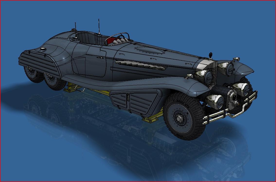
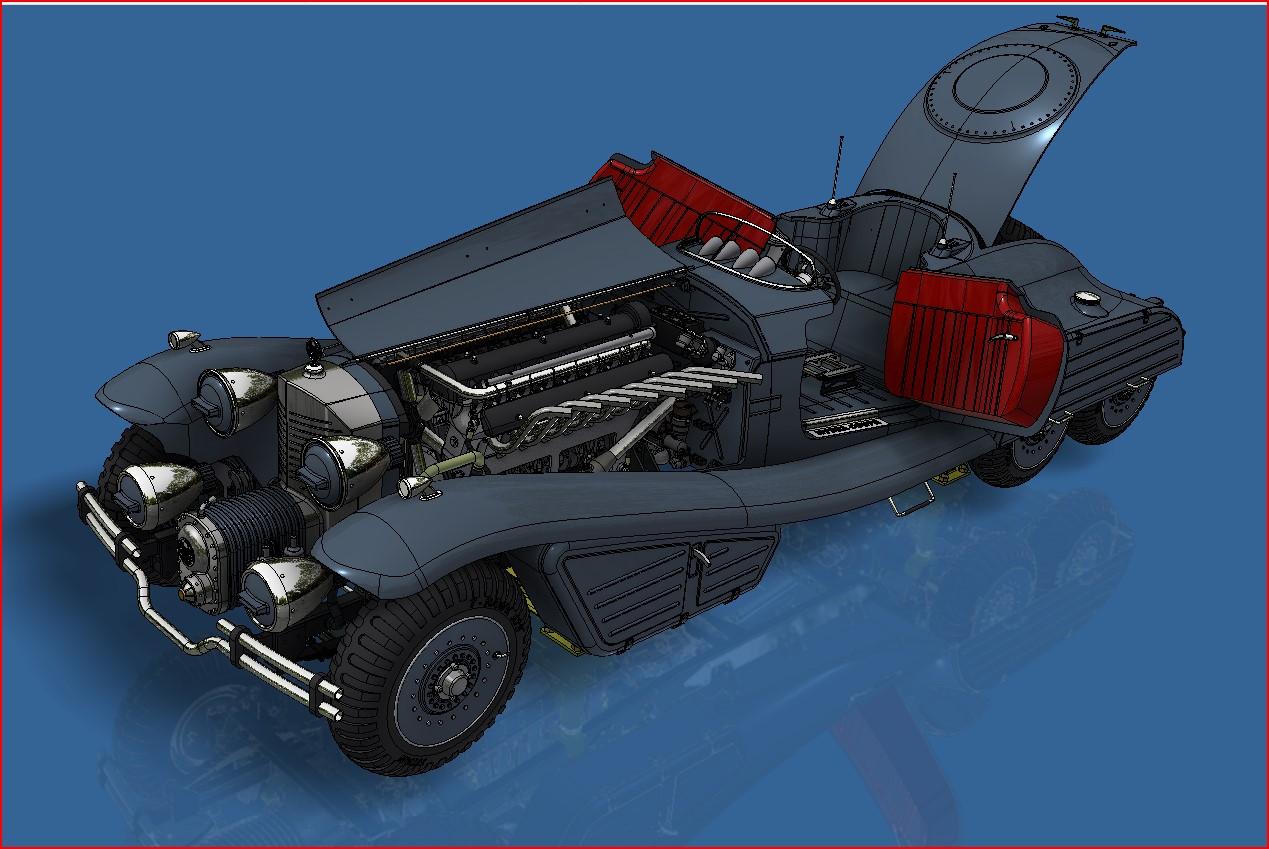
Thank you everyone for your positive comments and insights. So here's the 3d model showing the modified left front body panel that give a good view of the engine. And when seen from the other side
-
Marvel's Hydra coupe 1/12 scale full scratch build
François replied to François's topic in WIP: Model Cars
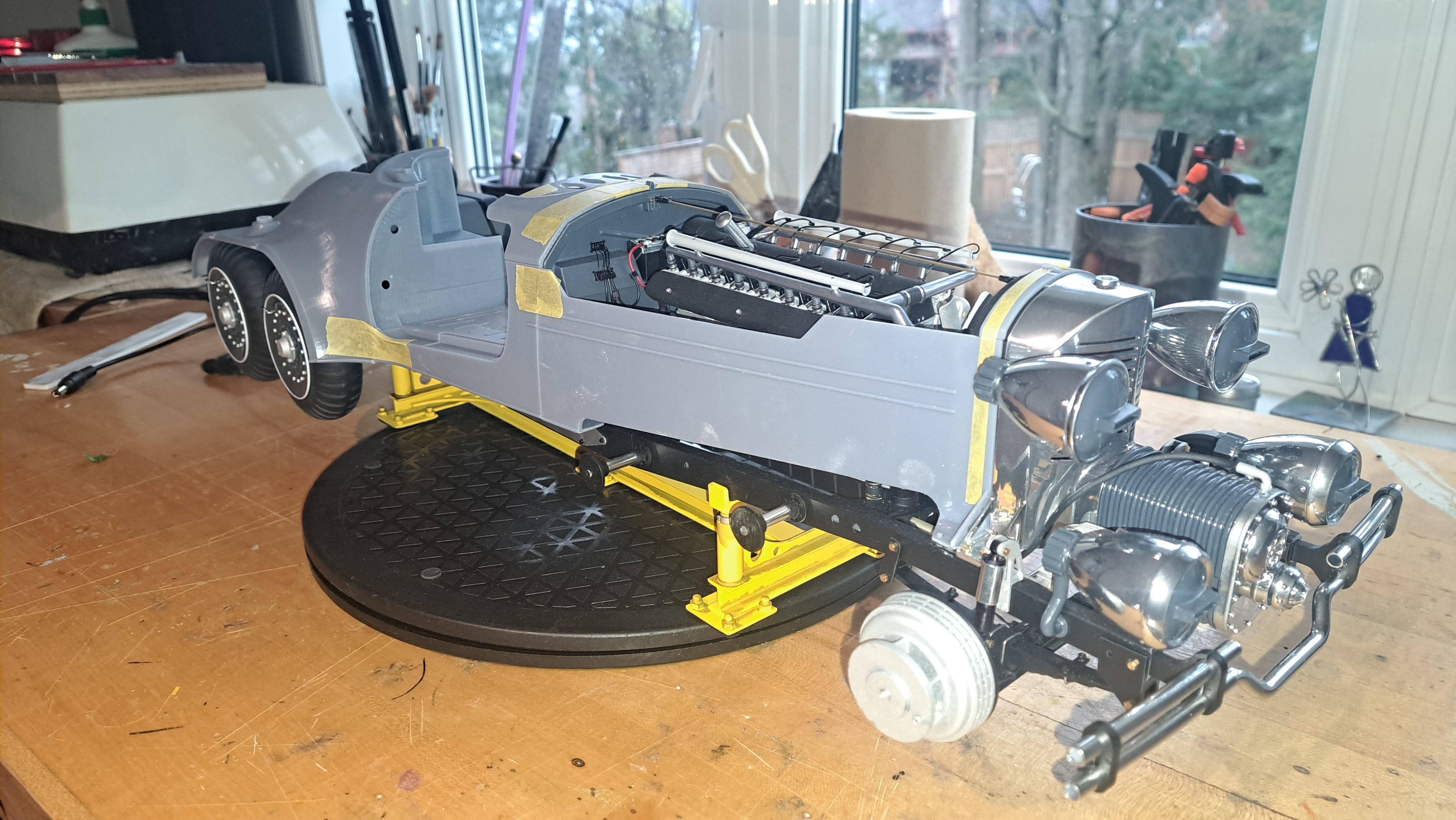
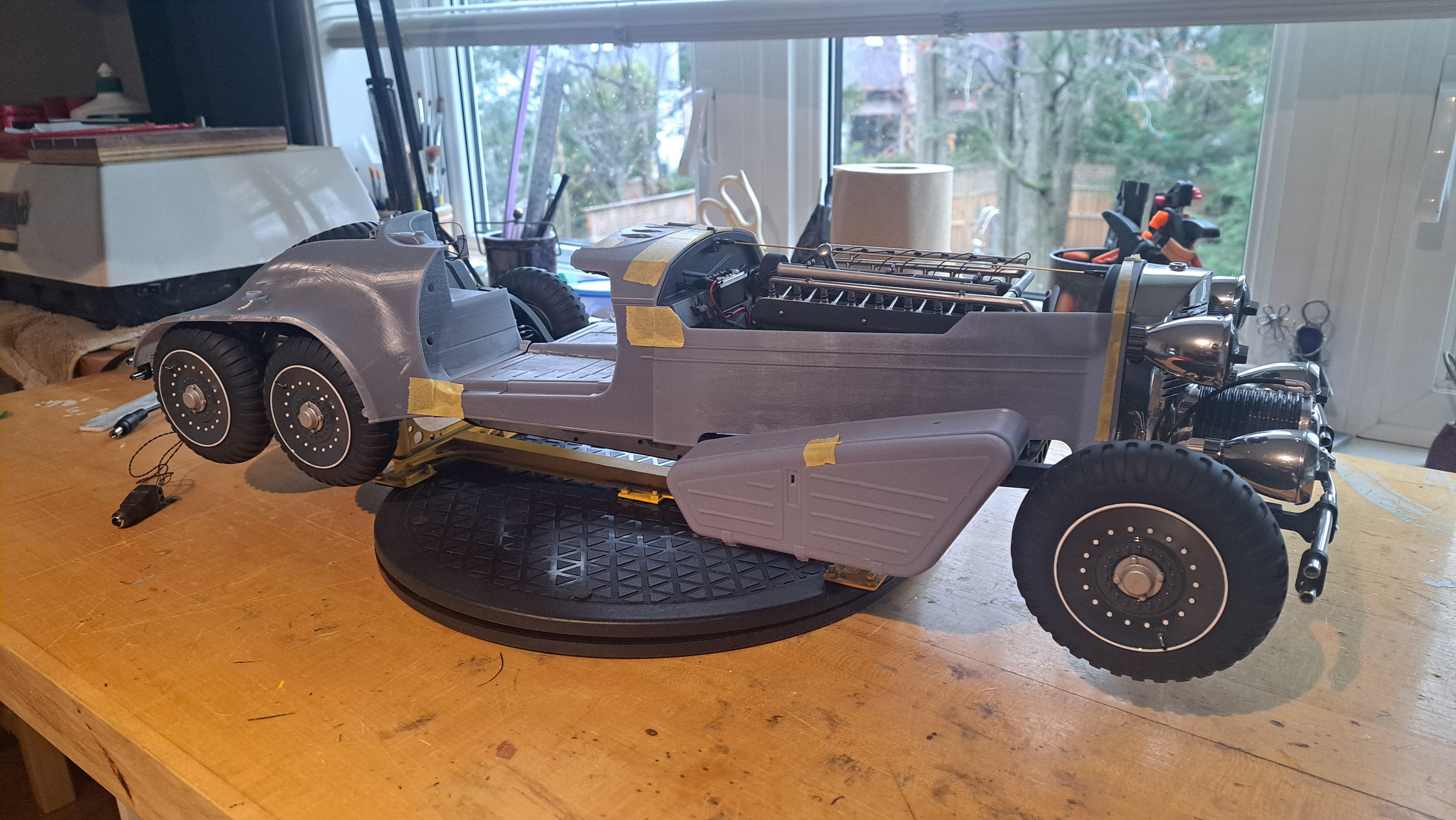
Absmiami, I've already used clear resin but it's not 100% translucide, I would even say it's a far cry from being translucide so that's a no. I post on 3 different forums and explained on all 3 my conundrum. I received plenty on interesting ideas (including yours). But there's one that I think will be best. I'll but the body on the rolling chassis but I'll modify one of the front lower panels to give a good view of the motor and all the bits and pieces that are worth seeing, probably on the steering column side. The underside of the model could be seen by reflexion on a mirored floor. I can also raise the hoods to give an even better view. I slightly modified the body to be able to lift it from the frame if need be. With this solution, I get the best of both worlds, a good view of the fun moving stuff and the great looks of the body on the frame with the wheels and all the trimming. I'll post à pictures of the 3d model showing all this soon. -
Marvel's Hydra coupe 1/12 scale full scratch build
François replied to François's topic in WIP: Model Cars
For those who wonder why I hesitate in hiding the rolling frame, here's a reminder. 20250418_215155.mp4 I just can't hide all this neat stuff.