François
-
Posts
489 -
Joined
-
Last visited
Content Type
Profiles
Forums
Events
Gallery
Everything posted by François
-

Marvel's Hydra coupe 1/12 scale full scratch build
François replied to François's topic in WIP: Model Cars
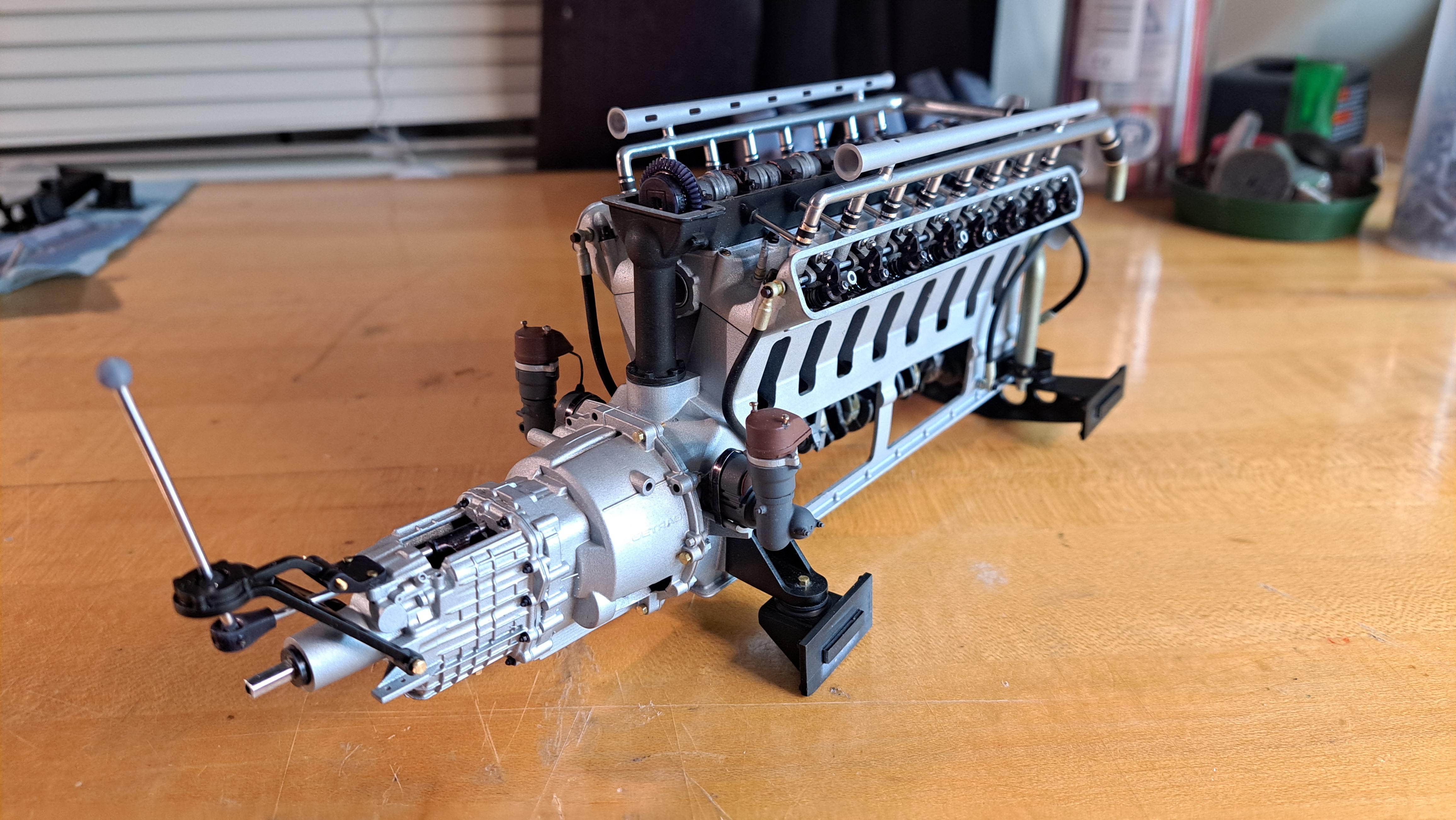
Thank you everyone. I was finally able to drive everything from the gearmotor hidden in the blower. From the blower spinning dome to the 4 rear wheels. I small victory for me! 20250121_164637.mp4 I'm printing parts while waiting for a revell paint order I did for the frame, suspension and drive components (silk black). I decided on the body color, it will be Tamiya's gunship gray which is a blueish gray. It should look a bit like the prop car made for the movie .
-
Marvel's Hydra coupe 1/12 scale full scratch build
François replied to François's topic in WIP: Model Cars
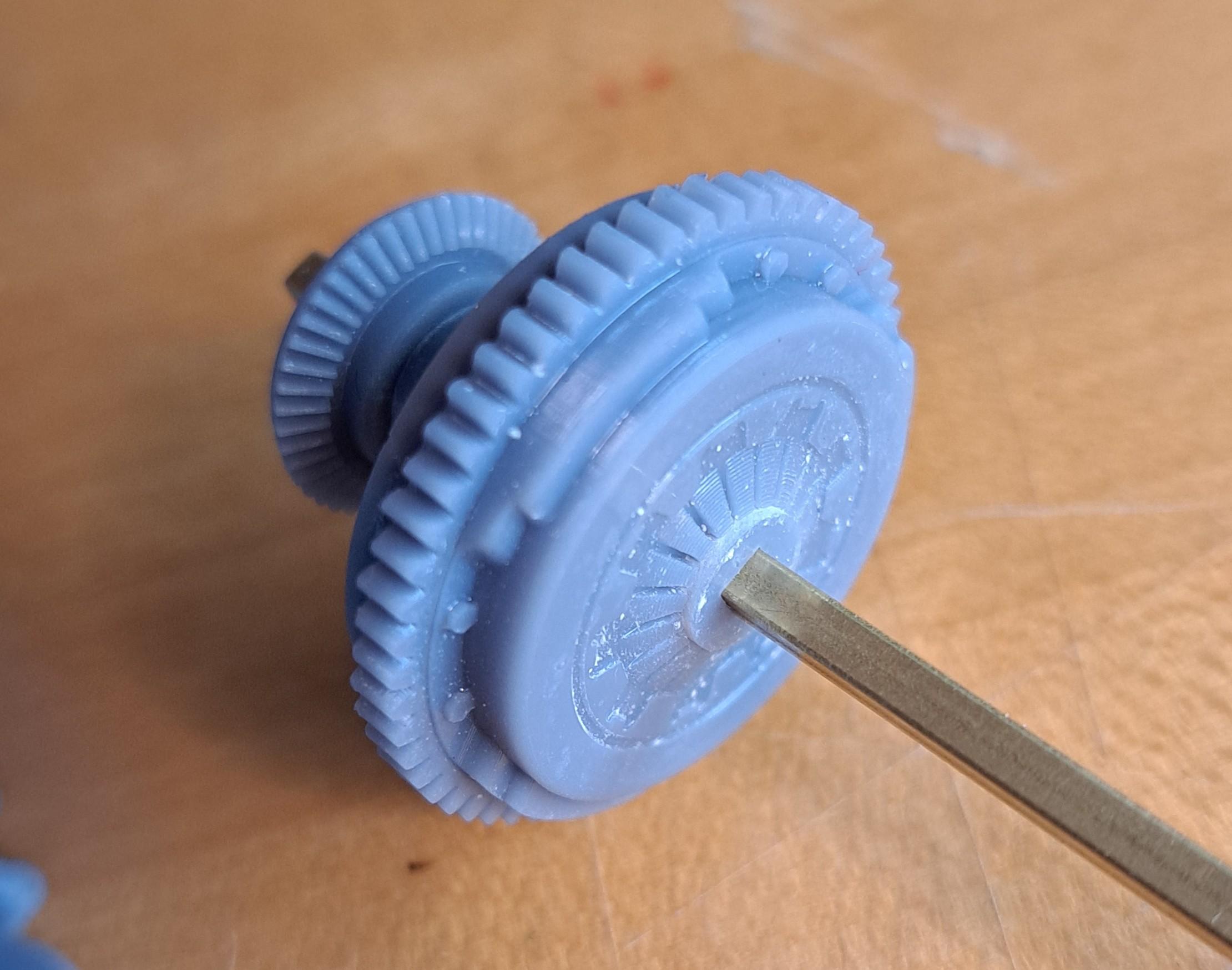
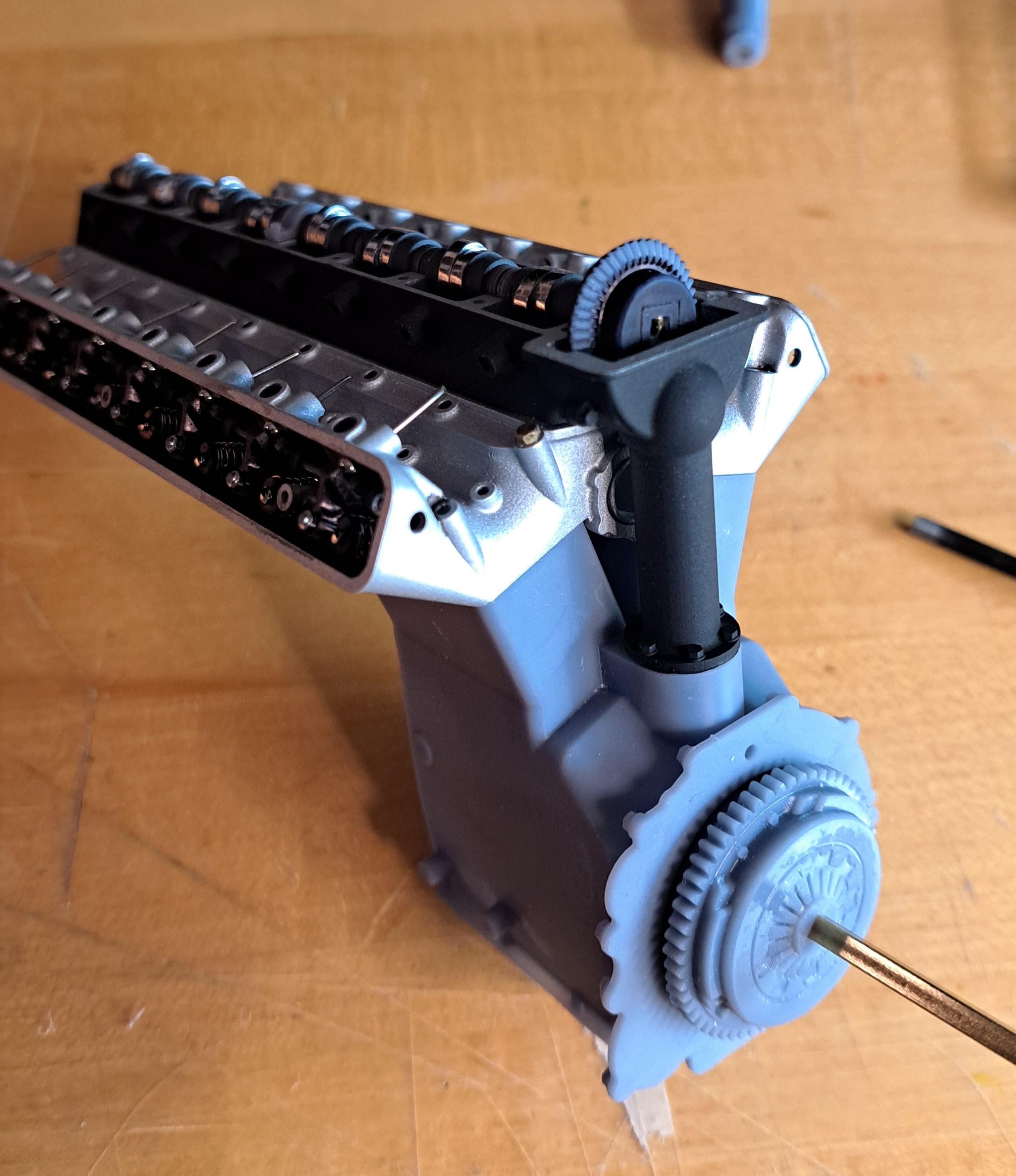
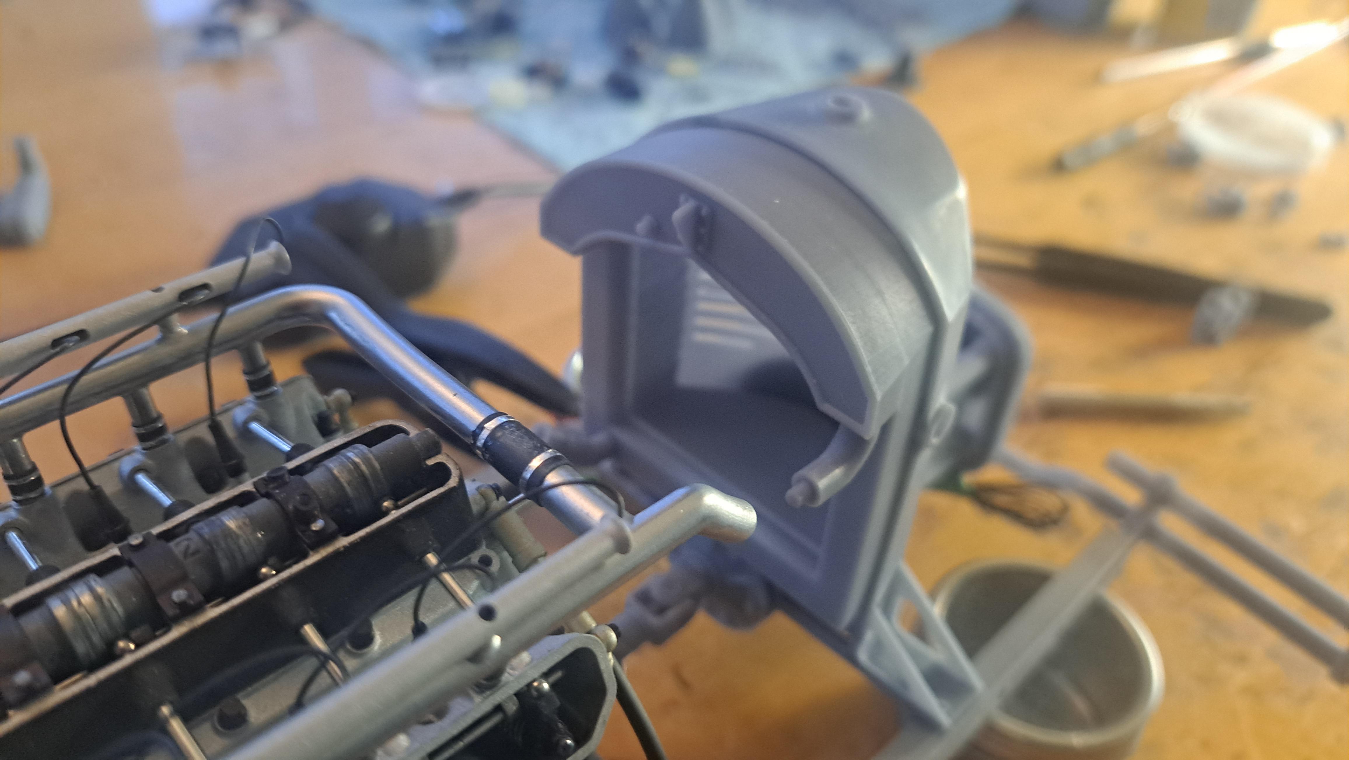
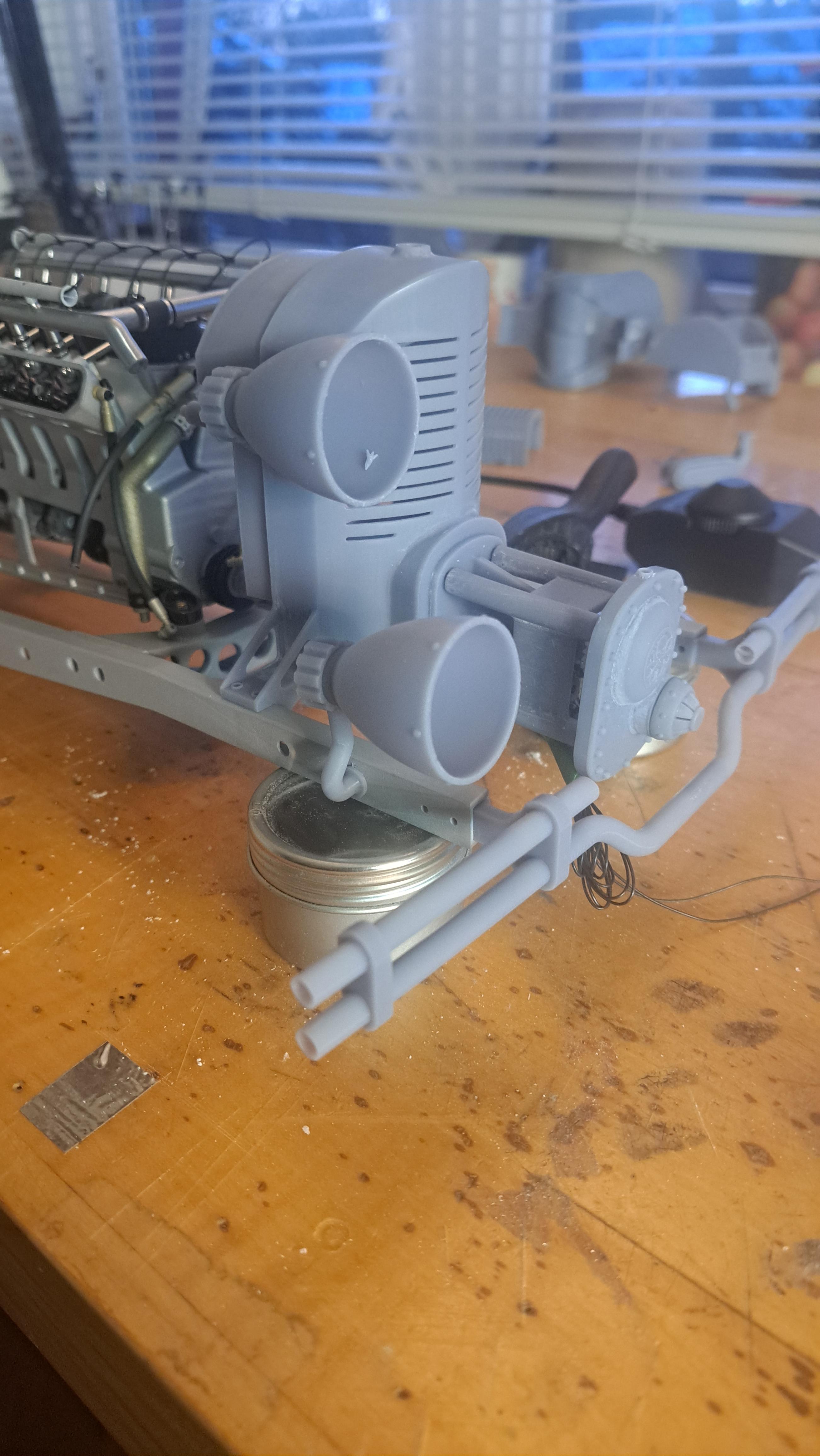
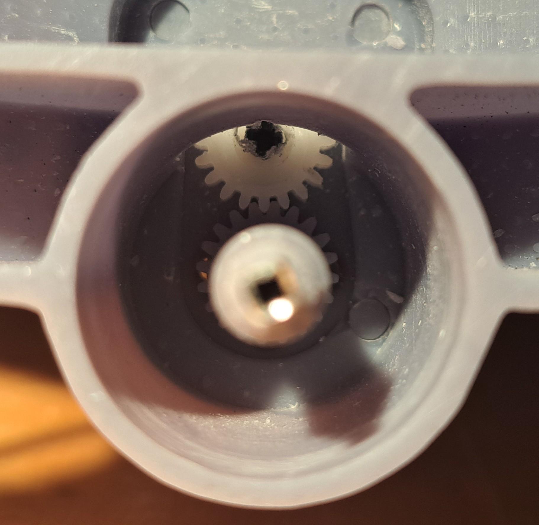
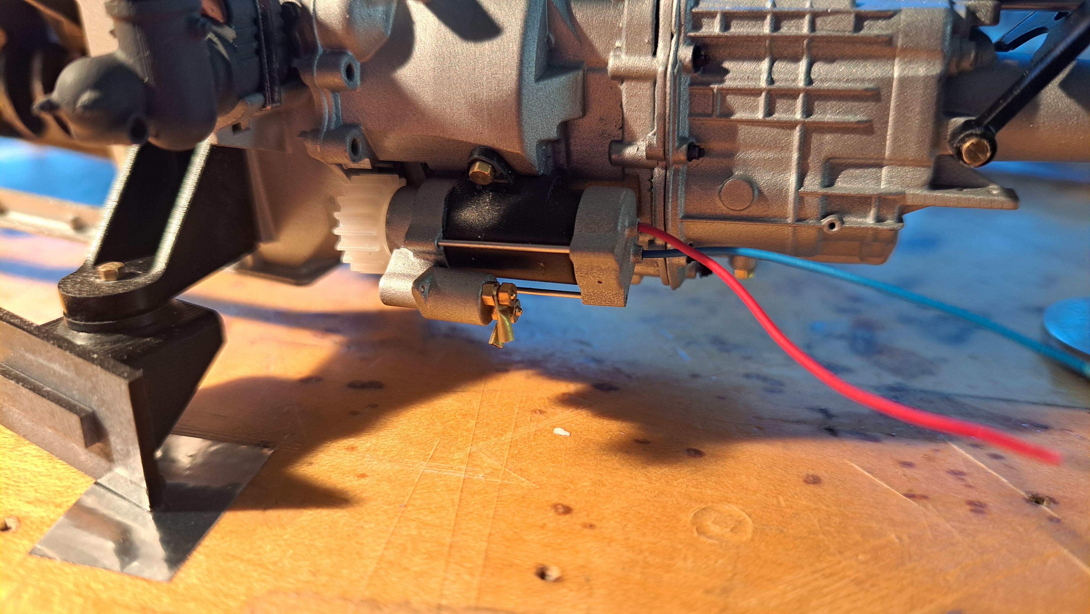
I've been more busy skiing than modeling this past week but I still managed to finalize the blower drive. I decided to add a subframe between the radiator and blower's front face to facilitate the assembly and paint. This way, I can chrome both the radiator and blower front face at the same time without having the blower housing in the way. Since the blower housing will be painted the same color as the bodywork (color to be determined), I made it in two halves that can easily be assembled later. I also made a small drive shaft between the crankshaft and the blower. If this was a real car, this shaft would drive the blower from the engine but on the model, since the gearmotor is hidden in the blower it's the other way around. Blower drive With half of the blower housing in place Small drive shaft Gearmotor spur gear (bottom) driving blower spur gear (top) Overall view of model so far
-
Marvel's Hydra coupe 1/12 scale full scratch build
François replied to François's topic in WIP: Model Cars
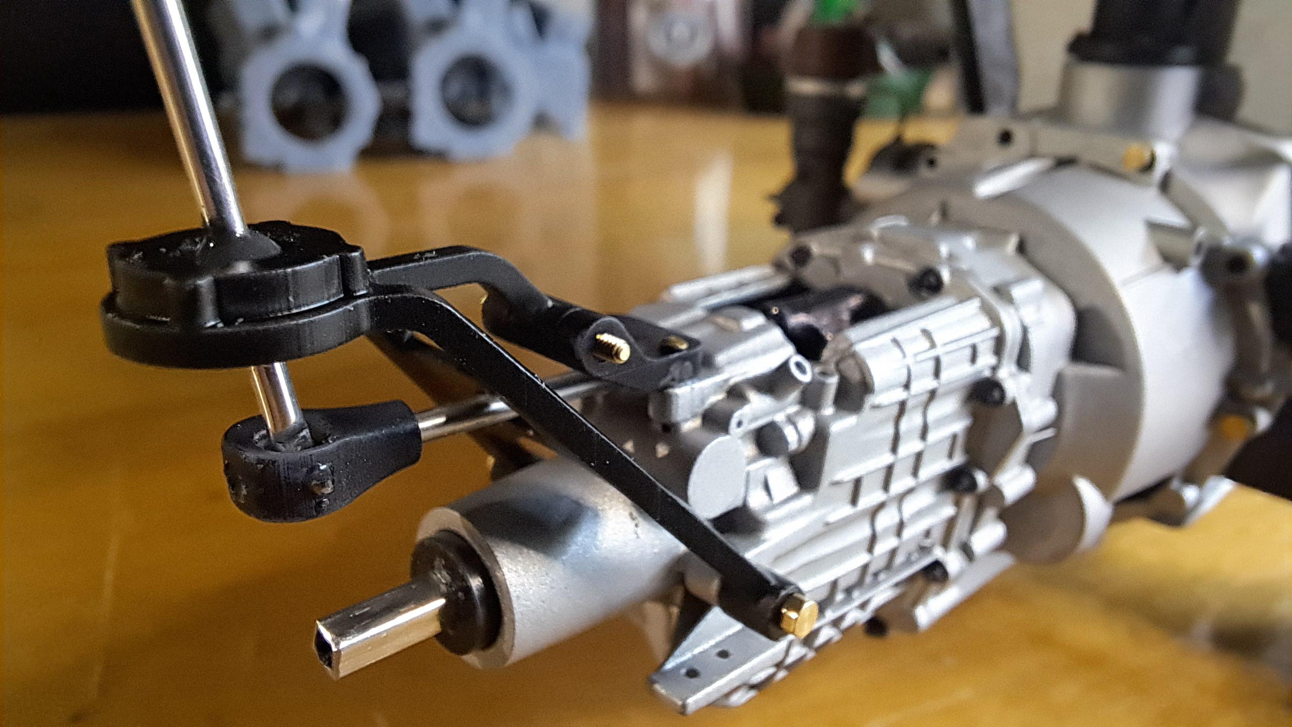
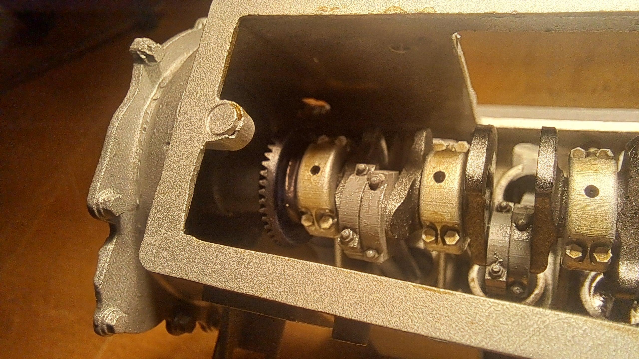
20250108_085356.mp4 I received the new gearmotor and after some tweaking and alignment issues, I got it mounted in front of the radiator, directly in line with the crankshaft. It will eventualy be hidden by the blower housing. Here's a little video showing the new gearmotor in it's new location at work rotating the car's engine and transmission. You will notice the transmission's output rotation being controlled by the shifter. 20250108_085356.mp4 But then, all hell broke loose and the crankshaft snapped! So after a complete dismantle of the lower engine (it's a vefy good thing the head assembly in bolted so it can be easily removed), I was able to replace the broken portion of the crank along with 2 connecting rods and caps. Broken crankshaft after repair being reinserted in the bloc I printed and assembled the 2 differentiels and temporarily connected them to the transmission output and was then able to drive everything from the gearmotor 20250109_175732.mp4
-
Marvel's Hydra coupe 1/12 scale full scratch build
François replied to François's topic in WIP: Model Cars
Bk9300, the frame is suprisingly stiff. The engine when bolted in adds a lot of ridigity. I'll be adding some aluminium stiffener plates on both side that should also help. The problem I forsee is more torsionnal but the body should help a lot for this... I think. The model, once completed, will be in an enclosure of some sort so will be protected from inquisitive hands and will sit on support jacks like the Bentley. -
Marvel's Hydra coupe 1/12 scale full scratch build
François replied to François's topic in WIP: Model Cars
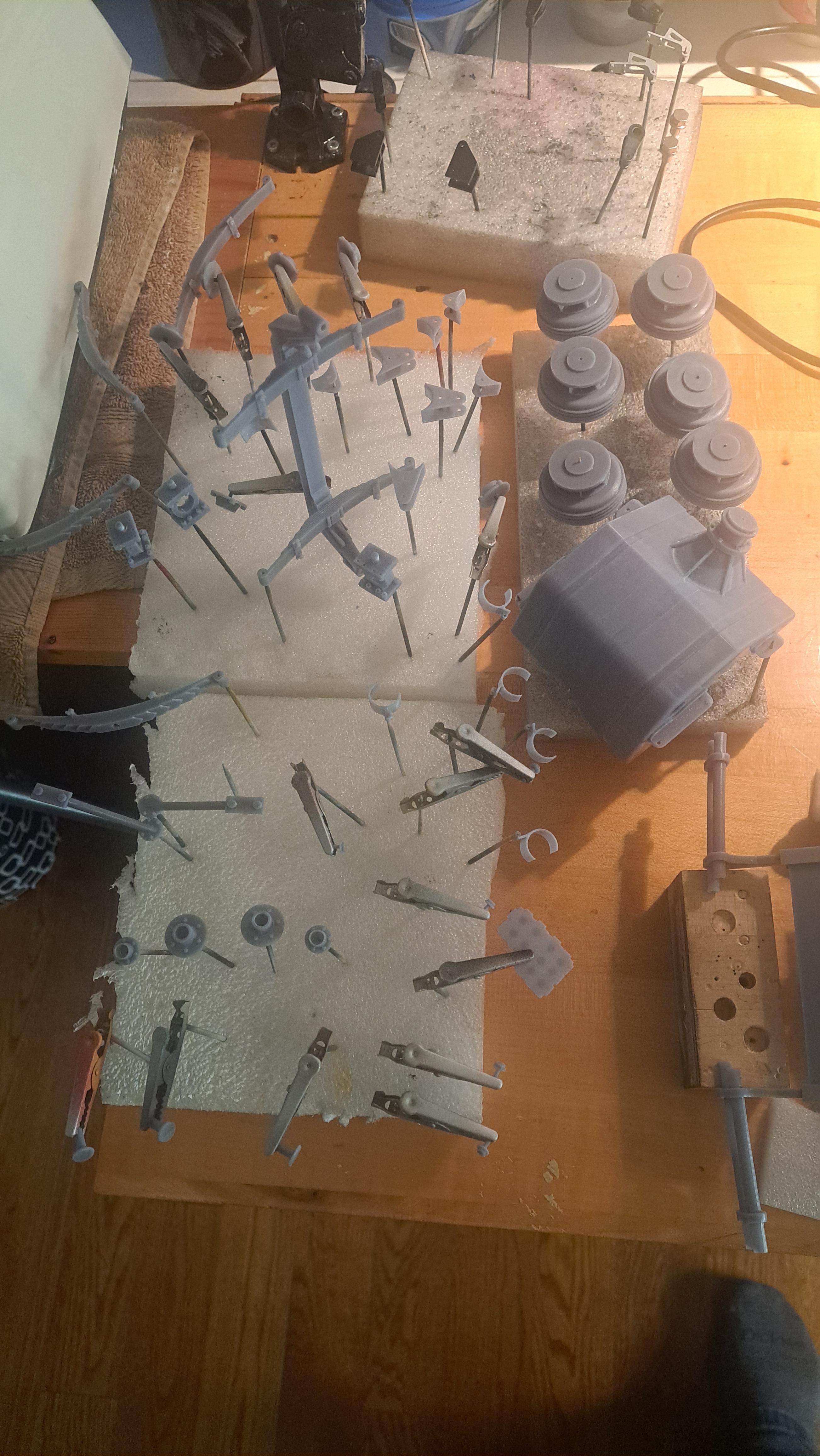
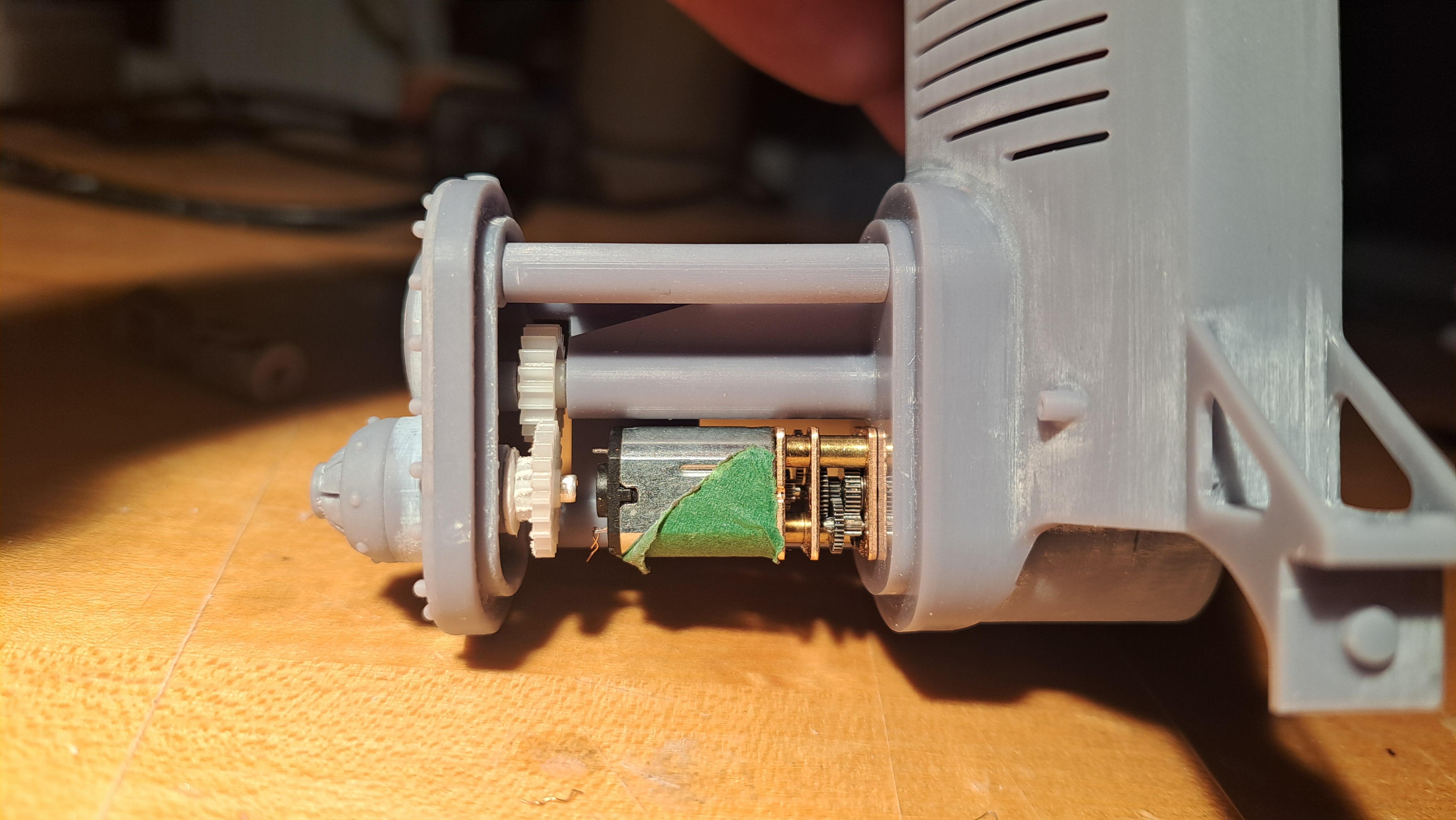
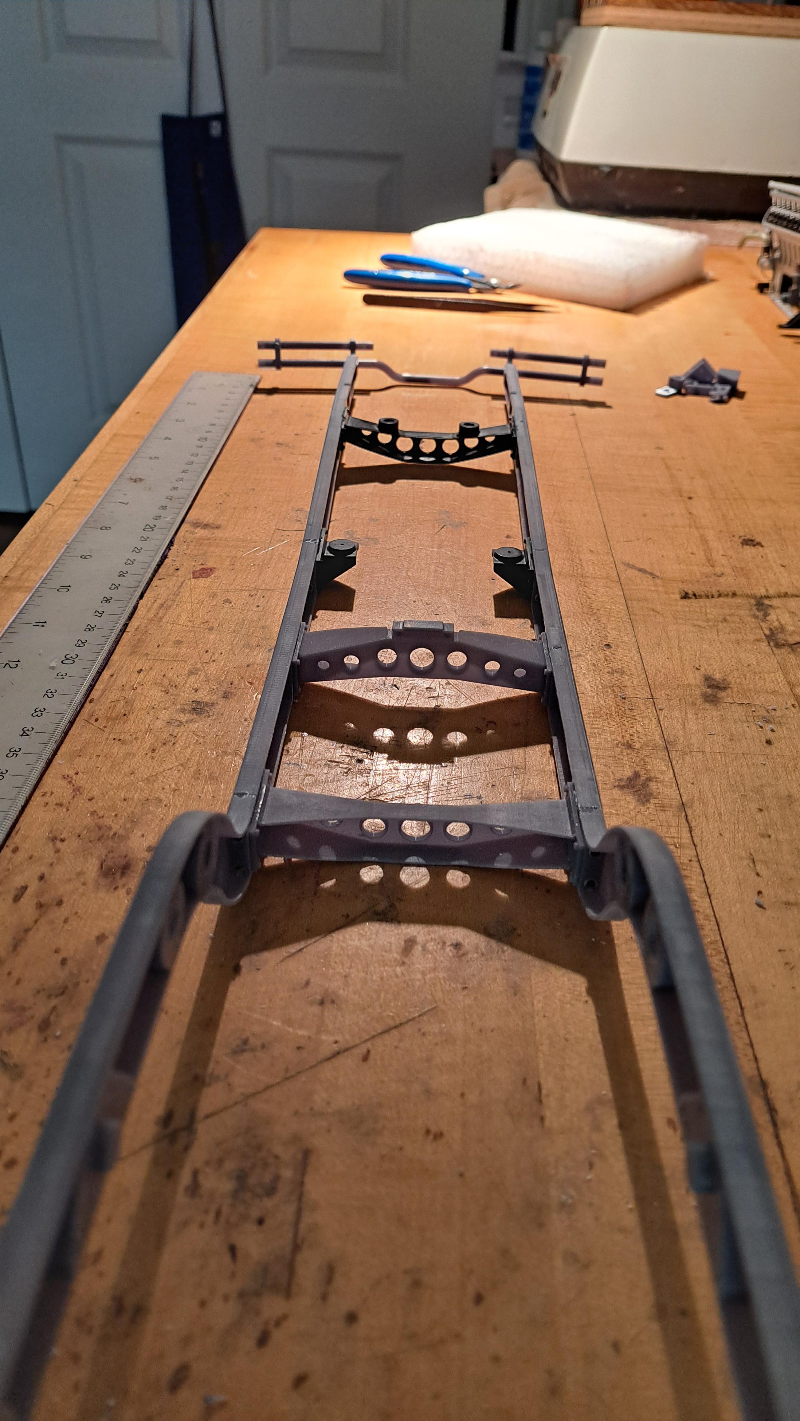
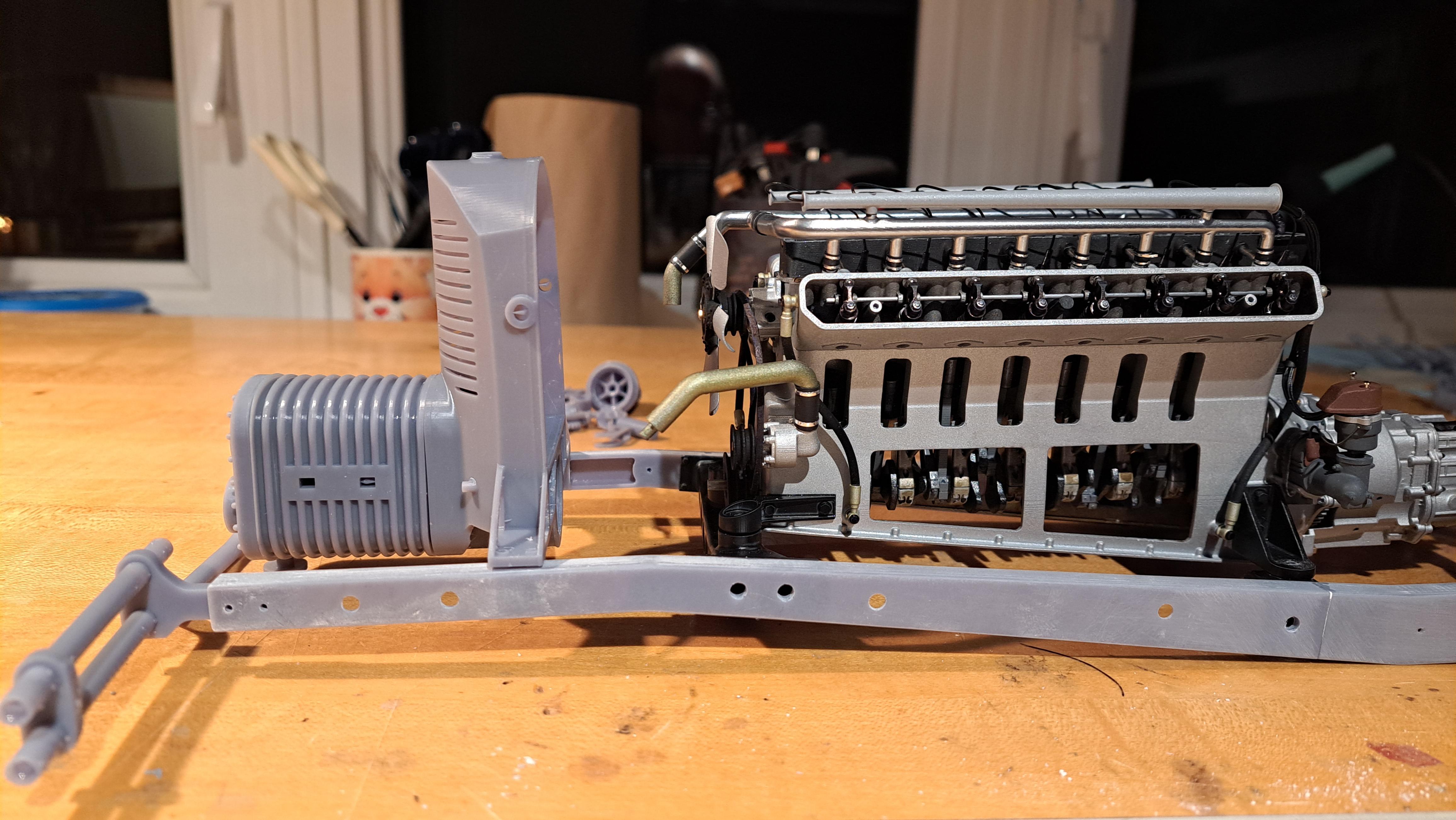
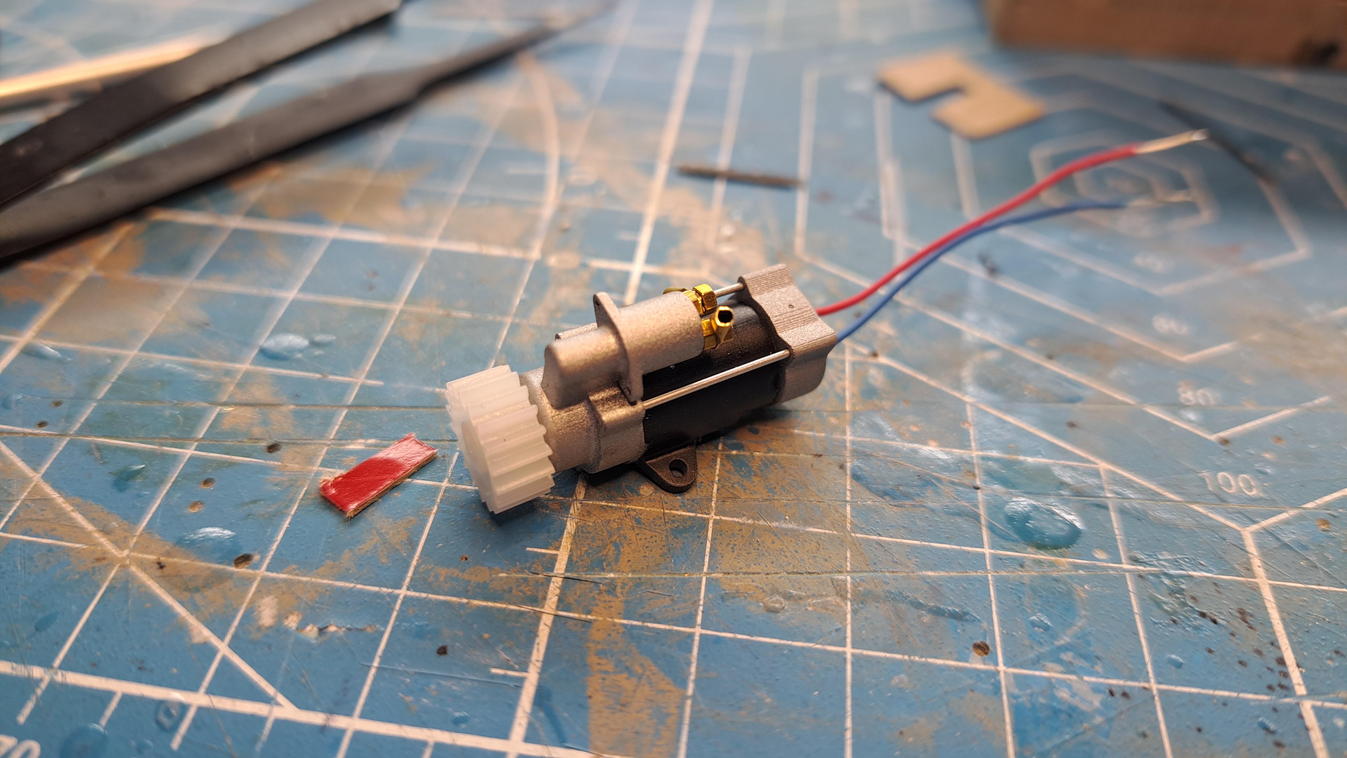
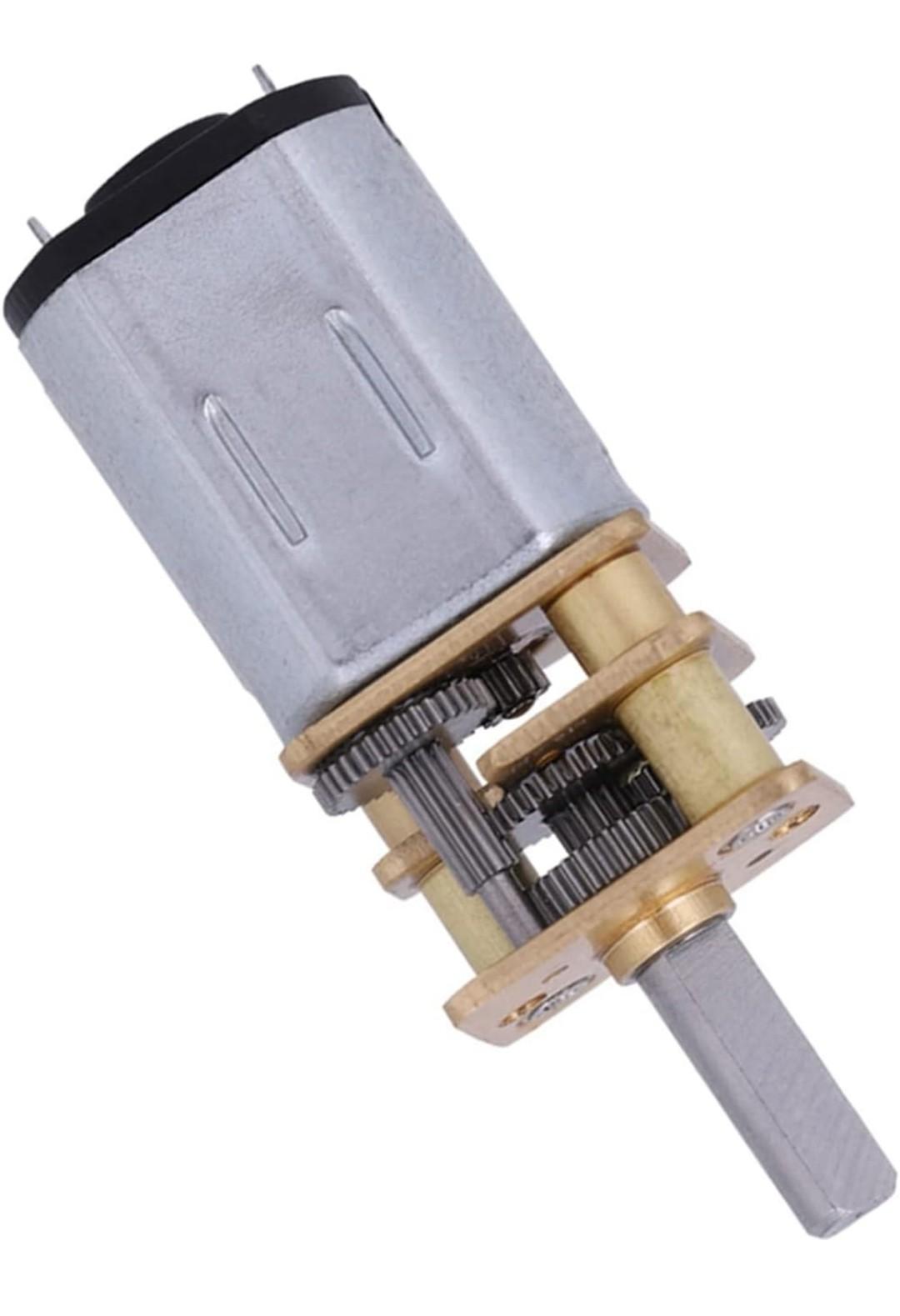
I received the 6mm dia gearmotors in 2 different ratios but unfortunately, they won't do. One simply doesn't have enough torq. As for the other, it could do but it's border line on torq and I find the rpm to slow. It's to bad because the assembly was quite nice with the gearmotor hidden inside the starter housing. I'll install the starter but it will only be for show. Here's the too small gearmotor/starter setup So I had to rethink how to drive the engine. I found another type of mini gearmotor, it has alot more torq but it's much bigger, too big to pass as a starter. Instead, the new motor will be hidden inside the blower and it will be inline with the crankshaft. I even figured out a way to drive the rotating thingy in the front of the blower using the same gears I had planned to use to drive it in the first place. I ordered 2 different torqs, hopefully one will do the job. Here's what the new design looks like And here's the new gearmotor type While waiting for the new motors to arrive, I started the frame. It's all printed and assembled, a lot easier and faster to print and assemble than the engine. I also test printed the radiator since the new gearmotor will be mounted in it. For a test print, it came out pretty good. At the risk of repeating myself, this model will be huge ! The assembled frame (that's an 18 in ruler next to it) With the engine and the gas tank I printed last summer And with the radiator cowling and blower I'm always impressed with what the printer puts out but like I said before, garbage in, garbage out. I guess I'm not giving it too much garbage !!
-
Marvel's Hydra coupe 1/12 scale full scratch build
François replied to François's topic in WIP: Model Cars
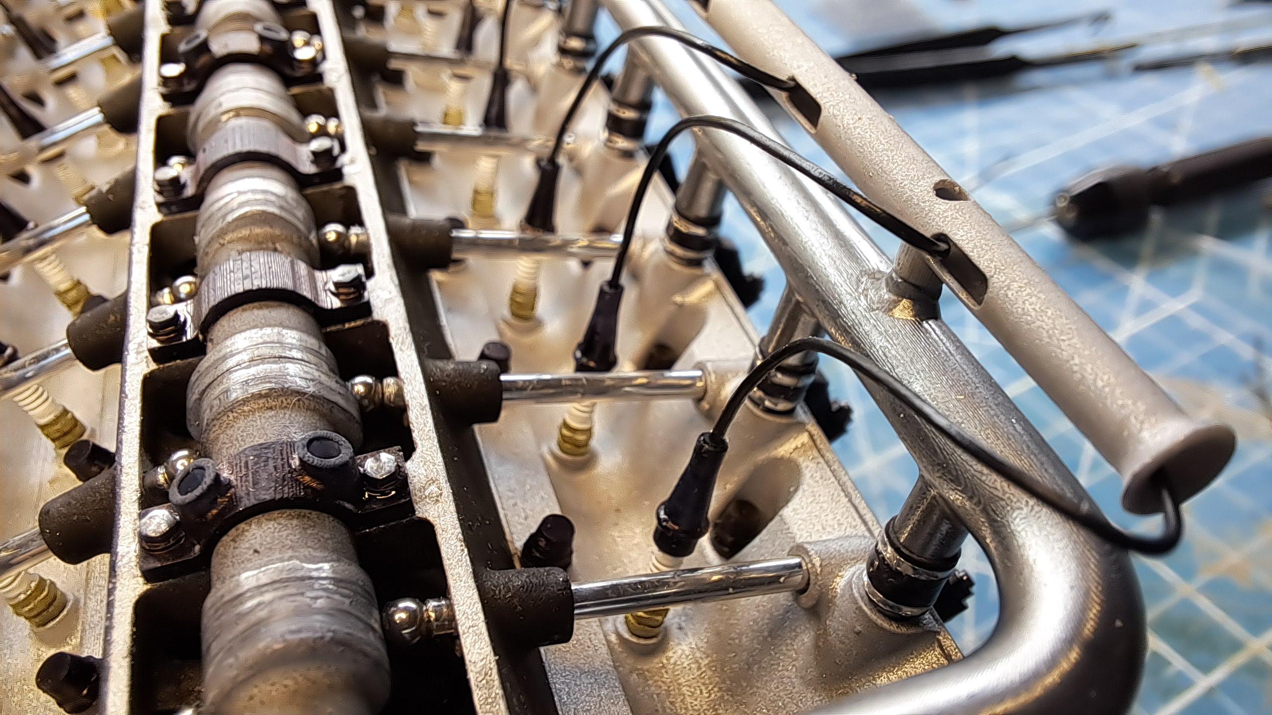
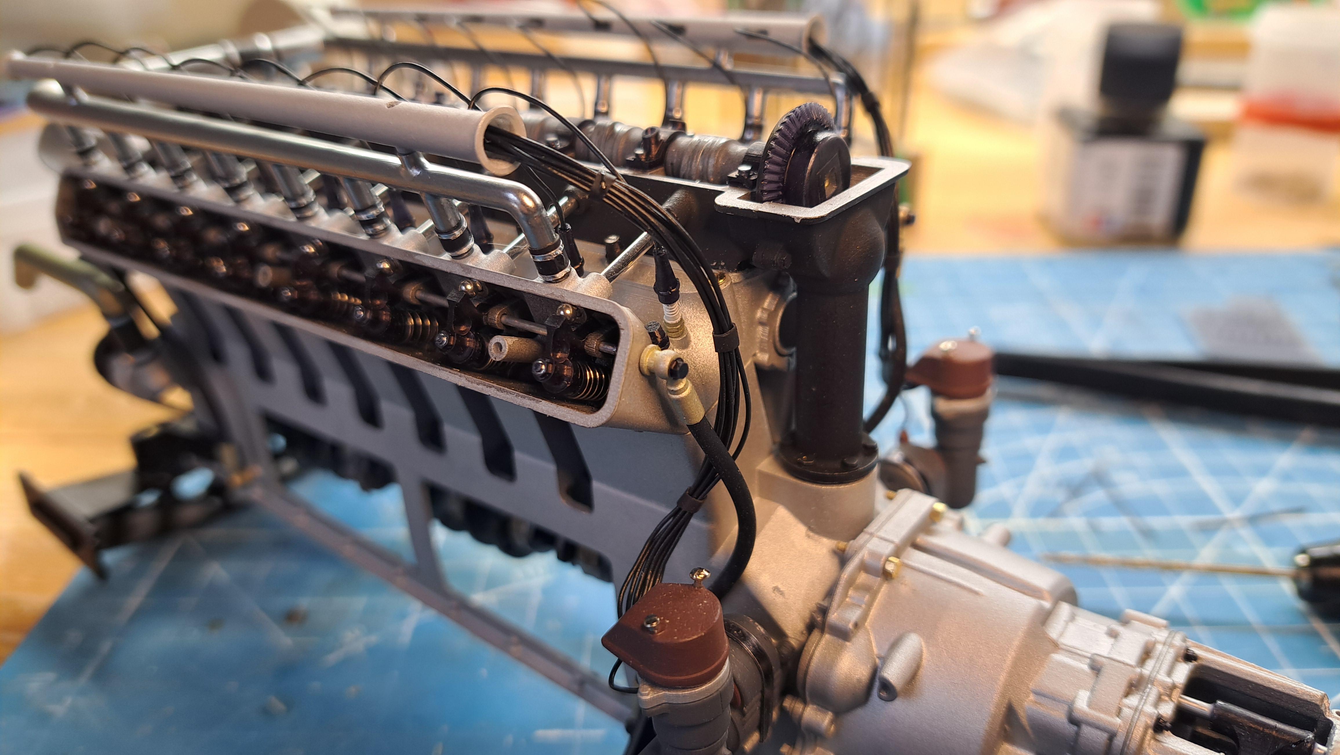
Plug wires installed
-
Marvel's Hydra coupe 1/12 scale full scratch build
François replied to François's topic in WIP: Model Cars
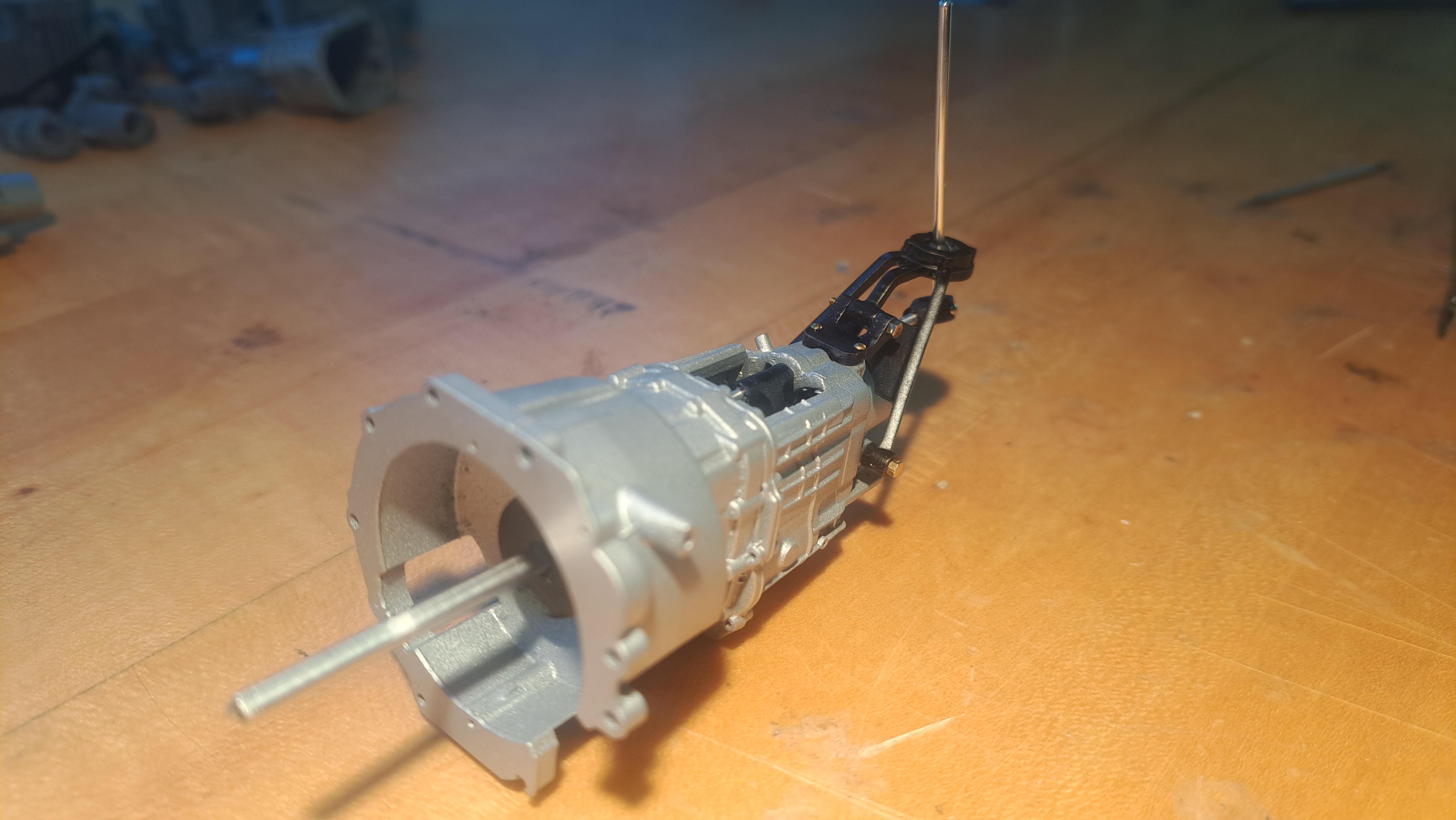
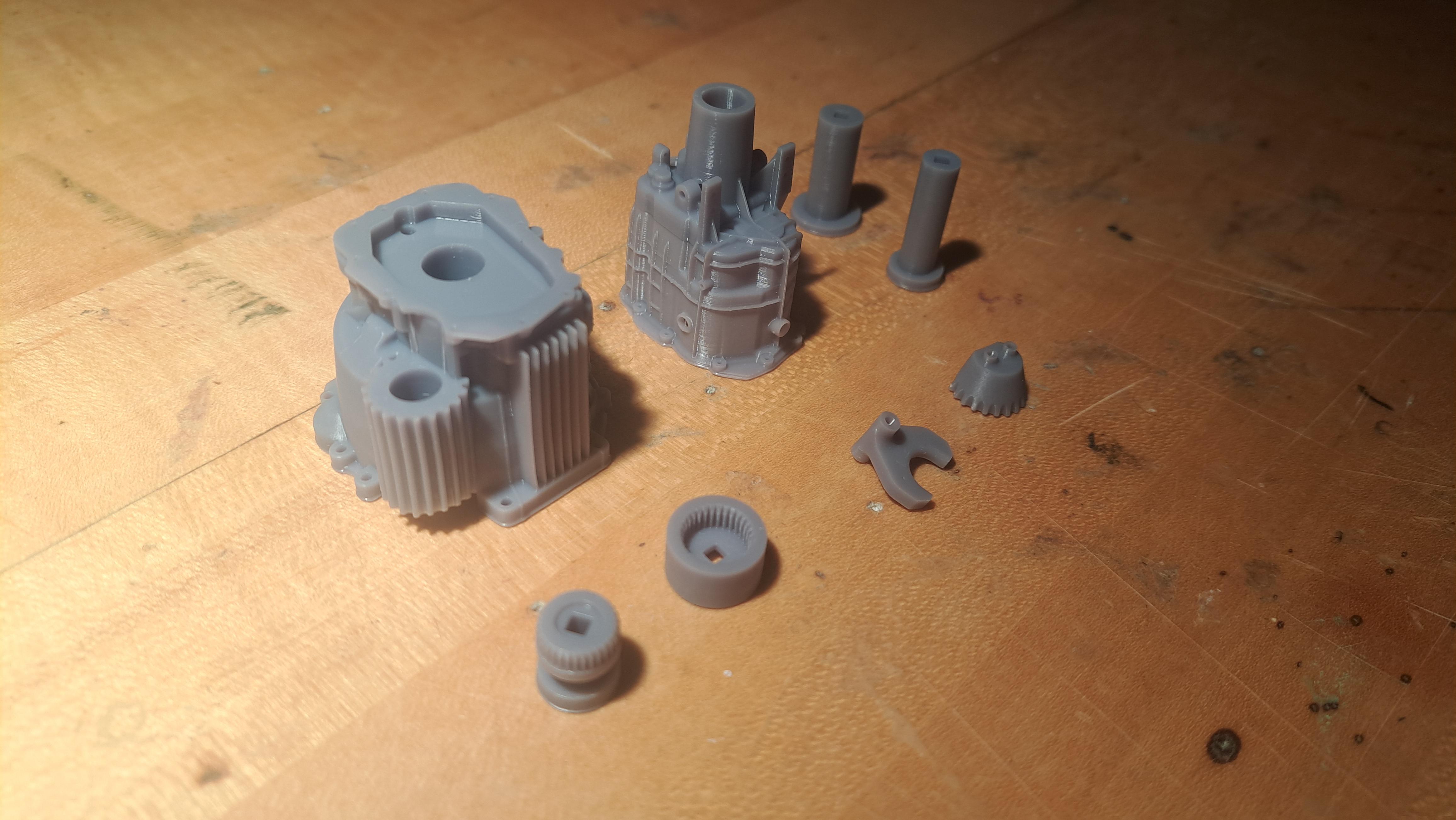
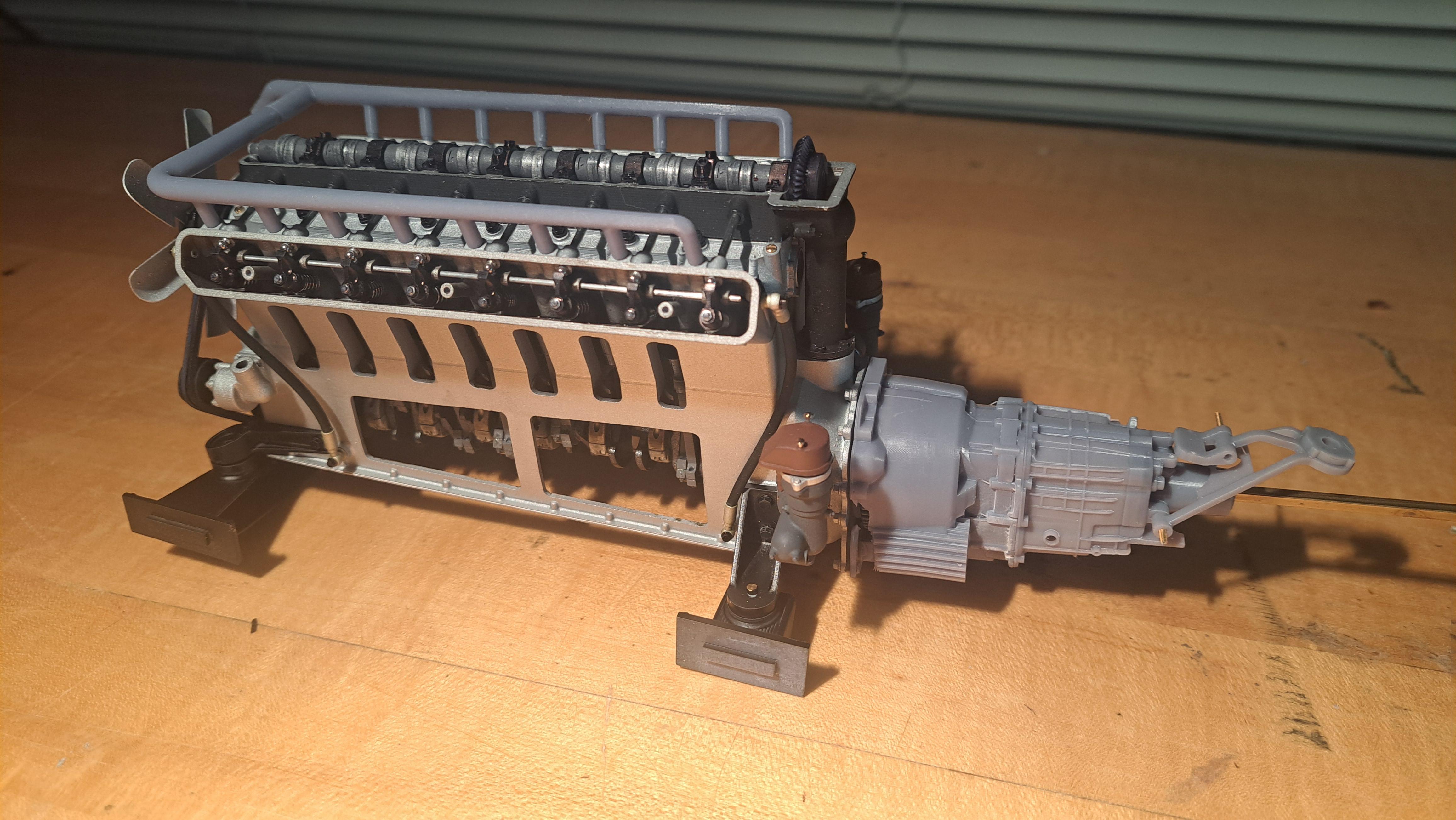
Well, the Hydra Coupe 16 cylinder engine is done and it's a beast! You might think it's out of scale for a 1/12 model but it's not. Everything is to scale. Unlike some other large scale engine out there, If you were to blow it up 12 times, this one would actually look like a very huge V16 engine. Althought I will admit I might have spaced the cylinder bores a bit more than necessary to fill the engine bay. I still need to put in the plug wires and fine tune the fit of the clutch but aside from that, it's done. The transmission is mounted and the drive/no drive mecanism works well. I've ordered a few micro gearmotors (2 different ratios). The gearmotor will be hidden inside the starter motor housing and will drive the ring gear. In the meantime, I can rotate the engine using the transmission output shaft. Here are some pictures of the transmission assembly, followed by pictures of the completed engine and a small video. All transmission parts ready for assembly The completed engine And some details Snd a small video showing the drive mecanism being engaged 20241229_205449.mp4 Next up, the frame, suspension components and front and rear ends.
-
Marvel's Hydra coupe 1/12 scale full scratch build
François replied to François's topic in WIP: Model Cars
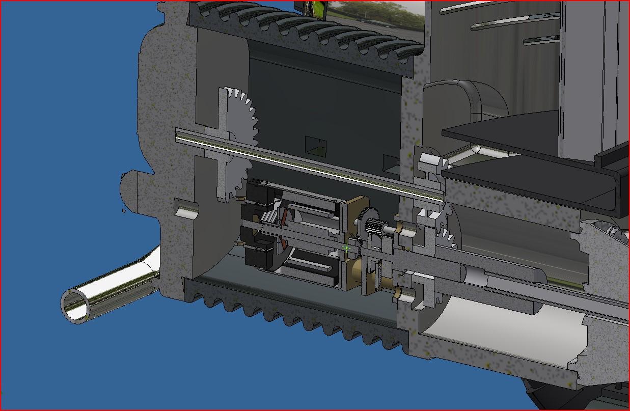
Now that the engine is done, I started on the transmission. And, naturally, I had to complicate things. I thought it could be fun to have the choice of running the engine with or without the rear wheels turning. Do to that, I incorporated a sliding gear mecanism that will be actuated be the shifter. Here's a little video showing how the thing will work. 20241224_203654.mp4 And a cross section of the engine with the transmission in place the printed parts And mounted on the engine just to see what it will look like That's it for now Merry Christmas !!
-
Marvel's Hydra coupe 1/12 scale full scratch build
François replied to François's topic in WIP: Model Cars
John, the stroke is 10.9mm (131mm scale up) compared to the 75mm stroke on the engine I based my design on. It had a top rpm around 4500. I would definatly not try my engine at that rpm. In the video, I used my dewalt drill at the low speed setting which has a top rpm of 600. I ran it at maybe half that? It's all plastic with a little bit of light oil for lub, so I won't be trying to run it any faster. -
Marvel's Hydra coupe 1/12 scale full scratch build
François replied to François's topic in WIP: Model Cars
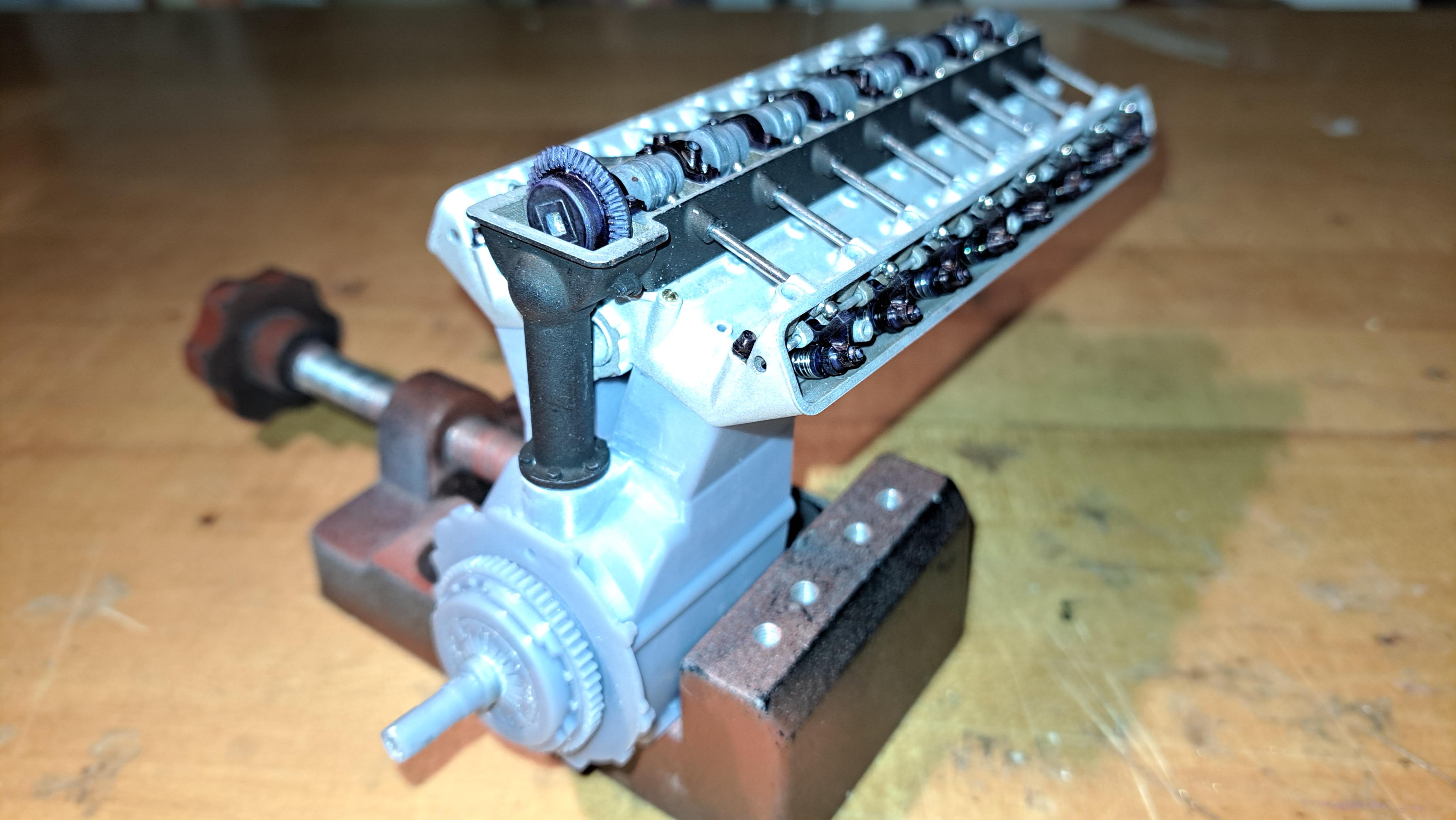
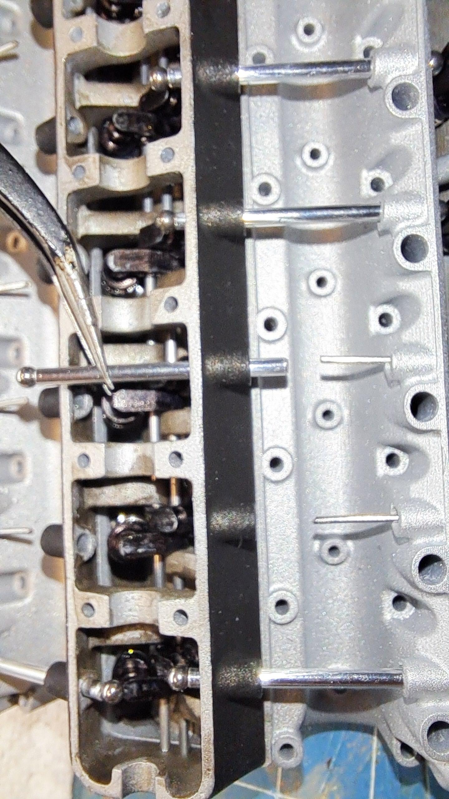
Ok so, I have many goals on this build. One was to have a working V16 engine and valve train that would drive the rear wheels. So far, as you're seen in my earlier post, the valve train is done and fonctionnal. Today, I made another step towards this goal. I now have a fully fonctionnal engine. All 16 pistons move from the crank shaft while driving the camshaft. I had my doughts but I pulled it off and it works very well, with very little torq needed to move averything. It wasn't easy to assemble but considering the precision needed but everything came together without a hitch. I more than pleased!! Here are some pictures and videos, enjoy! 20241221_192038.mp4 20241221_193142.mp4
-
Marvel's Hydra coupe 1/12 scale full scratch build
François replied to François's topic in WIP: Model Cars
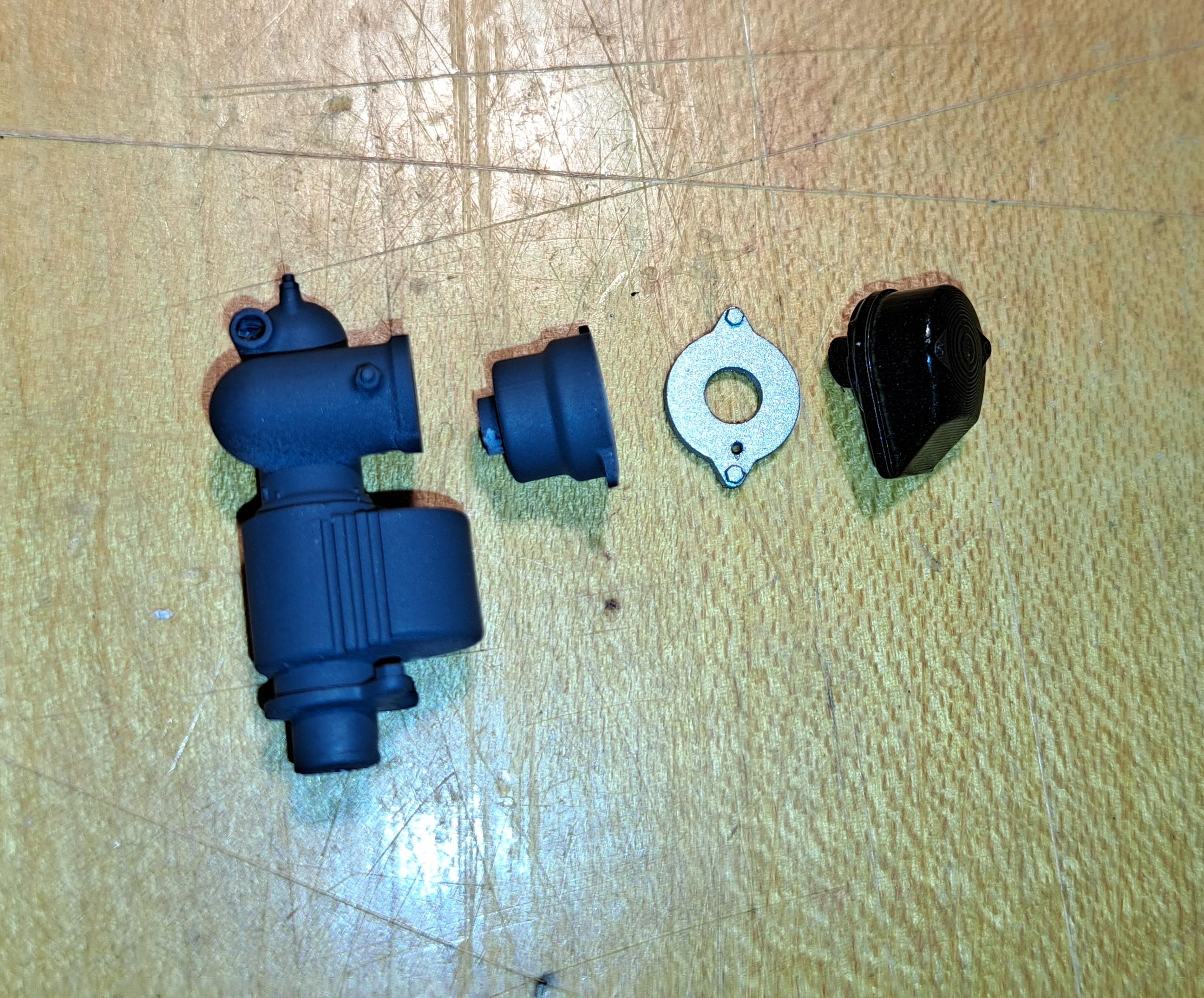
All the parts for the engine are printed (and being a V16, there's a lot of parts!) And most are painted. I still need to do a bit of weathering, a bit of oil here and there but nothing too fancy. It took me 4 tries to print the bloc but the 4th one is flawless. Here are some pictures. Lower engine components Exhaust (not painted) Distributer Water pump Fuel pump A bunch of hydraulic fittings. I painted them aluminium then applied a yellow wash to get a cadmium plating affect A spark plugs with rubber cap and wire (I'll do the cadmium effect too the lower portion of the plug) I made a sanding jig to precisely sand the end of each crank shaft segment, there are 8 segments in all glued end to end so the lenght of each part needs to be a precise dimension in order to properly fit in the engine bloc. The jig The segment in the jig before sanding And after sanding Segments before and after
-
Tigercat 880E longer 1/48 scale
François replied to François's topic in WIP: Model Trucks: Big Rigs and Heavy Equipment
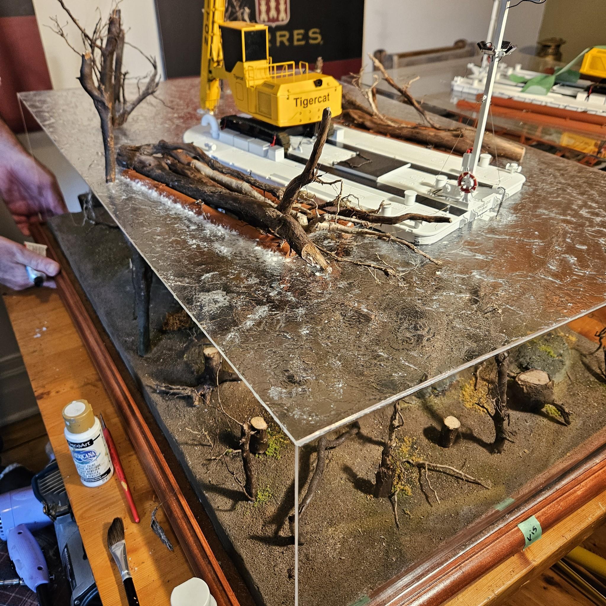
LaughingIndian, I must admit that I was very nervous even if I had seem what he does. What worried me most was when he told me 'I never did anything this big'. All in all I'm satisfied with what he did althougt I find there's too many trees, it deters a bit from the prime purpose of the build which is to showcase the harvester and the barge. -
Marvel's Hydra coupe 1/12 scale full scratch build
François replied to François's topic in WIP: Model Cars
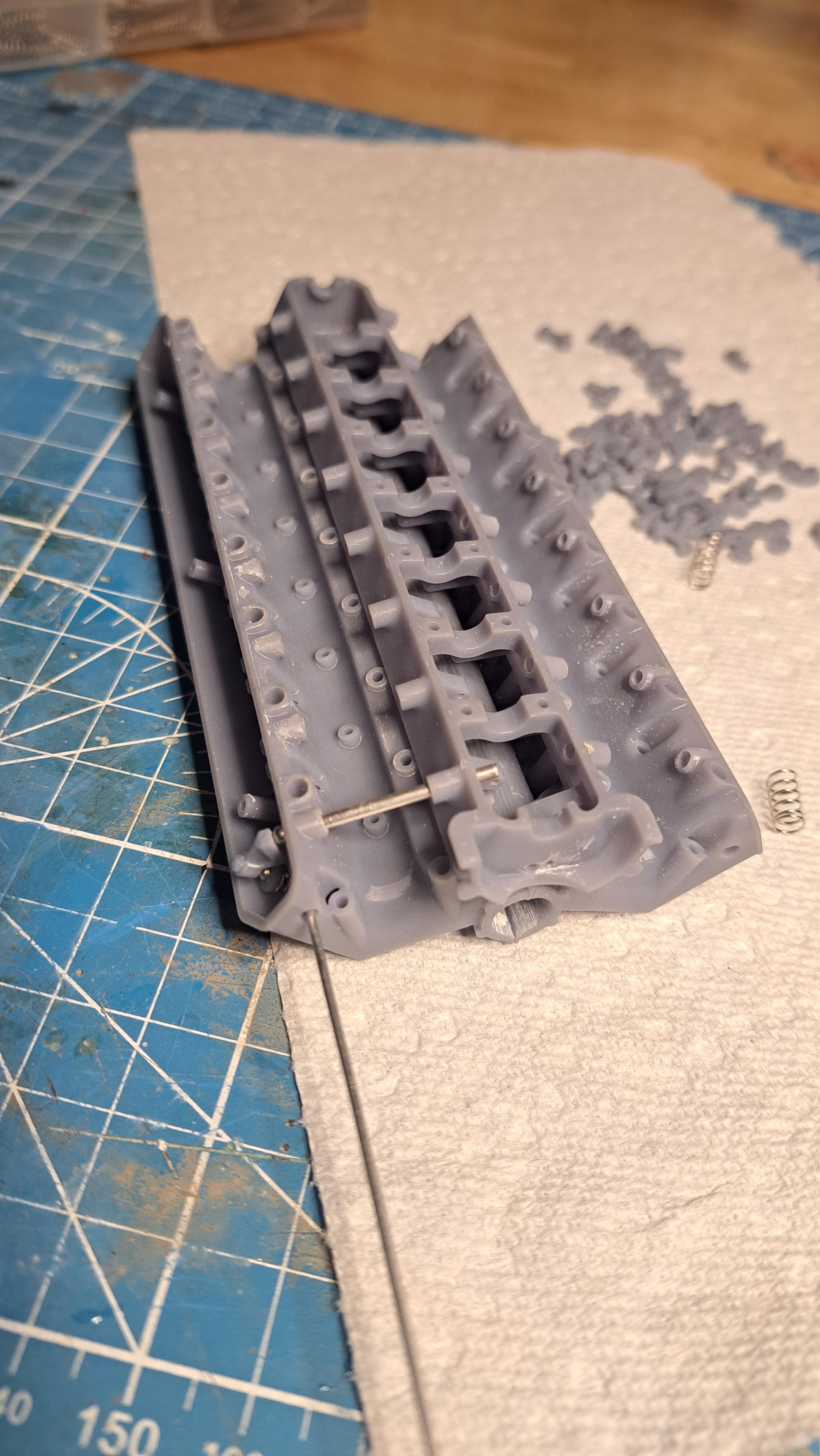
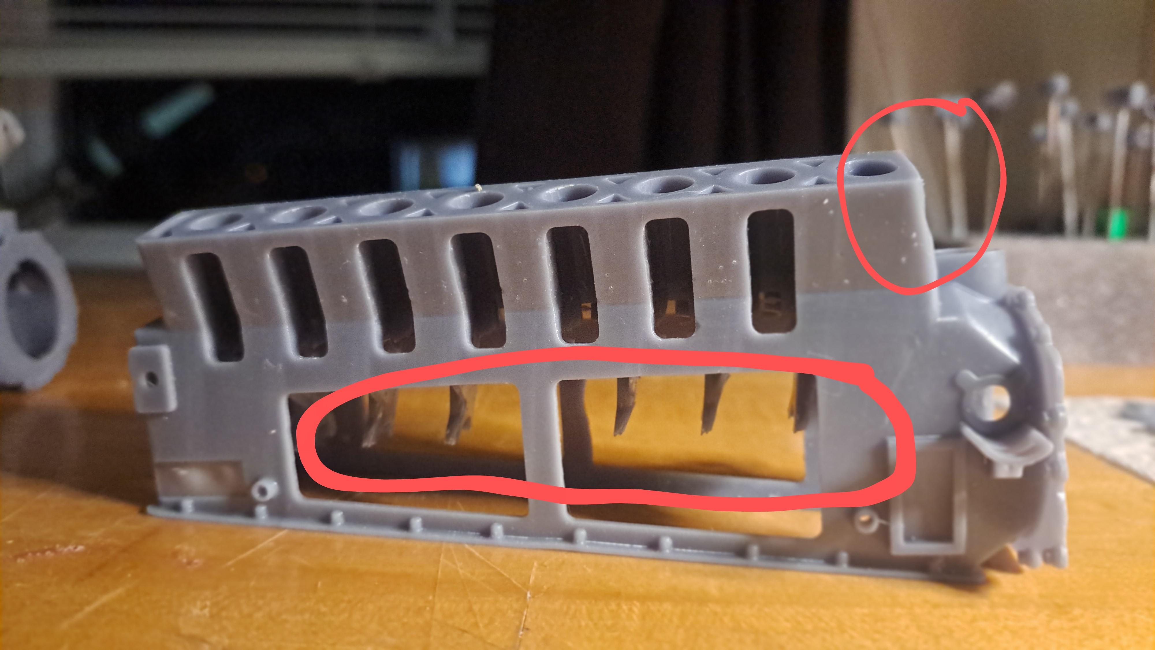
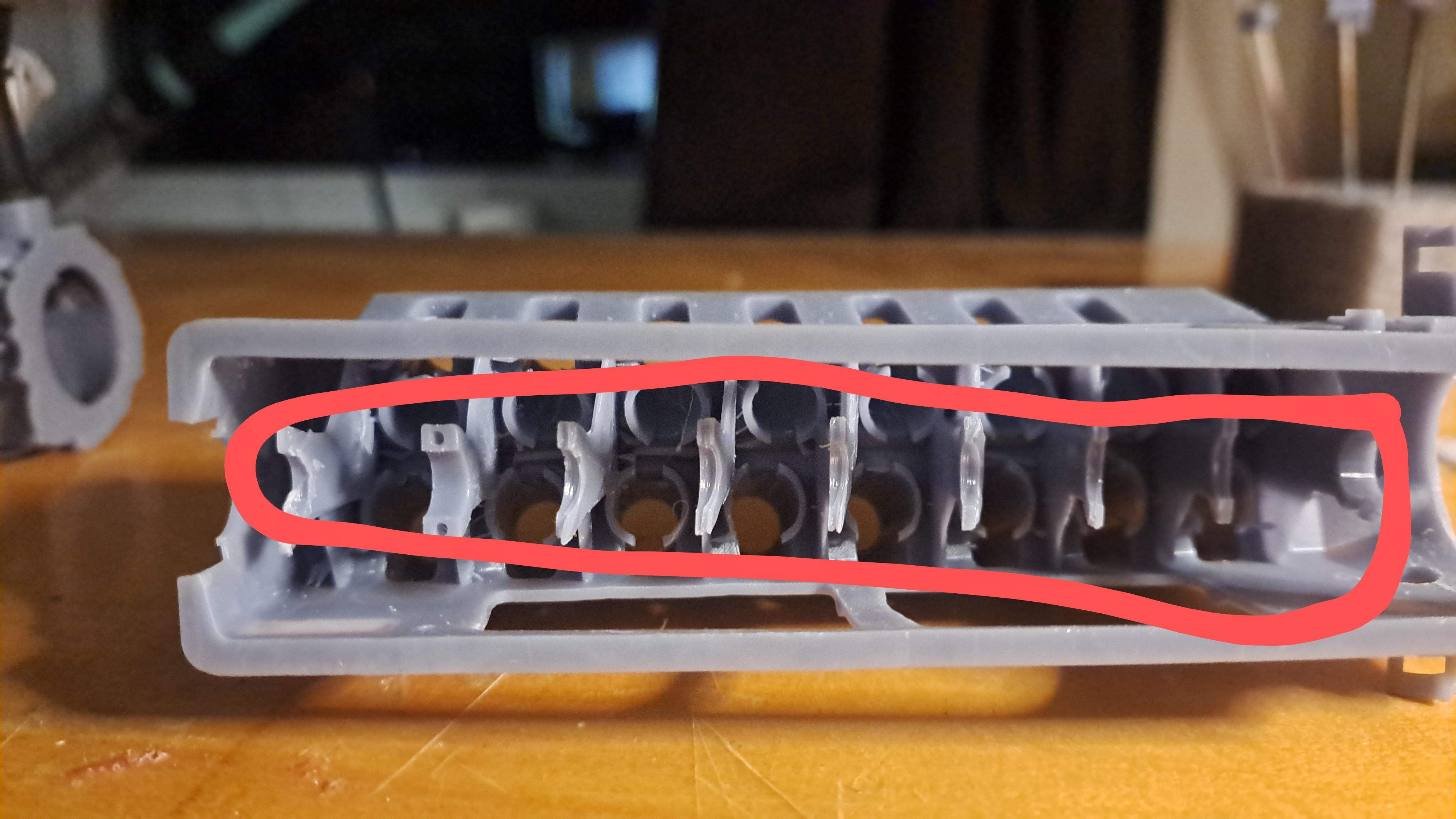
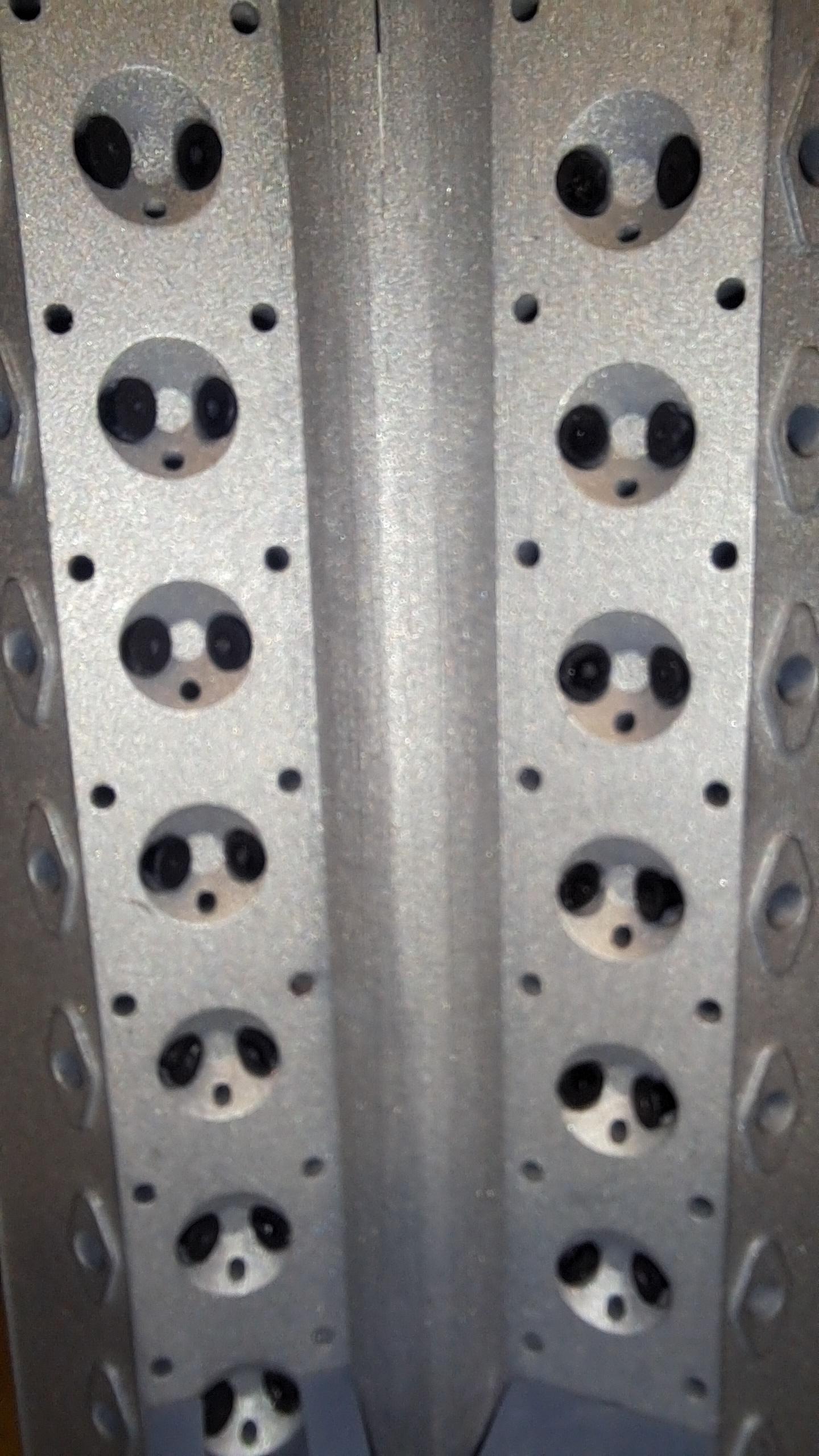
I printed the engine bloc. The first try was a partiel success (about 70% good). I printed this part in a vertical position (crank shaft axis vertical) thinking this was the best position, not so good after all. The top portion, where the head sits, wasn't totaly formed and the crank shaft support didn't print. All other features and mounting points/surfaces were ok. For the second try, I printed in a horizontal position (crank shaft axis horizontal) and I had about the same success rate. But on this one the top portion was perfect, the head sits nicely but it's the lower portion that didn't make it. The flange where the sump cover mates barely printed and the crank shaft support didn't print. For the third try, I still printed in a horizontal position but I redid the majority of the print supports. The print has just completed and is still dripping so it's hard to see but it looks promissing. First try With sump cover in place With the second try, hge head sits nicely but bottom flange is a mess Third try fresh off the printer, still dripping and full of supports but it looks good. Test print of 1 of 16 exhaust pipes, looks ok.
-
Marvel's Hydra coupe 1/12 scale full scratch build
François replied to François's topic in WIP: Model Cars
I printed a bunch of parts for the lower engine. Pistons, connecting rods, caps, crank shaft, bloc mounting brackets, distributer... the plate was almost full. Next print will be the bloc itself, oil pan and the covers for the head, all tall parts so the print will be very long.
-
Marvel's Hydra coupe 1/12 scale full scratch build
François replied to François's topic in WIP: Model Cars
By the blower as on the Bentley. The vertical pipe will be connected to the blower somehow. Mucho "modeler's leeway " on all this!! I did all 16 exhaust pipes, that was quite a job, space is very restricted at the front.
-
Marvel's Hydra coupe 1/12 scale full scratch build
François replied to François's topic in WIP: Model Cars
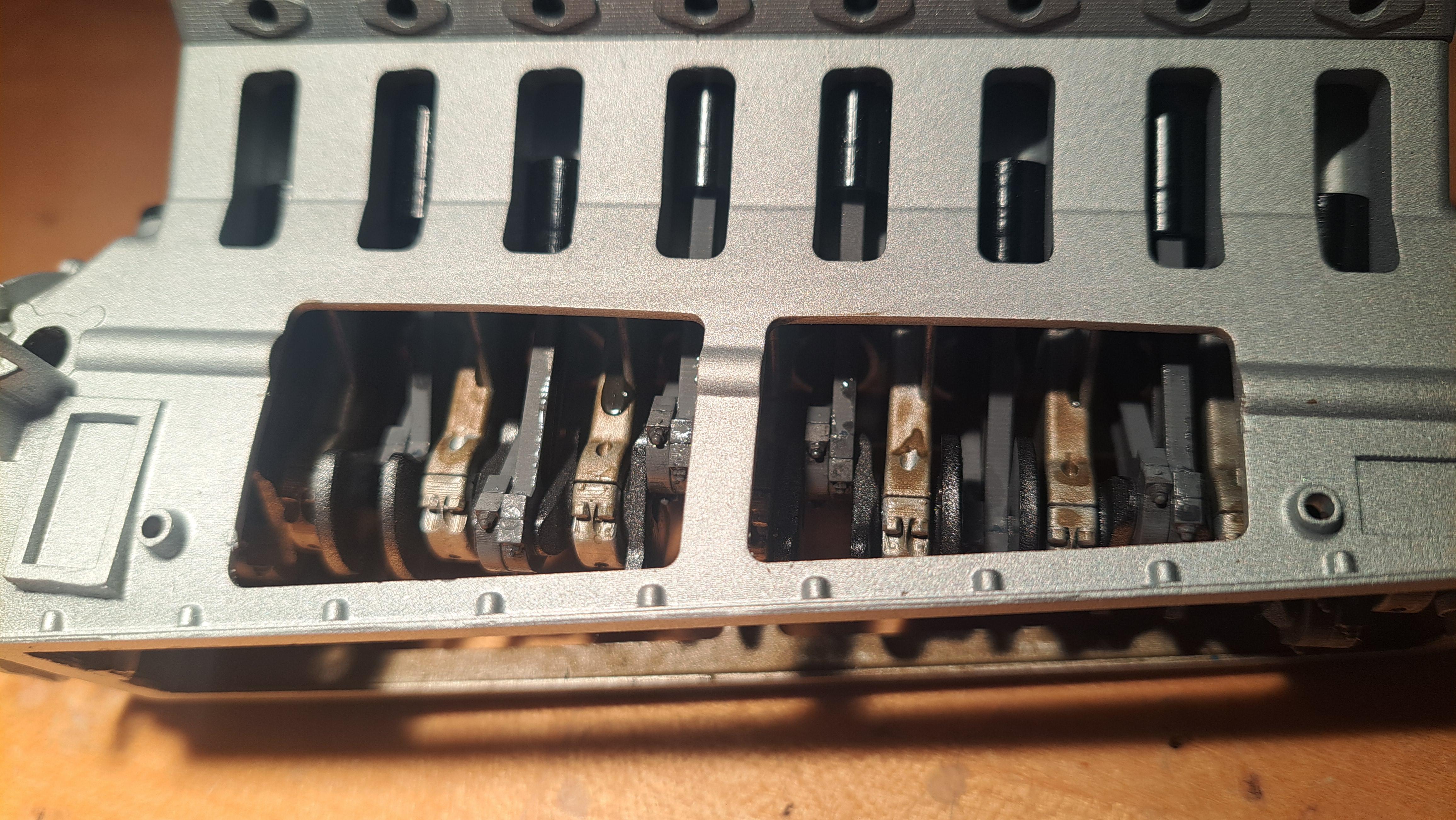
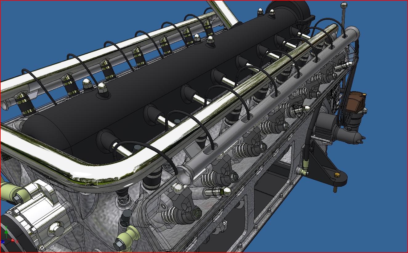
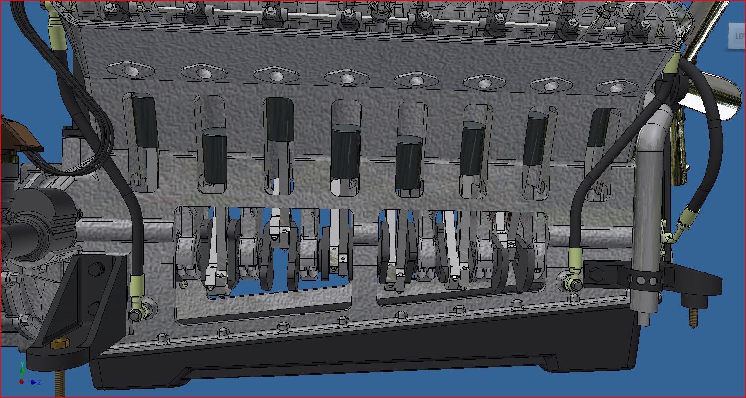
Pretty much done with the design of the engine. I incorporated some viewing windows in the block so the crank and pistons can be seen. I should start printing soon. I'll also make a base to mount it on once completed while I do the frame.
-
Tigercat 880E longer 1/48 scale
François replied to François's topic in WIP: Model Trucks: Big Rigs and Heavy Equipment
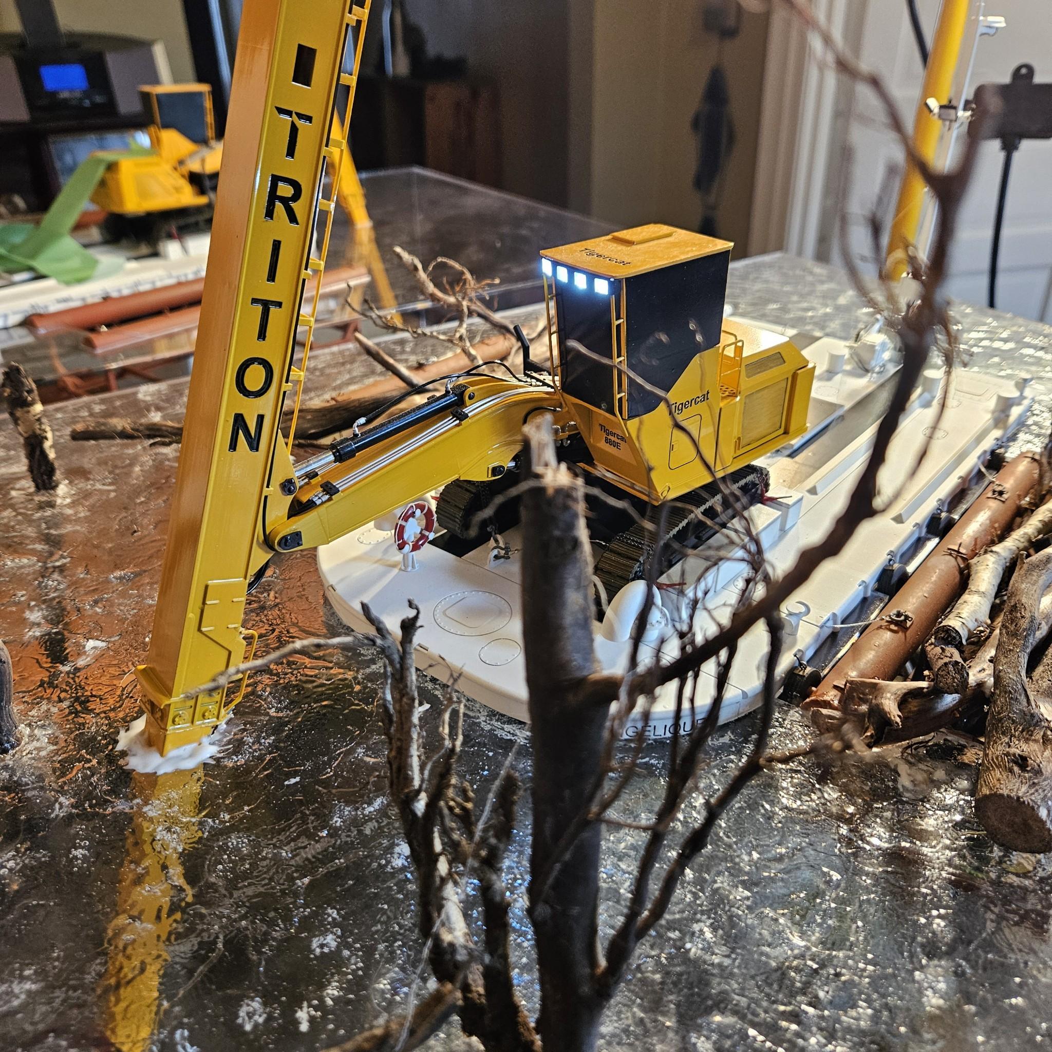
Thank you LaughingIndian, Here are a few pictures of the Tigercat and barge in the diorama (which I didn't do). It will all be coverded by a plexiglass case.
-
Marvel's Hydra coupe 1/12 scale full scratch build
François replied to François's topic in WIP: Model Cars
Did a bit more work on the motor's 3d model. Fan is in place, waterpump, cooling pipes and front motor mounts. Here are a few screen shots. Motor And motor in frame
-
Marvel's Hydra coupe 1/12 scale full scratch build
François replied to François's topic in WIP: Model Cars
Thank you everyone! I took a week off to at the beach but I'm back at it. With the head done, I'm turning my attention to all the engine peripherals, pumps, generator, fan, hoses... -
Marvel's Hydra coupe 1/12 scale full scratch build
François replied to François's topic in WIP: Model Cars
So far, the plastic did not wear. The resin I use is very hard and the groove that you see on the lobes is the chrome paint being rubbed off, there's aslo a little bit of grease that adds to the wearing effect. Naturally, this thing is not meant to be run often so I'll have to control myself because it's really fun to see those little rockers move!! -
Marvel's Hydra coupe 1/12 scale full scratch build
François replied to François's topic in WIP: Model Cars
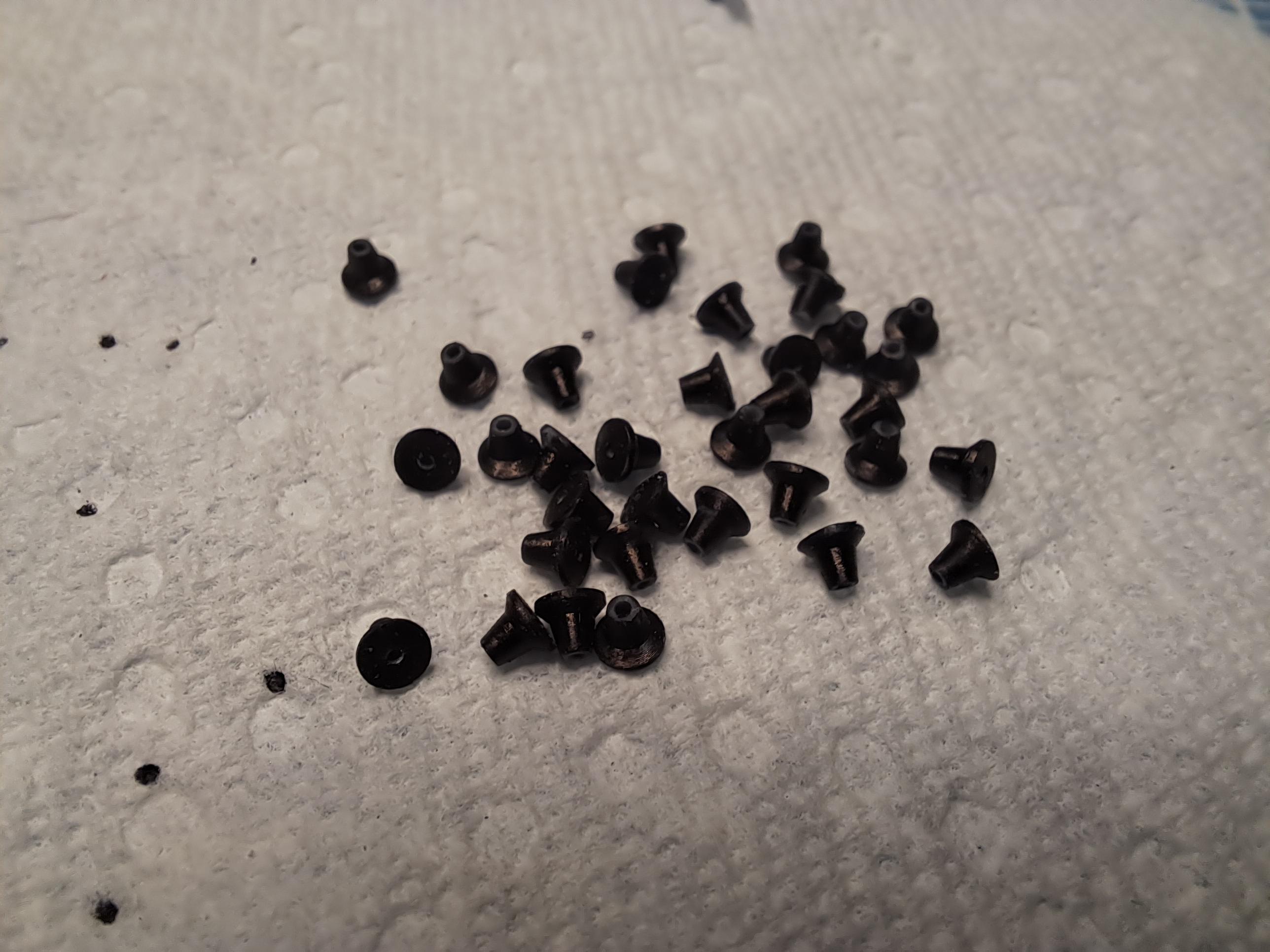
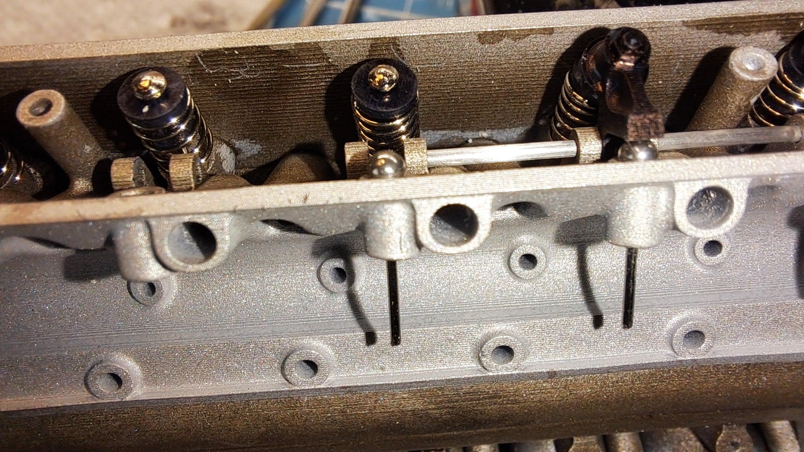
After many hours of testing, modifying, reprinting and assembly, I finally have a fully working 1/12 scale V16 engine head!! 32 valves, 32 rockers, 16 push rods, 1 camshaft and some gearing. All working together. I'm really really happy with the result. I did have to make certain modifications and compromises. I redesigned and reprinted all rockers with a different contact face to8 the valves. I also redid all valve spring washers to better guide the springs and finally, I had to shorten all valve springs because there was too much combined pressure on the camshaft to easily rotate it. The drawback to this is that some valves have very little mouvement. Old rockers and valve on top New ones on bottom Some assembly pictures Pictures of completed head And my 3d model Video of valves moving, you have to watch very carefully to see the movement 20241124_200332.mp4 And video of valve train in action (accelarated x4) 20241124_195805~2.mp4
-
Marvel's Hydra coupe 1/12 scale full scratch build
François replied to François's topic in WIP: Model Cars
Today marks another step towards a fully working engine. I printed a small portion of the engine bloc, the clutch and the crank bevel gear. The reason fot this is to see if I can rotate the camshaft by rotating the clutch. Here's how the system work. A bevel gear is mounted on the crank shaft which is directly linked to the clutch. This bevel gear rotates a vertical shaft going up to another set of bevel gears mounted on the camshaft. This is exactly the same system as found on the Bentley blower but with a few differences. First, it's a lot bigger, about twice as big. Second and most important difference is that on my Bentley model, these bevel gears rotated a simple shaft acting as the camshaft. Nothing else happens. On the hydra engine, there's an actual camshaft that, if everything goes to plan, will actuate 32 valves. Now we've seen that the valves can be actuated via the camshaft, well at least one can as seen in this little video. 20241119_133449~3.mp4 But to have a fully working engine, I need to be able to turn the camshaft by turning the clutch. So here's the bloc I printed with 2 pistons in place and the clutch And here's the test I did where I was easily able to turn the camshaft by turning the clutch. 20241122_102948.mp4 And a final picture showing the know painted camshaft housing and head bolted on the bloc. So far so good! 20241122_102948.mp4
-
Marvel's Hydra coupe 1/12 scale full scratch build
François replied to François's topic in WIP: Model Cars
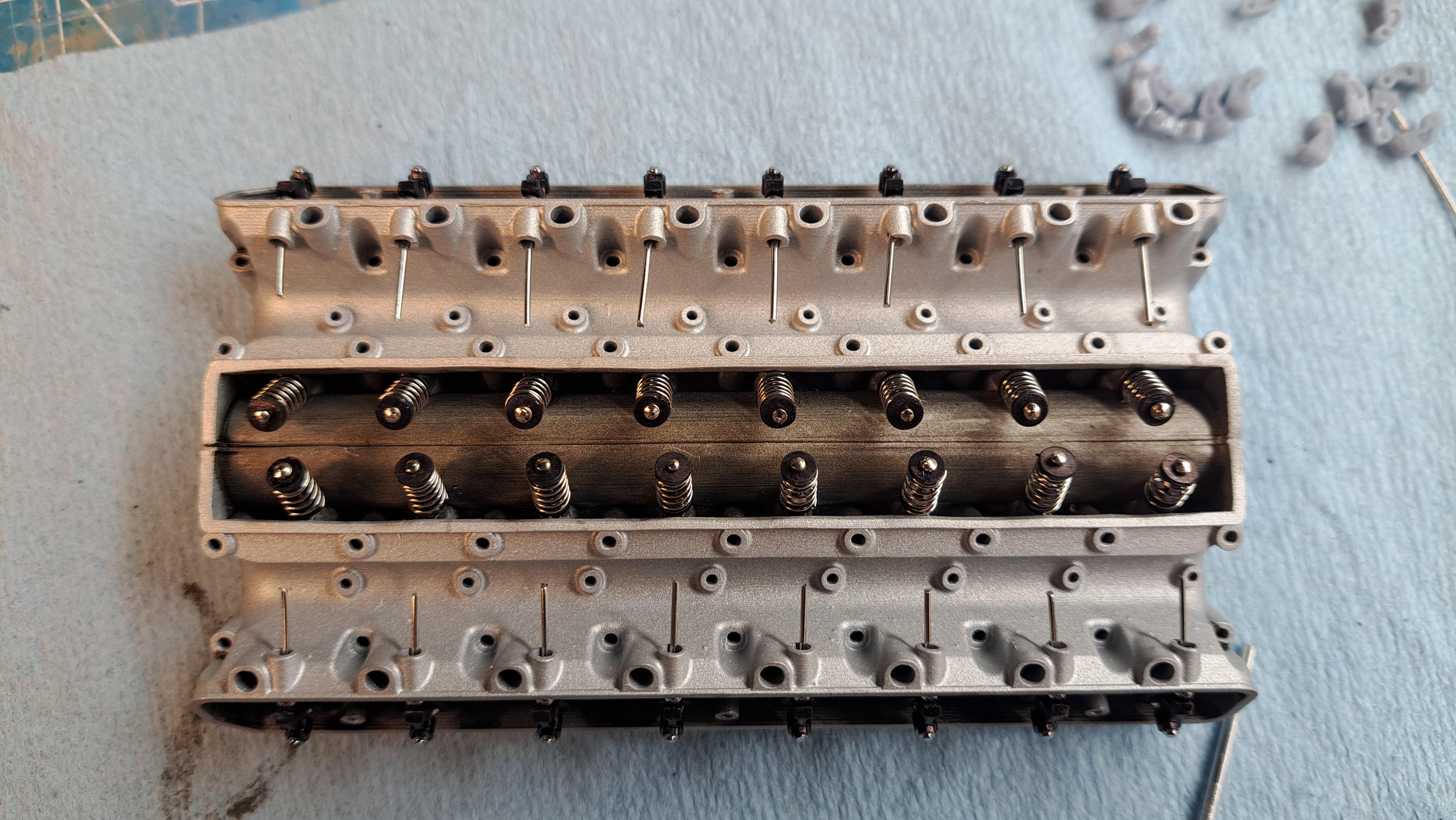
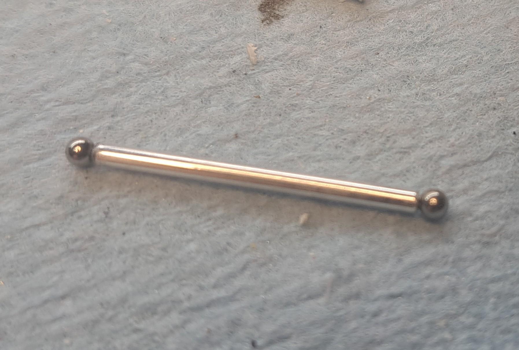
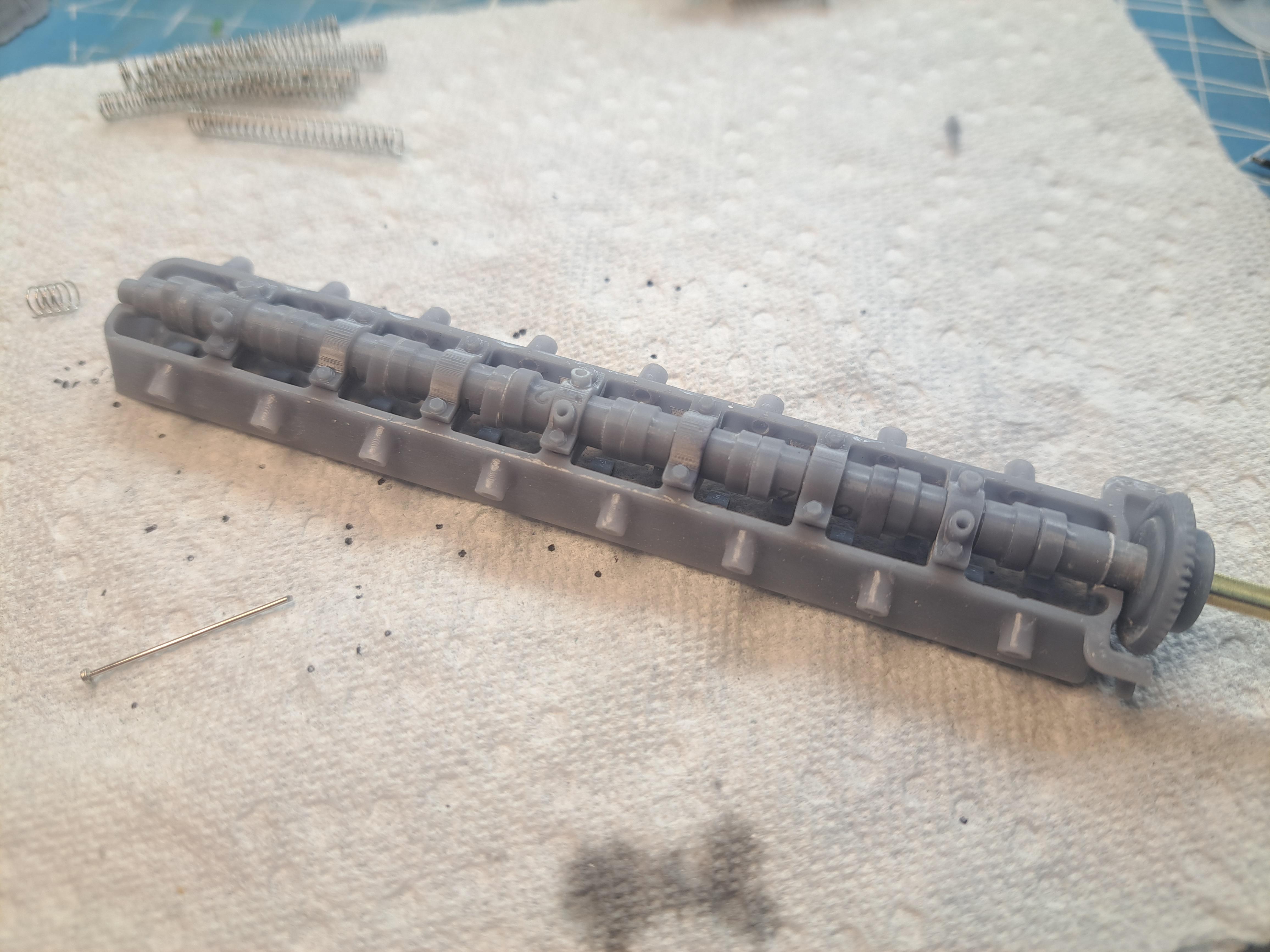
I made good progress on the head today. All 32 valves are made and in place, painted the head casting flat aluminium and added some engine grime in the concaved areas, assembled and painted the camshaft complete with simulated grounded lobe surfaces (I used a chrome pen for this) and installed the exhaust valve rockers. The black finish on the rockers is done with a permanent marker, easy to apply, close to zero thickness and dries very fast. I also made 16 aluminium push rods with spherical heads at both ends. These rods need to be exactly 1.000in long with both spheres in place, I was able to get them all within +- .002in. To make the valve stems, I used flat headed stainless steel needles that I had to cut to the correct lenght (.530in). The lenght has to be precise if I want the valves to seat correvtly. To do this, I made a simple jig using a piece of hardwood that was cut to .530in thick. I then drilled a series of .030in diaand inserted the needles. My dremel with a cutting disk made quick work of it. I also made a small jig to cut the valve springs to lenght. All valve components ready for assembly And assembled Painted camshaft head assembled Remember, this is not a kit !!
-
Marvel's Hydra coupe 1/12 scale full scratch build
François replied to François's topic in WIP: Model Cars
More work done on the engine head, I printed a boat load of small parts. I actually have 2 head castings printed, one is perfect and one has a few flaws. I'm using the flawed one as a test bench to make sure my fits are good and that what needs to move move's correctly. So I fitted a partial camshaft along with the bevel gear setup and one rocker/valve and hooked it up to my dremel and let her rip. It ran like clockwork. Here's a little video showing the rocker mouvement. I had to slow the video by 50% in order to see it move. 20241119_133449~3.mp4 And here are some pictures of the different parts printed Valves Rockers The cam shaft (not final yet) And the bevel gear housing (I borrowed the turret idea from the bentley blower)
-
Marvel's Hydra coupe 1/12 scale full scratch build
François replied to François's topic in WIP: Model Cars
After a month off, I'm back on the hydra coupe. Althougt the design is not 100% done, I started printing some parts. Back on october, I printed a test engine head with a few valve and rockers. I learned a lot from it and made a few design changes. So I reprinted the full head and after a first fail, I think I have something that should be good. I'm still aiming on having a working valve train and this adds to the precision and level of detail I need to but in. I'm always impressed by what comes out of the printer. This is really a case of 'garbage in, garbage out' so I must be feeding the printer good stuff because the results are very nice!!


.jpg.de3605a8ea0cb54a40b5964729e4f18f.jpg)