François
-
Posts
489 -
Joined
-
Last visited
Content Type
Profiles
Forums
Events
Gallery
Everything posted by François
-

Marvel's Hydra coupe 1/12 scale full scratch build
François replied to François's topic in WIP: Model Cars
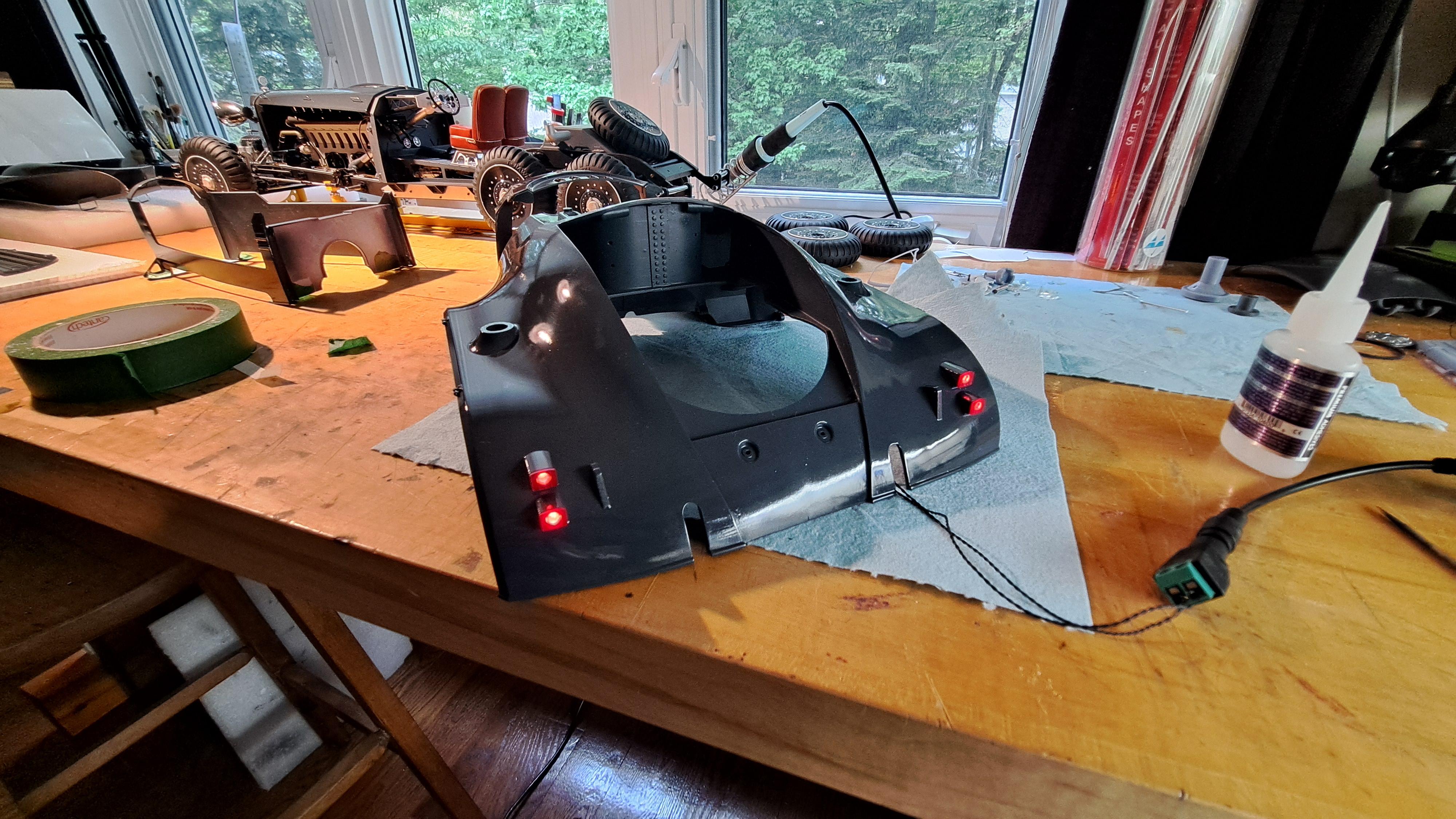
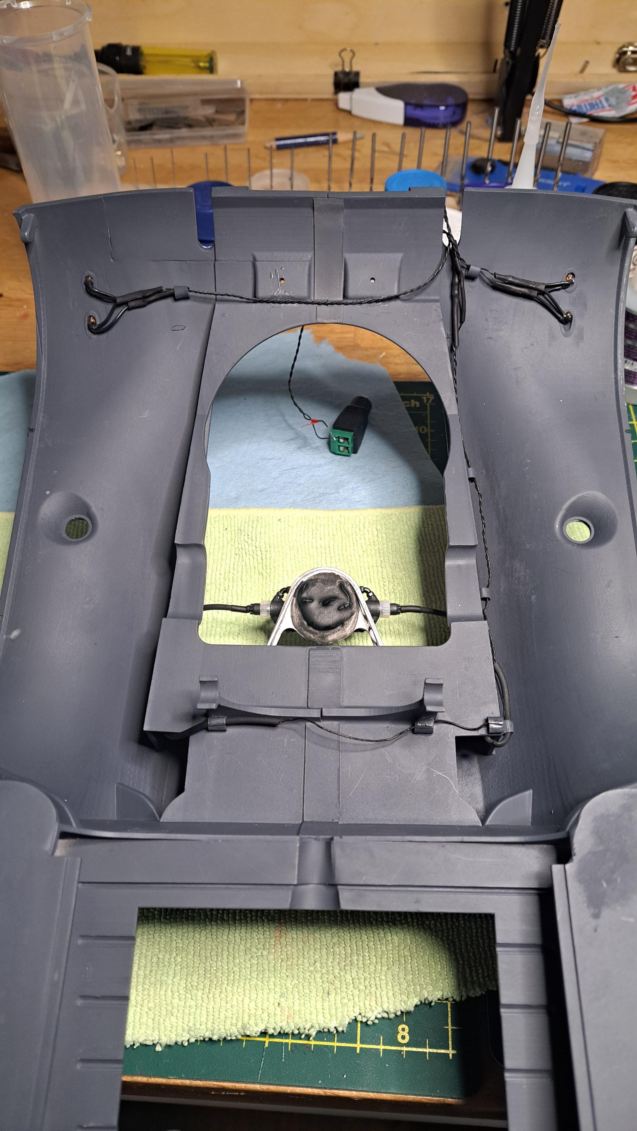
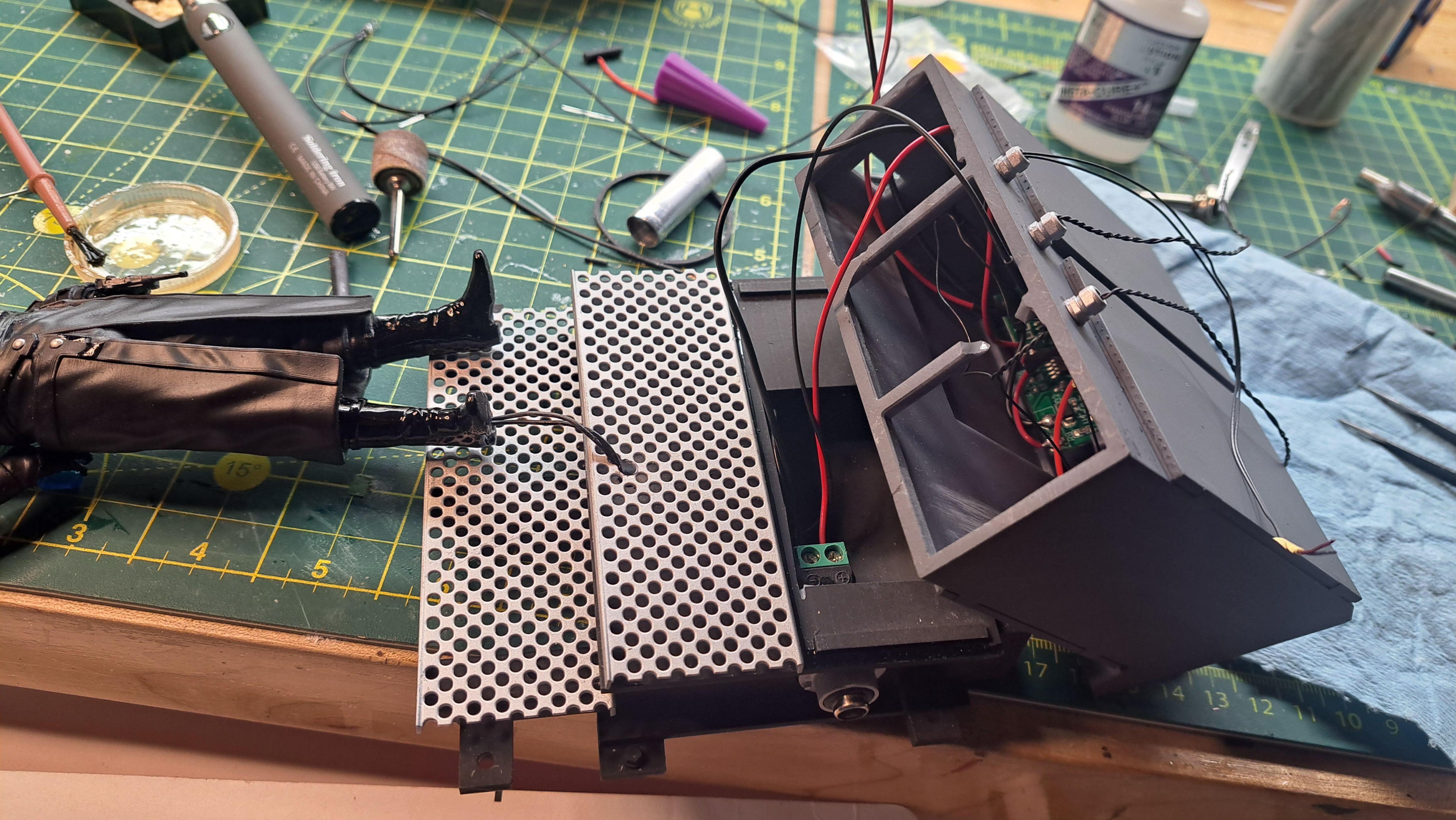
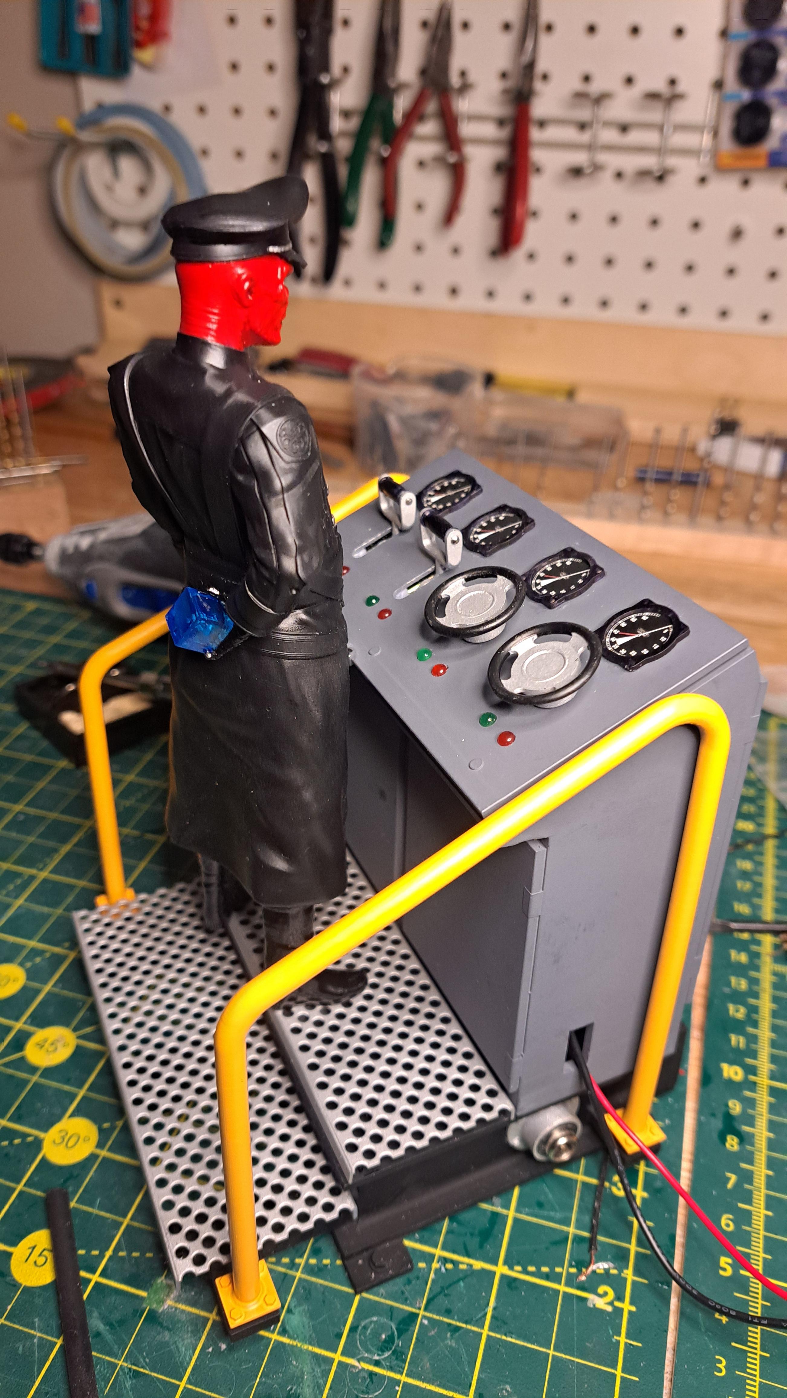
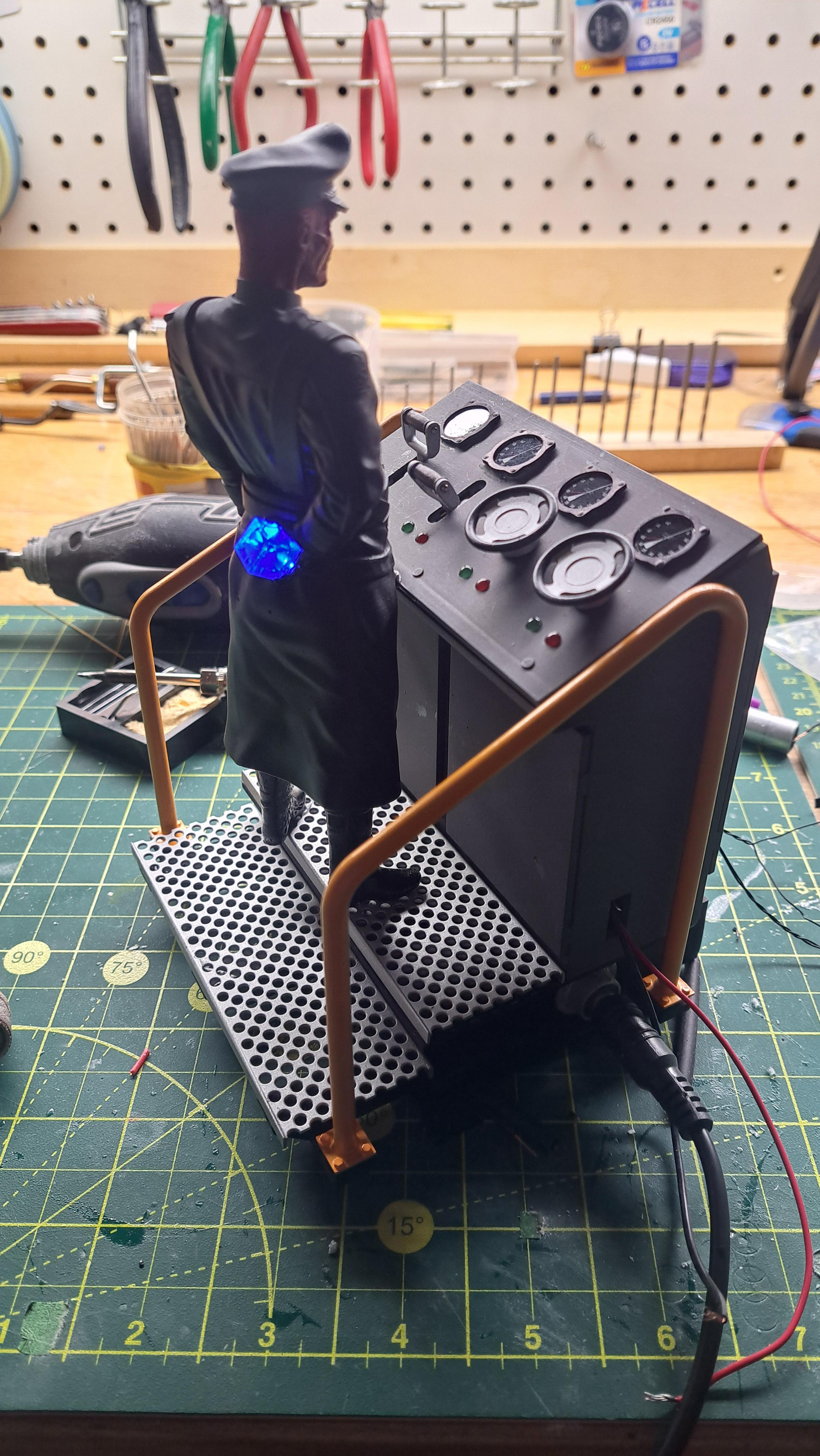
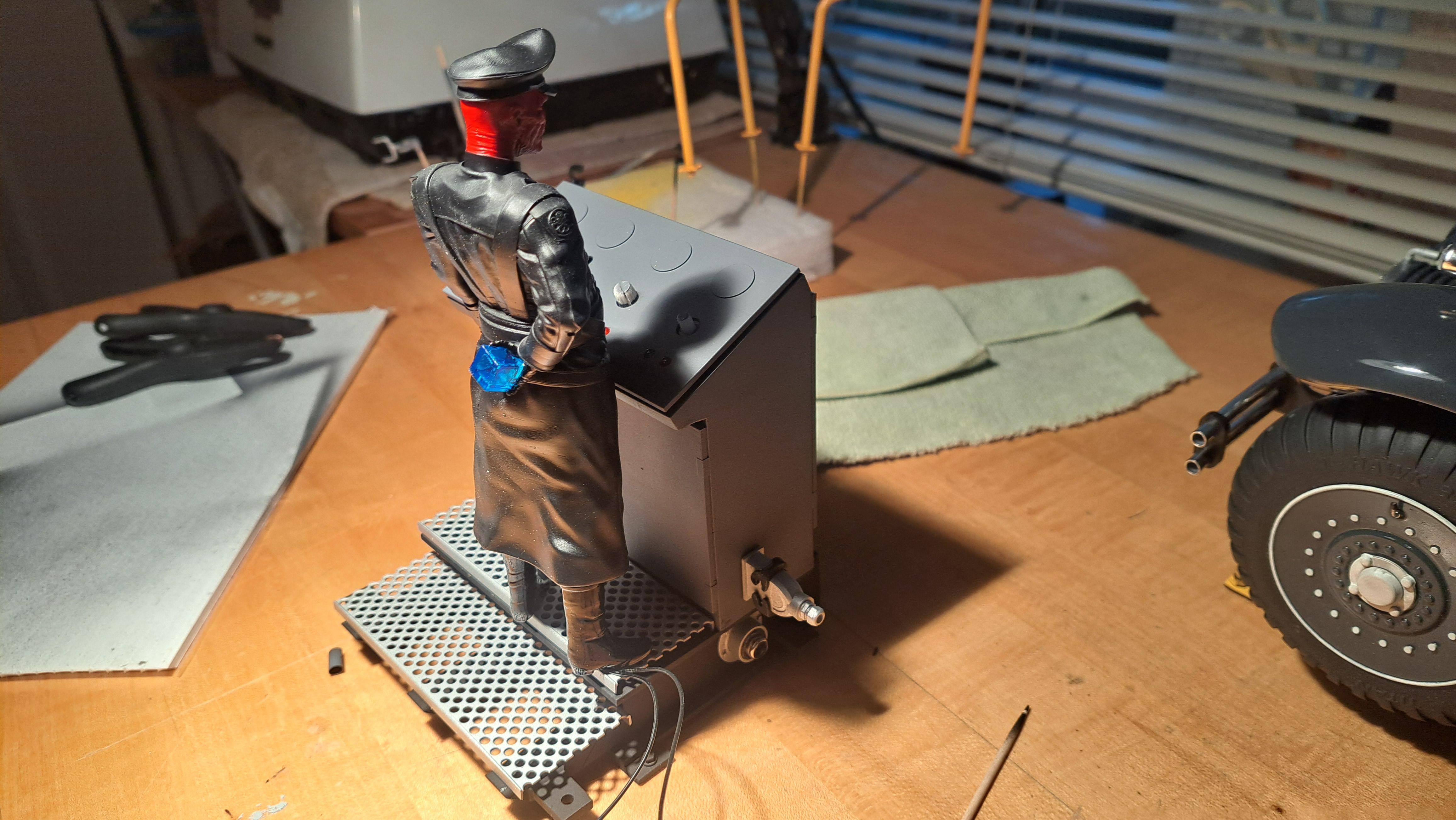
The control console is all done, and it was a pain to do. A lot of wiring and let's say wiring is not my specialty. Hopefully, everything will work as planned once hooked up to the car. I tested the circuits with a small light buld as I went along and for now, it all works. I might do a bit of weathering eventually. A lot of wires Red and his switchs Working bleu cube 20250616_205345.mp4 General location of console in relation to the model
-
Marvel's Hydra coupe 1/12 scale full scratch build
François replied to François's topic in WIP: Model Cars
Thank you Bugatti fan. Not sure what the next one will be yet, I might take a little break. But I still need to do the display case for this one first. The top cover for the control console is finished complete with 2 levers to control the car lights and cubes plus 2 handwheels for controlling the motor and display lighting. Speaking of the display lighting, I found 2 types old theater spot lights. Both could be free standing or mounted on the display structure. Maybe 1 spot per corner aimed at the model? TBD... console cover Old theater spot lights, l like both styles but I think the second one if more "Marvelish" in a doomsday/death ray kinda way. Any thoughts/comments welcomed
-
Marvel's Hydra coupe 1/12 scale full scratch build
François replied to François's topic in WIP: Model Cars
I printed all the parts for the control console set up, should turn out good. Test fit before paint Potentionmeters and switchs in place Test fit after paint
-
Marvel's Hydra coupe 1/12 scale full scratch build
François replied to François's topic in WIP: Model Cars
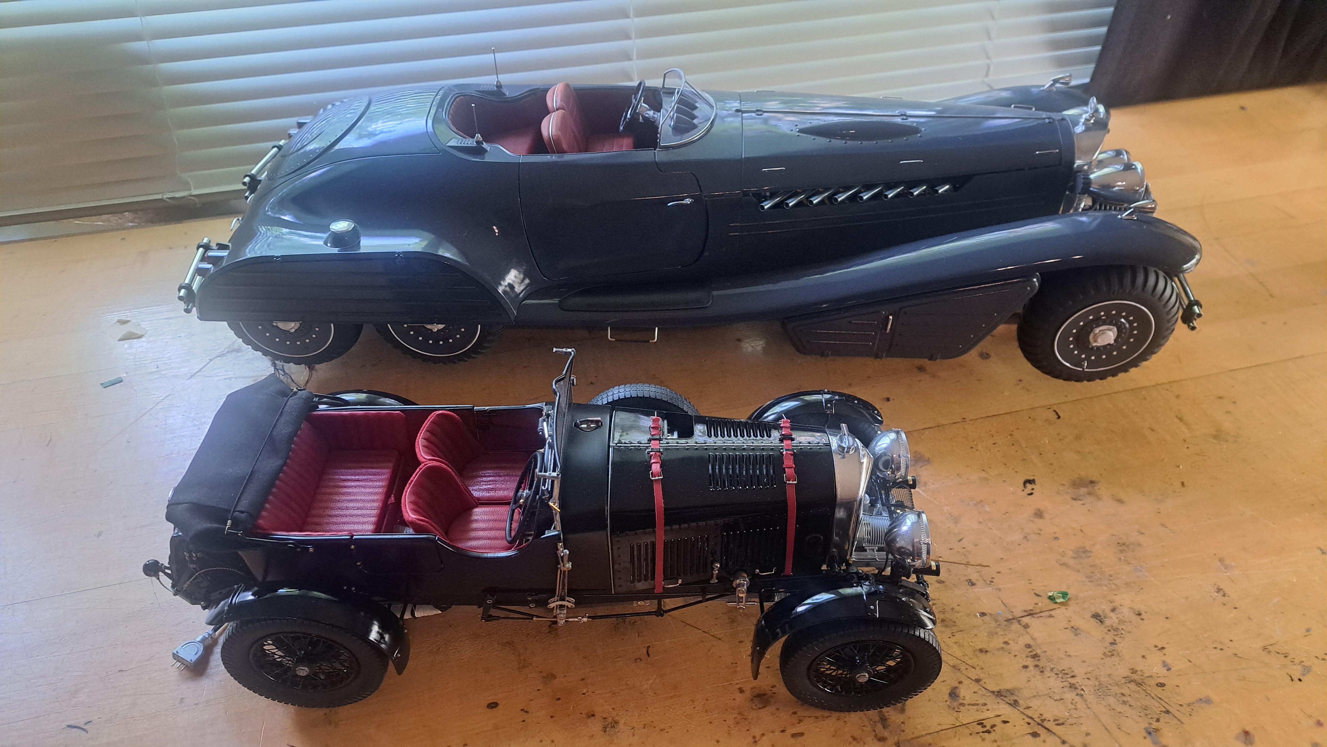
Thank you everyone, much appreciated. I was asked to take a few pictures of the Hydra next to my other models. They are all 1/12 scale! The hydra is a beast.
-
Marvel's Hydra coupe 1/12 scale full scratch build
François replied to François's topic in WIP: Model Cars
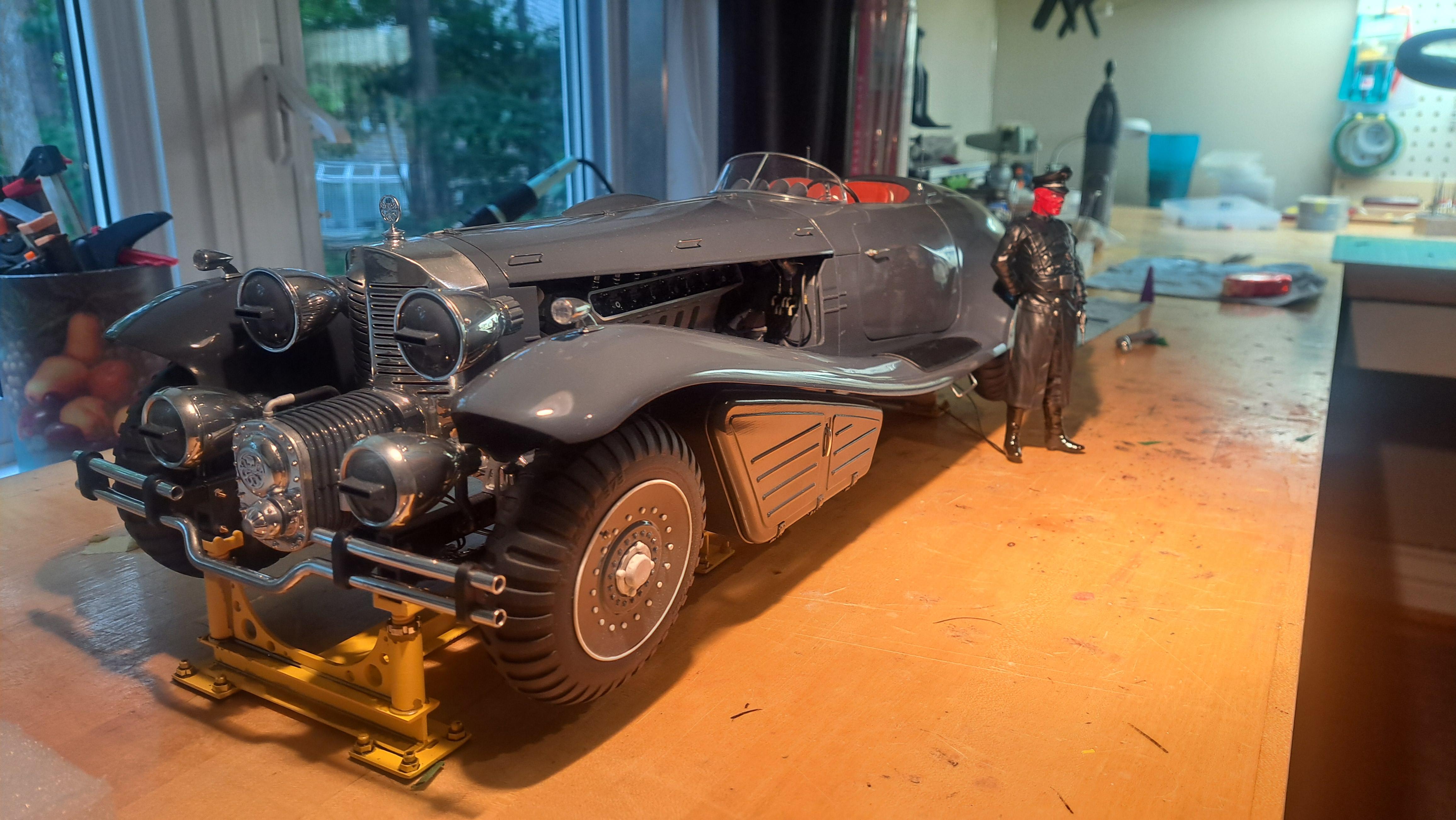
Well, it is done. Took me 11 months but it is done. And a reminder of the goal To view the finished album Hydra coupe final gallery
-
Marvel's Hydra coupe 1/12 scale full scratch build
François replied to François's topic in WIP: Model Cars
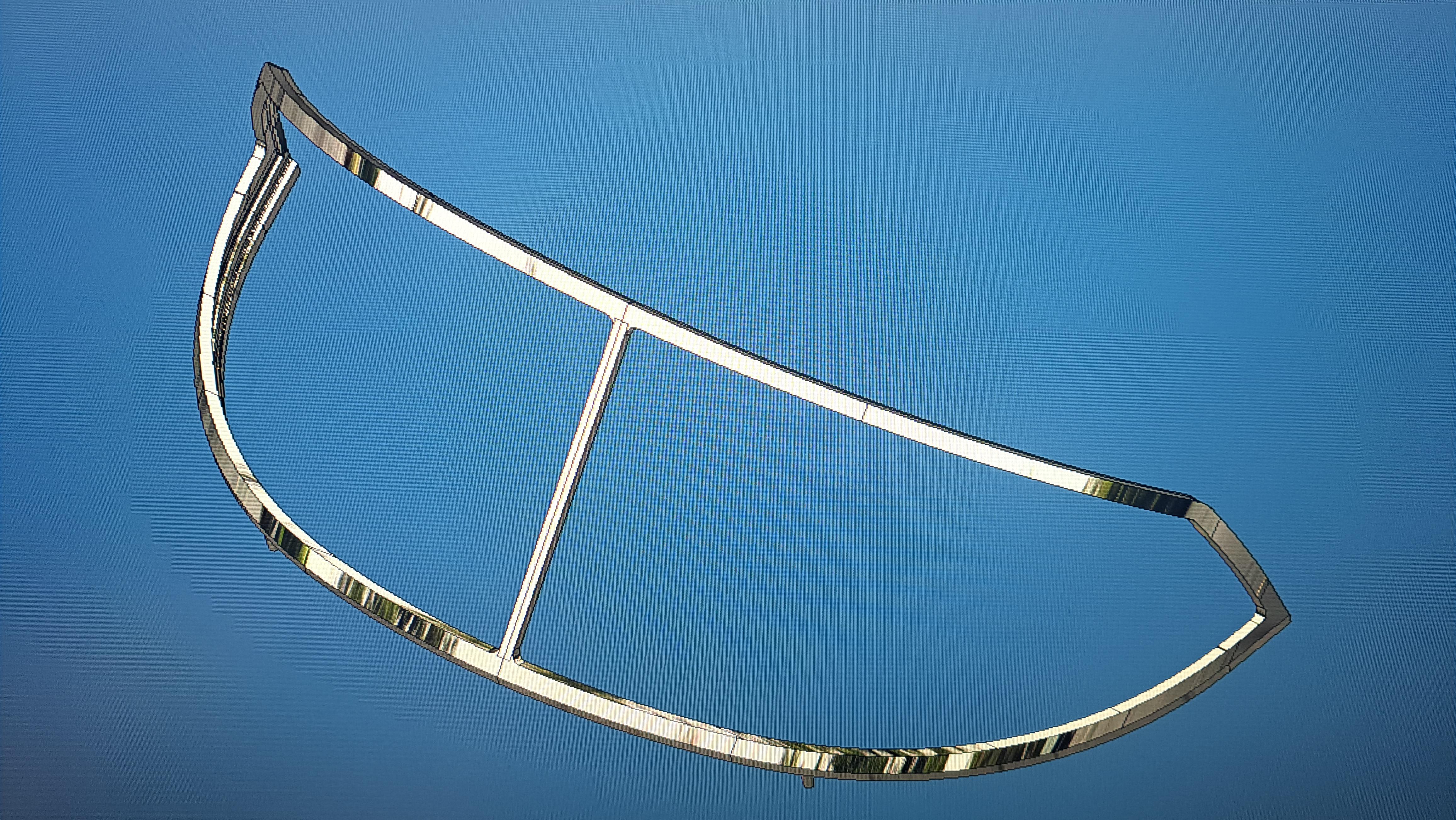
Thank you everyone. Mattilacken, inventor is effectively not very well suited for these kind of shapes. I've been using it for many many years to design machines, so manly squarish parts. The body on this project proved to be very challenging and quite frankly, I had my doughts at first. Here's s print screen wirh tge left side bar showing the steps I used to model the basic fender. Many more steps were needed to properly define the mating edge between the fender and body but it gives you and idea.
-
Marvel's Hydra coupe 1/12 scale full scratch build
François replied to François's topic in WIP: Model Cars
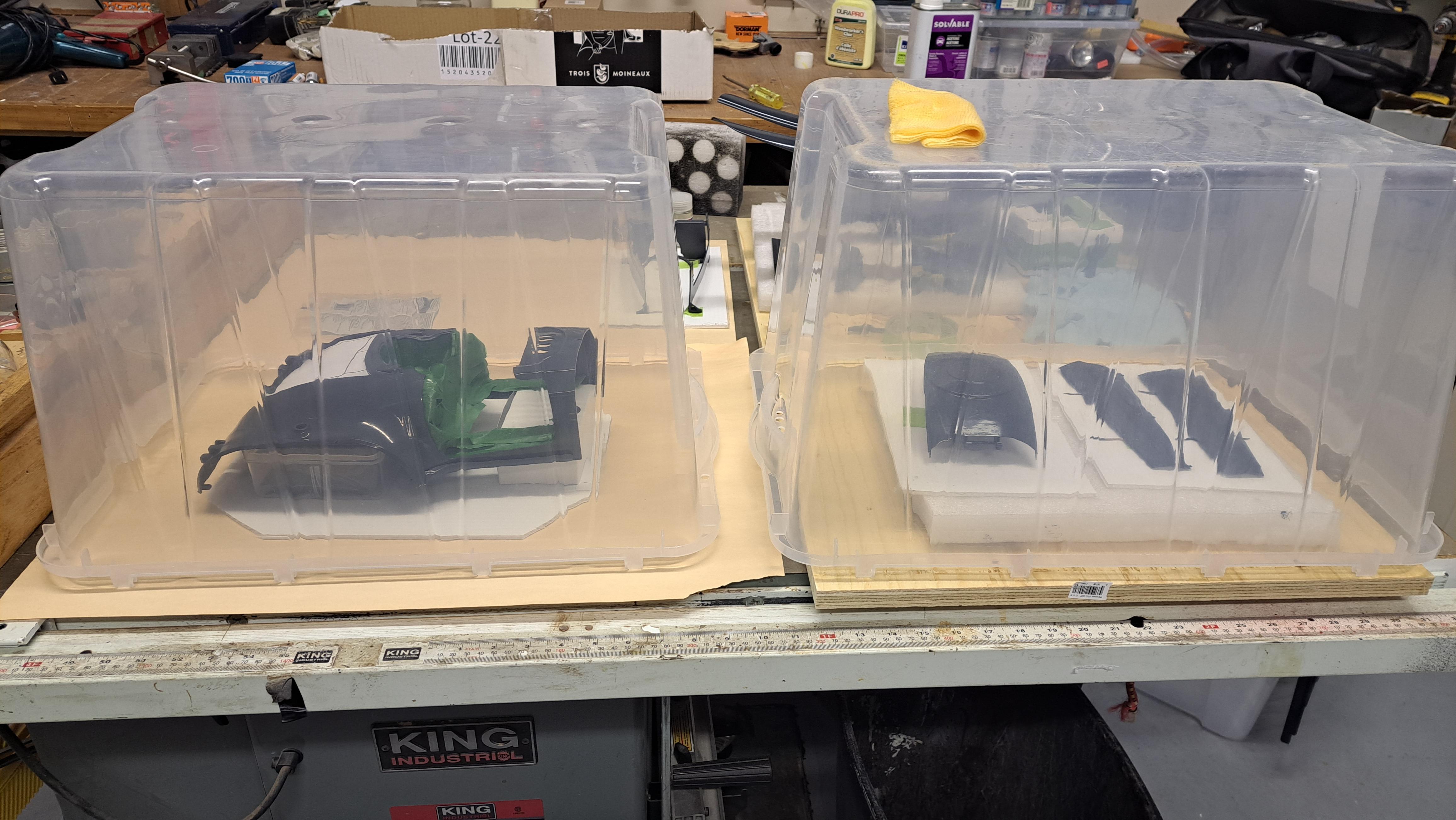
Yes, the idea I have is to sit the model on the yellow rack on a sheet of glass and to install a mirror at an angle under the glass. I think that the angled mirror will give a better view. I need to test this before because tge angle would be small. -
Marvel's Hydra coupe 1/12 scale full scratch build
François replied to François's topic in WIP: Model Cars
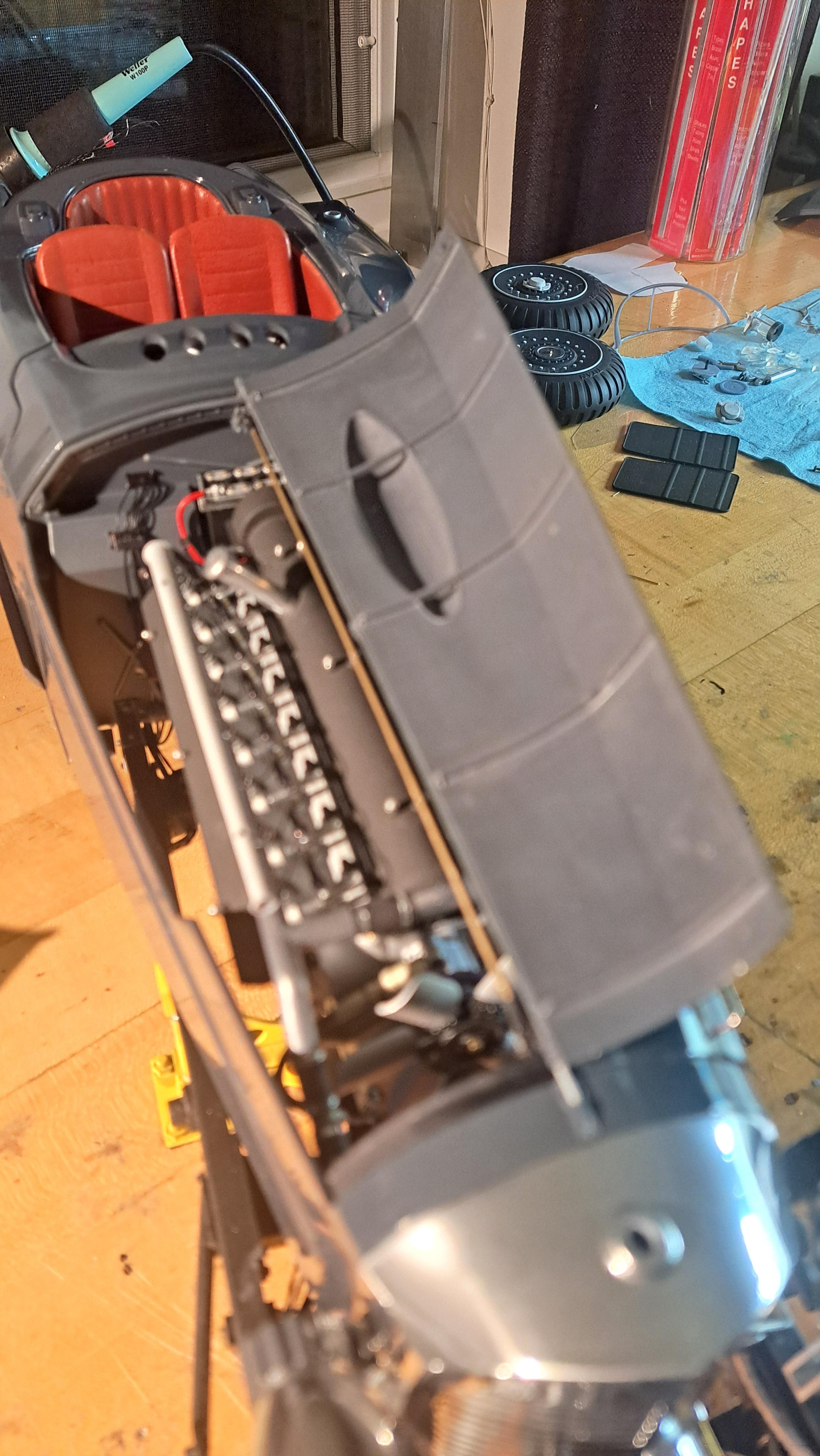
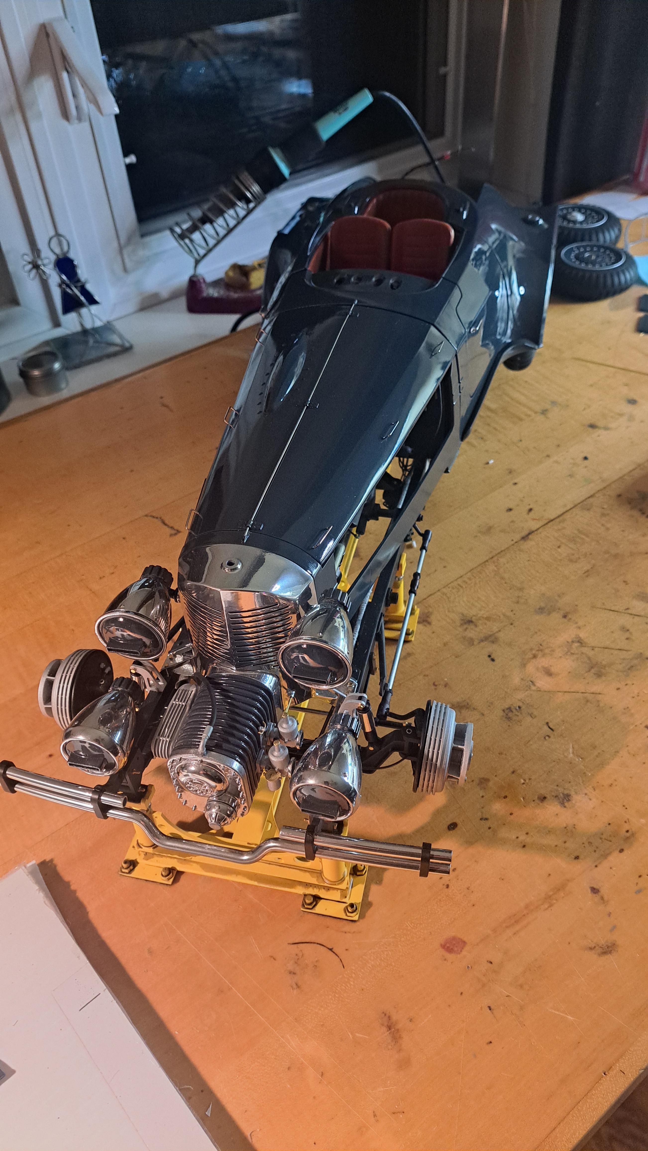
Well, the car itself is almost done. Just need to install the exhaust pipes to conclude this portion of this project. I've started the design of the control panel where the red skull figurine will be. I couldn't find a 3d modeled red skull that could be opened in Inventor (the model I used to print is a mesh model so to heavy and complicated to use) but I found another model that will do the job for now. And I'm slowly modeling the display case. Here are a few pictures of the almost completed car. I'll take proper pictures shortly. The control panel with the faux red skull And the display so far
-
Marvel's Hydra coupe 1/12 scale full scratch build
François replied to François's topic in WIP: Model Cars
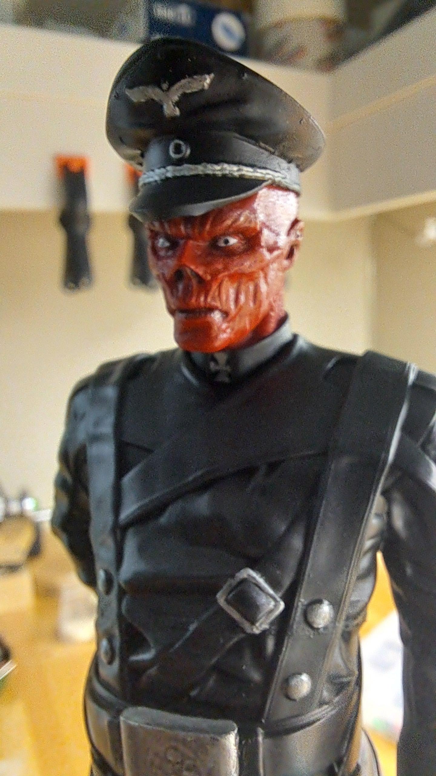
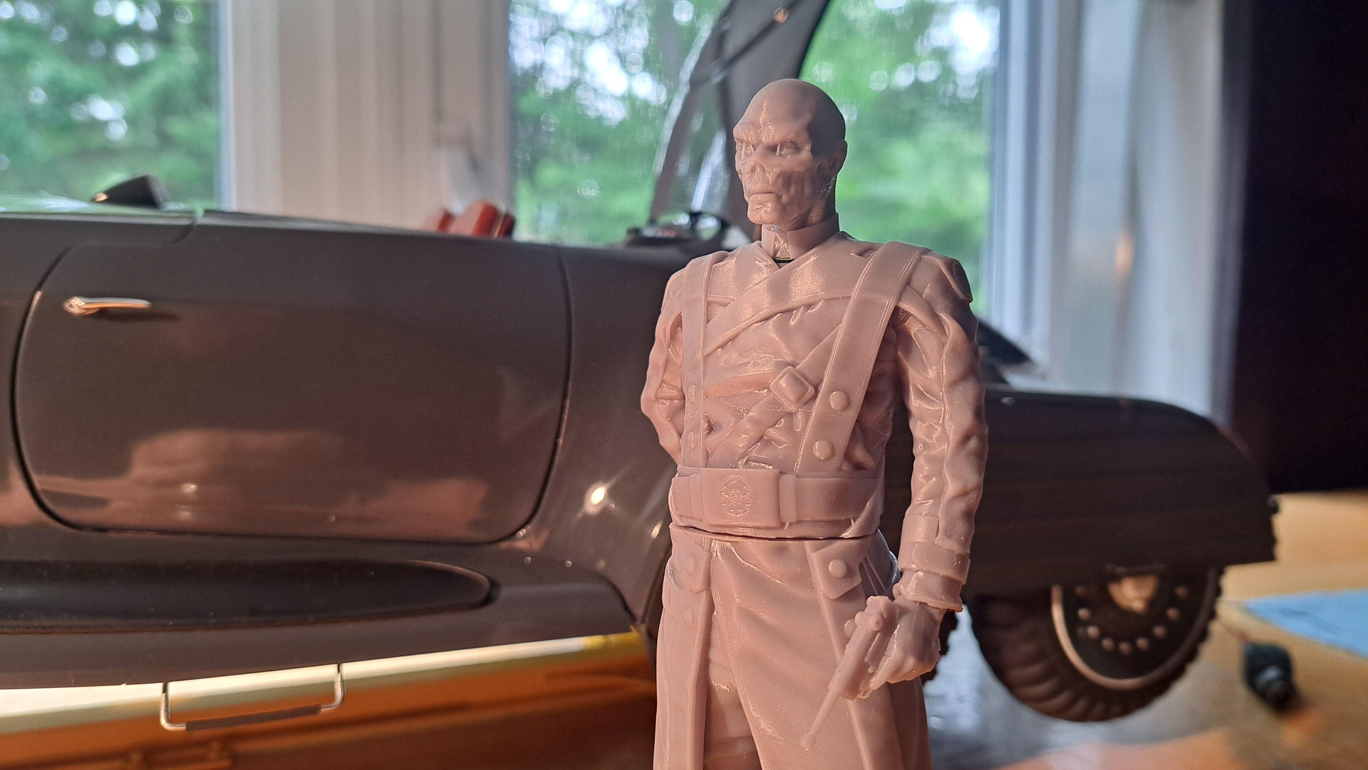
I'm done with the figurine. It's my first try at something like this but I think it came out good.
-
Marvel's Hydra coupe 1/12 scale full scratch build
François replied to François's topic in WIP: Model Cars
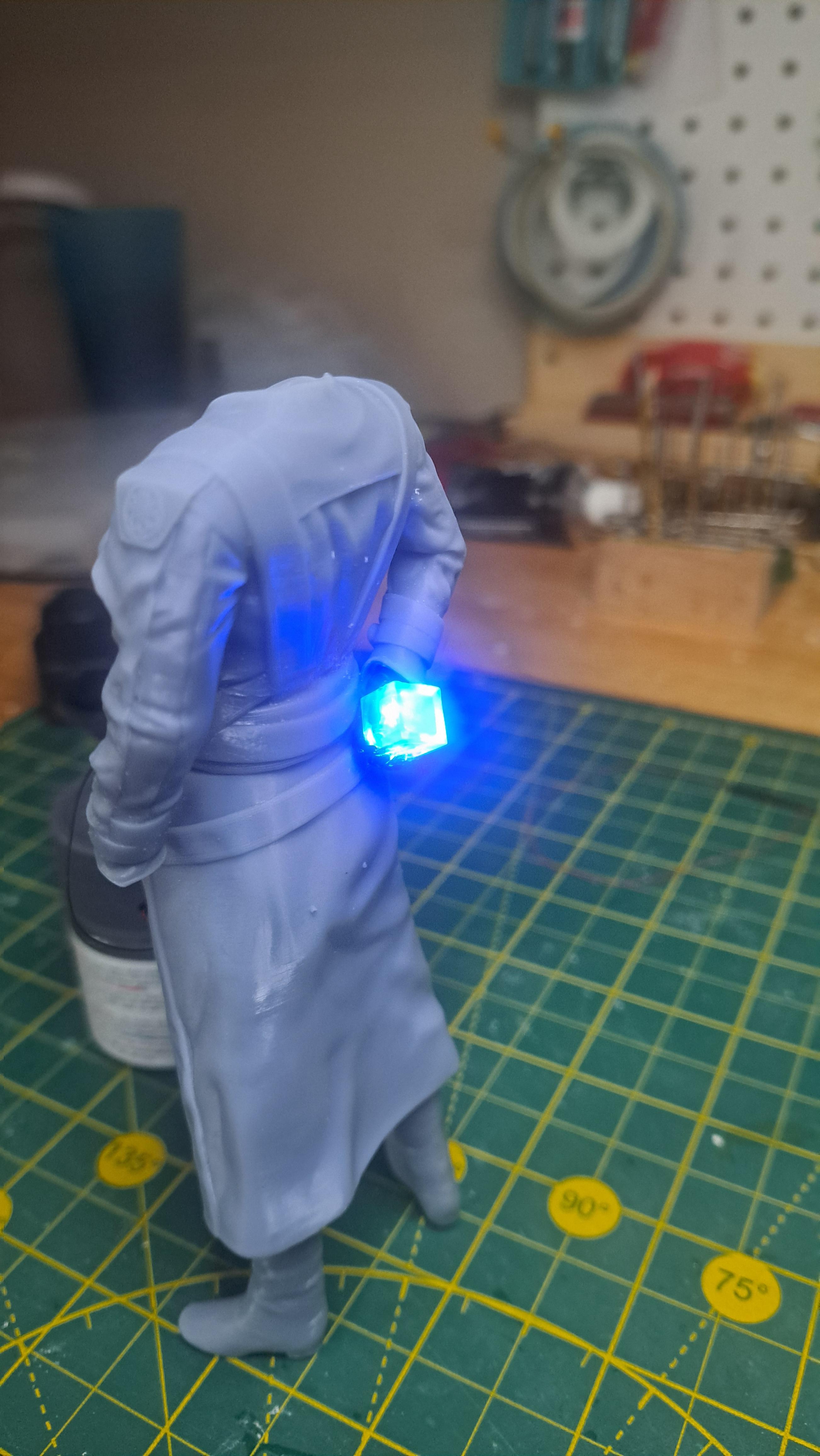
The red skull figurine holds a cube in is right hand behind is back. It's the same cube that I but in the thingy in the trunk. I thought it would be fun to have it glow by Inserting a pico led in it. So I printed the hand in clear resin, made an access hole from the wrist to the cube and inserted the led inside. I painted the glove black and the cube a translucide bleu. The wires go up the arm, into the torso, down the right leg and out under the right foot. Looks kinda neat. Here's a picture of what I think is CG image of the back side of the figurine with the glowing cube. Here's mine
-
Marvel's Hydra coupe 1/12 scale full scratch build
François replied to François's topic in WIP: Model Cars
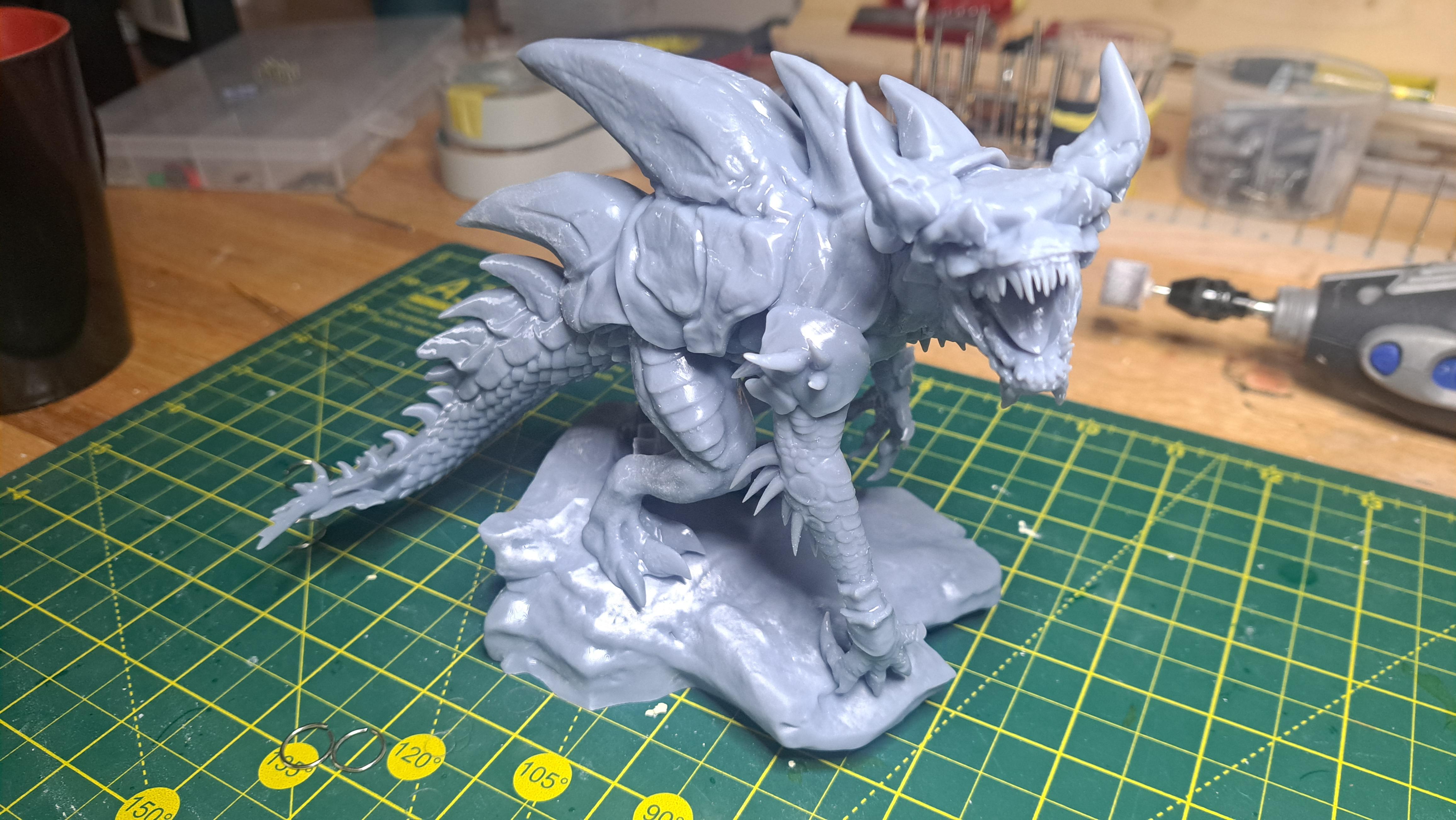
Yesterday, my son asked me if I could print a large dragon for him and his budys for their dungeon and dragon game. He gave me the file and after about 7hrs of printing time, I had a complete and highly detailed dragon. This gave me the idea that I could maybe find a printable file of the red skull caracter that could be set in the display case. After about 5 minutes of search, I found a file for 5$. I had to scale it down a bit, the actor is 6ft 2in so I scaled it down by 33%. It came out great ! Just need to paint it. Here's the dragon And here's red skull
-
Marvel's Hydra coupe 1/12 scale full scratch build
François replied to François's topic in WIP: Model Cars
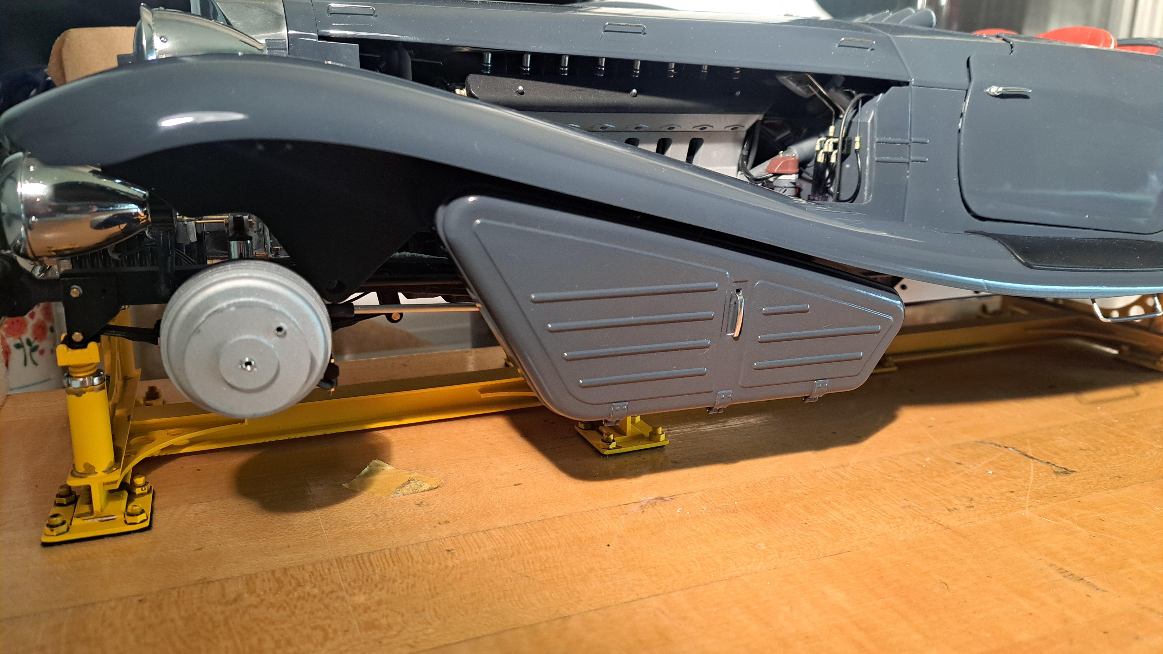
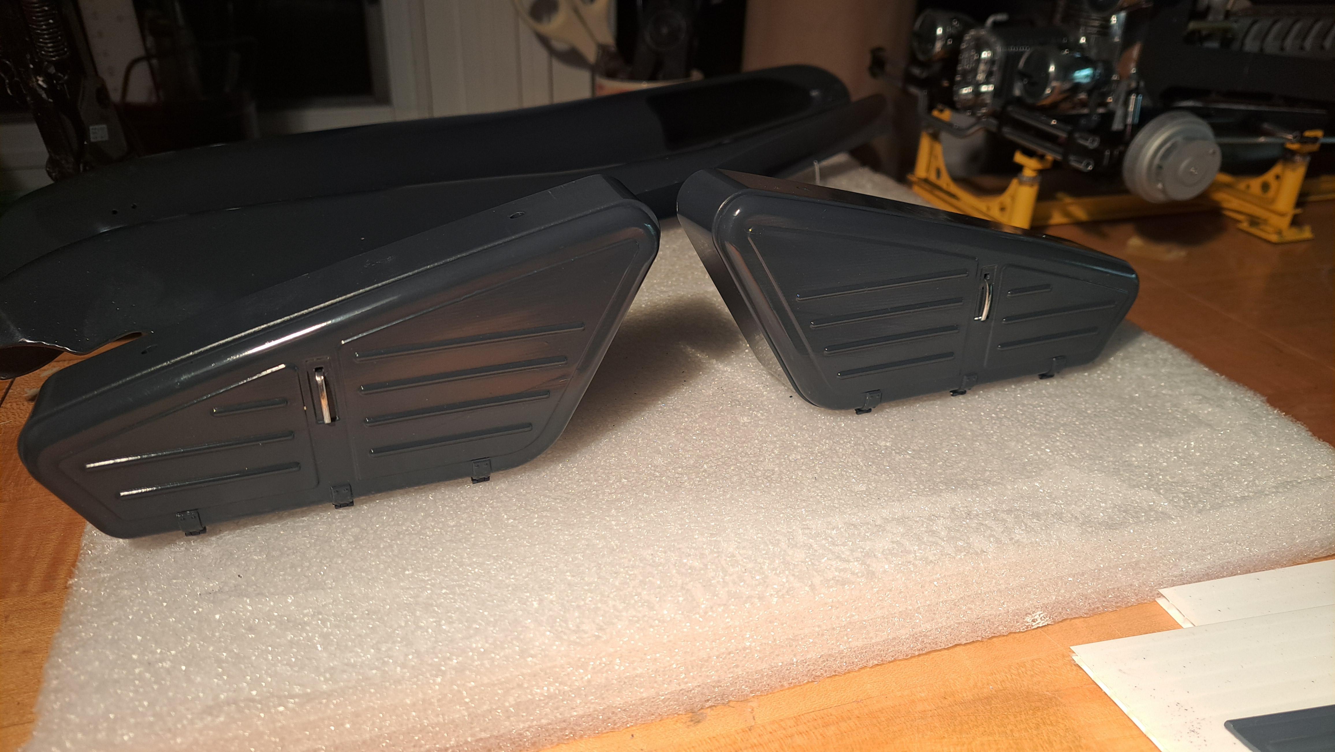
Thank you everyone ! Both side tool boxes are complete and ready to be installed. I redid the clear on the trunk lid, there was a spot where I sanded thru the clear and the paint, all the way to the darker primer. Now it ok. I just need to fabricate both lock handles and the lid will be ready for installation. and the trunk lid
-
Marvel's Hydra coupe 1/12 scale full scratch build
François replied to François's topic in WIP: Model Cars
Thanks Bk9300, my confidence in what I'm able to do is effectively pretty high. I just repaired my printer and am testing it. Let's just say that my confidence in the printer is not as high. -
Marvel's Hydra coupe 1/12 scale full scratch build
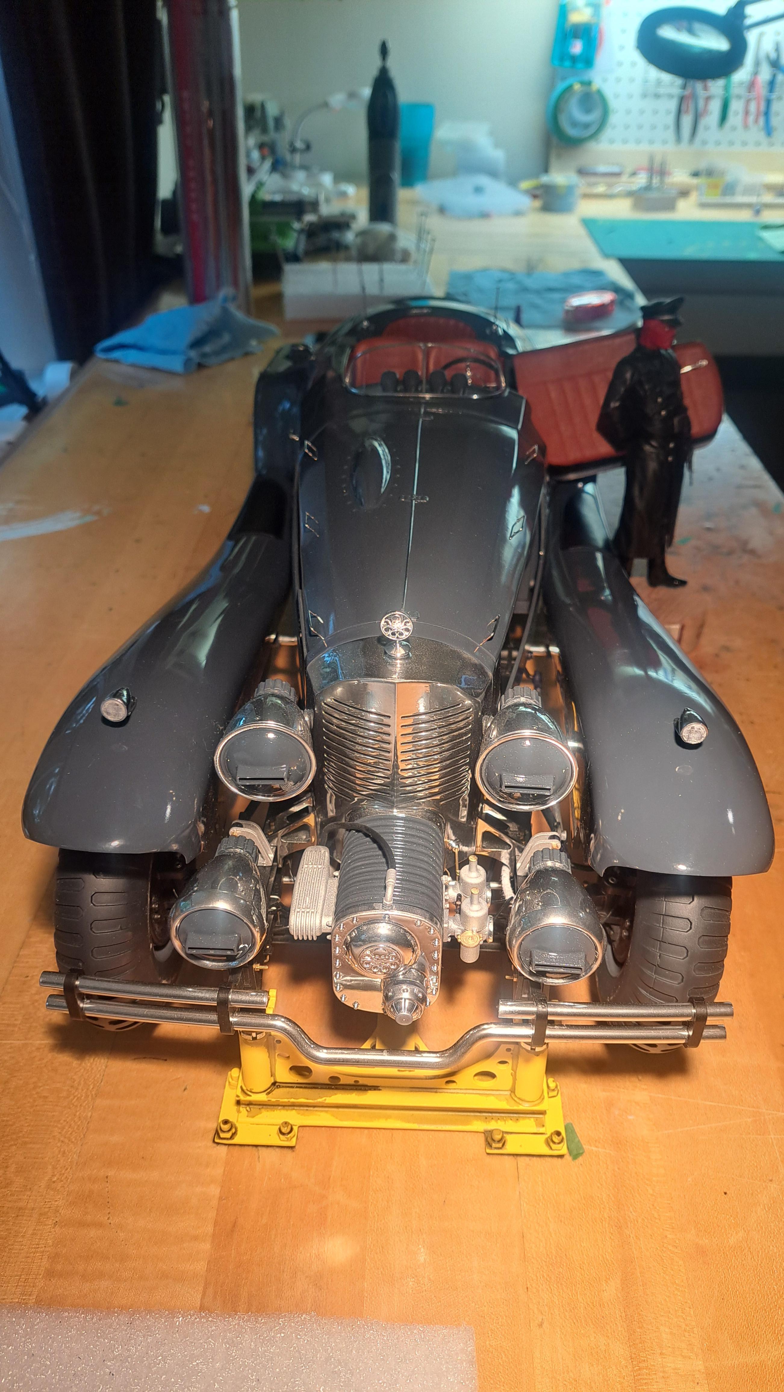
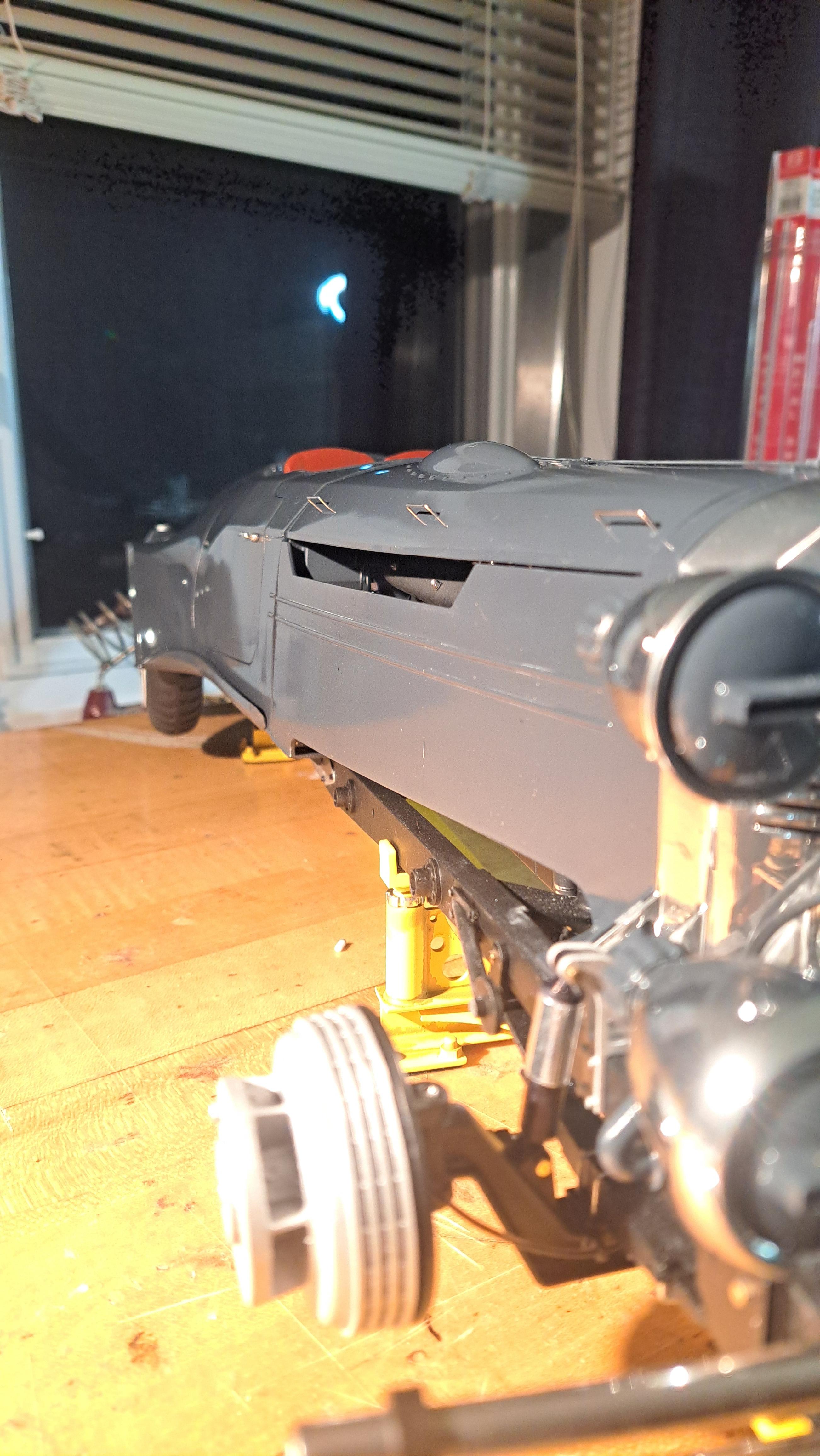
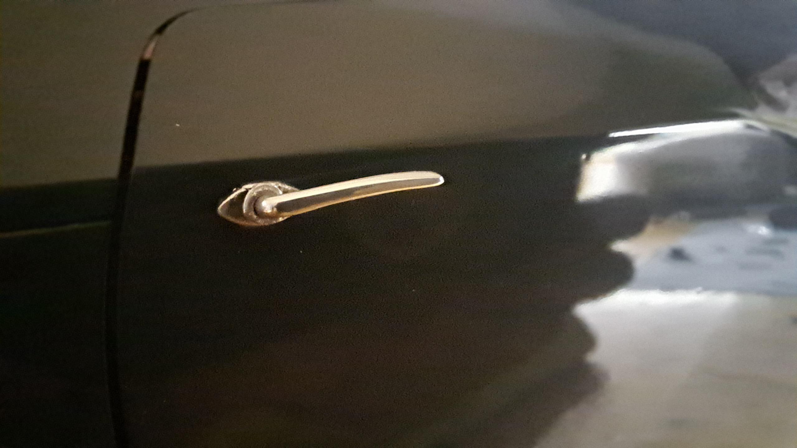
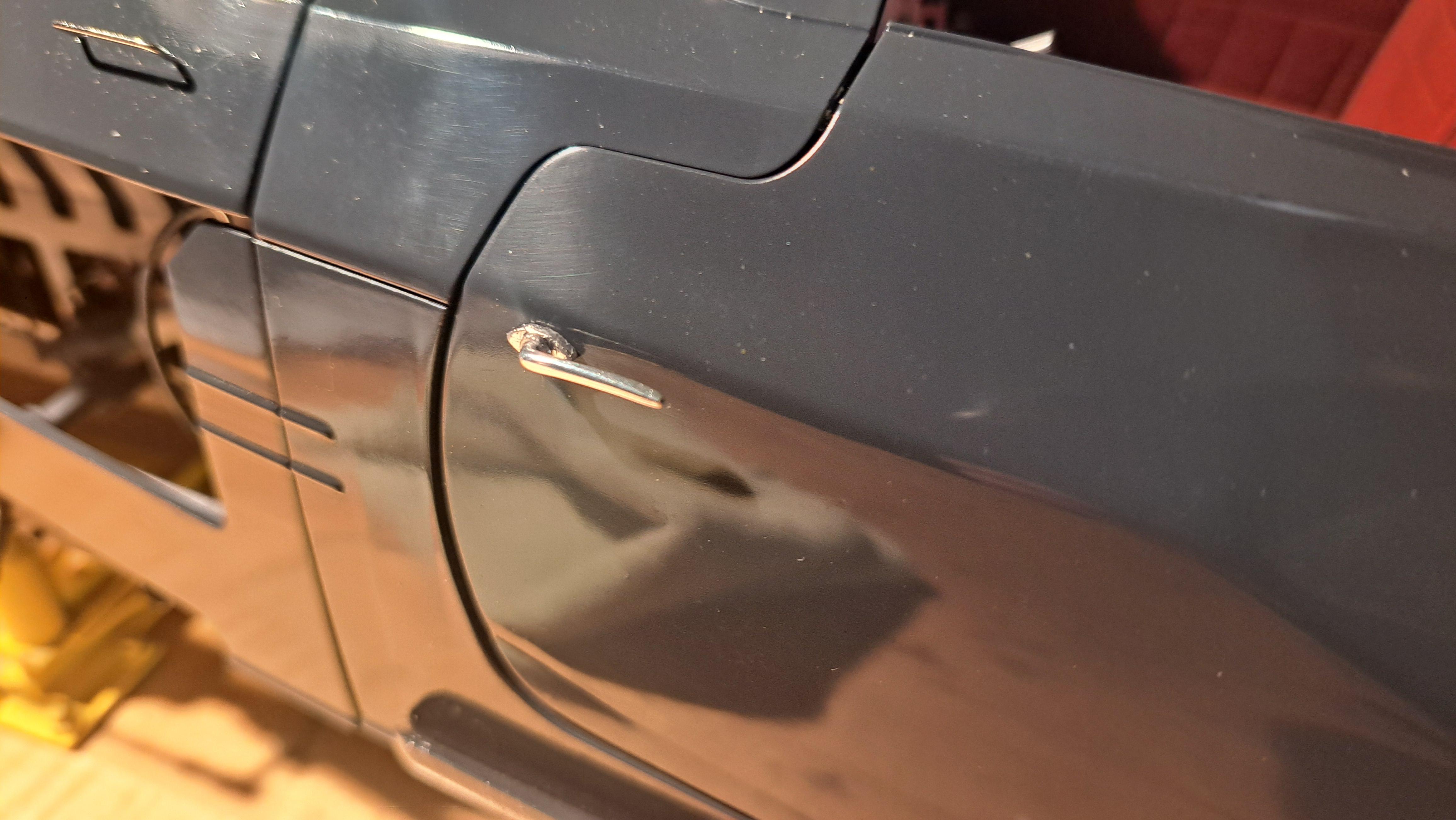
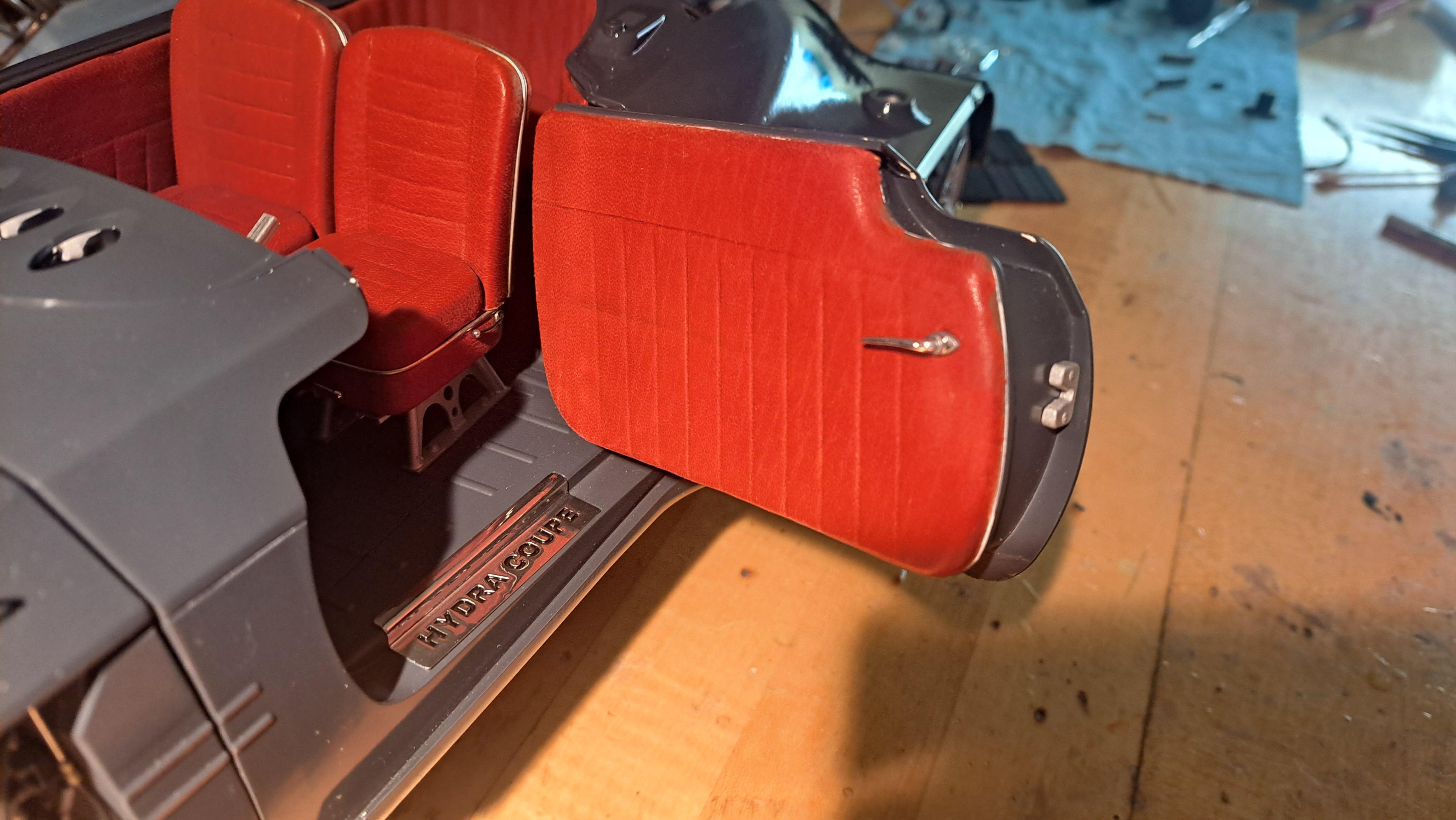
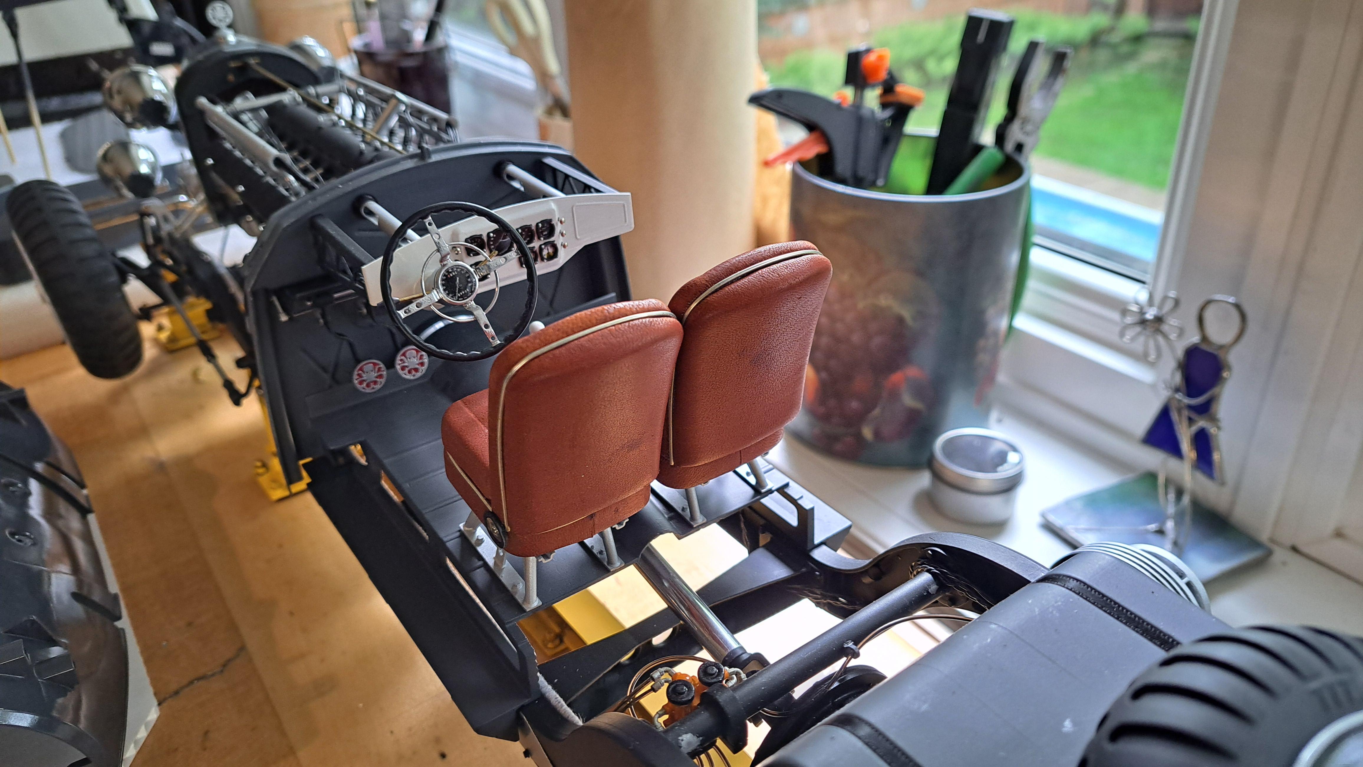
François replied to François's topic in WIP: Model Cars
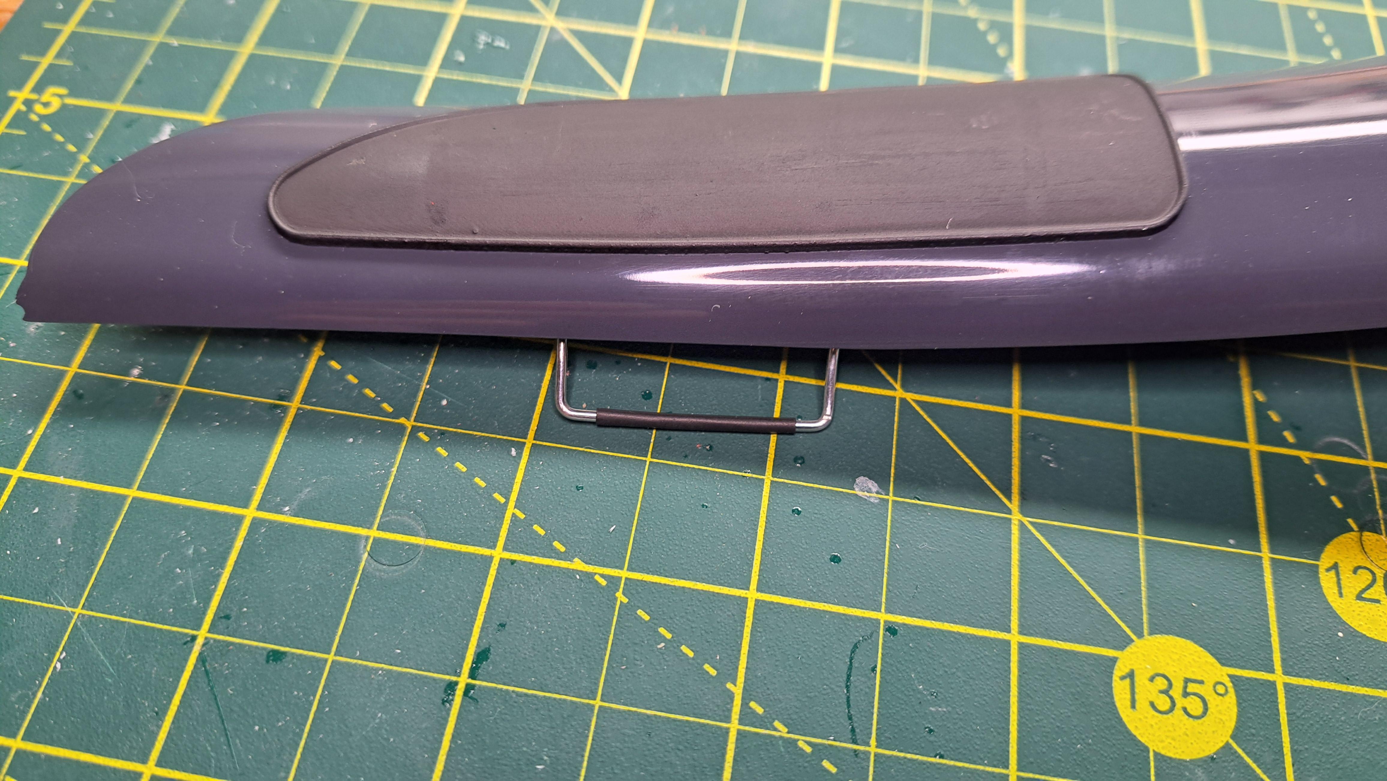
I am now at the last stage of this build (the car portion), so pretty much everything I do is final. Here's what's been done today. Installation of front body and hood, making sure fits are nice and hoods open and close freely. Installation of door sills Installation of door handles. Quick note about the handles. I 3d printed 6 handles, 2 per door and 2 for the trunk lid. They looked very nice but the chrome dulled right away during Installation. So I ended up make new once out of an aluminium rod. Once filed, curved and polished, they look better then the printed ones. Dulled printed handle Aluminium handle Inside handle and door catch Installed the doors on the body Installed the 4 gages above the dashboard And took a few general pictures cause it looks so nice!! I also took proper pictures of the car without body parts on it. Here's a link to the album. Hydra coupe final gallery
-
Marvel's Hydra coupe 1/12 scale full scratch build
François replied to François's topic in WIP: Model Cars
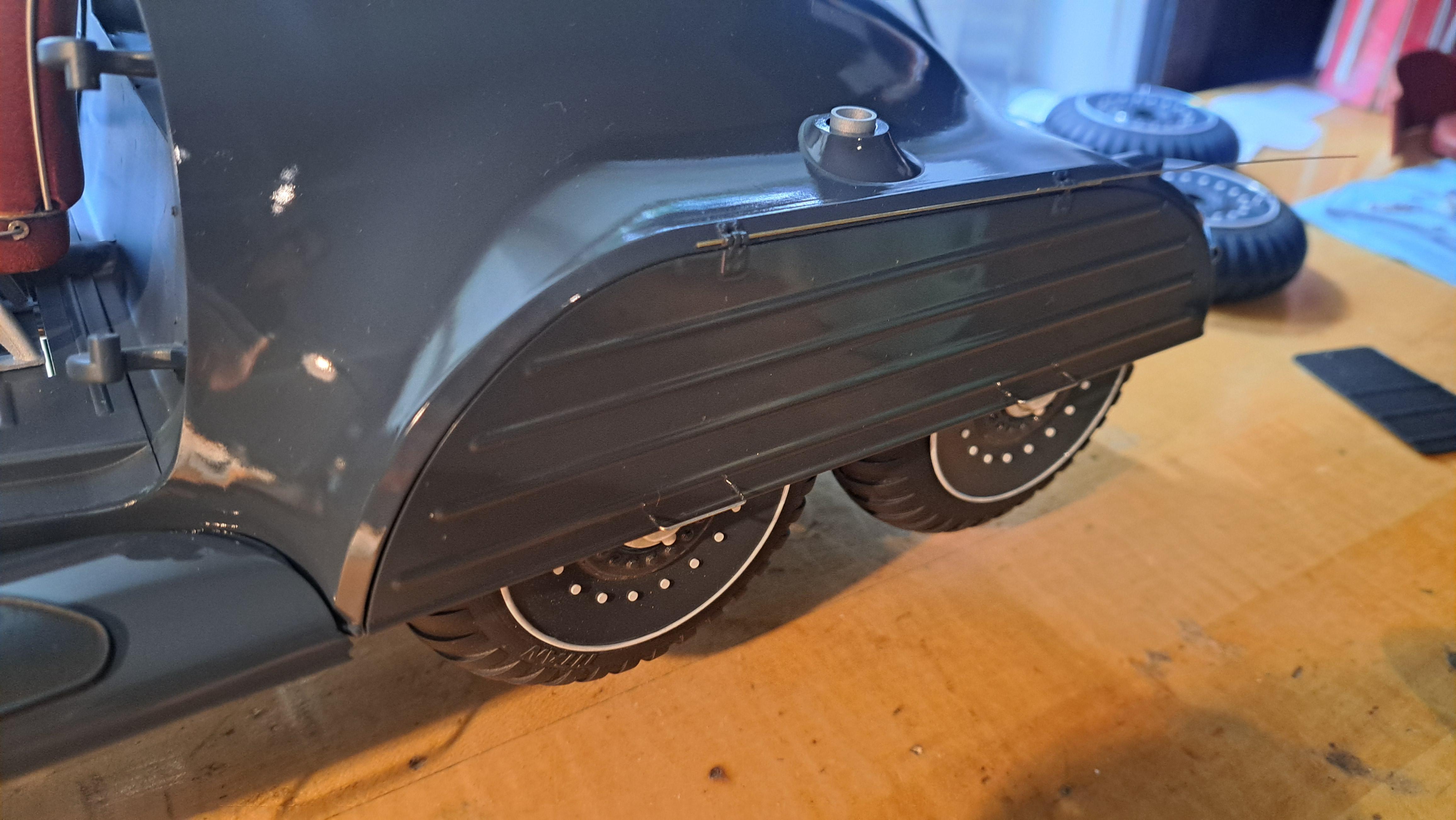
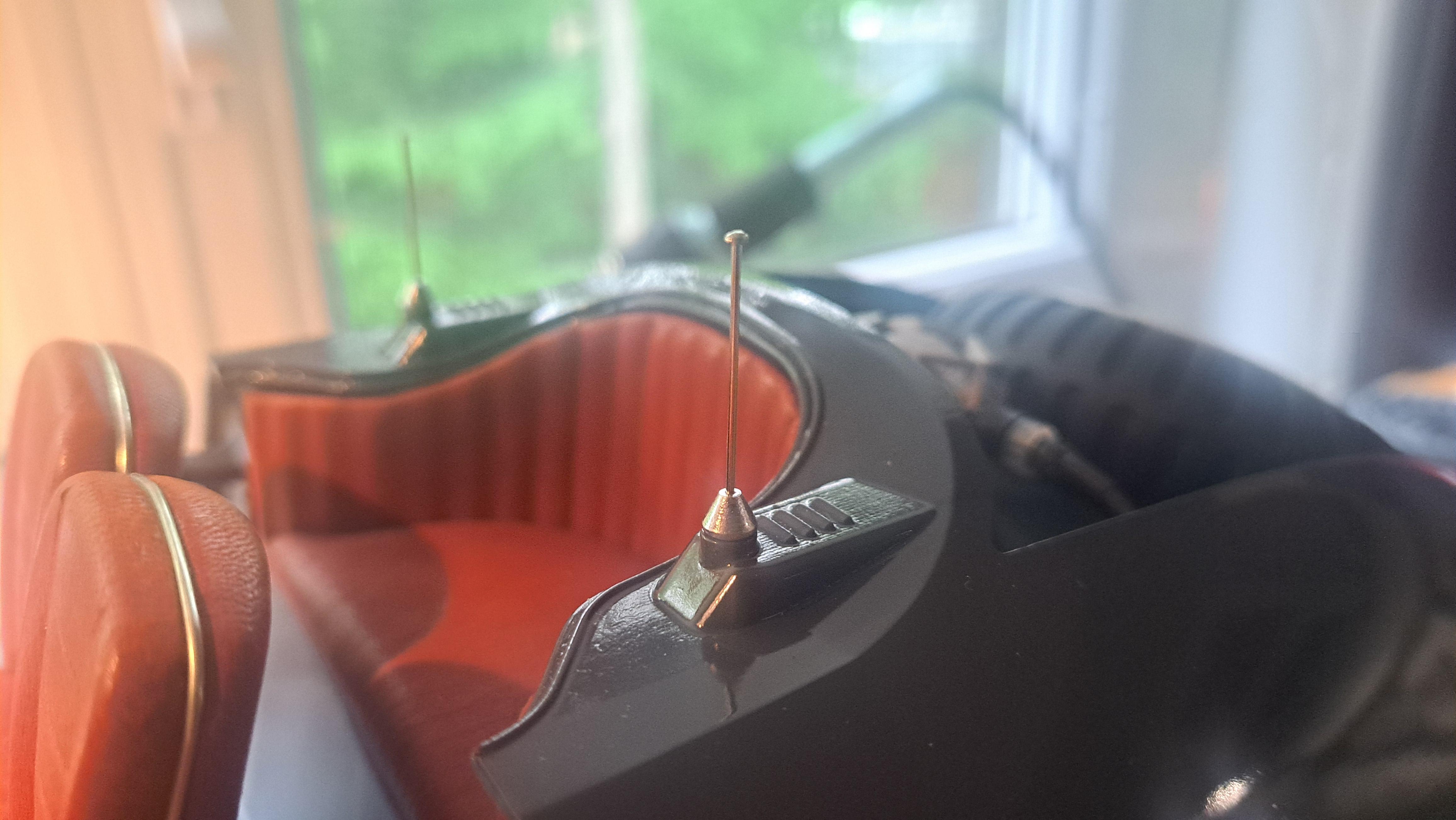
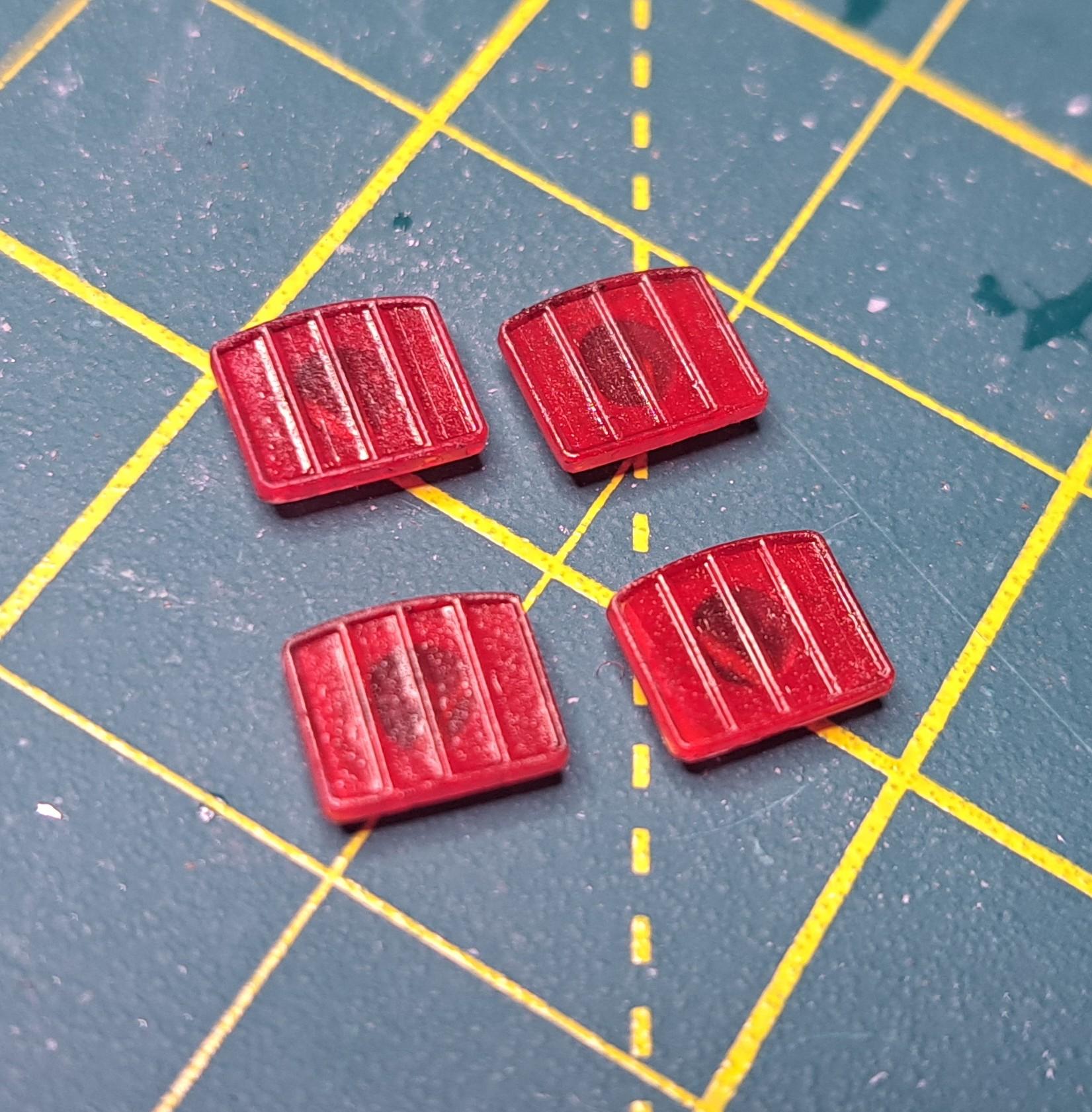
I started to dress up the body. There are many parts to attach, the rear light lenses, the wiring, the blue cube thingy, the rear seat, doors and door handles, trunk lid with handles, and list goes on. Here's what been done so far. Rear light lenses Real light wiring Bleu cube thingy Rear seat Test fit of antenna I also black out the door skills lettering and installed the handles on the rear wheels covers Hood handles
-
Marvel's Hydra coupe 1/12 scale full scratch build
François replied to François's topic in WIP: Model Cars
I'm slowly buffing every body pieces, it kinda nerve racking. One slip and I could ruin the part. So far, I've done both hood panels, both rear wheel covers and one fender. No slip up so far. I also installed the foot ladder and rubber mat on the one fender. And prepared the 4 rear light lenses.
-
Marvel's Hydra coupe 1/12 scale full scratch build
François replied to François's topic in WIP: Model Cars
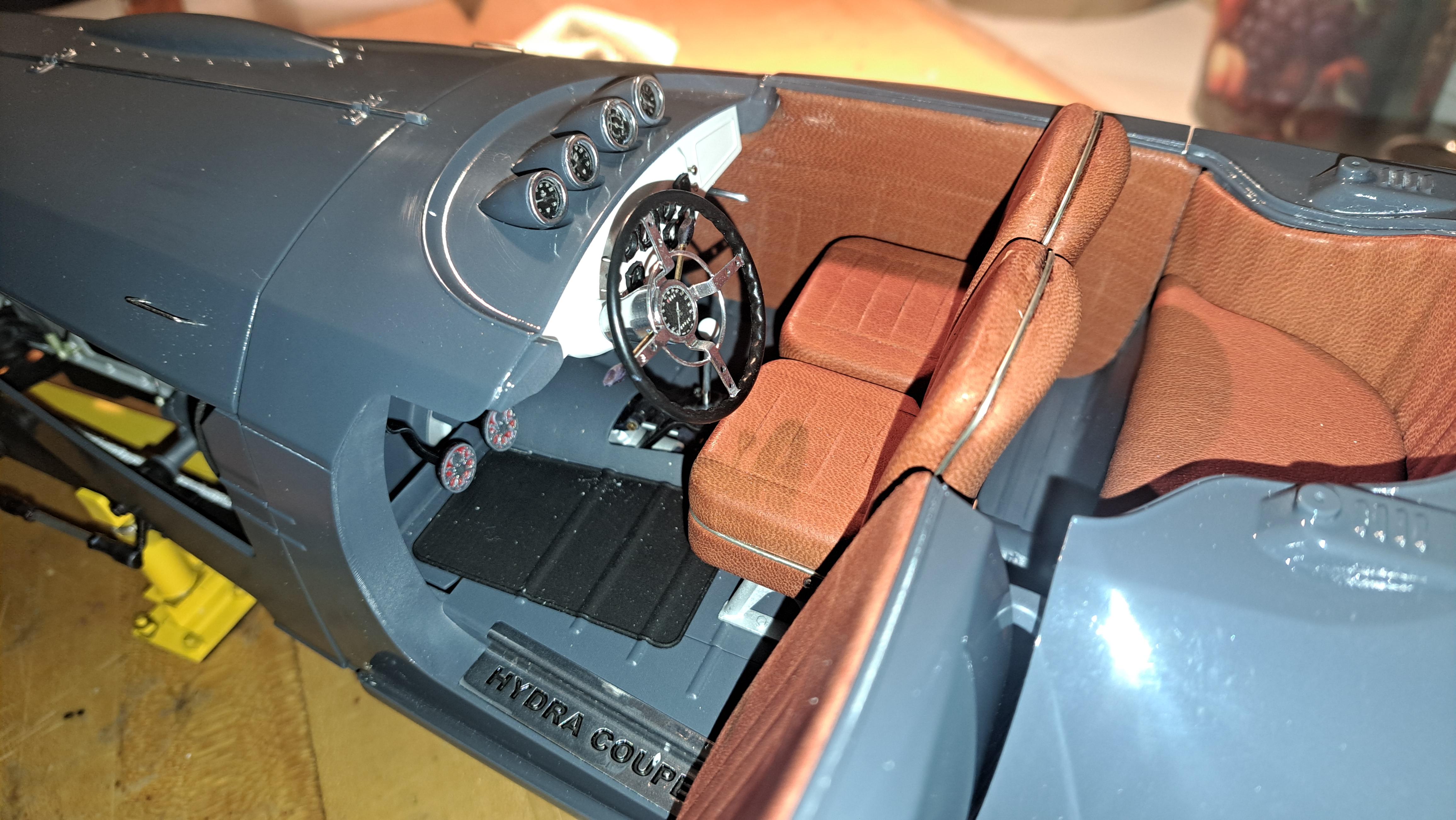
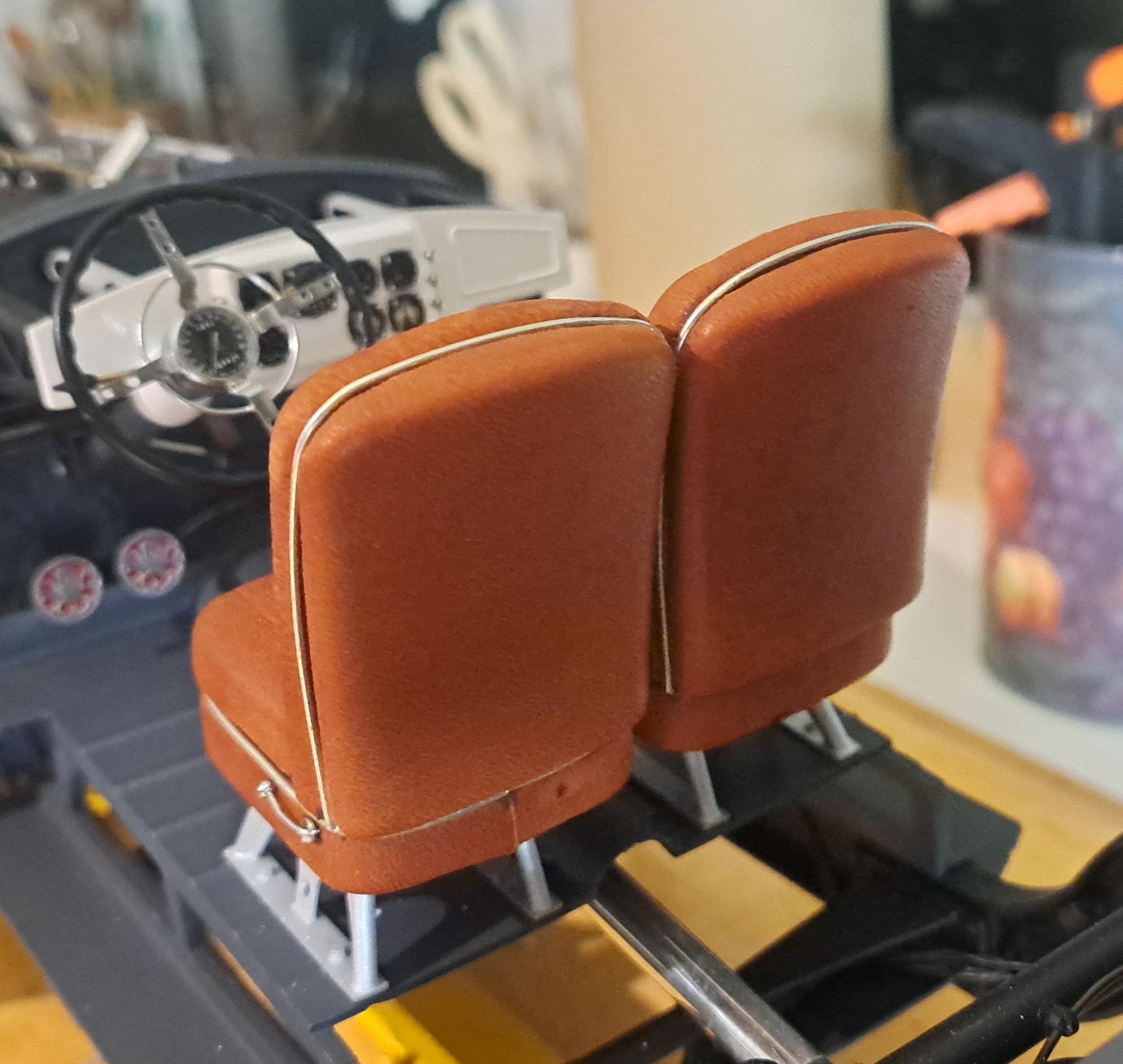
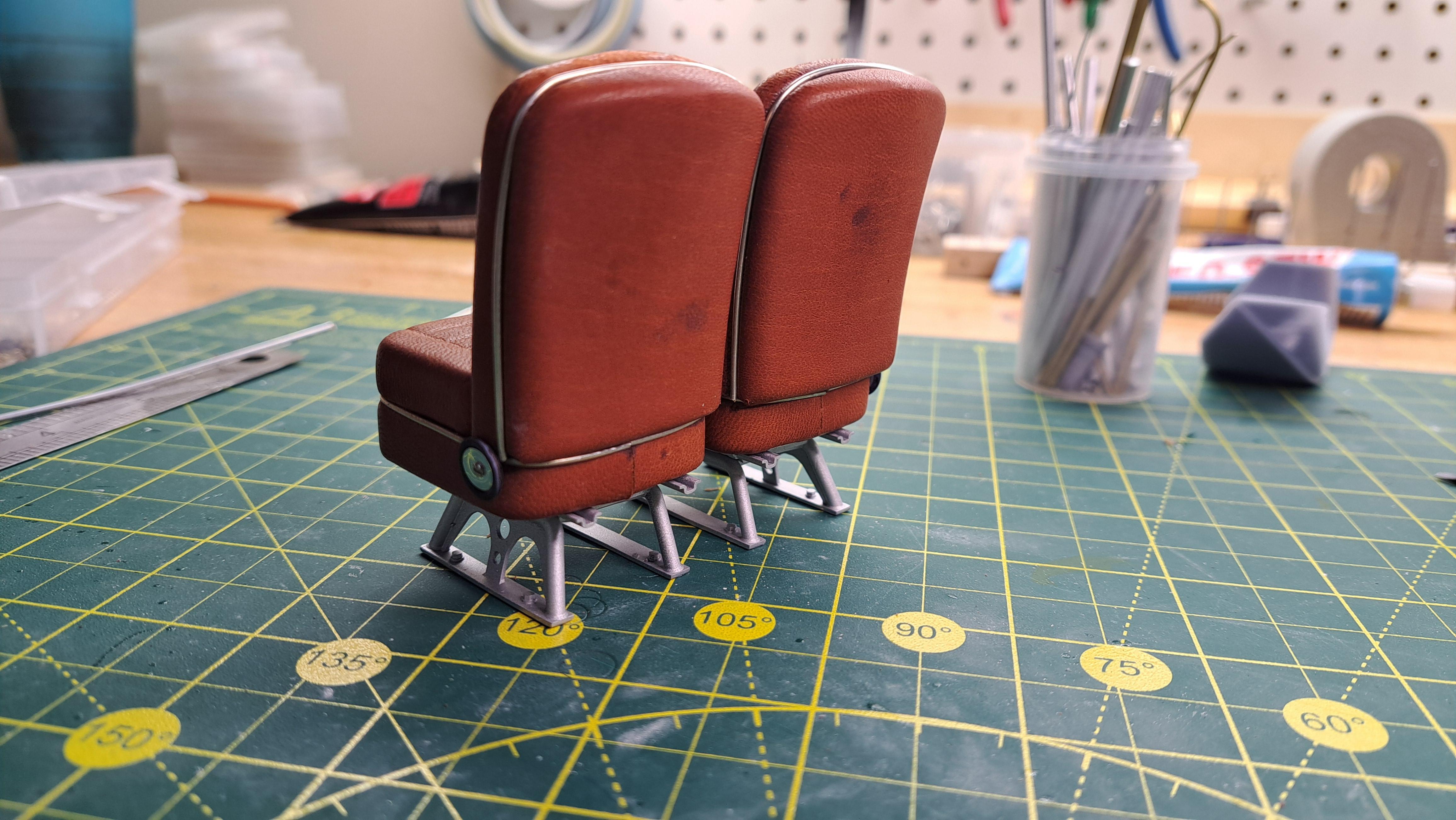
Thank you BDSchindler, No, I did not thin it. It's thicker than the red leather I used on the Bentley, .03" vs .022" but the seats on the hydra are a little bigger and I've learned a bit since the bentley so modeled the seats accordingly. I accentuated the pleats and added a few features to aid the 'tucking in' of the leather. -
Marvel's Hydra coupe 1/12 scale full scratch build
François replied to François's topic in WIP: Model Cars
Sneak peek, nothing is buffed of wxed yet.
-
Marvel's Hydra coupe 1/12 scale full scratch build
François replied to François's topic in WIP: Model Cars
Thanks !! I do try my best... -
Marvel's Hydra coupe 1/12 scale full scratch build
François replied to François's topic in WIP: Model Cars
I had 2 ugly grease stains on the back of the seats. I was able to clean the stains on tge right seat but had to replace the stained leather on the left one. While at it, I replace the Backrest fold pivot by folding lever. Looks more appropriate. Stained seats Repaired seats Old backrest fold pivot (don't like) New backrest fold lever
-
Marvel's Hydra coupe 1/12 scale full scratch build
François replied to François's topic in WIP: Model Cars
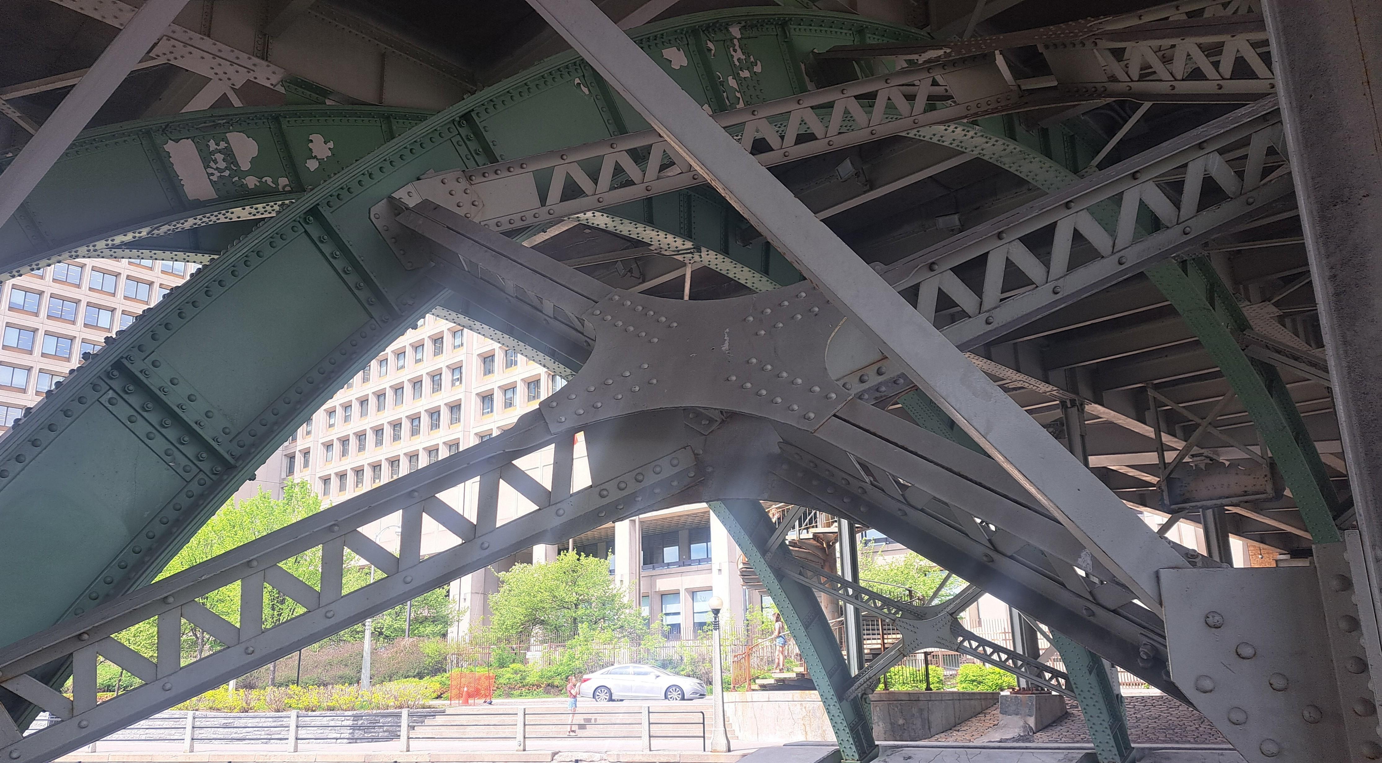
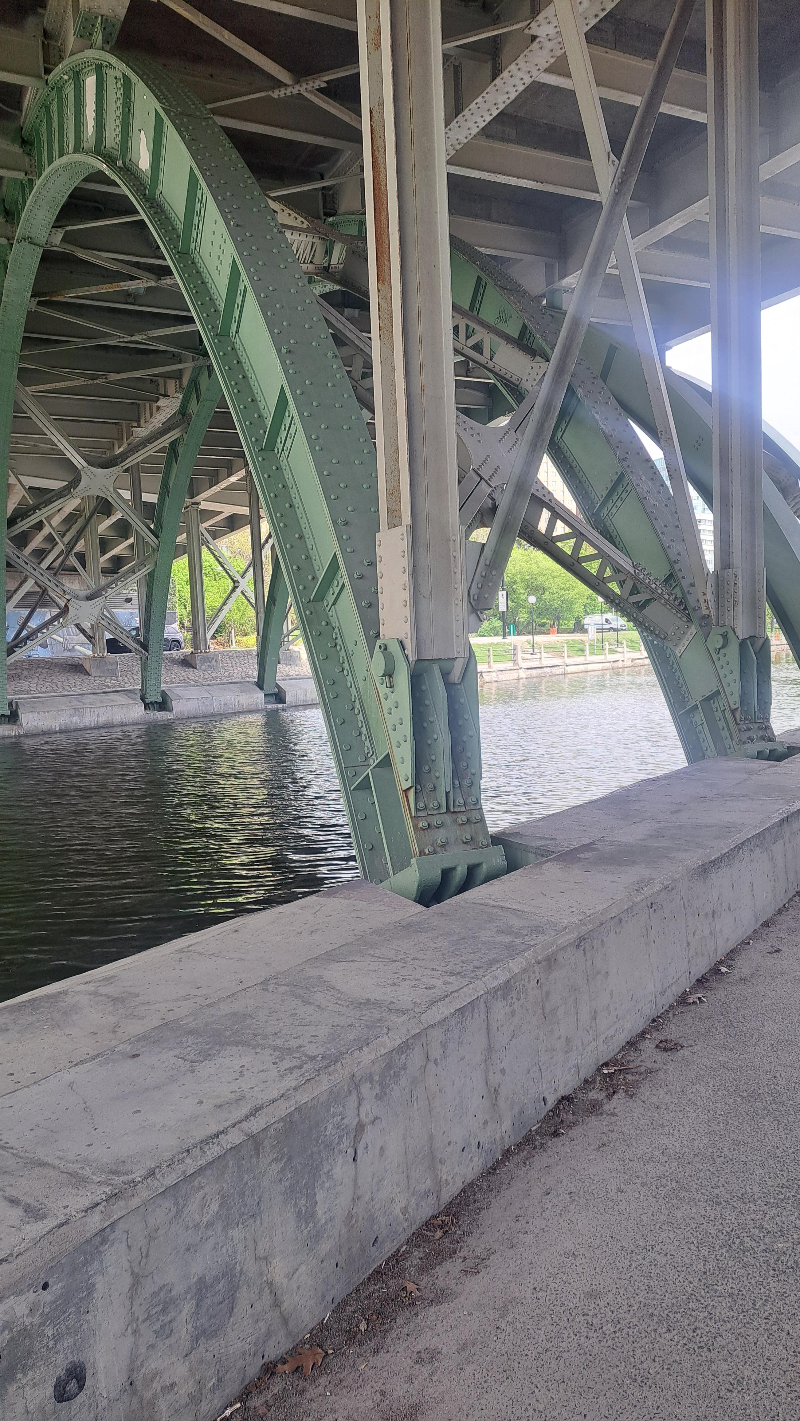
Now that the end is near, I'm starting to think about the display case. A few weeks ago, during walk, I came across a bridge with an interesting structure. I thought it might be fun to incorporate a few elements of this bridge in the display's structure. I'll also want to add so light fixtures of some sort. Here are a few pictures of the bridge to be continued...
-
Marvel's Hydra coupe 1/12 scale full scratch build
François replied to François's topic in WIP: Model Cars
And voilà the seats. Seat adjustment rails Backrest fold pivot Airline Style seat support structure and in place
-
Marvel's Hydra coupe 1/12 scale full scratch build
François replied to François's topic in WIP: Model Cars
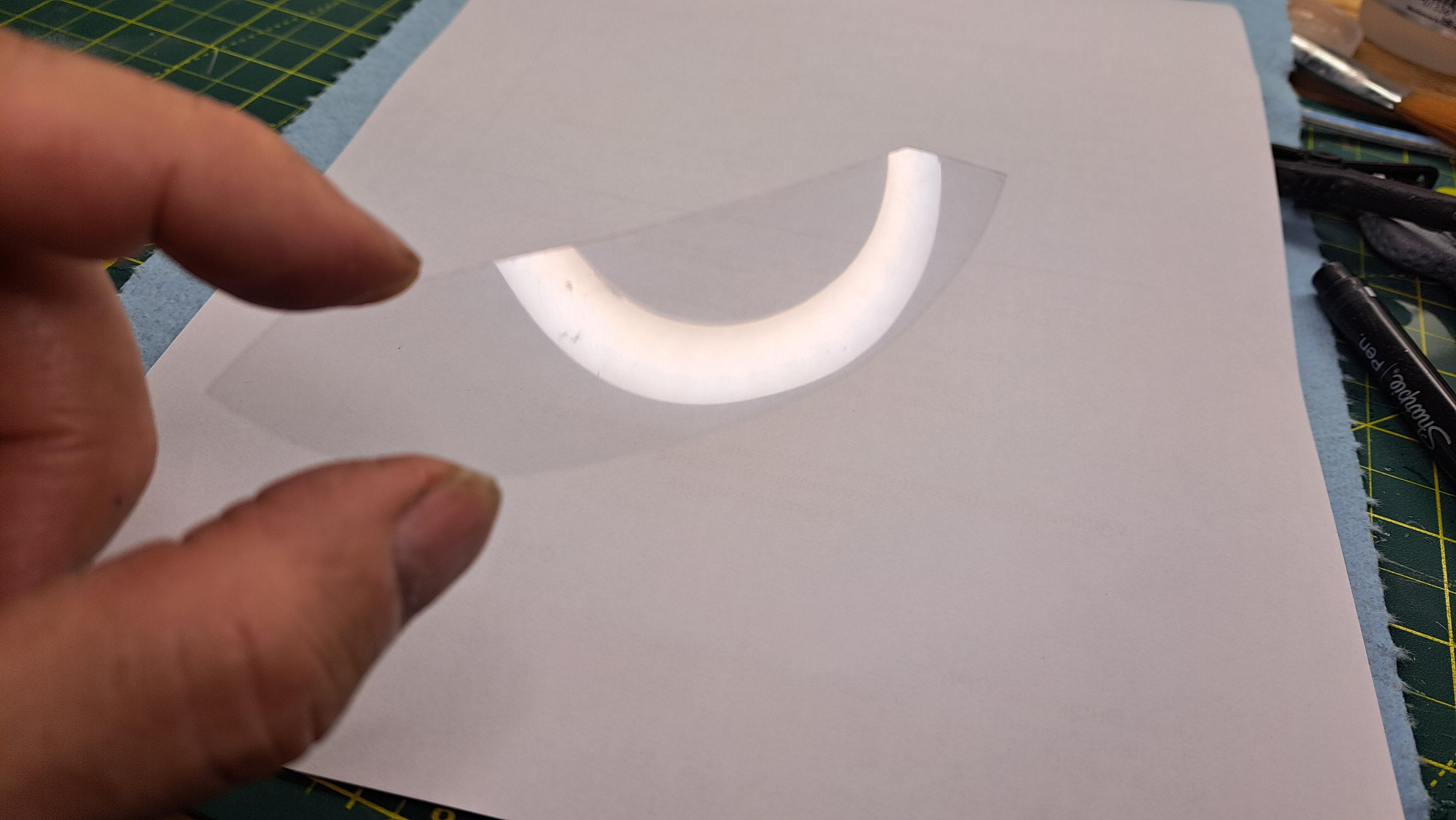
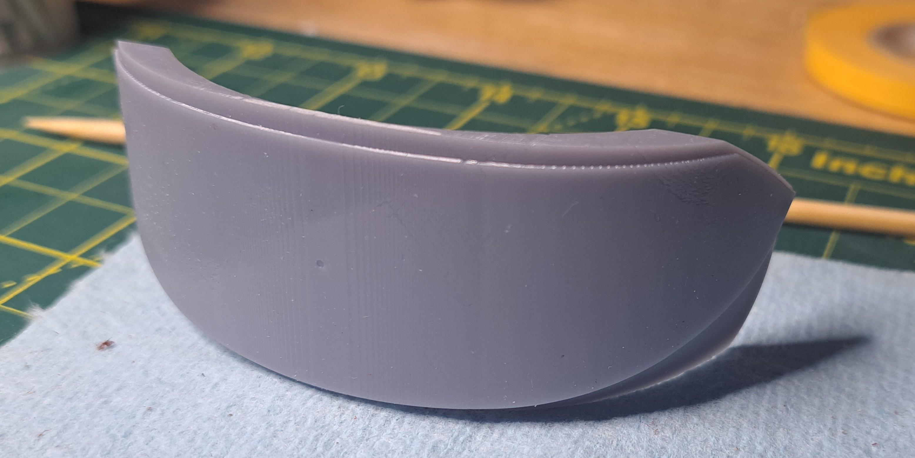
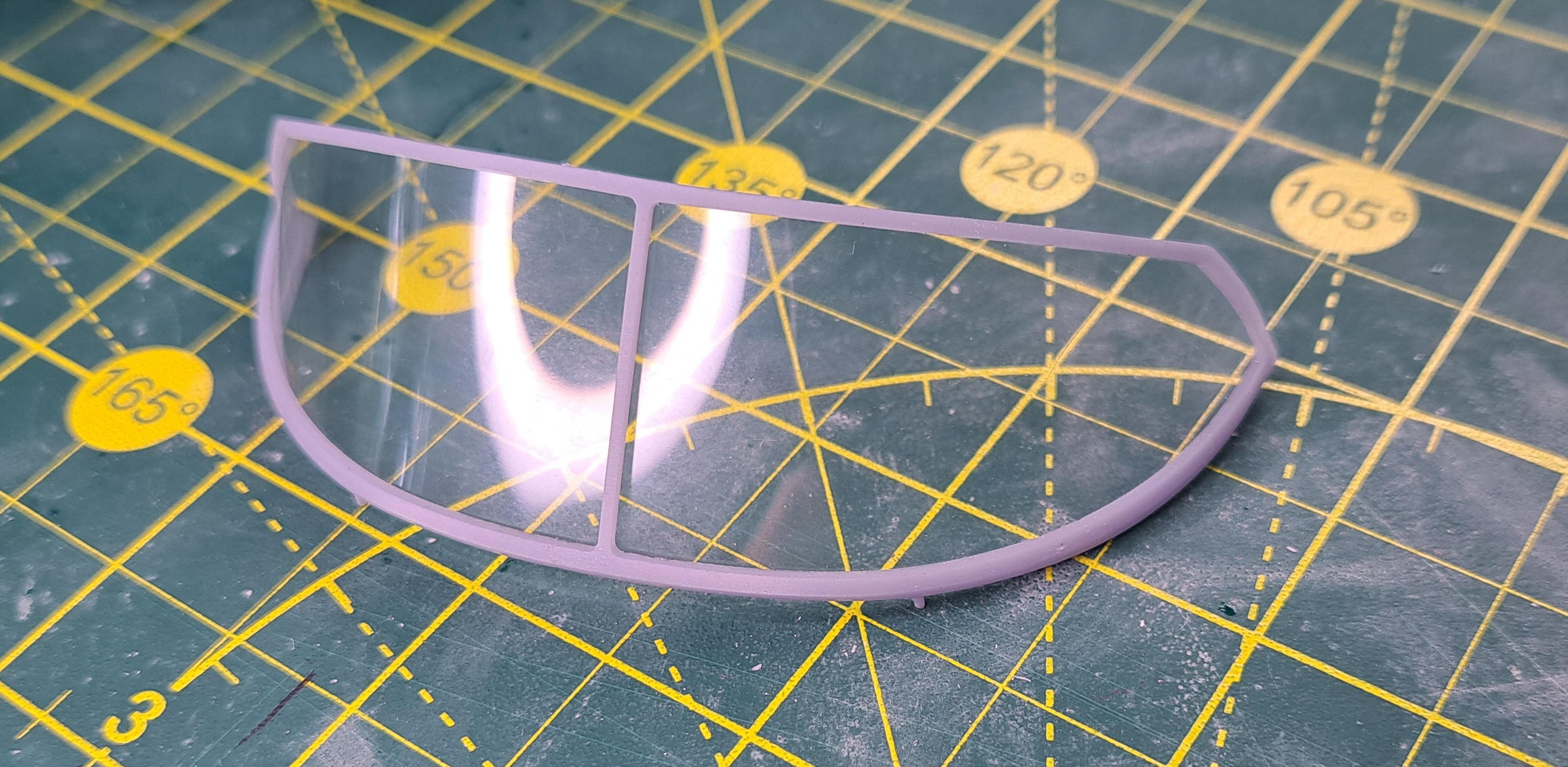
I did the windshield today. It's quite an odd shape to cut so I printed a template. To design the template, I used the 'derived component' command on my 3d modeling program. I apologize in advance to all you non-3d modeling savy readers out there, this will get a bit technical. Hopefully someone will know what I'm talking about, if not, well it will have been another good english writing exercice. What this command does is that it can sudstract one or more form (the cutter) from another(the raw material). The resulting 'derived' part is the difference of this substraction. In this particular case, I needed the curved shape of the windshield so I could use it to cut a clear plastic sheet to the correct shape. Now, I already have the windscreen frame modeled. So by substracting this frame (the cutter) from a larger form ( the raw material that the cutter cuts), I ended up with a derived part that has the exact shape of the windshield. There's one other maneuver that had do be done but I won't explain it because, well quite frankly, I don't know how to. Here are a few pictures to better explain The windshield frame The 'derived' part which is the difference between the frame and the raw form hence called the template The printed template Clear plastic sheet on template Windshield cut to size Windshield in windshield frame I also started to upholster the seats. The leather is nice and soft but a little thicker then the leather I used on the Bentley. It's a little harder to handle but the result is still nice.
-
Marvel's Hydra coupe 1/12 scale full scratch build
François replied to François's topic in WIP: Model Cars
So, all body parts have been clear coated (except for the 2 tool box lids, I have to repair the printer firts). The main body after clear coating Curing under dome. It was suggested that I cover the still wet parts with a box to protect from dust, quite ingenous Cured parts awaiting final buffing and wax Test fit of both seat on floorpan next up, leather covering of said seats
-
Marvel's Hydra coupe 1/12 scale full scratch build
François replied to François's topic in WIP: Model Cars
Thank you 64SS350, glad you like the project. I always appreciate positive feedback even when said feedback reminds me of errors I have made. I say this with complete sincerity. Thank you for the feedback. But, I feel I need to put a few things in context.This build as proven quite challenging on many fronts. From the design of a car from the ground up to mecanizing it at this scale. Plus everything is 3d printed. Those of you with engineering background in fabrication design will probably now the difficulties linked to a large quantity of parts (probably close to 1000, I haven't counted) working together. You might remember how the chain of dimension tolerance will effect the functionnality of a mecanism. I had to dig out my old text books on this, especially when designing the motor. All of this work is then "wrapped" in the body which, I know, is flawed in many places. I recently discovered (yesterday) that I have a major problem with my printer which accounts for some of these flaws. Being my first large 3d printed project, I'm learning as a go along. I know certain boby parts might have requiered more care in the pre paint finish, again live and learn. Like I mentionned in a earlier post, I was lucky to find 5 cans of the color I wanted from tamiya. I can't get anymore since this type of paint is banned from Canada (the shelves have been bare for many months since a replacement product seems to be difficult to find and other paint manufacturers can't keep up) so when I found these 5 cans I jumped on them knowing that I would be limited in the number of errors I could do. This is a huge model (25in x 8in x 4in) to paint so 5 cans is not alot. Sadly, some flaws were revealed only after painting. A more experienced painter would have known that, I do now. I have about 1/2 a can of paint left so I have to choose which body part to redo and I decided to redo the tool box lids since they really look crappy and are small enough to be painted with the remaining paint. I do believe that when everything is done, and given the scope of the project, it should look quite good. Keep on looking, the end is nearer then it was!!


.png.2c2f46010b2c7ce0aa0c5a198cd96dc7.png)