NormL
-
Posts
183 -
Joined
-
Last visited
Content Type
Profiles
Forums
Events
Gallery
Everything posted by NormL
-
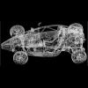
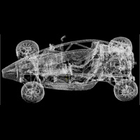
I was in the garage installing the louvered 1:1 Atom fenders and found some old model kits in the back of one of the drawers. I used to have this car and sold it two years ago. Mine was a 1965 ASA1000 that I had for twenty years, amazing little car. 97 bhp in 1965 out of 997 cc! Bizzarrini design, Ferrari manufacture. Anyway, I found two of these kits and finding them made me dig out and shoot some bad pics of my GT40 diecast. I posted the GT40 in diecast. I have made no additional headway on the model as I was working 1:1 today. I do have a personal goal to order a new print by Tuesday evening
-
I found the old 1/42 scale ASA's in the garage today and it got me thinking about this. It was a gift many birthdays ago and I do not know much about it. Amazing detail that is for sure. Less than good photographer that is also for sure.
-
I saw the 3D wheels that you did in a different thread. I am anxious to see what you can come up with as the combination of modeling and computer modeling skills come together.
-
Computer, .. no modeling, ... wait, they are the same thing!
-
Got the steering system finish. I am a little concerned about the gaps in the linkage, but, I would be more concerned about a fixed linkage breaking.
-
One print and it is done. I am trying to make a functional print and I am doing compromises to an accurate print to do that. Basically as you know you can print with a gap and if the gap is big enough the real printed parts do not touch. If you print fifty individual parts at one time that do not touch they can interact with each other. The sintered nylon is also not a dead solid if it is printed thin enough it has a lot of flexibility while still maintaining amazing strength. For instance, you can print coil springs that actually compress as a true spring should. That feature may not be unique to the laser sintered nylon, but, this is an experiment into how far it can be pushed. After the first print, I decided that if it could flex, maybe it could store energy also. That is where the ridiculous spring "engine" came from.
-
I got the rack to fit close to where it actually should. So happy now! I still need to add the spines and make the gear (the disc is a place holder)
-
I hope you guys are finding this interesting. The Atom guys quit posting a while ago, .. it is hard to tell if they are sick of it or are just lost as to where I am going. You can print in full color, just it can only be done with a slurry that is kind of like paper mache is what I have read. It is very weak Well I can't place the rack in the stock location as there is just not enough space to get the arms to the wheels. So I was thinking that I would place it forward of the feet bulkhead. Looks like it is running into the frame, so, below the frame I will try.
-
Mirror the "special" tracks and rails for the steering to the other side. It actually does not look as bad as I thought. I am going to go to a rack and spur system for the steering actuation. That is the only system that will fit and give me the length of travel necessary to actually steer. I am also thinking I can double up on the storage spring if I add a third shaft. Never too much power!
-
Ummm, ... shrimp Po Boy, ummmm Push the button! Hurry, push the button!
-
Pat, here is one to think about, .... bioprinting http://www.organovo.com/products/novogen-mmx-bioprinter , which is actually really cool, .... but then you have the home owner version http://boingboing.net/2013/01/24/howto-make-a-diy-bioprinter-ou.html Don't bother me honey, I am printing little people for my diorama! "but"... "they all look like you!"
-
How hard is it to get working steering in a 1/24th scale model with 0.5 mm gap minimums? Look at the attached and you will see how far I have gone to get it done. Using anything that resembles the stock attachments is too lose. This actually uses the slop to my advantage for up and down suspension travel. I have done a couple of motion sims and I am thinking this will work. Now the linkage! Atom Steering.pdf
-
I will definitely post the completed pics, good or bad. I think we are at the time that a hobbyist could use the technology, but, why buy a printer. Just use a service like Shapeways. If you need more fidelity than they bring to the table, then outsourced to a printing service that is a little more quality like www.moddler.com Wheels can be modeled to a very high precision and printed there. That was brought up in the 3D printing thread in general section. This can be done now, but, the cost will be very high, but, is it really? If you print 6 things a year their big expensive printers will do a better job and I doubt you will have spent as much as buying your own and maintaining it and in a year, your's will be obsolete. The user that brought it up was splitting the cost by printing one set and casting many to spread the cost, perfect use of the tech. As far as when, my cell phone does a lot of stuff I never thought that I would want and I am still not sure that I want. They came on very quickly. "he'll try to have you burned at the stake for being a witch" was what was said about you in my Atom thread. Fair warning, I may be big, but, I am wiry!
-
Pat, I am hardly a proponent of home printing yet. As I have stated before, the printing industry is changing too fast to invest yet. I did almost buy a Boeing cast off though. I am using the Shapeways printers, specifically their $950,000 laser sinter machine. While I would love to have one sitting in my office it would make the cost for my printing in the $25k range per piece, LOL. I am sure their deposit machines are much more reasonable, but, that is really their concern. Mostly what I do is use this for rapid prototyping and there are a lot of services for that. I haven't been able to beat the cost of Shapeways yet, even though some of their rules are very irritating. The more expensive badge to my door was $26.84 the other one is about $0.50 cheaper. We will see how good they look when they come back from Chrome Tech. The car they are going on looks stellar and they need to belong to it.
-
Thanks for pointing out that not everyone knows what an Atom is, LOL. You would think I would already know that as every time I stop at a gas station I get pummeled with questions. I changed the thread title so that it is more representative
-
Did you catch the tree where you can turn components off and on? That is my favorite part or maybe being able to measure. There are some really cool 3D Andriod and iPhone apps too. The one I use is Inventor Publisher
-
Maybe naivety on my part, but, I was assuming that Chrome Tech was using that process or better. I haven't had much luck with trophy people anyway. About a year ago I tried to get a point cloud of my car in crystal. That is what you see all of the time and I have the point cloud. Well, ... their computers are set up to take an stl file and convert it to a point cloud and they make what you want. I could find nobody that that knew their software well enough to just use the point cloud. Oh I heard, yes we can do it, but, no they couldn't. So I was left with modeling the entire car from a point cloud so they could take the model and make a point cloud Left me with a fairly low impression of their "technicians", at one point I was told that "we are just not set up for someone that knows more than we do"
-
They are badges for the valve covers of this
-
This is a Shapeways print and I cannot control orientation. It is also sintered and it sounds like you are speaking of an extruder or a deposit style. It is one of those base decisions, I chose the strength of sinter over the dimensional accuracy of the other two. For modeling, then yes an extruder or deposit style is probably better. For what I do, I deal mostly in sinter for strength and it helps that it is cheaper. i am printing a little 1/24th scale jack in a deposit style in the 2006 Ariel Atom thread and I fully expect it to be smooth. The heat issue is from the location that the parts will be sitting not the chroming process. They will be sitting on a 1:1 cars valve covers.
-
I went ahead and spent a little time on the 1/24th jack and took the joint gaps way down and basically refined it. I never did find the cup that goes in the lift plate, so, I just made one. The gaps were from the 50% reduction of the 1/12th version and were 0.25 mm and I took them to 0.1 mm The jack should actually work, but, you never know until you print it and try. Since I am doing 3D models, I decided to place a 3D pdf's instead of a lot of pics. If Harry or another mod has an issue with this, just tell me and I will post pics instead. 1-24th Jack 2013-01-24.pdf
-
Well, I don't have any chromed plastic sitting around ... So these basically are the test pieces. I do believe that if I did have any it would have been styrene anyway and i would not have ended up with a true representative test. The Alumide is heatproof to 172°C/342°F according to their website, so, the base material will be fine. We will see regarding the chrome A operable cooling system should be keeping the base engine in the realm of 180°f-190°f and the cylinder heads do get hotter than that, but, the covers will not even get close to 342°. The engine is basically a 500whp n/a SBC that will not be worked very hard in a very light car. Yeah, I should not have sealed it ... that one is on me. Thanks again for your input Pat!
-
Well I thought long and hard about it and decided that the heat resistance of the chrome material should be fine and there is only one way to be sure. I also looked long and hard at the layering lines and decided that they were part of the background and not the message and might actually look better with the radiation from center. I shipped it off yesterday. I emailed Bob and got an email back stating why did I "Future" it??? Oh well, we will see, I may be paying for some Bob time to un-Future it ....
-
Caterham's are such cool cars. Just a little too claustrophobic for me I guess Your commitment to detail and the ability to accomplish it is outstanding. I do enjoy this thread
-
I have two scanners. One is a time of flight and one is phased based. The TOF is +/-1mm within 350 feet and the PB is +/-1.5mm within 75 feet. The difference is collection with the TOF being 50,000 nodal points per second and the phased being 508K pps. When you take the first sigma mean from a cylinder containing 150k points it is pretty accurate. The Atom's main tubes are splined in two directions at the same time and did take me a moment to figure out how to model correctly. Mine are BIM (building model) scanners and the short throw scanners are much more accurate
-
I am resigning myself into having to add an idle shaft. I can't increase the size of the gear that resides on the drive shaft as I am as close as I can get to the frame. The gear ratio as it is now is too much for the spring and I thought I would end up here and here I am. I can drop another shaft in below the spring shaft and actually have a choice in gearing. I am also going to add at least two support webs between the now three shafts hard mounted to the frame I did start the steering redesign today and scraped and restarted two more times. I am thinking I have it now. I have several more hours before I can shoot a screen shot.