NormL
-
Posts
183 -
Joined
-
Last visited
Content Type
Profiles
Forums
Events
Gallery
Everything posted by NormL
-
3-D Printing is now affordable
NormL replied to Darren B's topic in General Automotive Talk (Trucks and Cars)
3D chocolate printing is my favorite. Edible car models, when you get tired of them you can get fat... -
I love the plastic Jesus, made me laugh out loud. New to the forum myself, so, I didn't know if every fifth model on here had a plastic Jesus and now I know better. I applaud your originality.
-
Thanks for the feedback, my wife has been shaking her head all day. I have my Craftsman 2 ton jack sitting on a shop towel on a coffee table in the living room. She drew the line at the kitchen counter .... I must say the cone was much easier to measure and make all the moving parts move.
-
OK, finished. The same pic's work for the 1/12th and the 1/24th as they will use different materials. 1/12th scale in WSF and 1/24th in FUD I don't know where my tray is for my jack. I use the jack for the Atom and I can't get it under the car with it on. I must have placed it somewhere I could not forget. I am going to have to find it as my other cars do need it.
-
I am not setting any speed records as i am watching football mainly, LOL. I still need to make the two sides stable with each other, create the arm, the spring and the handle stops. The gaps on this 1/12th scale version are 0.5mm. I wish I had some of your metal skills as adding a few shims and this would work quite well.
-
Well I decided that my diorama needs to be 100% printed. So I got started during the Seahawks game, ... sad right now. Anyway got the easy stuff the outer frame and wheels done.
-
OK, stupid question, ... does someone make things like pneumatic jacks and jack stands in 1/24th? My desk diorama needs more stuff. I was thinking I would print a working jack for the frame, but, my measurements tell me it would have to be 1/12th scale not to have a lot of concessions. Just a static thing at 1/24th. If not, I will go ahead and do the 1/12th and then scale it down, I kind of like the dual articulation point challenge to make the jack pad stay flat.
-
Staggered. Stunning work, much respect
-
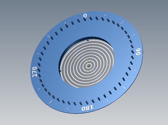
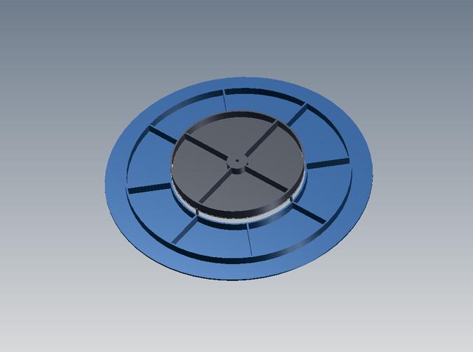
I was asked to create a 72 spoke version. It is here http://www.shapeways.com/model/866350/wheel_tool_72_spoke.html?key=d634302ea84addf6f57a7b54cd2a7449 Do I need to add a center plug on spues for several sizes of tires posts? i.e. a 1" stick in several diameters with a 2 mm inserts for the center hole. If so what diameters?
-
-
No prob. I was just so impressed by what he did. He didn't leave any dimensions, so, I kind of guessed at the holder he was using. I made the overall 6" with a 3" main hole and 1mm thick and of course 48 pins 2mm in diameter spaced at exactly 7.5°. 1.5mm pins may have been strong enough, but, I wasn't comfortable at that size. If you always tie off the same side of the pin, the pin width does not matter anyway.
-
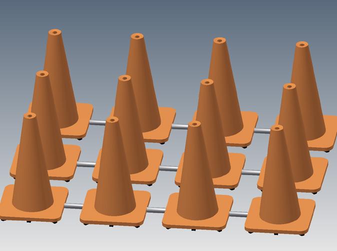
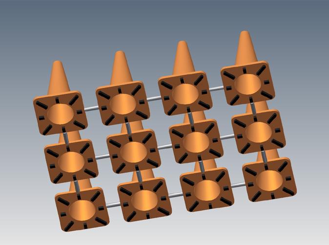
I designed some cones to go around my model once I get the final print. This will annoy the people in the office more than usual, LOL. Next time I print I am going to order a set. So, I guess I am going to paint after all. http://www.shapeways.com/model/865938/cone.html?li=my-models&key=d690fcd865d08a4308707f72608c0ac3

-
I'm sorry, I thought that was well covered by the explanation in the first and third posts. It is his idea, I just made a printable jig.
-
I thought this would be a very nice thing to print in 3D. A helpful tool. Unfortunately, pricing is based upon the cost per cm³ and it has to be strong and functional. So it ended up being a little, OK twice as much as I thought. Basically $40 for the price they are charging for WSF. Obviously that will go down, but, today $40 ($1.50 design fee to me and so I can track if someone orders one) I went thought the exercise, so, I am leaving it up on Shapeways. http://www.shapeways.com/model/865746/wheel_tool_48_spoke.html?key=3c2a1b6b3feb4a587dfe24225486094d I sprued the inner and outer pieces together and they will have to be x-acto'ed apart. The inner and outer face have exactly the same radius as I am assuming that a tight fit will be needed, so, some sanding for an exact fit my also be needed. I have no idea what the nail diameter for the center of the inner piece needs to be as I am sure that varies with the model wheel being used, so, I left a 2mm diameter hole
-
Too much is being made of 3D printing, at the end of the day, it is just another tool in the tool shed. Will it replace injected plastic? I am not seeing it yet, as the cost will never be less. There will be those that use the tool now and others that wait to implement, regardless it is here to stay. Richard, I think you did hit the nail on the head as there is a substantial learning curve to get to the point where you can design and entire car and print it. The learning curve is much less for parts and that is undoubtedly where it will blossom. You mentioned wheels. I did the Team Dynamic Pro 1.2 wheels on the Atom in about an hour. I went to the scan cloud and took a cross section of one spoke of the twelve, just a jpg screen shot. I took that jpg and embedded it into a CAD program and traced the outline. I then went to the Pegasus tires that I could source and determined the dimensions the wheels had to be, this was with blatant disregard to scale as I was matching something. I then scaled my spoke cartoon to the radius of the Pegasus tire. The cartoon was then revolved 360° into a 3D solid that you would recognize as a wheel blank having the shape of the wheel without any cutouts. Back to the scan cloud and measure the cutouts and apply them to the wheel blank and now it is really starting to look like the wheel. However, ... more compromise time, ... the spokes have to be a minimum of 0.7mm to be printable in WSF and that can't go on for very long as that does not dissipate printing heat. I decided that since they were holding the weight of the entire model, I would be cautious here and made my minimum 0.9mm instead. So the net effect is the outer points of the wheels are compromises as are the proportions, but, they don't look that bad. I then just went to the car with a verier caliper and measured the depth and other attributes of the lug areas and did those cutouts too. Fillet the edges, done. OK, a person working out of their house is not going to have access to a scan cloud, so, you end up throwing a straight edge over the wheel and measure the out and downs, ... same effect. Maybe it would have taken an hour and a half without the scan cloud. This is all something that could have been done in the open source Blender for free. My point being the design of parts is here now. Car bodies, that is a different issue and requires that you have the scan cloud or you are willing to ultimately compromise on reality. As far as the porosity and other printing issues, let's go back to it is a tool in the tool shed, ... learn how to work with it. The printing manufacturers are not going to pander to you for a while as they have bigger more lucrative fish at the moment. Sealing it cannot be a deal breaker. Having to sand it smooth, again that cannot be a deal breaker. I am into the challenge of the design, so, I am going for something different.
-
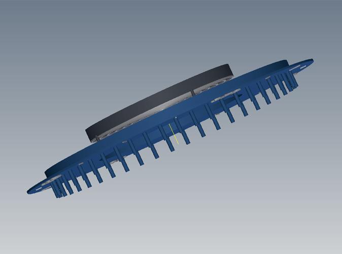
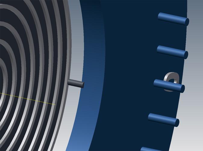
Since I don't paint or work with models, my opinions on applicability are fairly useless. I can tell you if I was trying to do an accurate representation, I would not be utilizing just one printer. For true representation with current tech, I do believe you have to use several methods to achieve the goal. I would be using WSF for the main body and structure due to cost and strength, I would be using FUD (Frosted Ultra Detail) http://www.shapeways.com/materials/frosted-detail for detail glue on parts due to the very high detail but highly brittle. FUD is a deposit style of printing and I have seen some extreme detail from this that I would find hard to believe would not meet detail standards (this was not a Shapeways print). Shapeways deposit style does have some great detail look at the tiny Atom next to the penny on page one of this thread, but, I have seen the flawless repeat of the detail of the face of a coin. I would love to have access to an SLM machine for sintered metal, the detail and strength being another big bold step, ... i.e. I think might still be NASA only. Subject change ... Getting bored awaiting the model. Here are some detail pictars of how I am envisioning the systems working. If it works, very cool! If it doesn't ... The idea is that you would push in the rod by the tire which in turn pushes a plate and shaft to the right. The drive shaft gear is on the shaft and will be forced into contact with a very large granny gear on the storage shaft. Dragging the car backward will now "load" the spring. This will spin the storage shaft and start walking it to the left until a pawl engages the top lever and the shaft will not rotate anymore. This should now be sitting in a locked state until the top lever is activated. If there is enough flexibly in the plastic printed spring when the lever is released it should spin the drive shaft and the car should move forward. It may not move, dribble forward or do a burn out, ...lots and lots of ifs ..... I also got a feeling reading the 3D printing thread, that some of you are awaiting that printer for your shop before you jump in. Tech is changing way to quickly for any printer purchased not to trounce any laptop in devaluation. That is why I use Shapeways, their 900K laser sinter machine is fine, I wait a week but I don't get 84 easy monthly payments. Otherwise you may be waiting a while and as I said above, several different printers may be necessary to do what you need.
-
I didn't post the stuff that went into making the first print here, well as I wasn't here then. If you are curious about it prior to what I show here you can see it on AtomChat http://arielatomchat.com/forums/thread1178.html A little more incite and some bitching.
-
Oh, you mis-understand, I was always going to finish the working model come hell or high water. That's one of those "can I do it?" things. Besides I have way too many hours into it to just drop that aspect. I guess I was trying to find out if others were viewing that aspect as cool as I do or they were more along the lines of "yeah that's cool, but, when is the model coming out?"
-
OK, let me rephrase the question as modeler's will always answer accuracy to the question that I asked. I am enamored by the engineering, so, I look at it a little differently. As your first 3D printed model base, would you prefer an example of how far it could be pushed at the time in a single print (movement) or would you still prefer accuracy?
-
I tried to find these comments last night on the forum and was unable too. I did see a thread about 3D printing in general that did bring up some good points. There are always compromises and with current technology you just cannot make a perfect reduced sized model, concessions will be made somewhere. We just cannot print thin enough and still have strength although I am watching what is happening with SLM with high interest. It was brought up in that thread how thin body metal is went reduced to 1/24th, which is true and a great example of a concession. For me all of the frame rails and I do mean all of the frame rails are a true 1/24th scale, but, the suspension joints are major concessions. Now if I go back later this year and say design the lower tub for the car I will have no choice but to hug the frame. My minimum design width for WSF is 0.7mm or 16.8mm true, that has to outward as I will have no choice. We are talking about a concession that would be very hard to see with your eyes, but, I will always know it is there. Another example is the steering on the car. The steering wheel is in its exact location, size and tilt, but, if I mimicked the stock mounts it would break the first time someone touched it. I was designing for working steering so the shaft is too big, the steering holder is not even close to stock, but, I did maintain the stock geometry. This leaves me with a question. When I walk away from this project, I will leave this model on Shapeways for people to print for themselves. My journey is for a working model exercise. When I leave it, do modelers want me to mimic the stock suspension and steering (still leaving it strong enough to sit on a shelf) or would modelers want the working model, ... curious?
-
This design is to the Shapeways design standards for White Strong and Flexible (WSF) http://www.shapeways.com/materials/strong-flexible WSF is a laser sintered plastic that is 100% nylon, so, most anything that you are used to will work. The issue will be a laser sintered plastic is left very porous and really should be sealed before painting. It has a rough course texture and just absorbs paint. When doing the fenders I found that I could be very rough with it. I had printed each front fender as 12 pieces that I glued together (this is because Shapeways apply idiotic length rules for long 3D objects). I used super glue to glue them into shape and the pieces absorbed a ton of super glue. I then took the fenders and bondo'ed them and sanded any imperfection out. I also used the bondo on the back side to make them strong enough for casting. Primer to 400 grit and cast. WSF is very strong if the part is engineered to have internal reinforcement and if printed thin enough very flexible, just a great material. I have also found that heat absorption ridges need to be strategically added to longer prints
-
Learn something new every day. I have never heard of Indycals before. Before a couple of months ago I had never heard of local motors either. I have been posting in their Ariel Atom headlight thread though.
-
Ok, I understand your point. Back in the day, .. OK, the '60's!, ... when I was making models I was amazed at the accuracy of the models produced. I was just a kid and didn't get the high dollar stuff if there was any, I was comparing Revell, AMT, Monogram and my favorite at the time IMC. I now, of course, know they were not as accurate as i thought and were the result of painstaking hours of measurement and drafting. They were amazing for what they were. The idea that a strict proportional reduction won't look the best is preposterous. I have had to oversize the joints and a few other things as concessions to 3D printing being fully aware that buy doing so it would hurt "the look". You are correct, the manufacturers should be utilizing the best tools at their disposal.
-
OK, there has to be history to the sarcasm. What am I missing? Sorry, Rob, you got in before me ...
-
I knew some of the Shapeways faithful would show up! I forget they have forums too.