Cato
-
Posts
2,674 -
Joined
-
Last visited
Content Type
Profiles
Forums
Events
Gallery
Everything posted by Cato
-
Arrrgh... I've taken many steps back and none forward over the last several days. Remember the trunk lid? A few compound curve seams were showing. Well couldn't live with it. I was going to make a trunk rack to 'disguise' the flaws, which is a lame thing to do. Not my style to cut a corner that badly. So plenty of Bondo, paper and time and I got it as perfect as it can be. NOW I can live with it. AND I'm going to make a trunk rack too, a marvelous chrome detail if I get it right. A heartbreak caused me to go the whole nine yards with the window frames. With all the door mock-ups, a 90 degree corner split open on me. I doubled down - remade each leg of both quarter lights from new; no repair botch. Started with a new plastic template - more accurate than the old. Made a new 'solder block' (for the inside corners) to match the template perfectly. Today I carefully cut and mitered (perfect fits) them all and drilled their plate holes. I discovered the two old ones didn't match each other exactly which is why I went back to square one. REALLY aggravated myself because I THINK I take care when I make things but see some things are slipping by me. At least I won't have to look at errors each time I look at it after completion. Also stopped horsing around and ordered a new Weller 40 watt solder iron; realized my 30 year-old Craftsman is down to the nub. Trying to do jewelry with blacksmith tools. There are lessons to be learned as you go along. More, sooner...
-
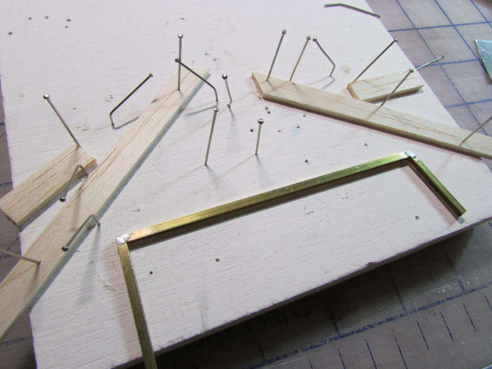
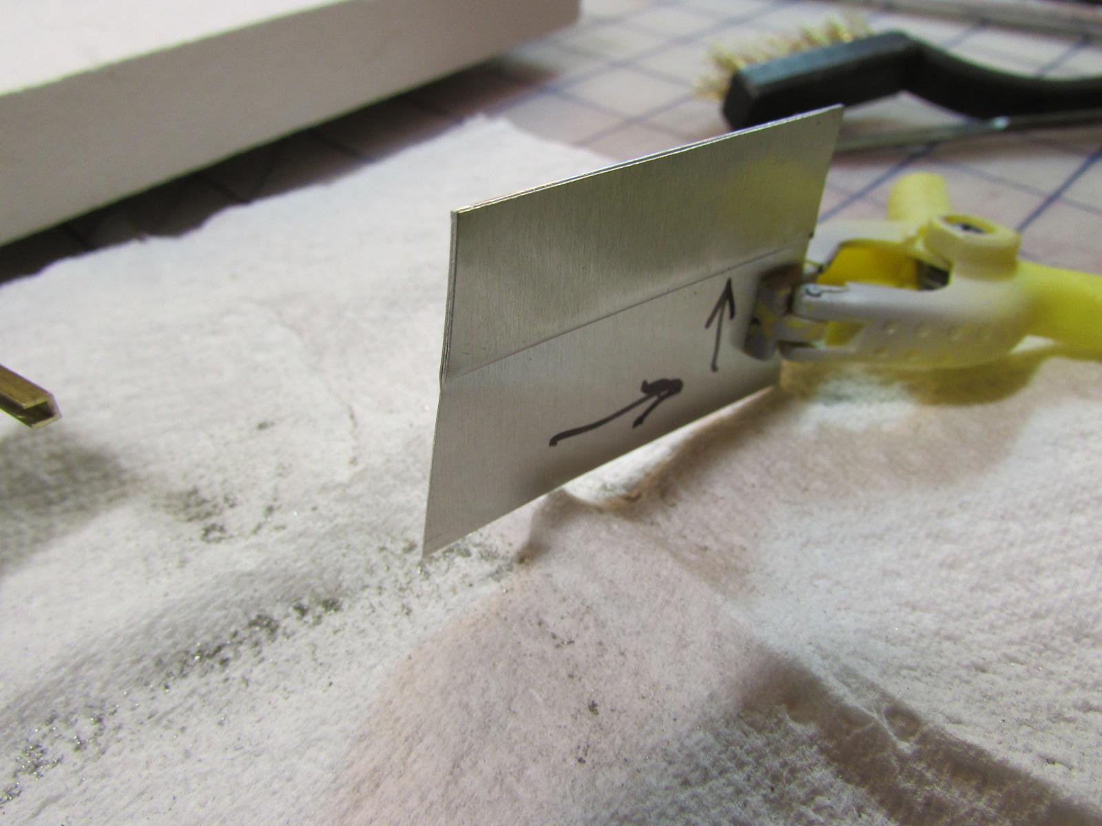
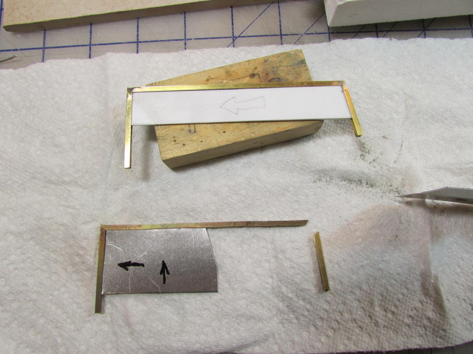
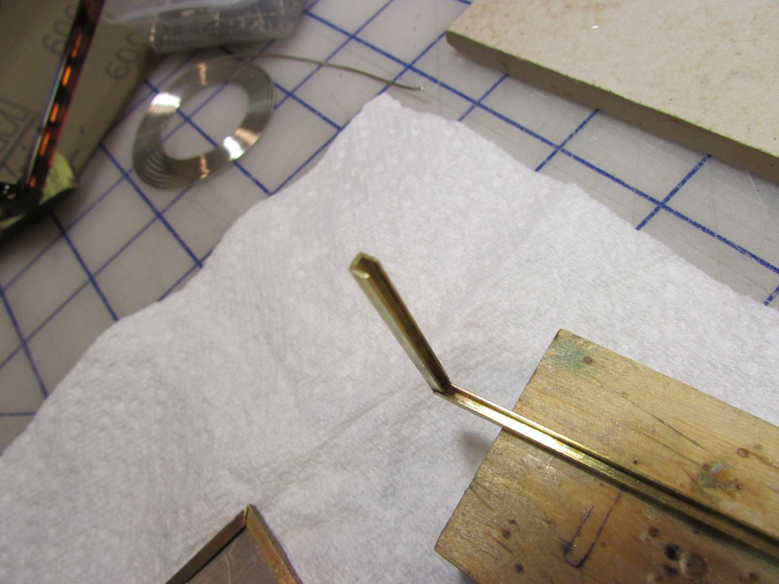
Here's where we're going... Today, the biggest accomplishment was figuring-out a system. And I did; shown is the miter cut 3/32 square channel for the window frames. Jigged, pinned and silver soldered cleanly.The problem being to solder the corners cleanly and keep silver solder out of the inner channel corners. BY FAR the key to this operation is to keep the channel corners clear so your glass fits. After a lot of experimenting the answer was baking pan ally, folded, cut and bent to fit comfortably into the corners. Silver solder won't stick to it. Worked a charm; no glop inside the corners which the last shot attempts to show. Note the lower blocker has the rear edge cut to match the slope of the rear of the glass; you want no gaps inside or you'll get solder. With just a little file and 220 work the corners are crisp and clean. And the original plastic template fits perfectly as shown. Plenty still to solder and dress but much relieved I've got a reliable system. It took me days to clear the channels in the 'screen frame using folded tin foil (boo) but this took 3 minutes to join and 5 to finish dress the corners.. The sooner I finish the sooner off for chrome; I'm excited to see the 'screen frame and running board strips come home soon. I'm also planning a chrome accessory which will be another soldering adventure... The pros may do this with far less effort and different ways but there are other ways to skin the cat. I'm satisfied the result will be hard to tell from a pro's work. YOU CAN DO THIS; if I can, you can. The look of chromed windwings and partially lowered side glass adds a natural and elegant touch to any Rolls and some of the other Pocher Classics. And better men than I can actually make these things pivot out and lower but my train stops here. I'm OK with that... EDIT: The pictures loaded in the opposite order than I loaded them. Dunno why. I HATE trying to get professional results with this 'progress'.

-
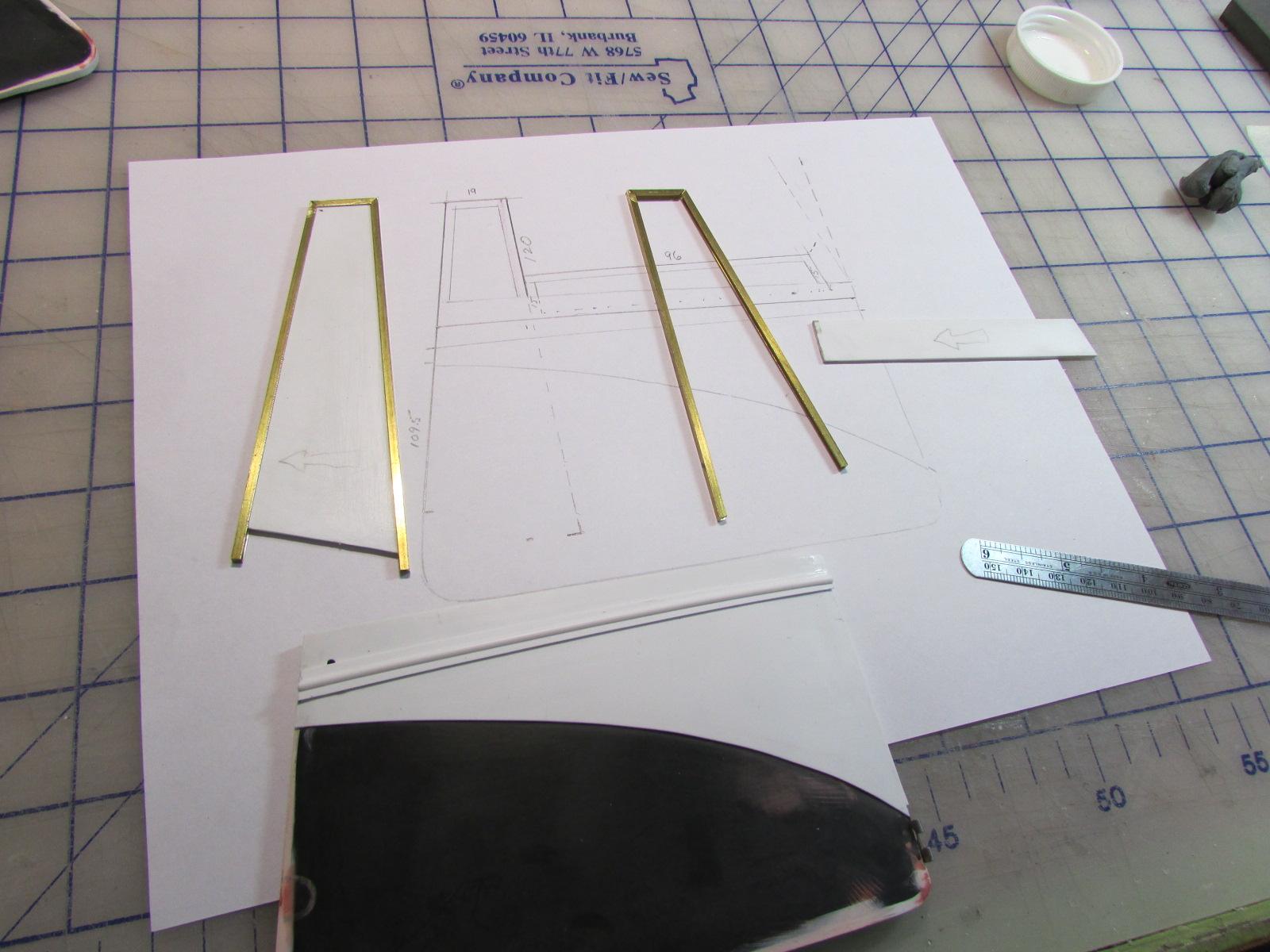
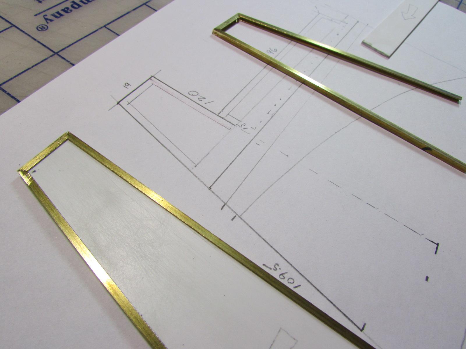
Return to work... After a vicious 10 day bout with what was probably influenza, it's good to be able to accomplish something. Although I had begun the hood just before illness, I was interrupted by the running board strips. Now that the 'boards are done and the strips are out for chrome, I've ordered some brass to correct the hood hinge. While waiting for that, I decided the doors should be finalized. To do that, I need the side window brass frames. The latch mechanism will go under them within the doors. So some time drawing up for templates and making them from .050 was done today. Then, cutting the channel legs on the bandsaw and sanding the mating angles on the disc sander. The front edge is not 90 degrees because it follows the angle of the windscreen. The back edge is 90 but I found it safer and easier to sand the angles of each adjoining leg to mate better than sanding 90's. Got the windwings done today, tomorrow the partially lowered side door glass. Soon a big time soldering session.
-
Could be done same as I did my Rolls burlwood; printed image on photo paper. Copy and save this image: Enlarge to your needs, print on quality glossy photo paper. Cut with scissors or knife. If desired coat with clear acrylic spray. If you don't like this one, there are thousands more on line. If you don't like the result, it cost you nothing. No one will know it's paper in place on the model.
-
Very kind of you Dennis and I'm glad my work inspired you restore and improve your old kit. They are sad if left to deteriorate. Please post a WIP here. There are several of us Pocher crazies with projects in the works and therefore a wealth of information. I'd be glad to answer anything I can so don't be a stranger. There are many fine upgrade parts in the aftermarket which are frequently discussed. I'll be back at mine soon I hope; as soon as I get rid of the flu.
-
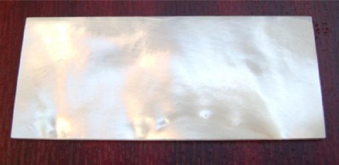
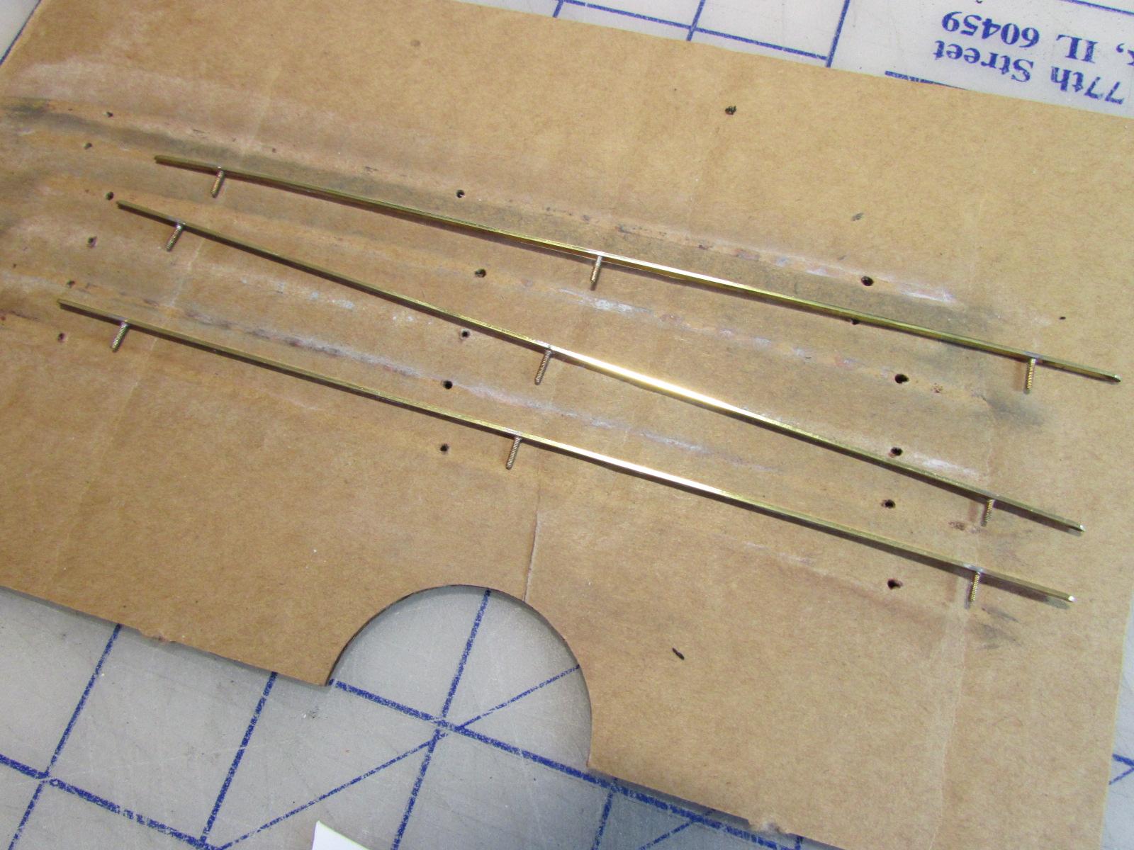
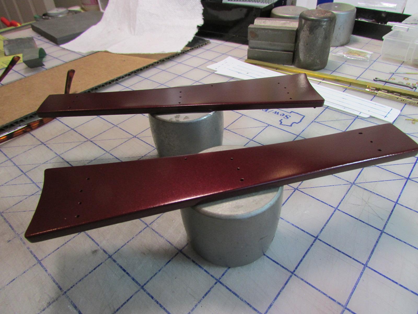
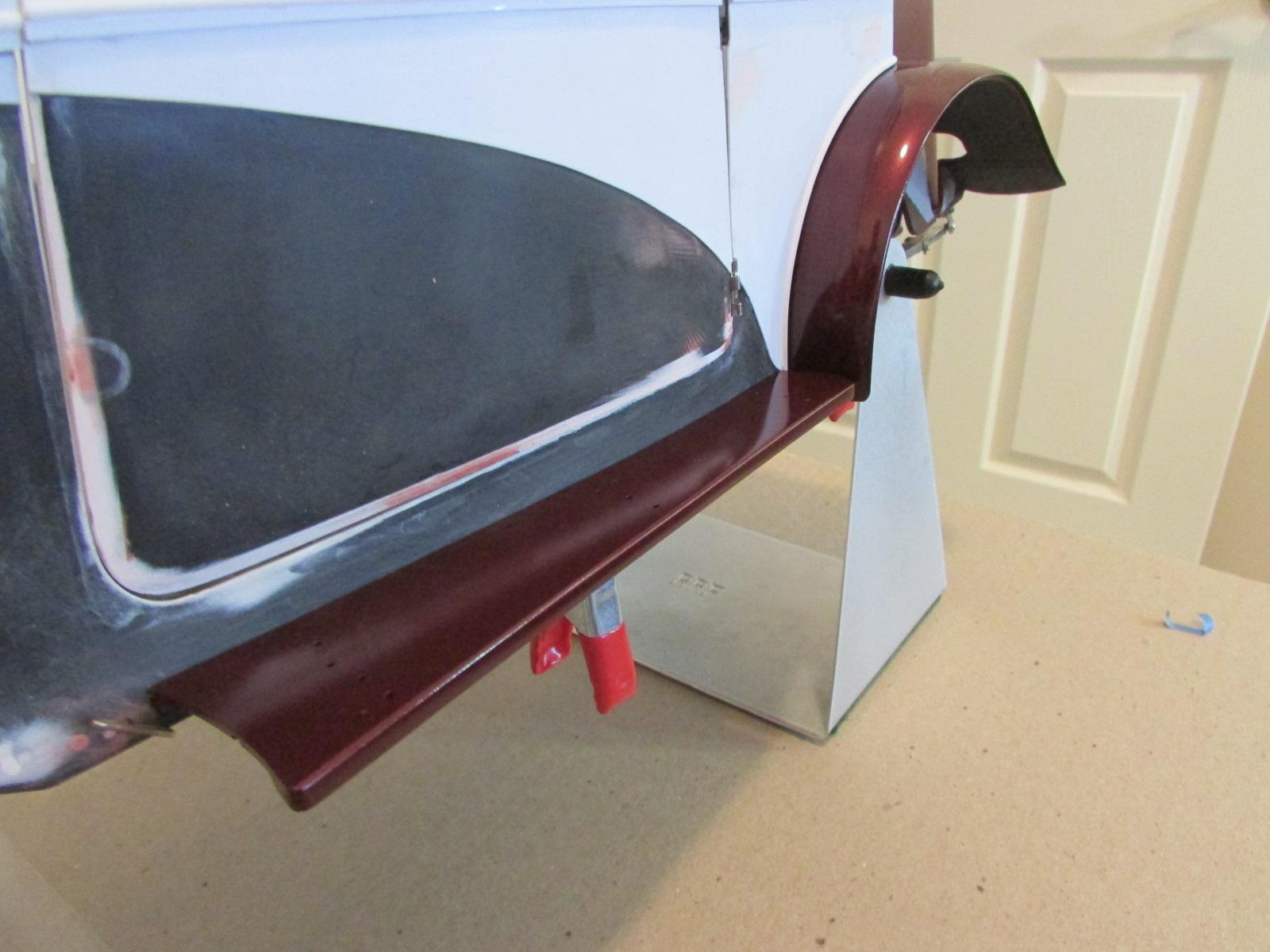
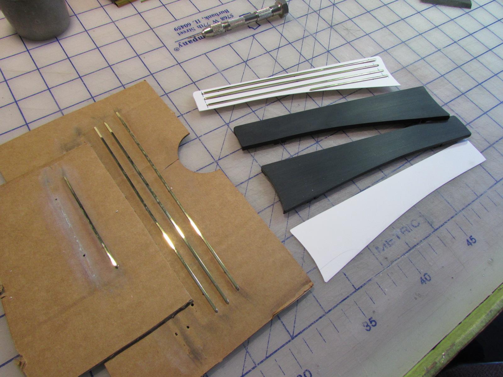
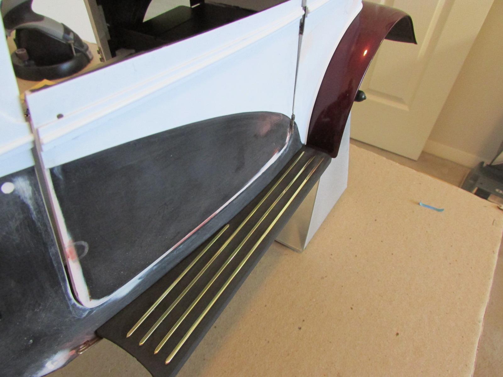
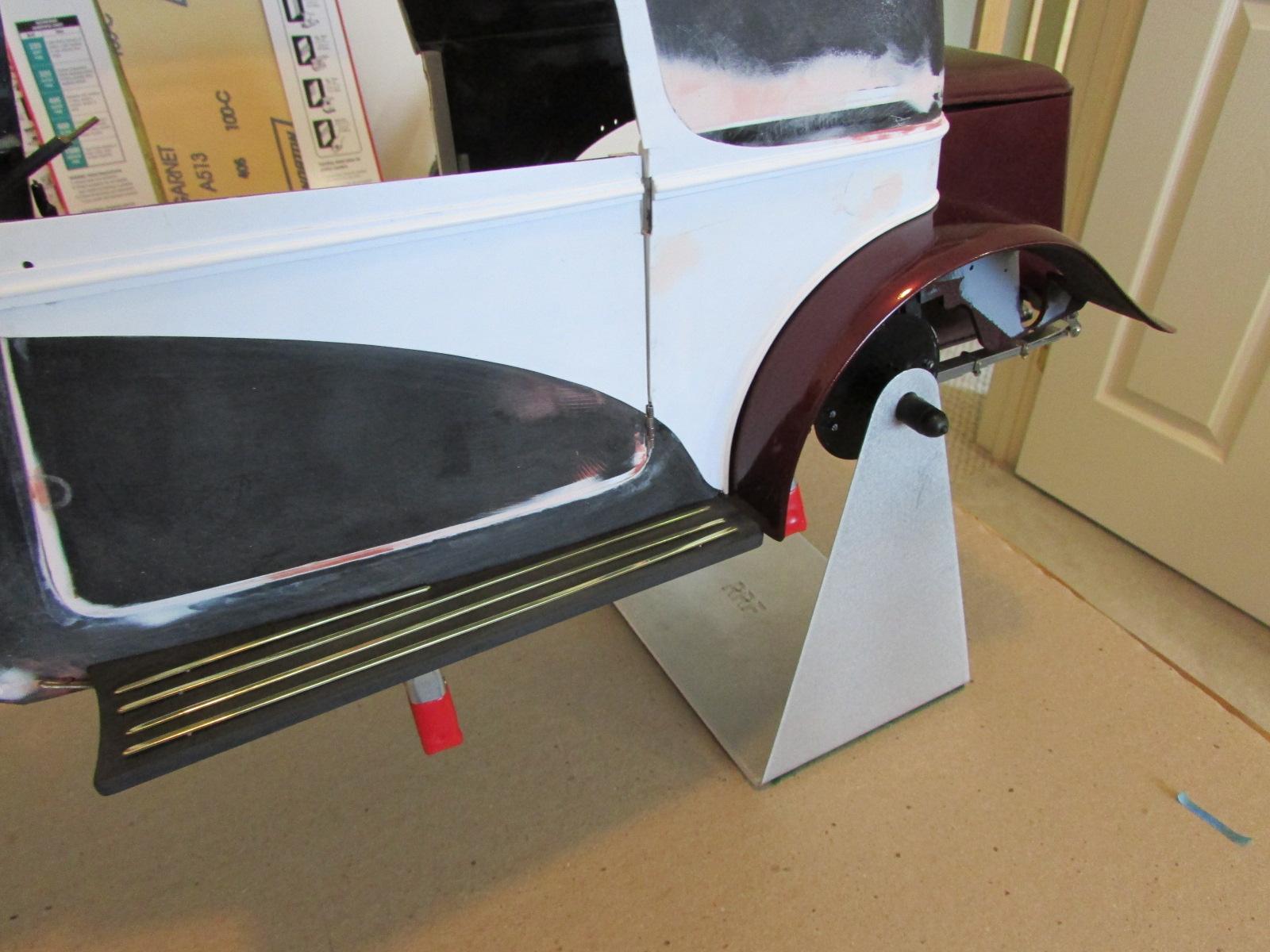
Forgot... This is how the strips came from Dave Cox. And today, the running boards got their color. Tomorrow the clear.
-
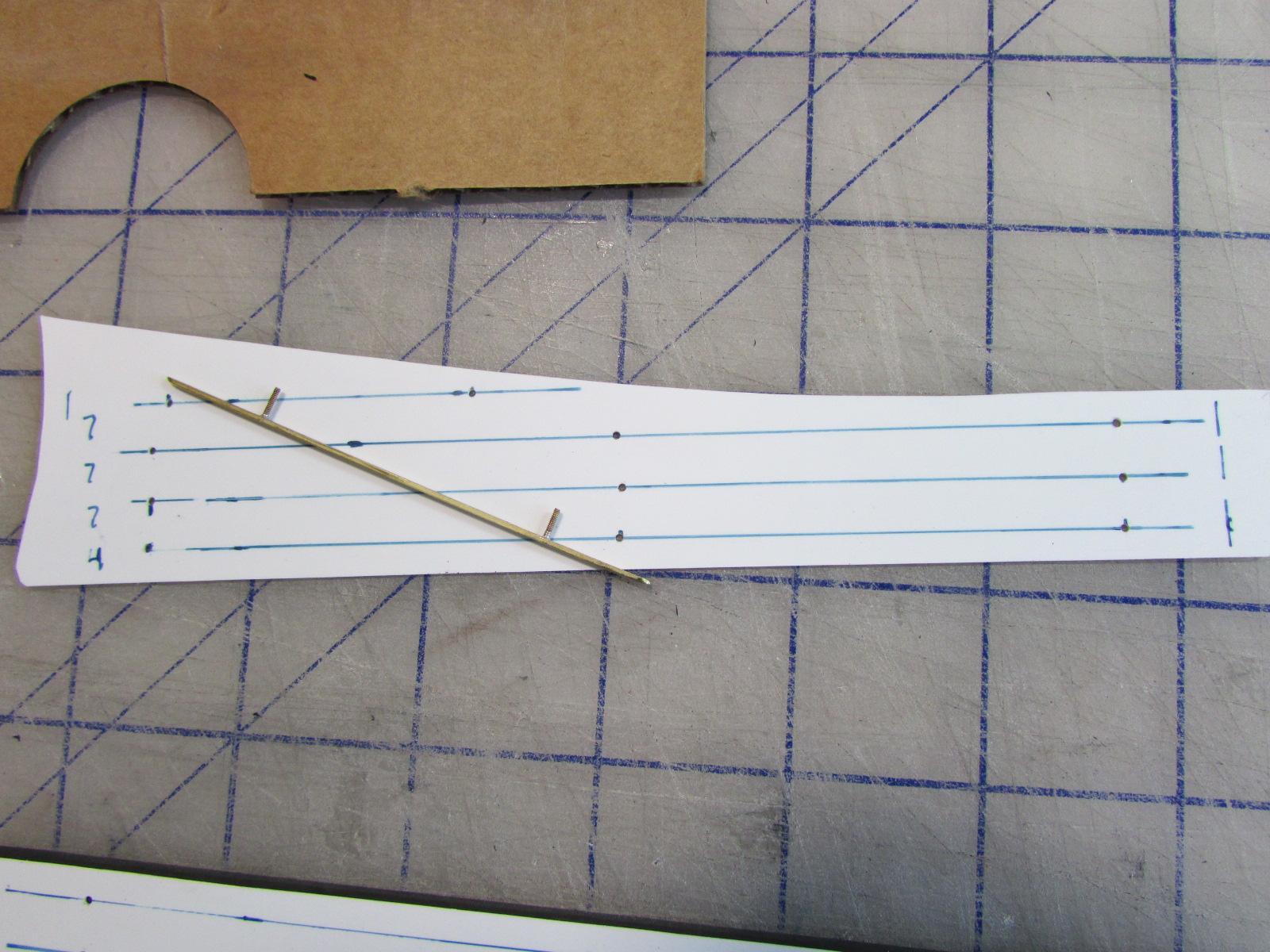
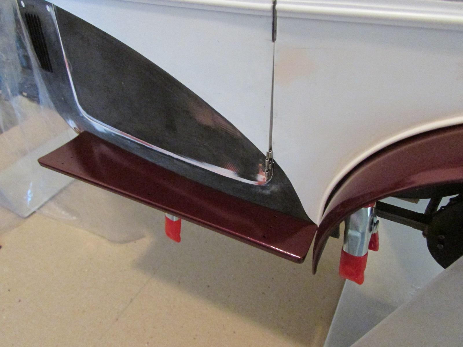
To further confuse you... A situation has occurred which caused me to divert from the above hinge / hood project briefly. To a really exciting addition of the model. Always planning ahead all the phases of construction, for some time, I had planned to make chromed brass strips for the running boards. Foil or paint on the molded strips just was not acceptable to me. But the learning curve to make them is a steep one at my skill level. So on a hunch, I contacted David Cox for advice about his advanced building techniques. Virtually all of his models feature chromed brass frames and strips in their decor. After some conversation, David offered to custom make strips to my design. I went ahead and purchased them and could not be more pleased. This saved me a hard learning project and much time. So I stopped the hood work to install them. I did this as a priority so I could return them to David for chroming as he had many bits of his own to be plated so mine could go along. I included my brass windshield frame, completed months ago. When I received them, they were also jewel-like in their craftsmanship, just as Marvin's parts are. David was Marvin's partner for some 15 years and together they built over 70 Pochers. Now David just builds for his own customers and his work on extreme and 'stock' Pochers can be seen here: http://www.detailedmodelcars.com/ In preparation for the strips, I had to sand the molded strips off the boards and then decided to make a drilling template. Seen in the first shot, the template made of .020 was sized exactly to the board. The strips are attached to the boards by 'pegs' which are inserted into holes drilled in the board. The strips are drilled in 2 or 3 places, the pegs inserted then soldered on top. The solder works down the threads to the back. The excess solder is then filed away, the parts polished and are then complete. Those pegs are actually 1mm bolts (he sometimes uses wire) which he gets precisely in even-spaced locations using dividers. This is closely related to watch-making, not model building. After preparing the boards and templates, I transferred the peg locations to the styrene and drilled .041 holes. I then placed the templates on the boards and drilled in those locations. The result is stunning and as real as you can get for a Pocher. I am much in debt to David and suggest you contact him through his site if you desire similar custom built parts - or even a whole model.
-
Great work Bo. Continue with the patient test fitting - it is vital with these Pochers. If it's anything like mine, the four hood panels and the hinge will be very difficult. Especially if the hinge parts are warped or bent.
-
Thanks Eric but I have my hands full with this obsession. I love Duesies but maybe in the next life. Work has been on-going just no 'pretty picture, show / tell stuff'. I've resisted the temptation to shoot primer and get that pretty look because of all the handling done and yet to be done. Having finalized the body, trunk and door positions, I have turned attention to the hood tops and getting a perfect fit between grille and cowl. I have gotten that straight, level hood I wanted. Took warps out of the front edge of left panel. The key was bolting the hinge halves to the panels instead of melting the pegs in place. This allows perfecting each half panel for fit. And later, painting without masking the chromed brass hinge. So far so good only to find a huge problem with the Pocher hinge; it warps upward at each end. The wire they used looks like a banana removed from the hoops. I have come up with a solution but it's tricky to execute. Will show and tell all soon.
-
VERY shoddy work Dirty Harry. No mitered corners anywhere......
-
Everything Bill said plus; Use the tiniest bit of hardener in your mix. You just want it to turn very slightly pink - or you will have no working time. It will kick too fast. If it does, mix another batch; don't try to use it.
-
Harry, this reminded me of your 1/16 wooden bipe; the Sopwith Camel(?) Shame it's not 1/8 scale to go with this but you could shoot it next to your 'test' 'Brake (1/16); I think both wood models would look smashing together.
-
Amazing what Revell is pushing out the door these days...and sad.
-

How to Remove "Ghost Trim"
Cato replied to diymirage's topic in Model Building Questions and Answers
Yep. That will last you 100 years. -
For your next build; A 427 has a front mounted distributor.
-
How to Remove "Ghost Trim"
Cato replied to diymirage's topic in Model Building Questions and Answers
Cement will only texture the surface which you don't want. When you sand that, you're making your piece even thinner. Just shoot Future on the bare plastic. Only one step and you have nothing to lose. Then prime. -
Thanks for digging this thread out Mike. I see I need that bottle which draws the fluid in.
-
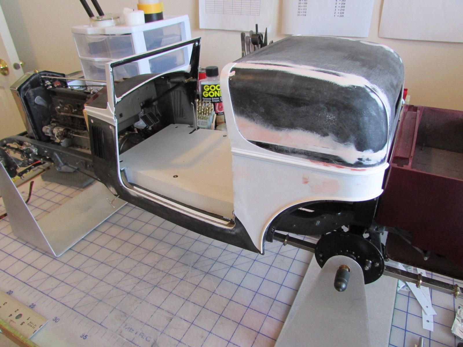
Here's an early test fit; firewall even with grille shell (too high) and body cowl even higher. Compared to the above it makes me very happy I did all that surgery to get to this point.
-
No judges in the future; I'll be happy just to see it every day if it comes out as I hope. Thanks for the very kind words Tim.
-
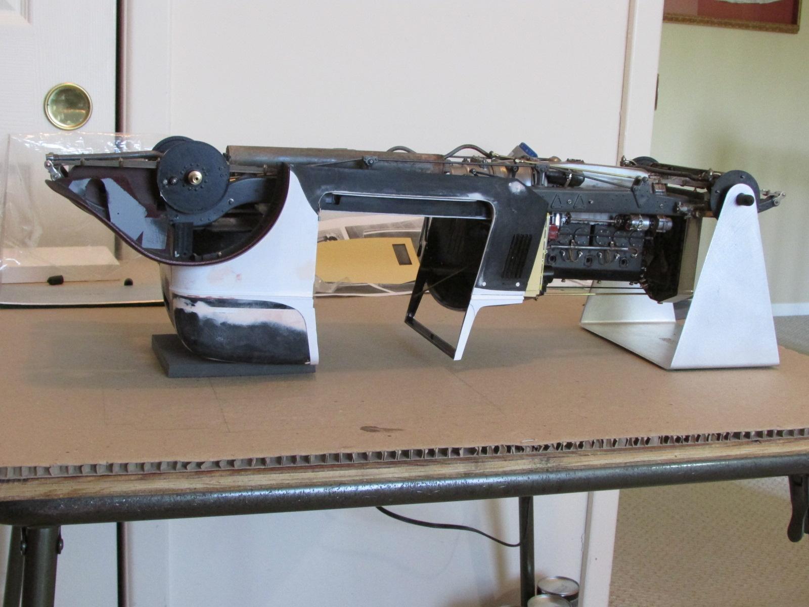
Important but not exciting... I have been working every day since the last update so here is the important result. The body and floor mate as a unit and the whole assembly mates to the chassis - in a solid and repeatable way. You've seen many prior pictures of the car mocked-up this way but there is a difference now. Many hours of measuring and test fitting improved it all. I went back and made stronger, more accurate locations for all mounting points. I added two new ones (total of 6), and a pair of chassis brackets which now secure the lower front of the body. I made improved 'clamps' to securely hold the floor unit to the body lower flanges. The trunk aligns with the body perfectly. No Pocher screws anywhere; all fasteners are by 6, 2mm studs, tapped and epoxied in place with nuts. The lower front of the body uses 0-80 bolts with nuts through a brass bracket. I will post all the 'fill-in' shots of these parts and assemblies soon. But here is the result. For the first time, the unit sits flush on the chassis and firewall with no bind, twist or warp; it just glides right onto the locating studs and the bolt holes align. A 'tee' pin is seen in the lower front where the bolt goes through the bracket. They fit perfectly with all the other locators in place, a very rewarding feeling. This is what lets you install and remove body work for finish and interior and have it all go back precisely and unseen when carpet and seats are installed.
-
How to Remove "Ghost Trim"
Cato replied to diymirage's topic in Model Building Questions and Answers
Airbrush Future on completed body work then primer. Future is an excellent barrier. -
Another tip... This is primarily for Rolls builders but may work on other hard-roof cars like Alfa Coupe and Bugatti. I needed to work the bottom of the chassis but with the body attached. I've made body mount brackets (will show soon) which bolt to the bottom rails and connect to the new, lower body edge. First attach the body / floor unit to the chassis. I have 2mm studs through the rear floor and 0-80 bolts through the front floor. If you have workstands, remove the rear one and carefully invert the whole car. Rest the roof on a pad and you're done. Solid and safe to measure and attach parts. No front fender though because of the front stand. I knew there was a good reason I whacked the windshield down. Almost as good as a rotisserie...
-
Maybe a little Dullcote to knock the tire treads down? Instead of all that sanding dust....
-
Very nice work Bo. What was the solution to the white paint on the firewall?
-
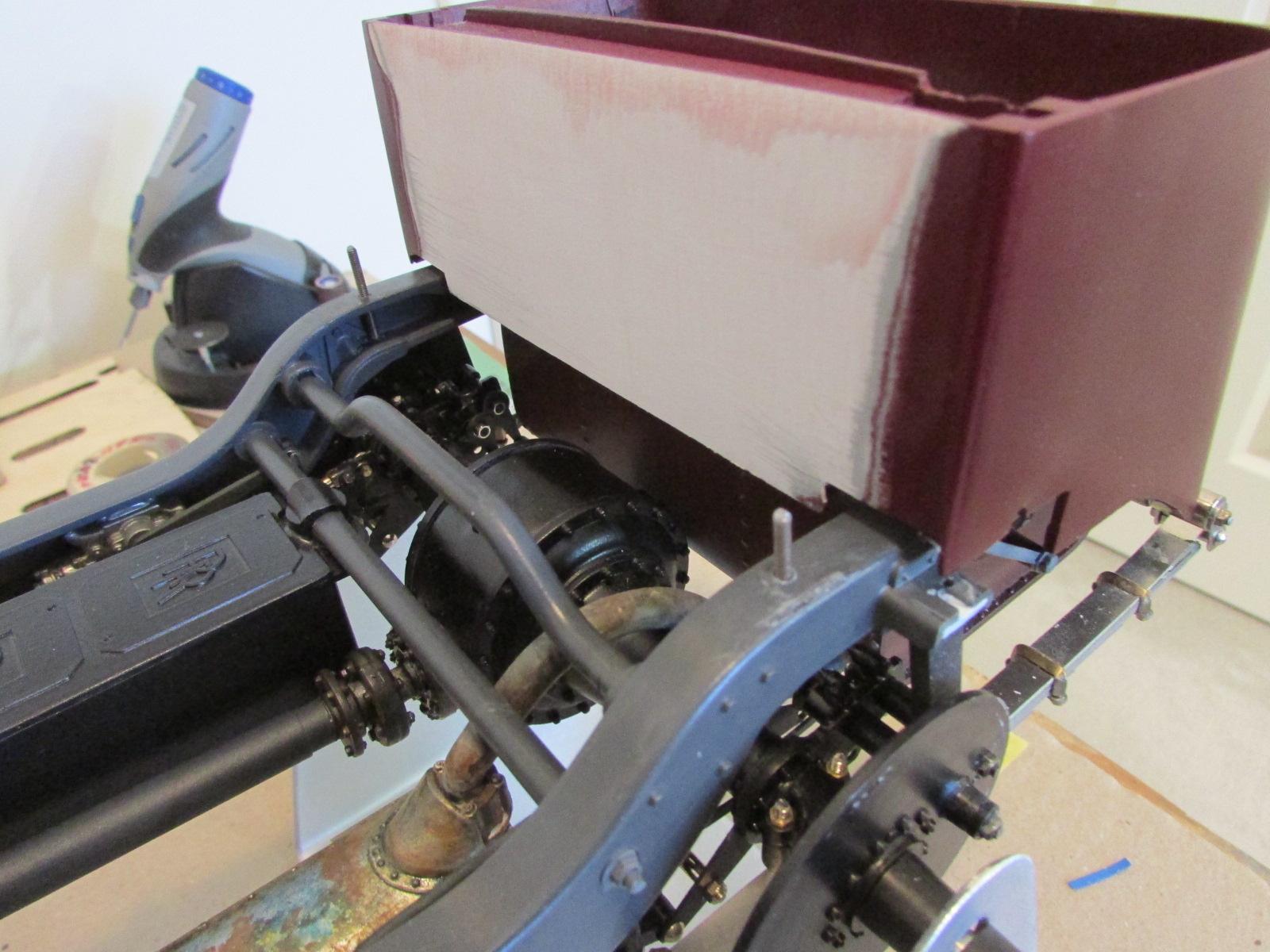
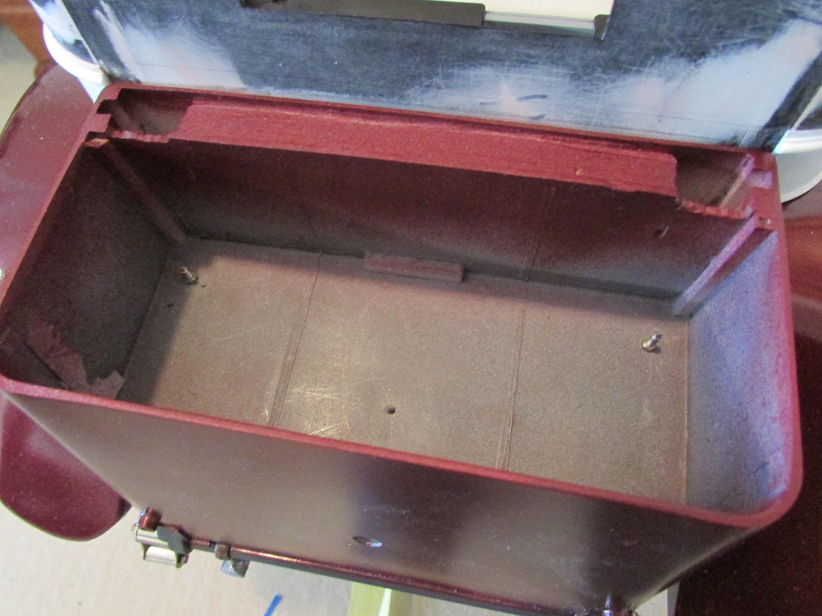
Lucky sometimes... As described, a bunch of planning and test fits have been going on before the next big project; soldering up window frames and door assembling. In particular, I needed to get the trunk and rear fenders fastened solidly to the main structure. I kind of hit a wall with this boring stuff so I began disassembling the last mock-up to begin the door work. And then, an idea simply presented itself. Having made several types of brackets and looked at 3 types of screws / bolts, I had no satisfactory way to secure the trunk. But the simple answer was, the same way I secured the rear of the floorboard. Using 2mm threaded rod, I had drilled and tapped the chassis and made a 'stud', then drilled the floor in the exact location (fun) and retained with a nut. I've had the floor / body unit on and off literally countless times and the system has been bulletproof. So using some soft putty placed on the chassis in the approximate area, I placed the trunk in position and compressed the putty. This gave me the height of the spacer block I'd need. After measuring, 1/8 x 1/4 styrene rod was cut to 15mm long and checked for fit between chassis and trunk bottom. Much careful measuring of the distances from the rear of the body and in from the trunk side followed. This determined where the block should sit on the chassis and where holes should be drilled in it and the trunk floor. All this was necessary because the trunk has been severely altered from stock. Seen in other pictures, the details atop the gas tank had to be removed in order for the trunk to sit square in the chassis. No matter, as they are unseen even in a stock build. The chassis paint was scuffed in the area, the block also. A bit of German gray will make this all disappear later. A .062 hole was drilled off center in the block and matching place on the chassis. A peg of styrene rod was inserted to make a small locating peg which (along with the 2mm stud) would prevent the block from ever moving. A drop of gel CA and then the #49 hole was drilled and tapped for the 2mm threads. Then CA on the threads as they sank down to the bottom of the chassis channel. Trunk holes were located and drilled slightly oversize. A washer will be under the nut upon final assembly. I lucked-out with a perfect, secure fit. Once again the value of stout (compared to Pocher screws) removable 2mm fasteners are highly recommended to Pocher builders. I can now make simple 2mm bolts, (a nut CA'd to a length of threaded rod) to secure each fender to the trunk body. Just a lot of tricky measuring and a tapped block inside needed. I may not have to attach the trunk to the body because 4 studs already hold the floor unit to the chassis. Actually easier to do than write about. Overcoming a stumbling block always gives you much enthusiasm to move ahead...