kenlwest
-
Posts
258 -
Joined
-
Last visited
Content Type
Profiles
Forums
Events
Gallery
Everything posted by kenlwest
-
Dave, the original drawing was 1/16, but both printed models are 1/12 scale.
-
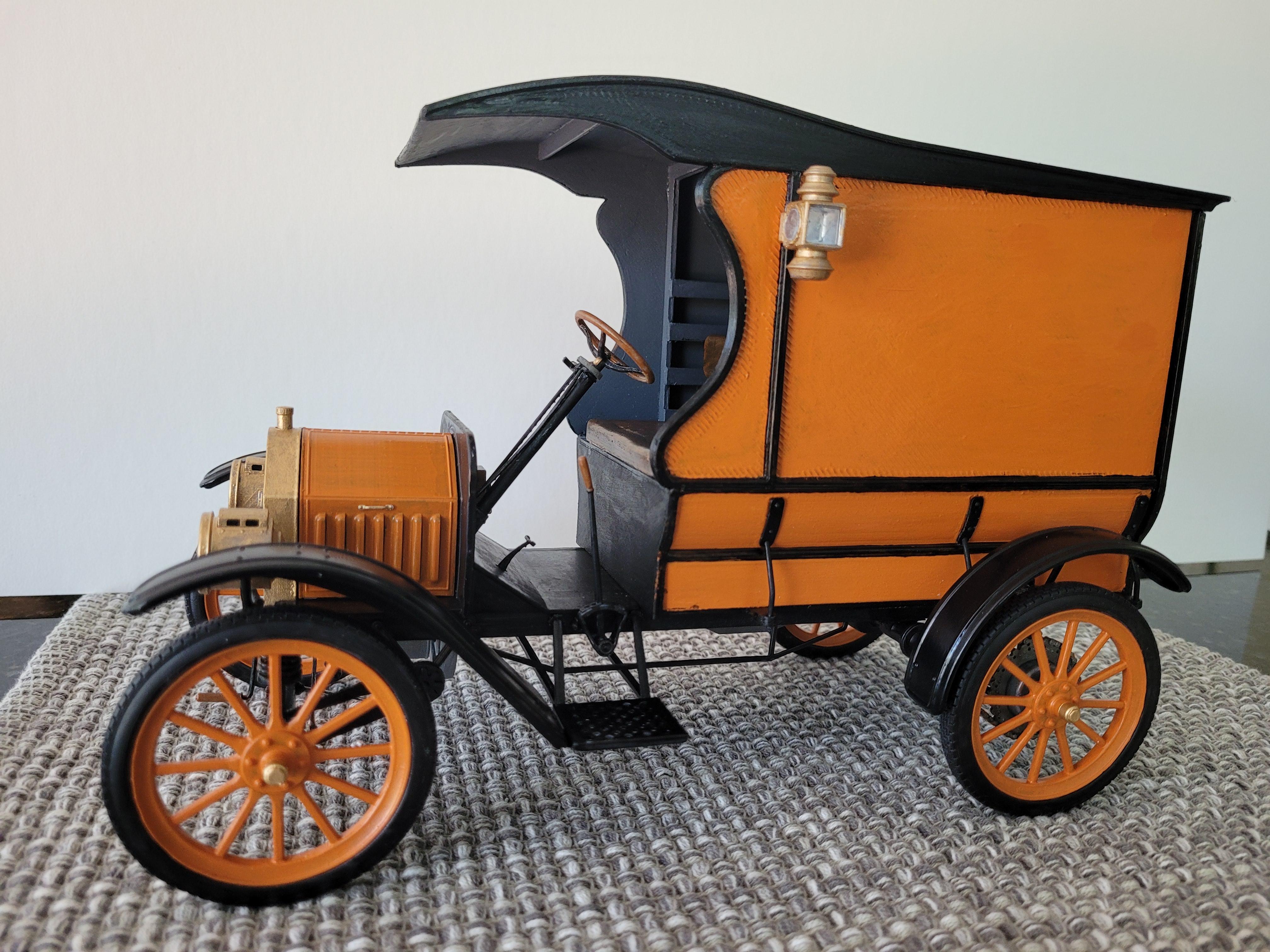
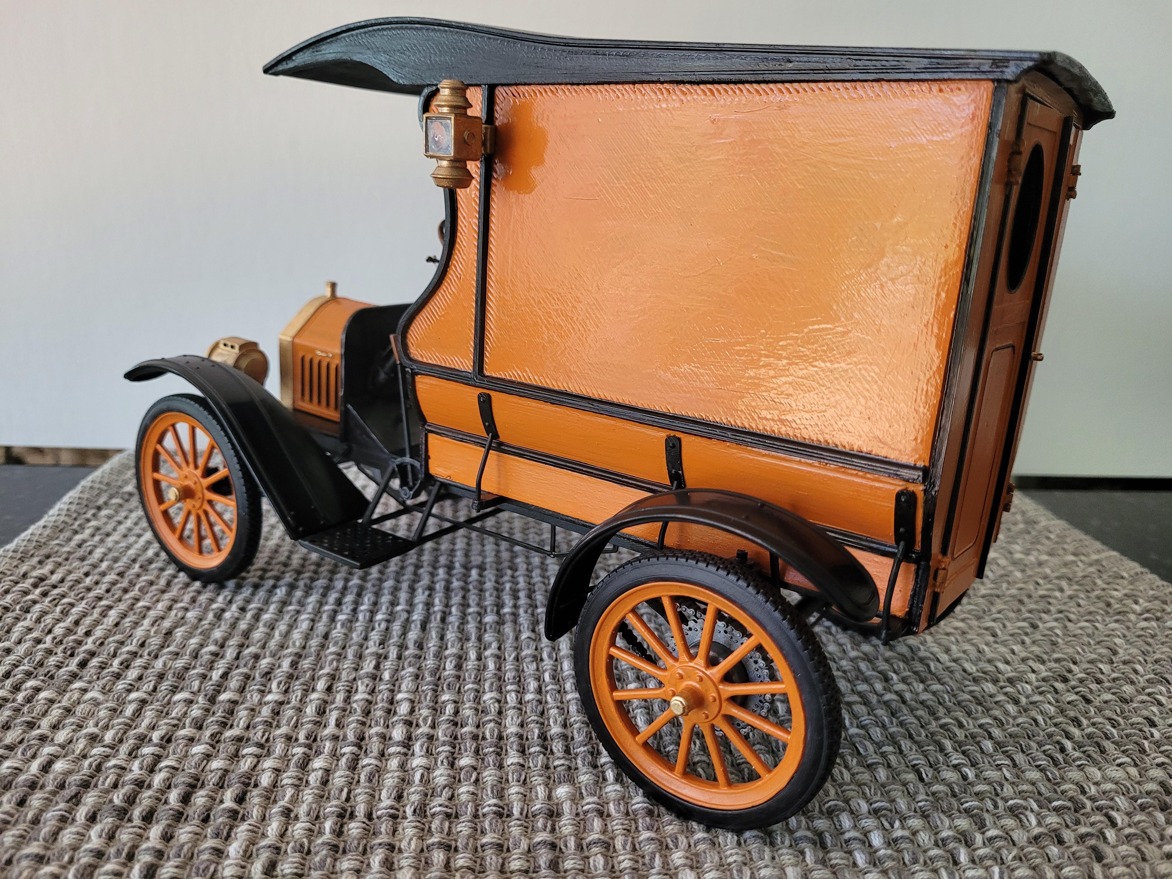
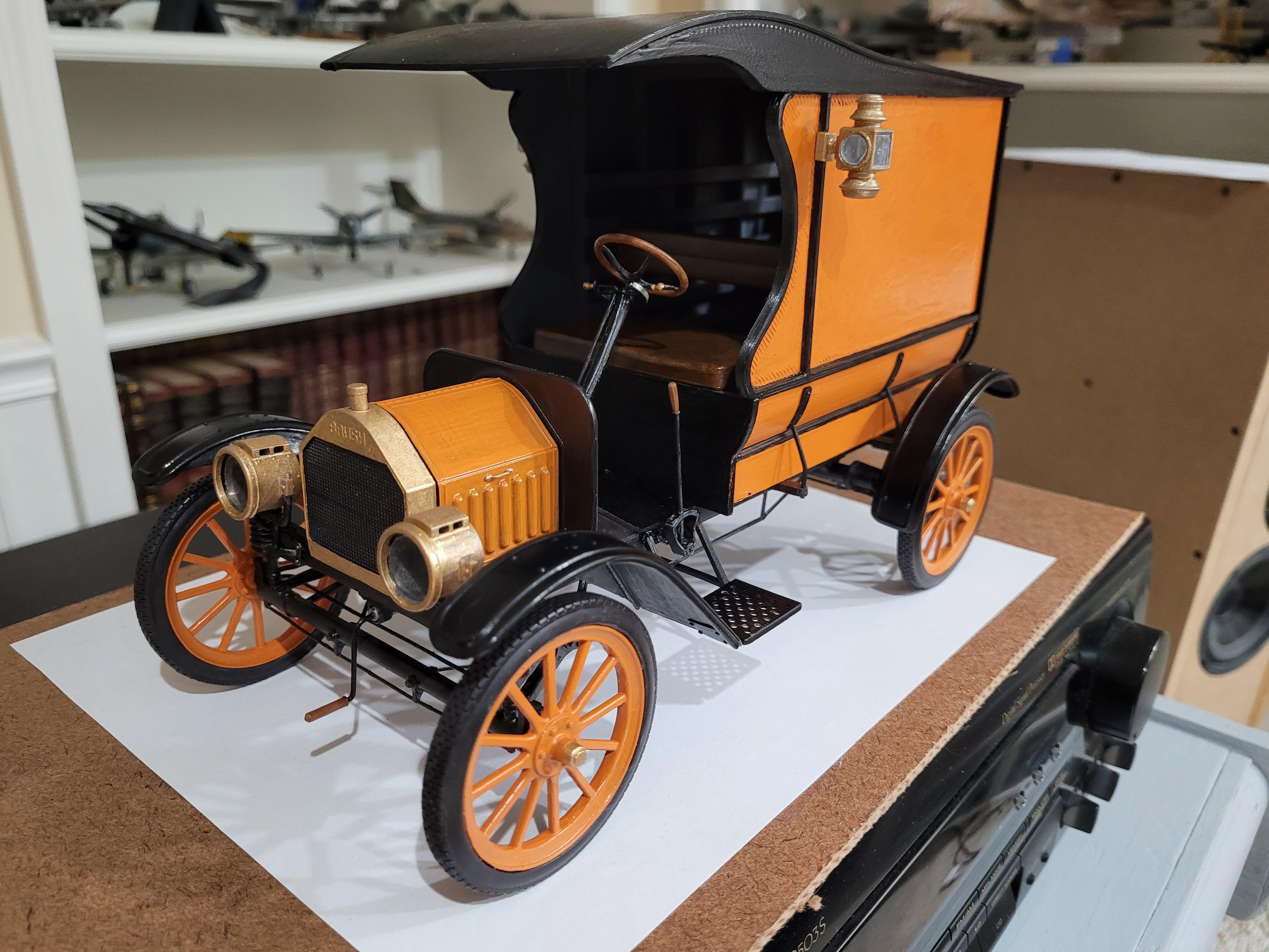
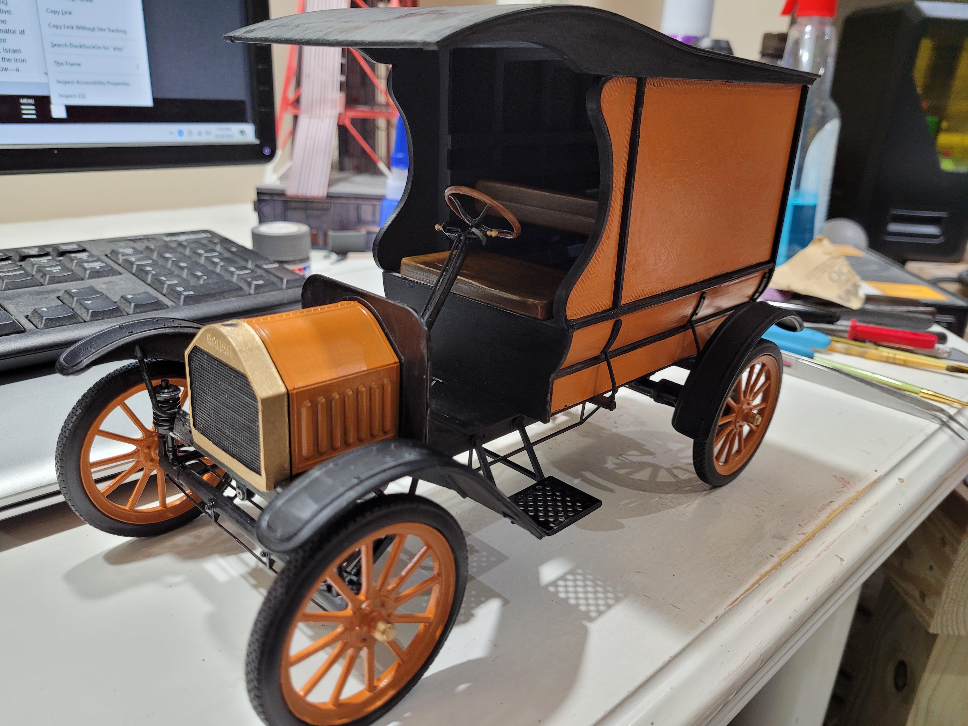
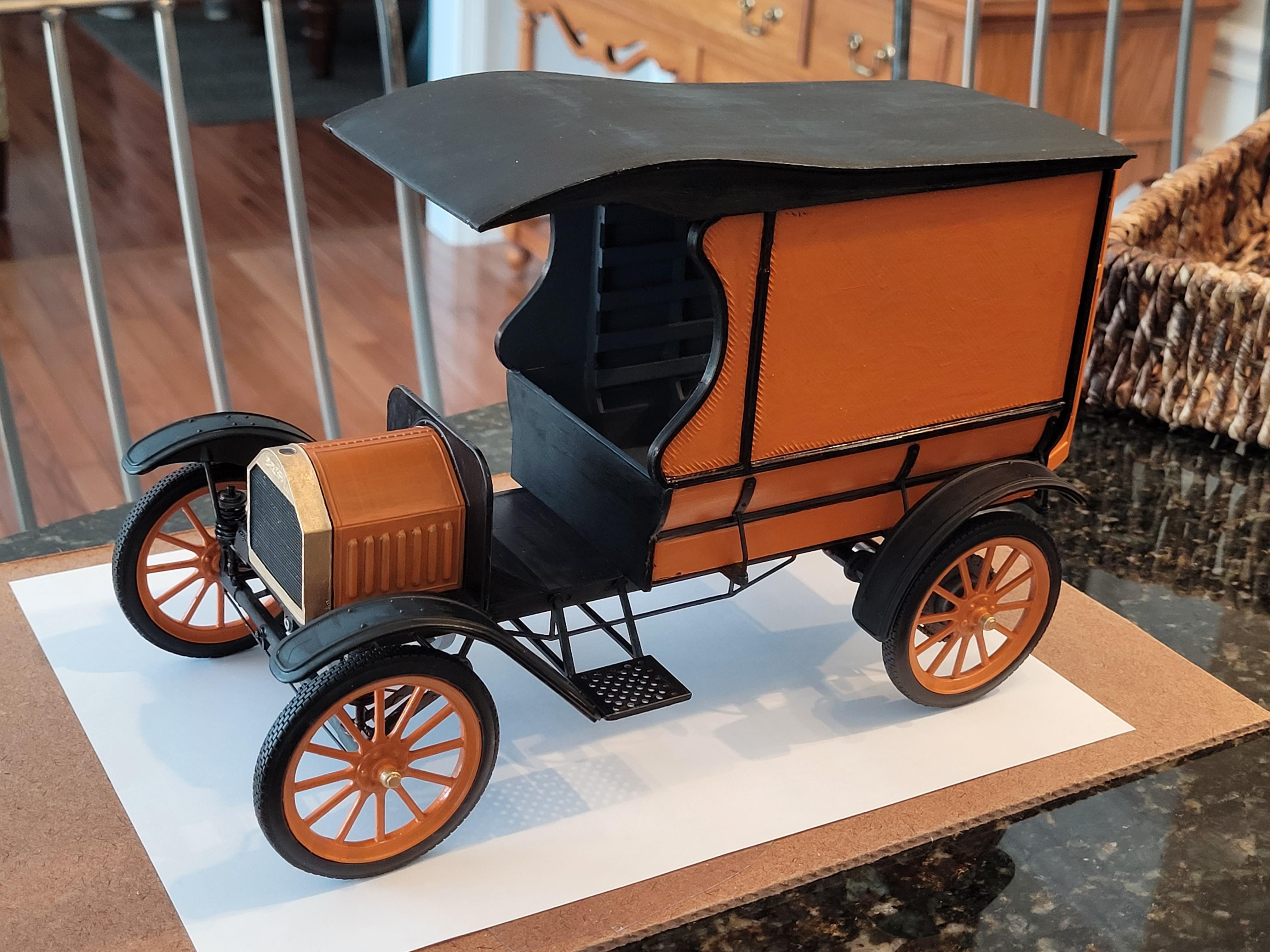
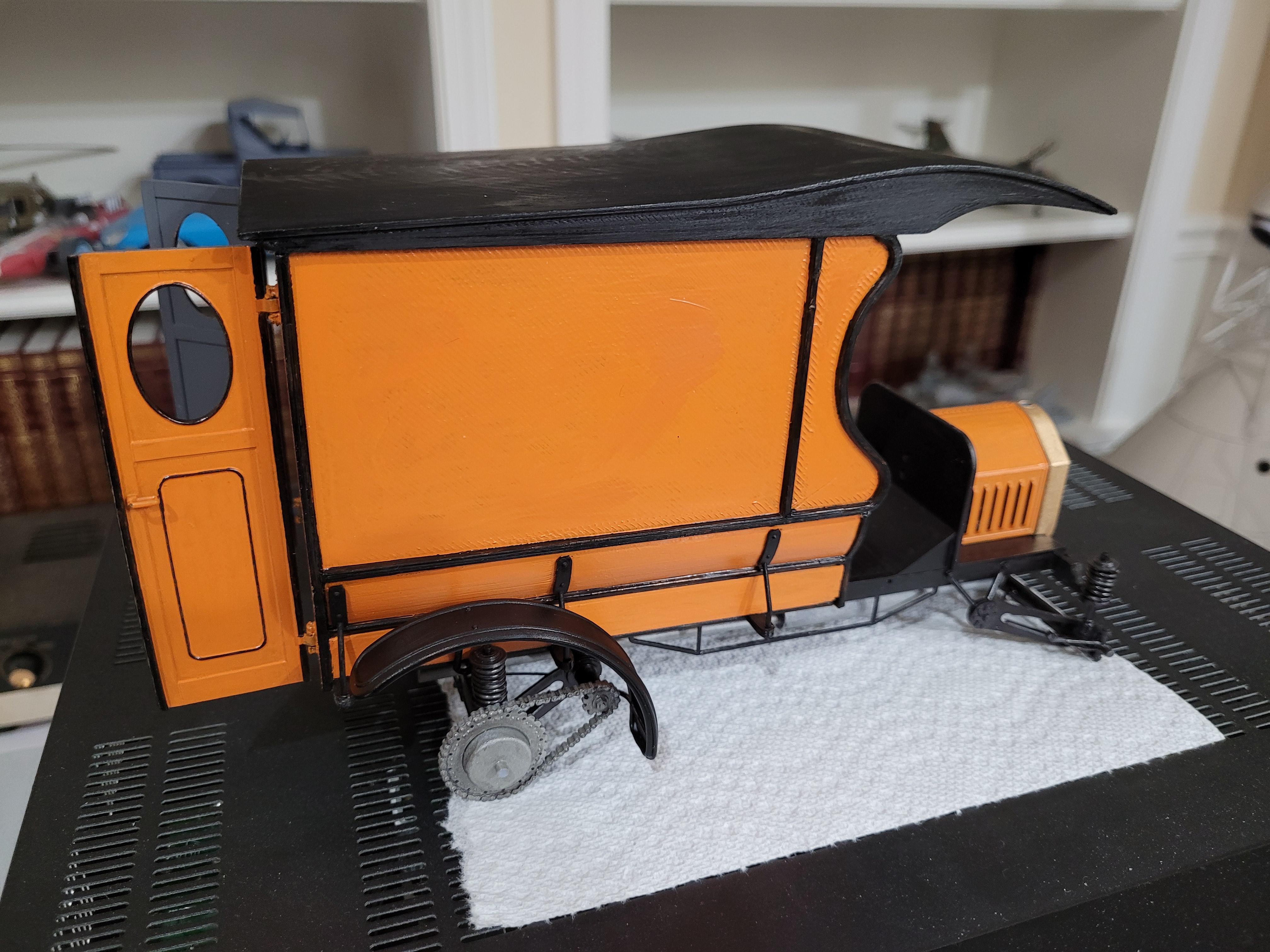
This was a redesign and rebuild of a 3d model that I transcribed into CAD from an old Hudson Miniatures model plan from 1949. For comparison, the last picture is the original built several years ago, and the rest of the pics are of the significantly improved version I just completed.

-
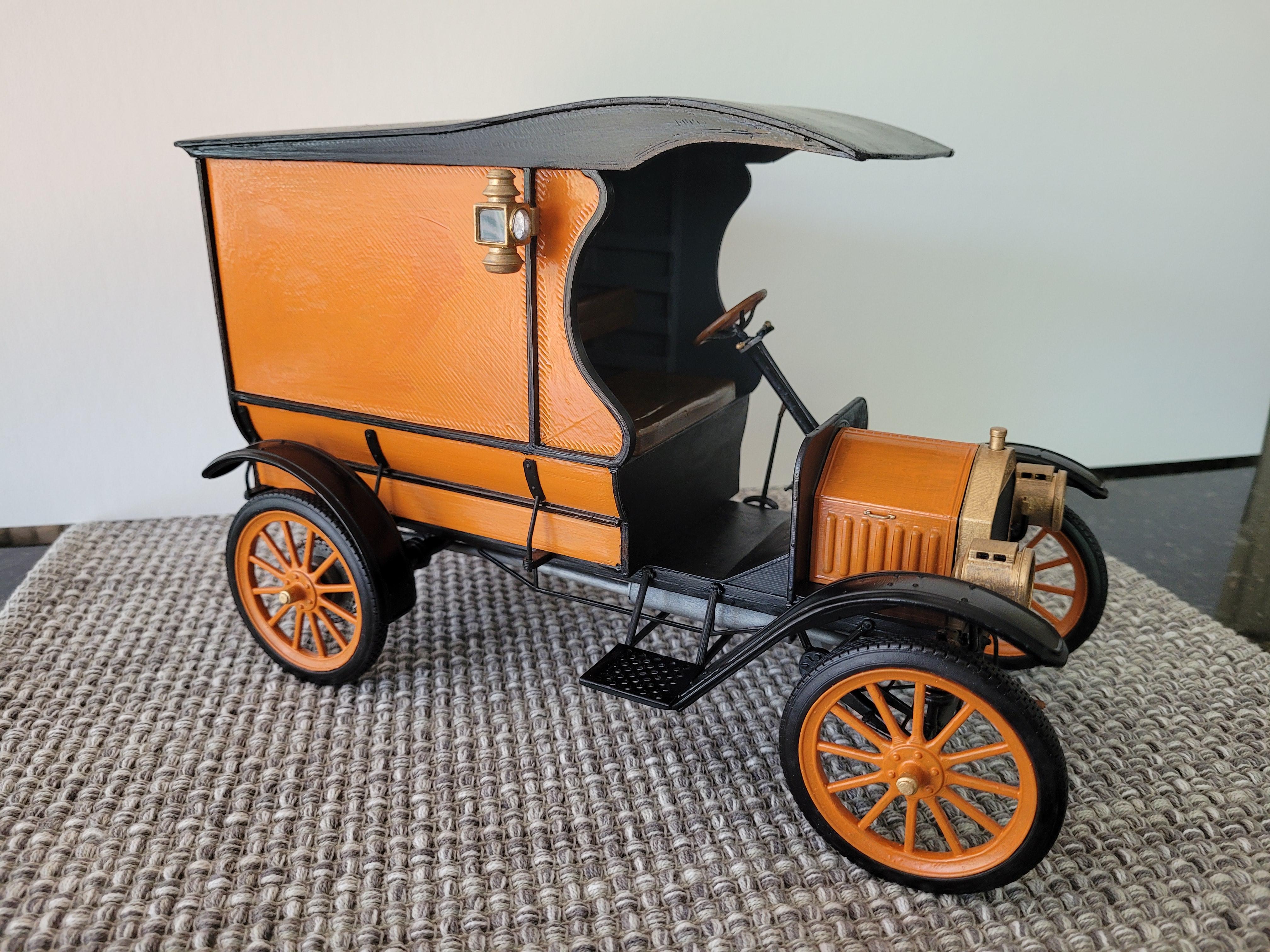
Tonight I finished the truck. I added the headlights, the coach lights, crank start handle, hood grab handles, and shift handle. I will take pictures tomorrow and post them in the Under Glass section.
-
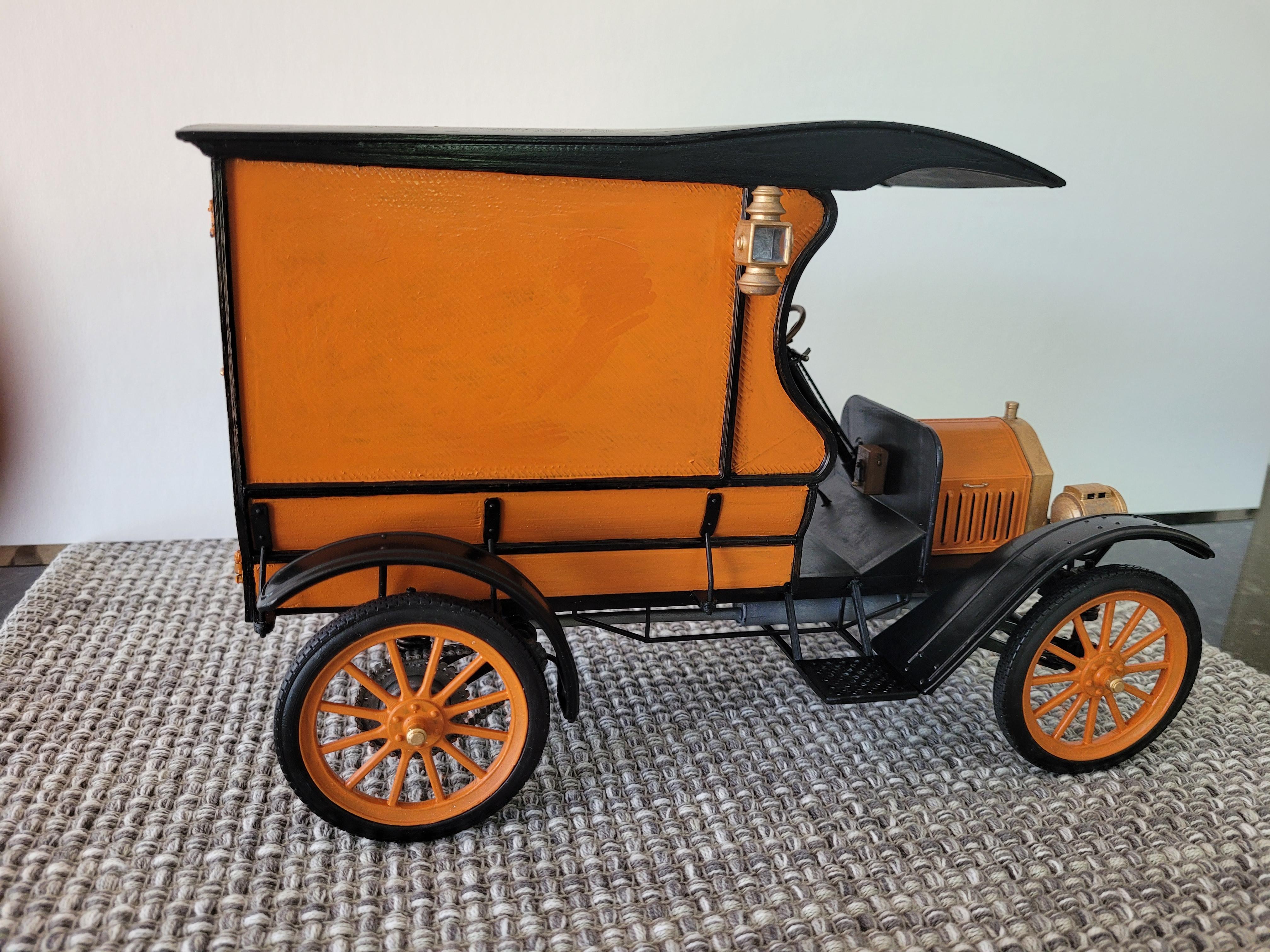
The cargo box is permanently attached to the chassis.
-
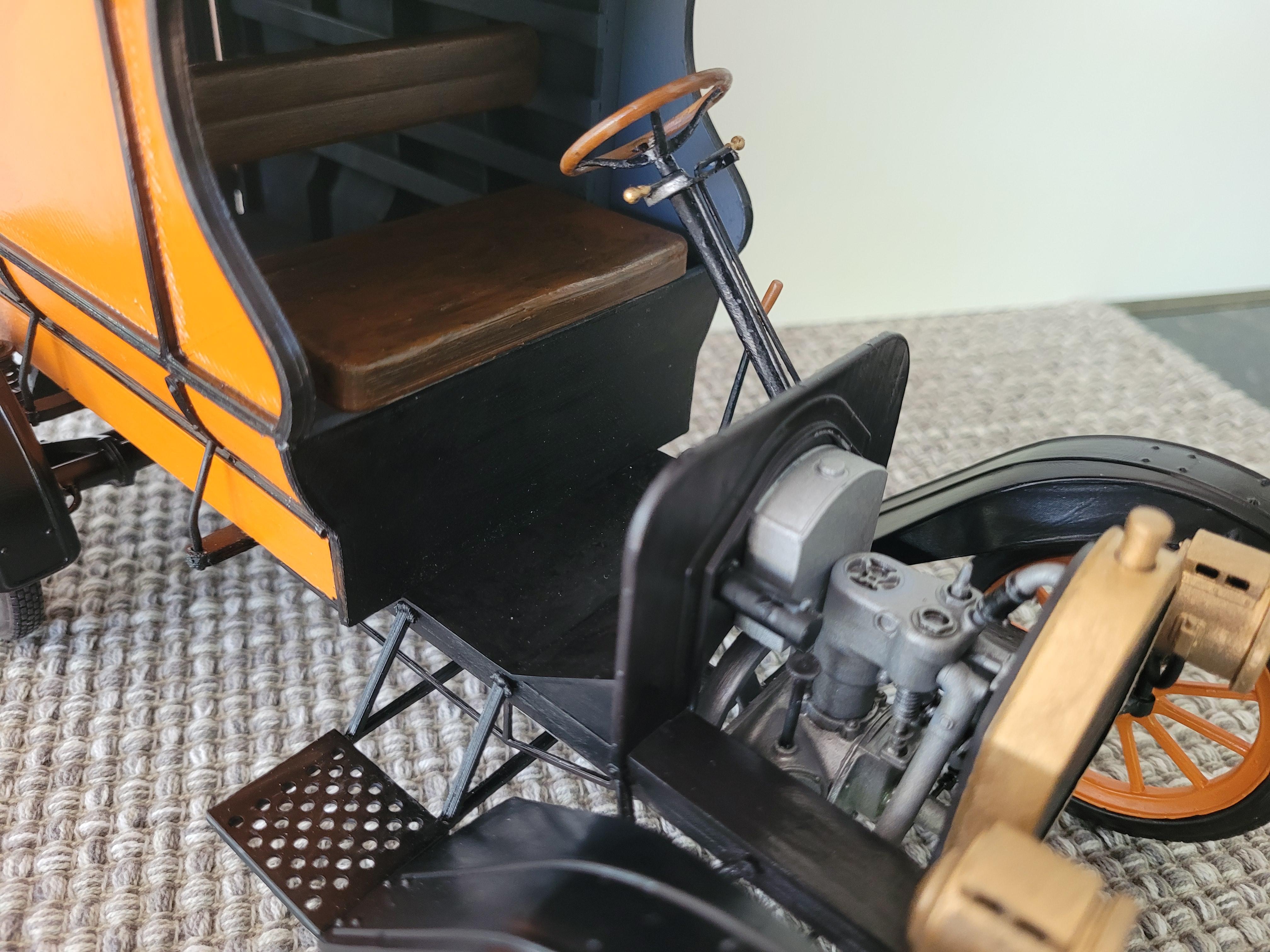
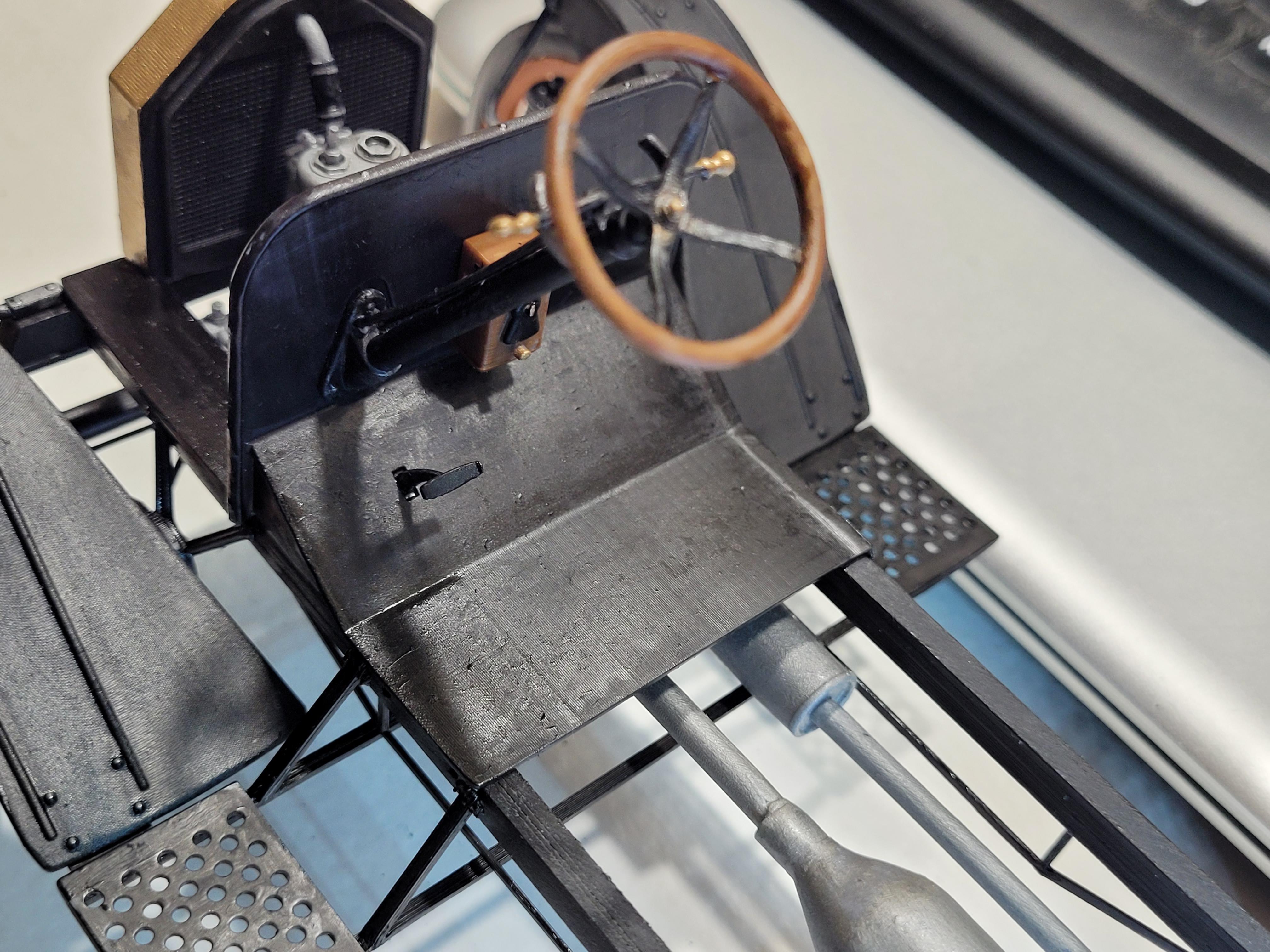
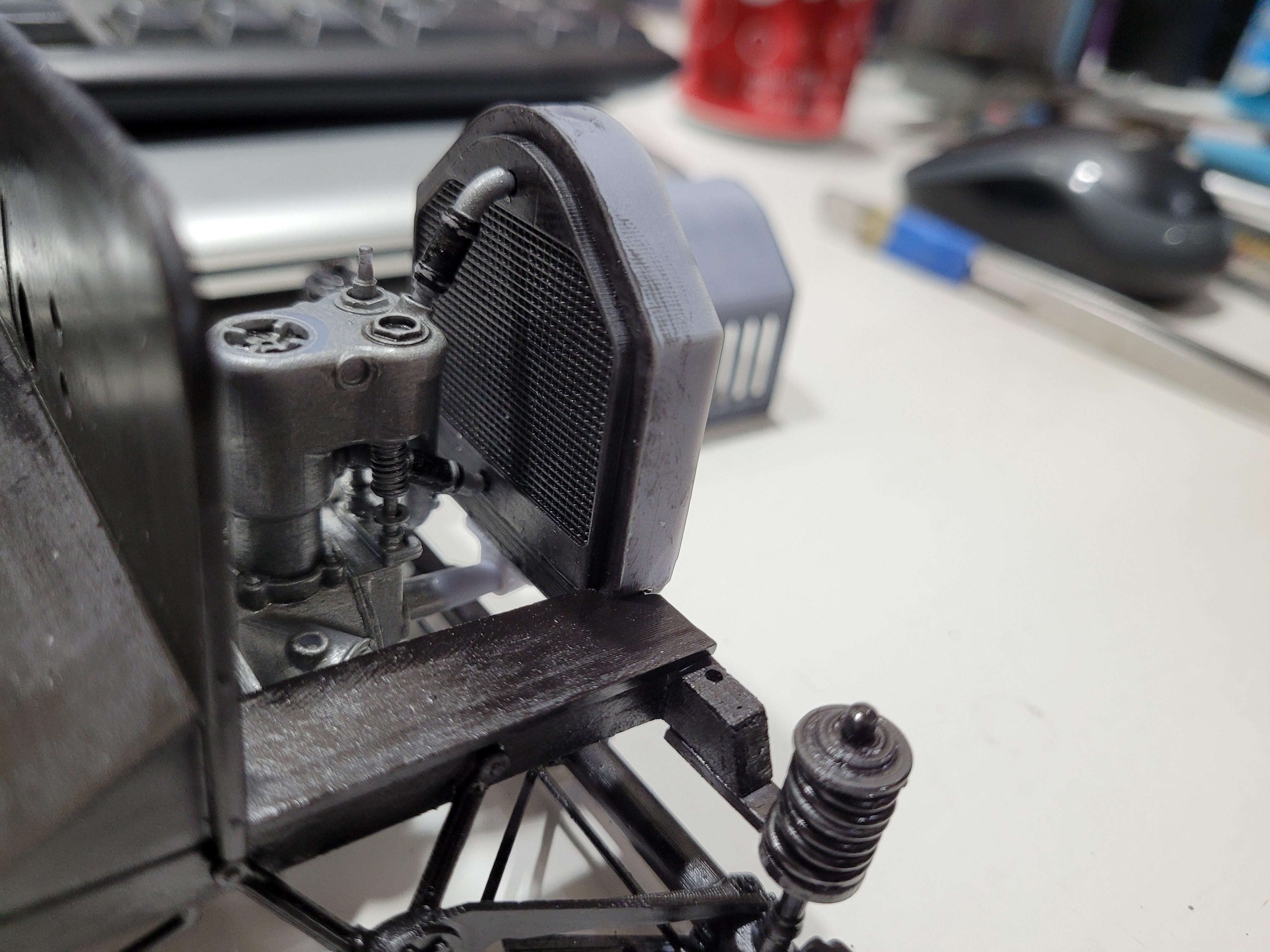
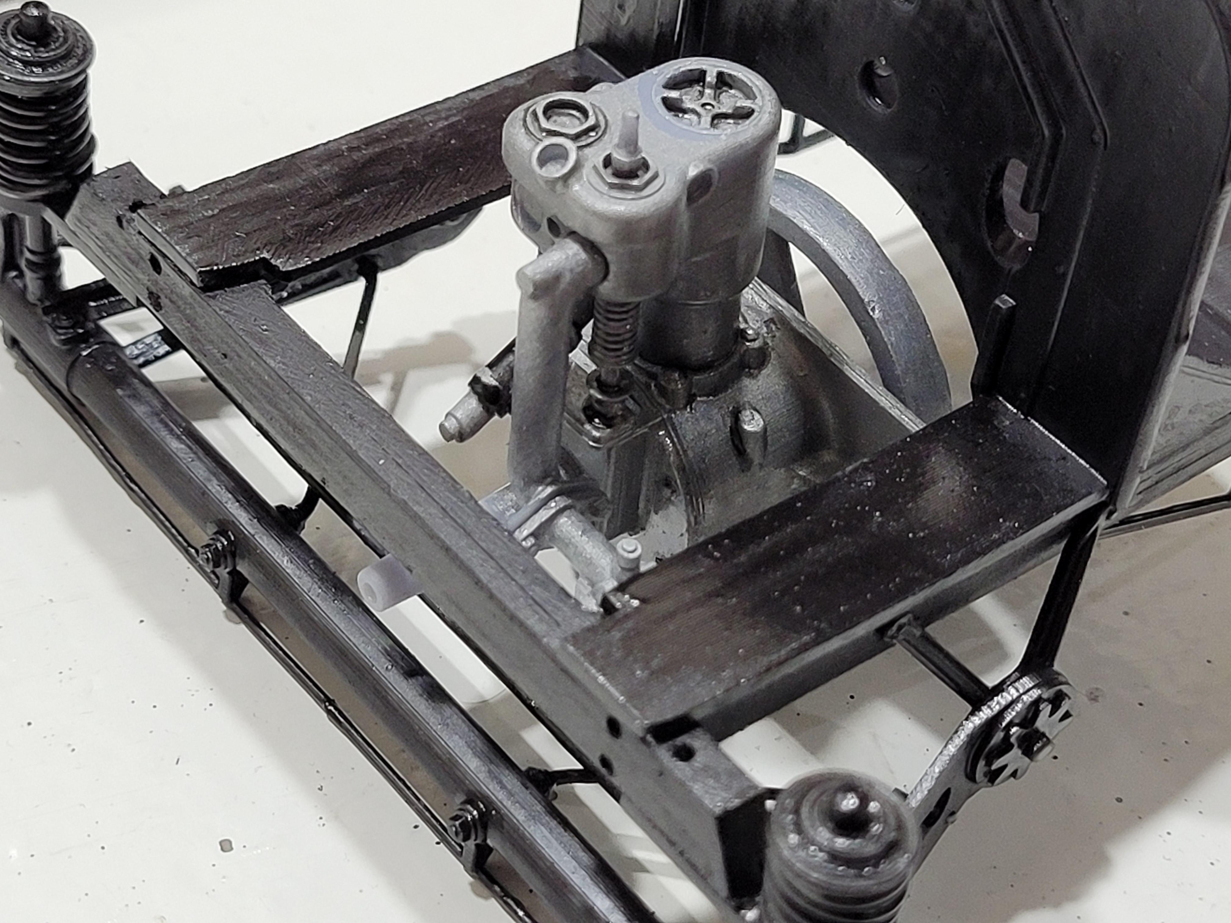
Steering column and various controls.
-
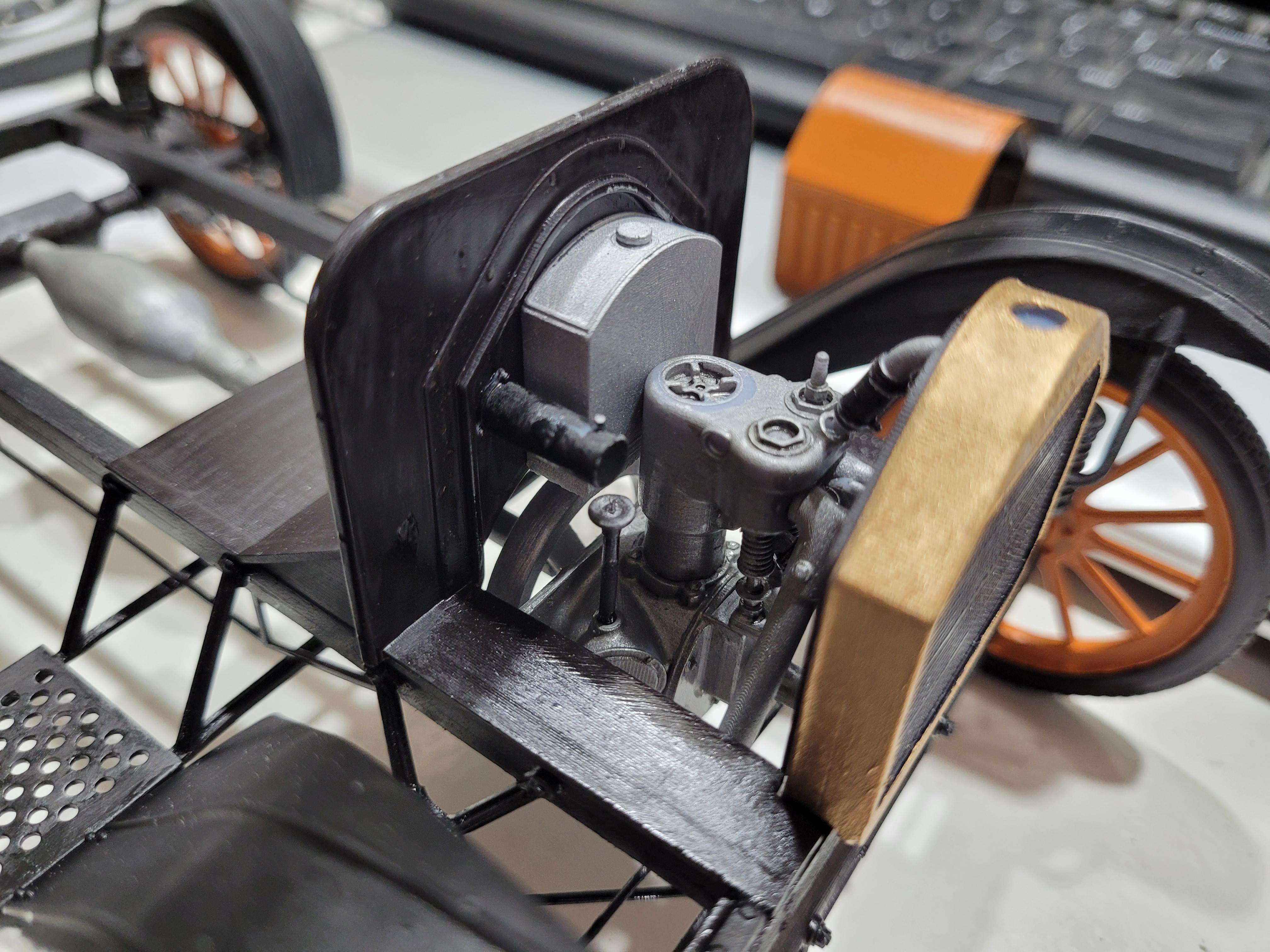
The fuel tank is mounted on the cowl panel. I am not sure what the horizontal black cylinder is for. The engine side of the steering column is in place and connected to the drag link.
-
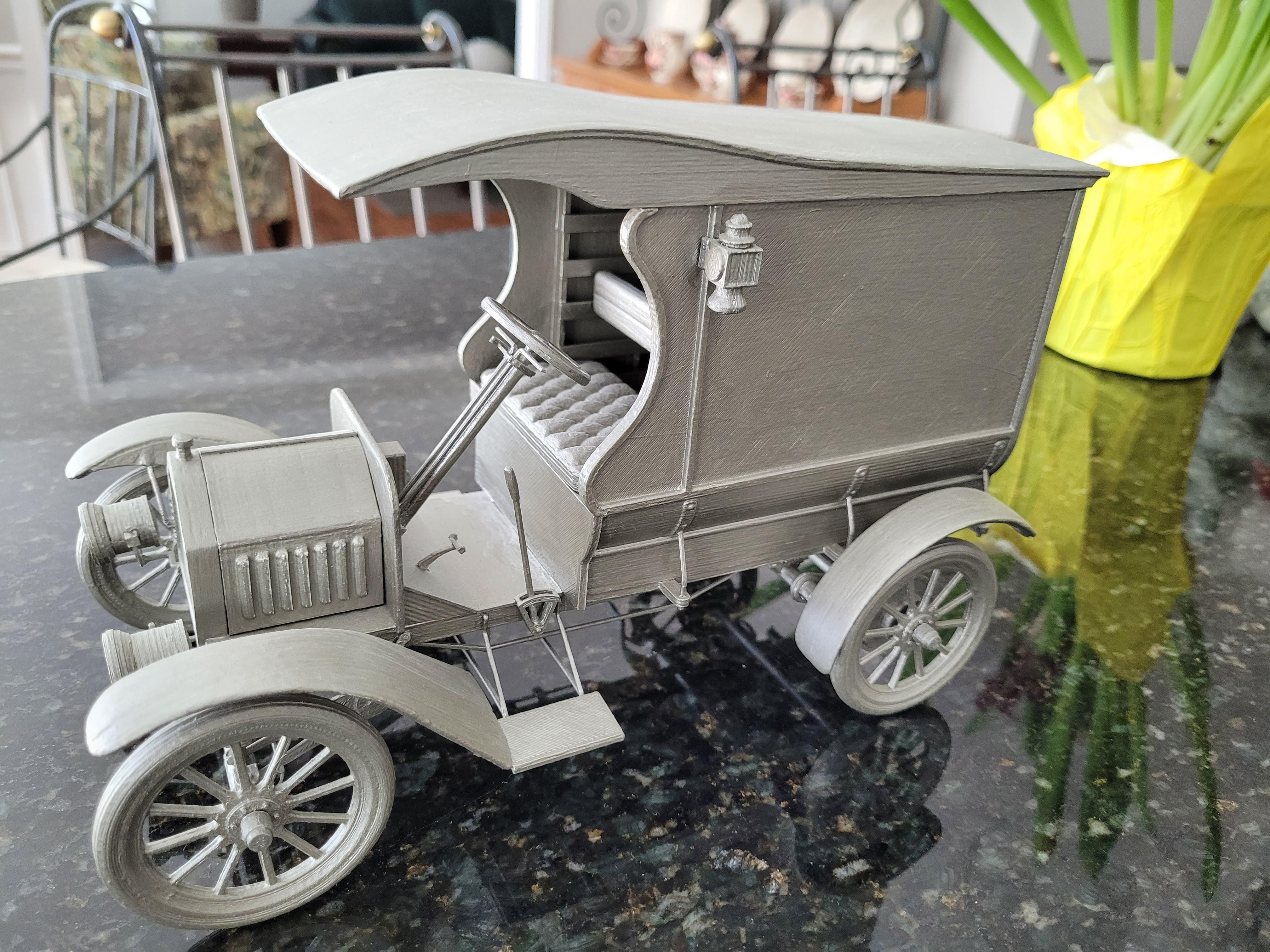
The seat cushion and seat back in place. You will notice that the paint finishes on this project look rough and dull. This is intentional. The final coat will be a water-based polyurethane. In my experience, this creates a more antique period look.
-
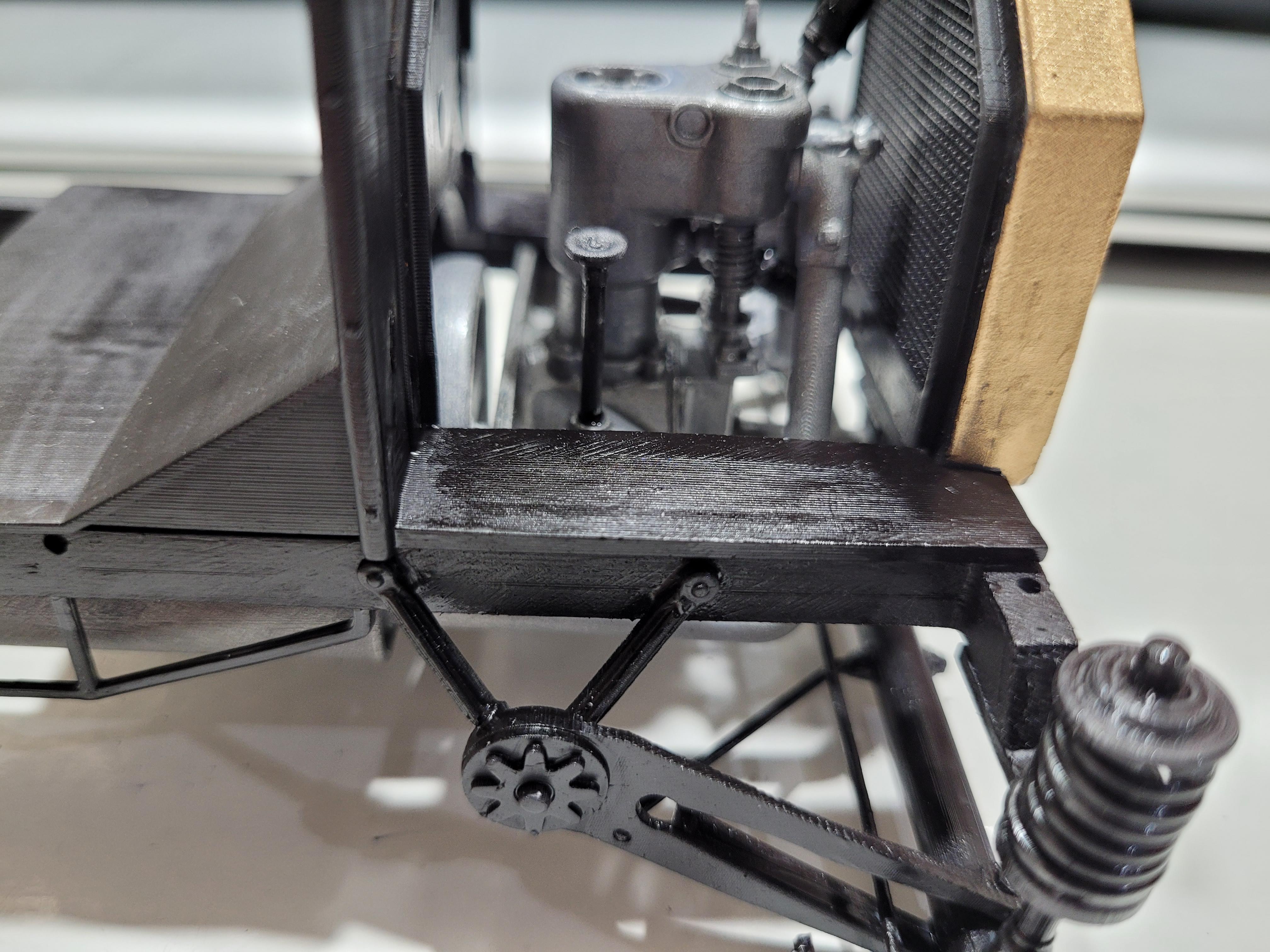
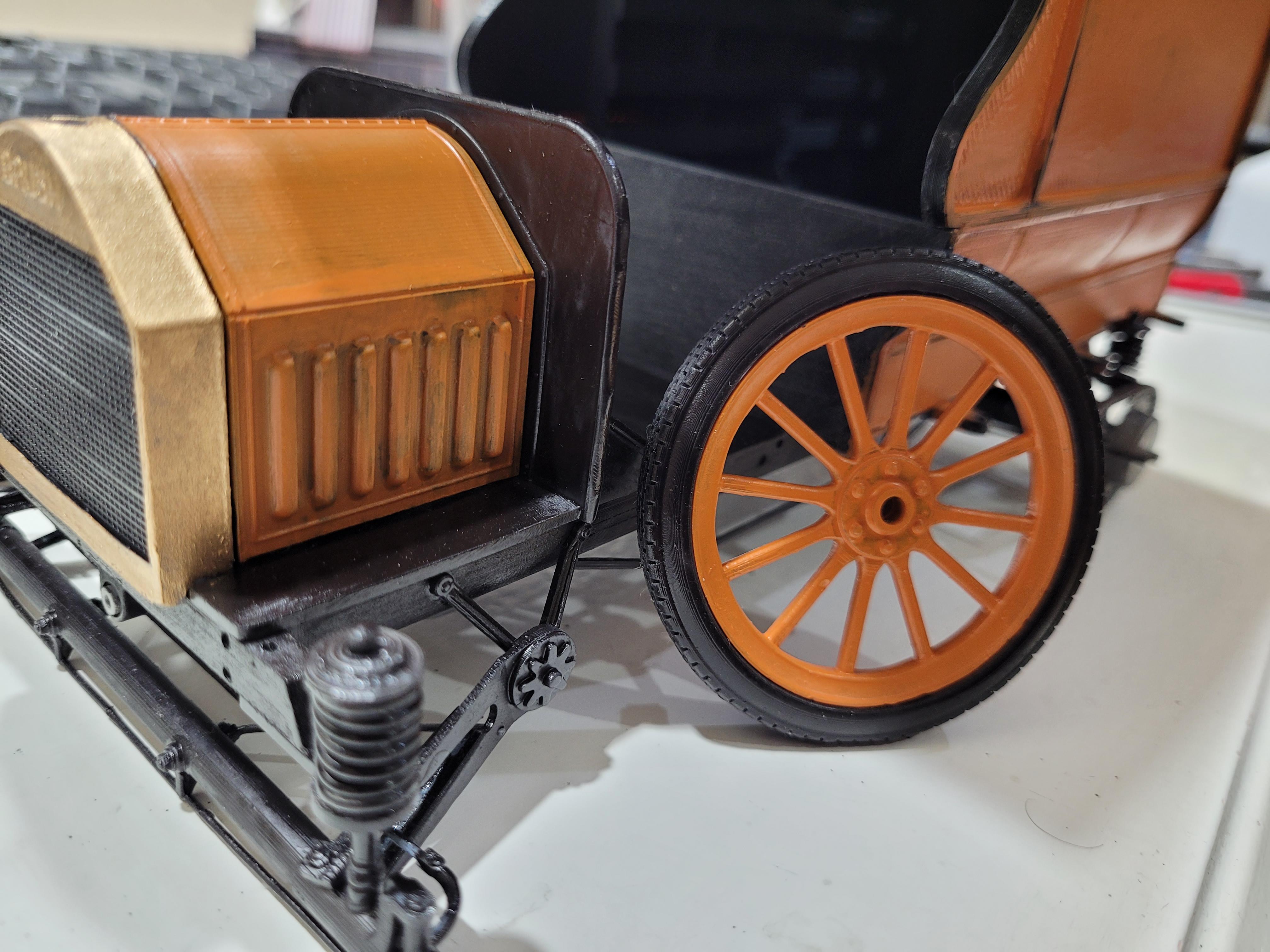
Like many other unique features of this vehicle design, the cross braces are used to support the steps, and also to support the front fenders. The wheels are mounted. A lot of details yet to be added. I am still looking for a fake business logo for the side panels.
-
There are 6 tension brackets that were used to hold the cargo box to the frame, shown here.
-
A preview..... cargo box sitting on frame.
-
The rear fender are attached.
-
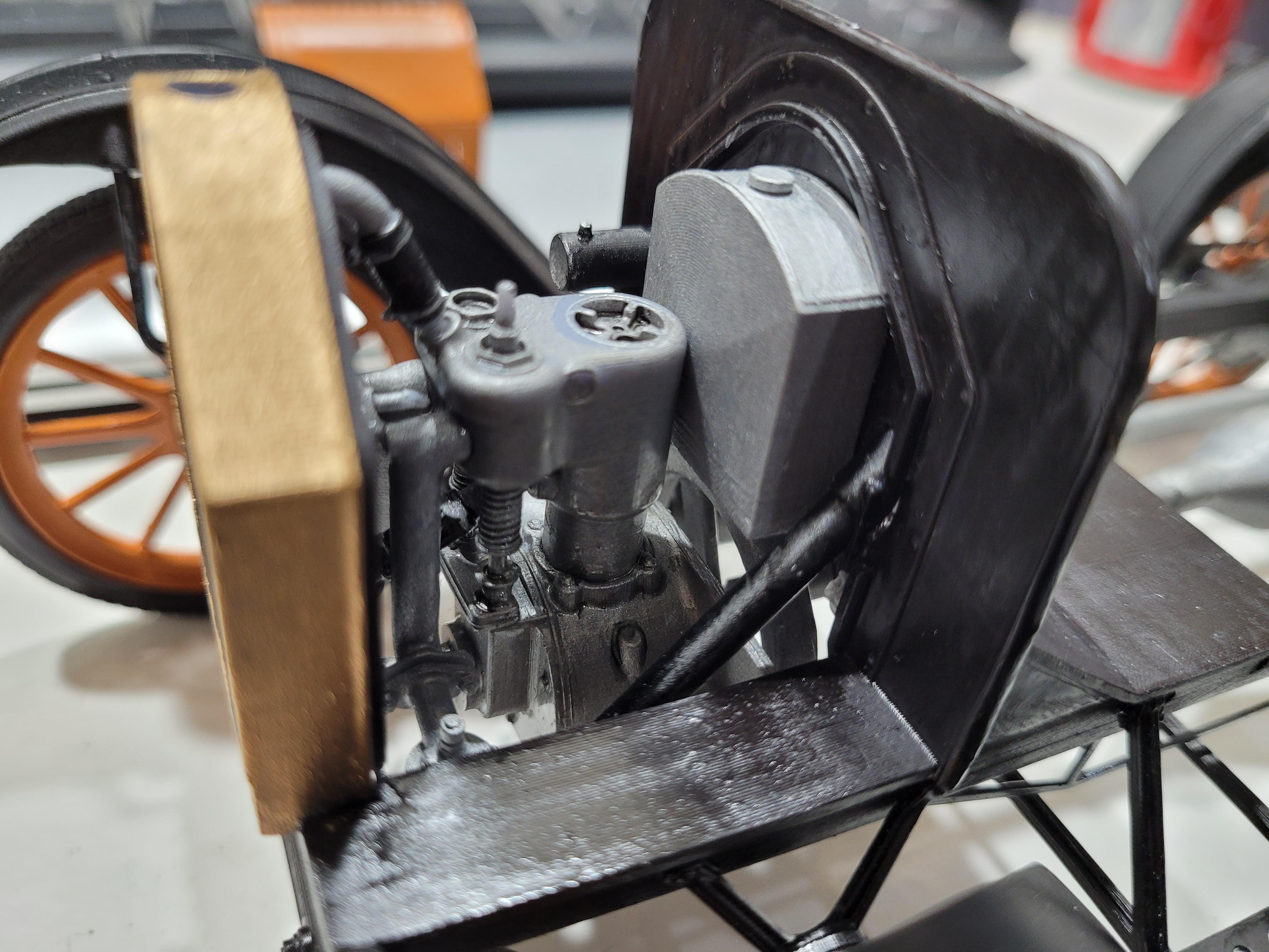
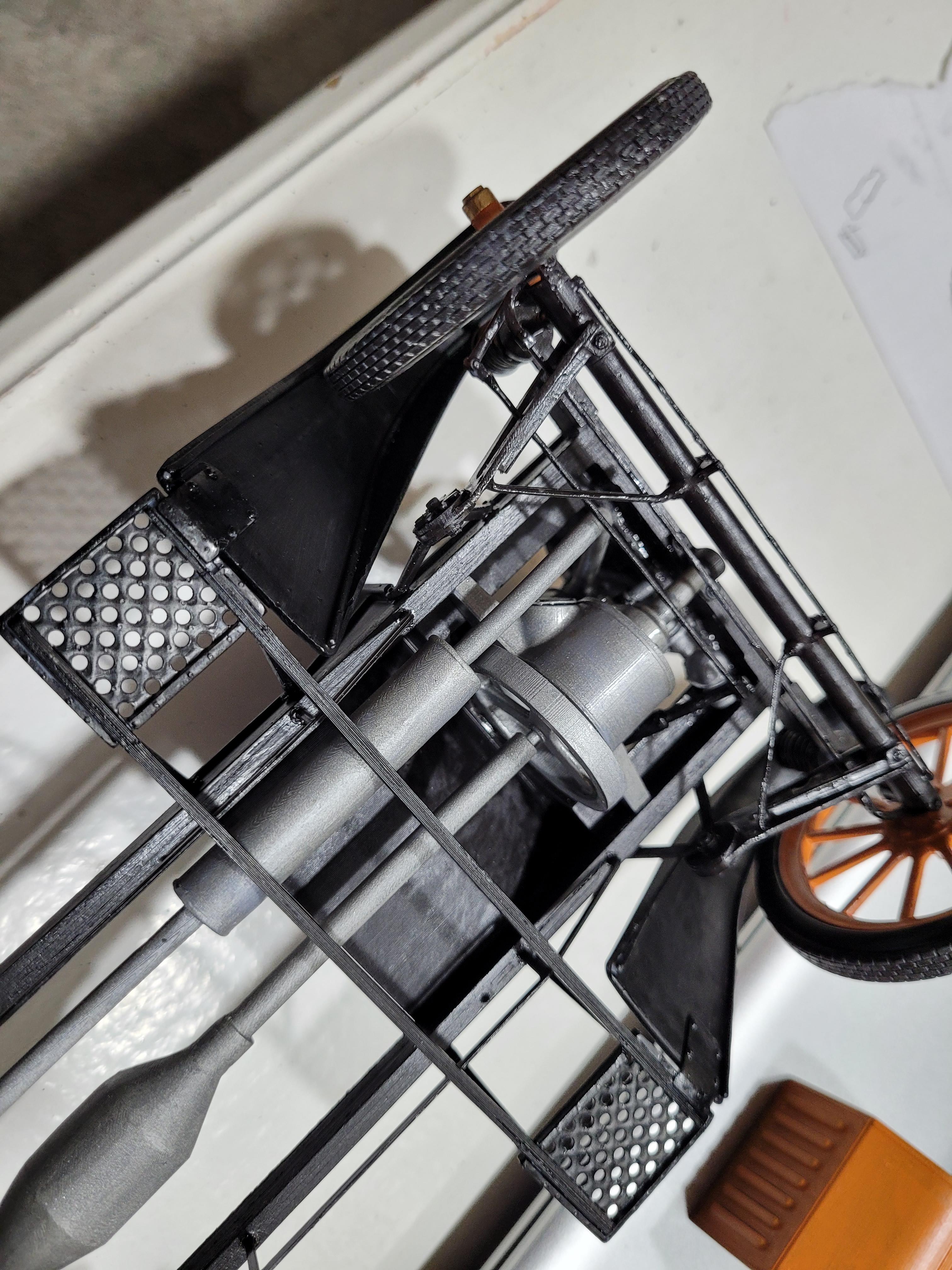
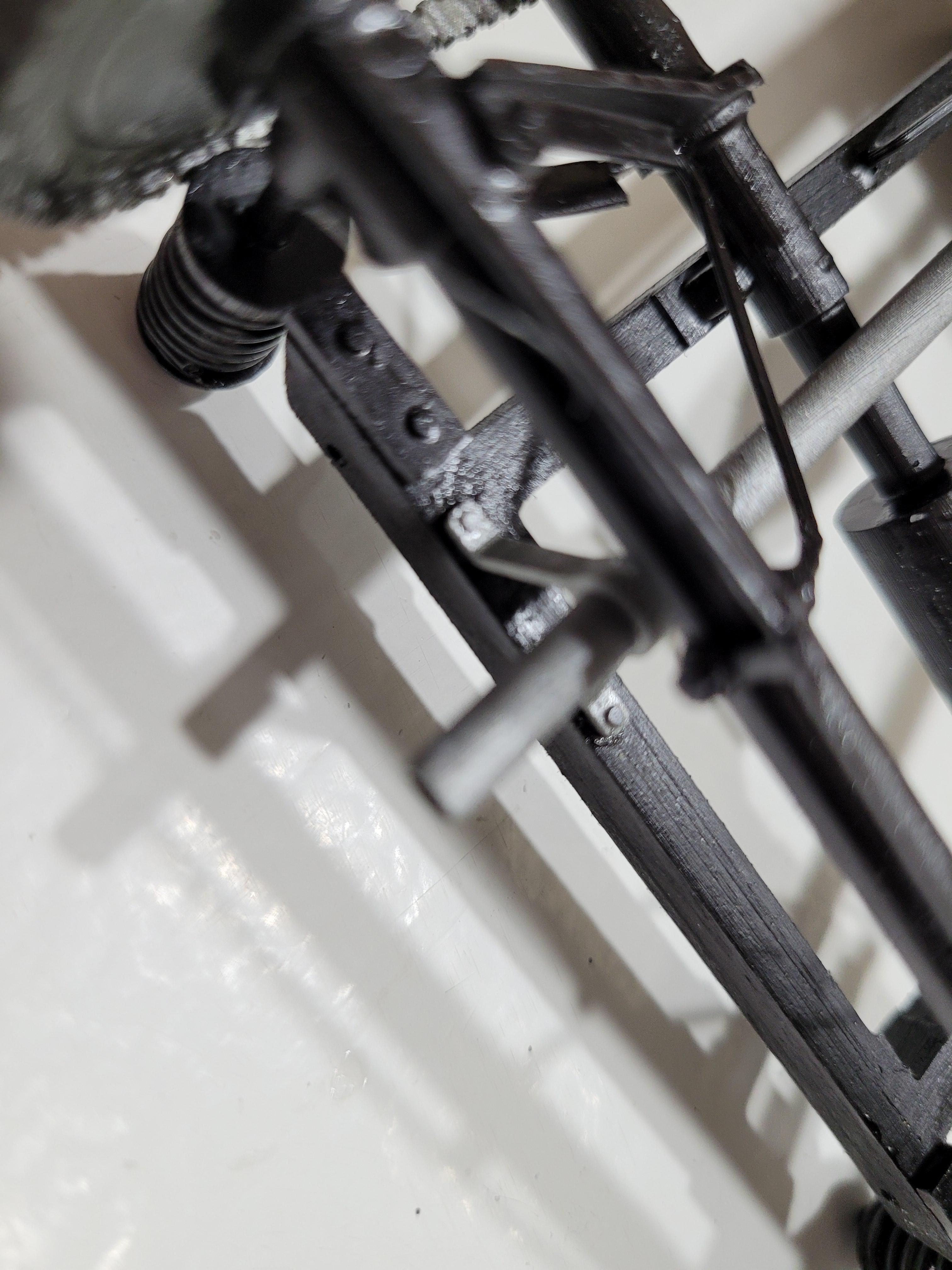
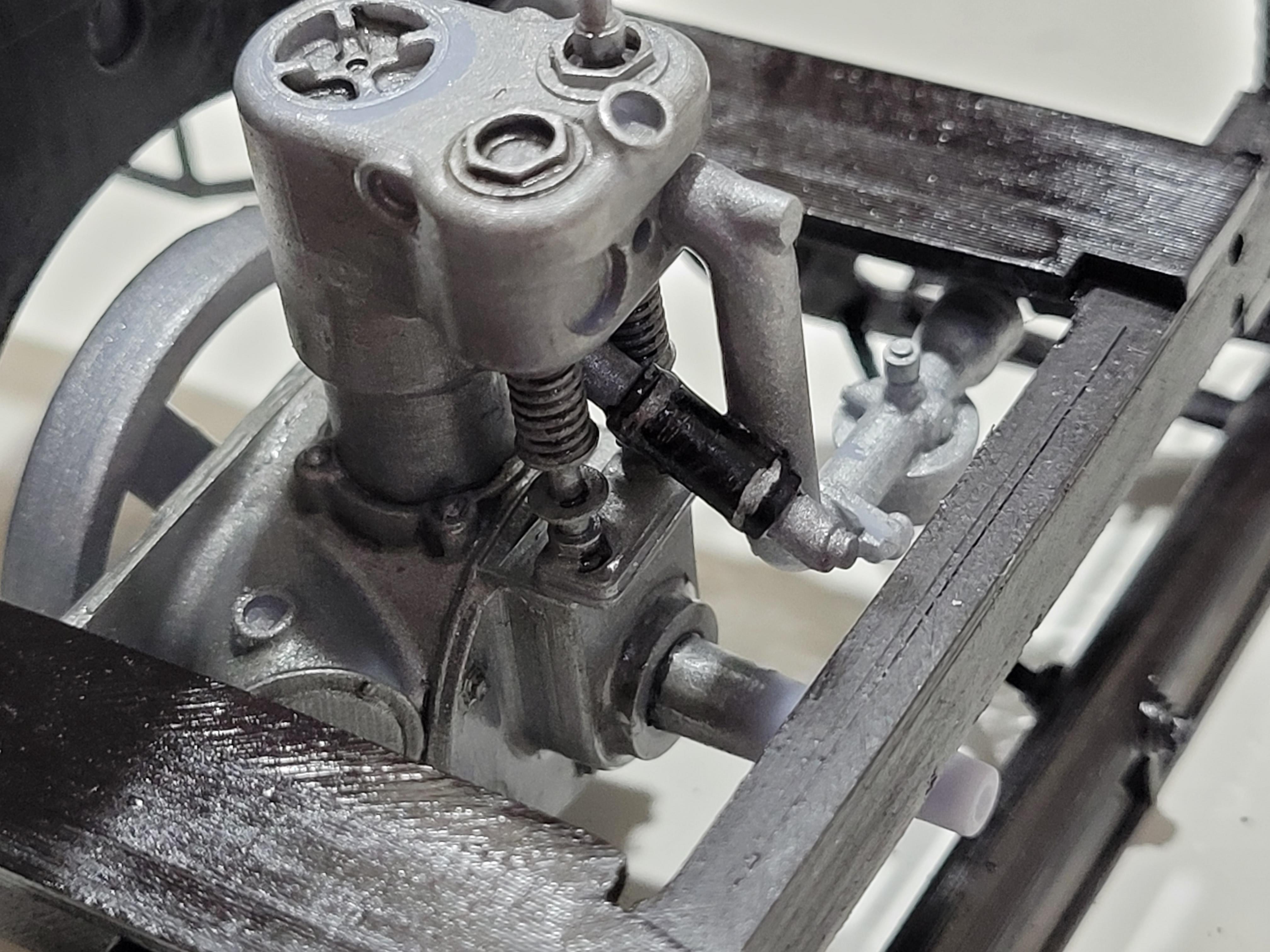
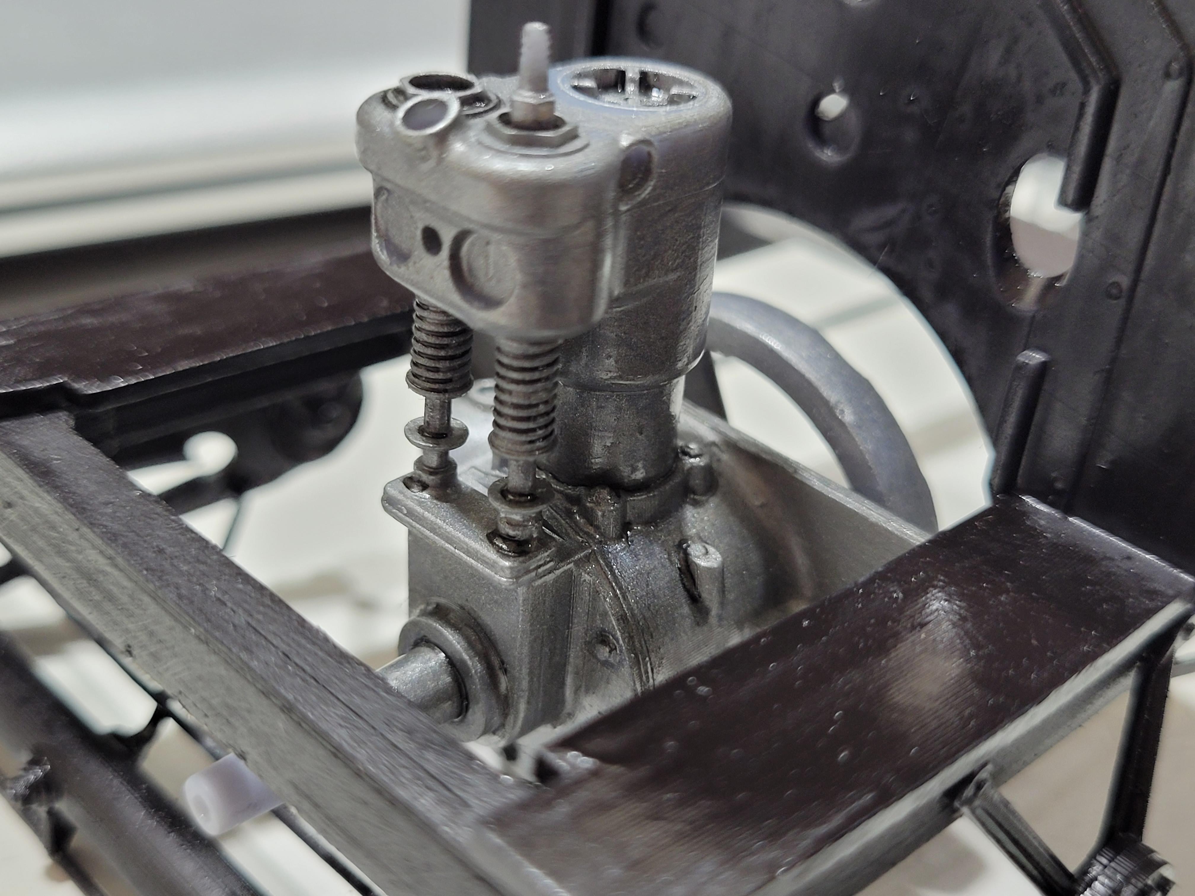
The vertical golf tee-looking thing is the oil filler tube. The tube is open at the top, but it does have a filter screen to keep larger particles out of the engine.
-
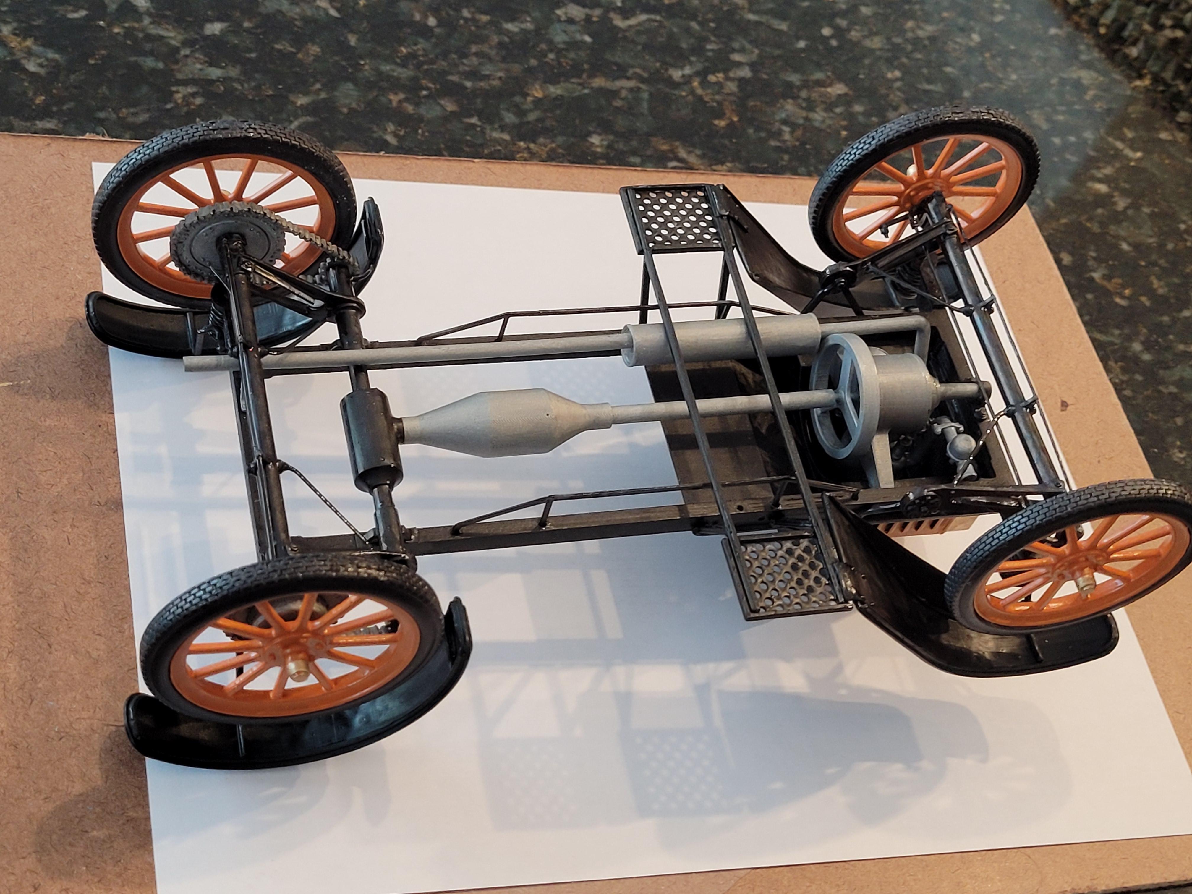
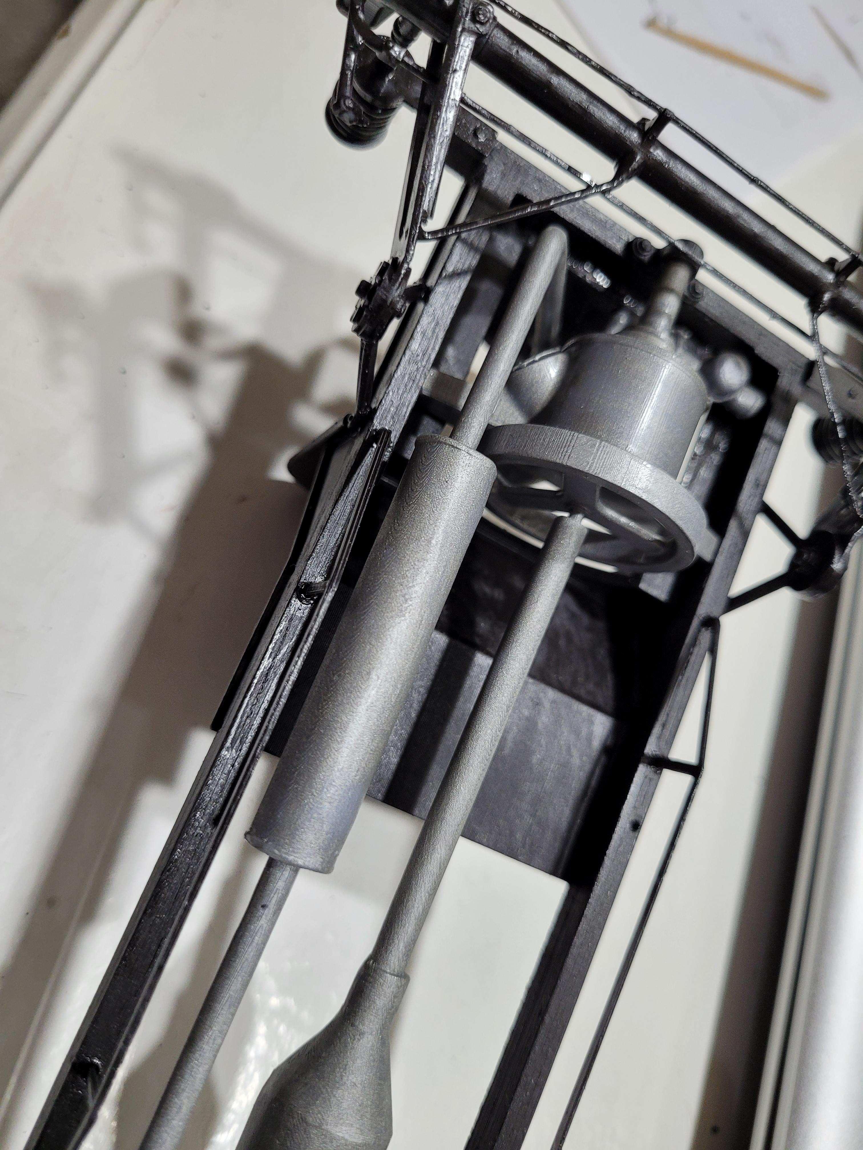
The driveshaft, exhaust pipe, muffler, tailpipe and bracket. Note the t-bracket that compresses the intake and exhaust pipes to the head.
-
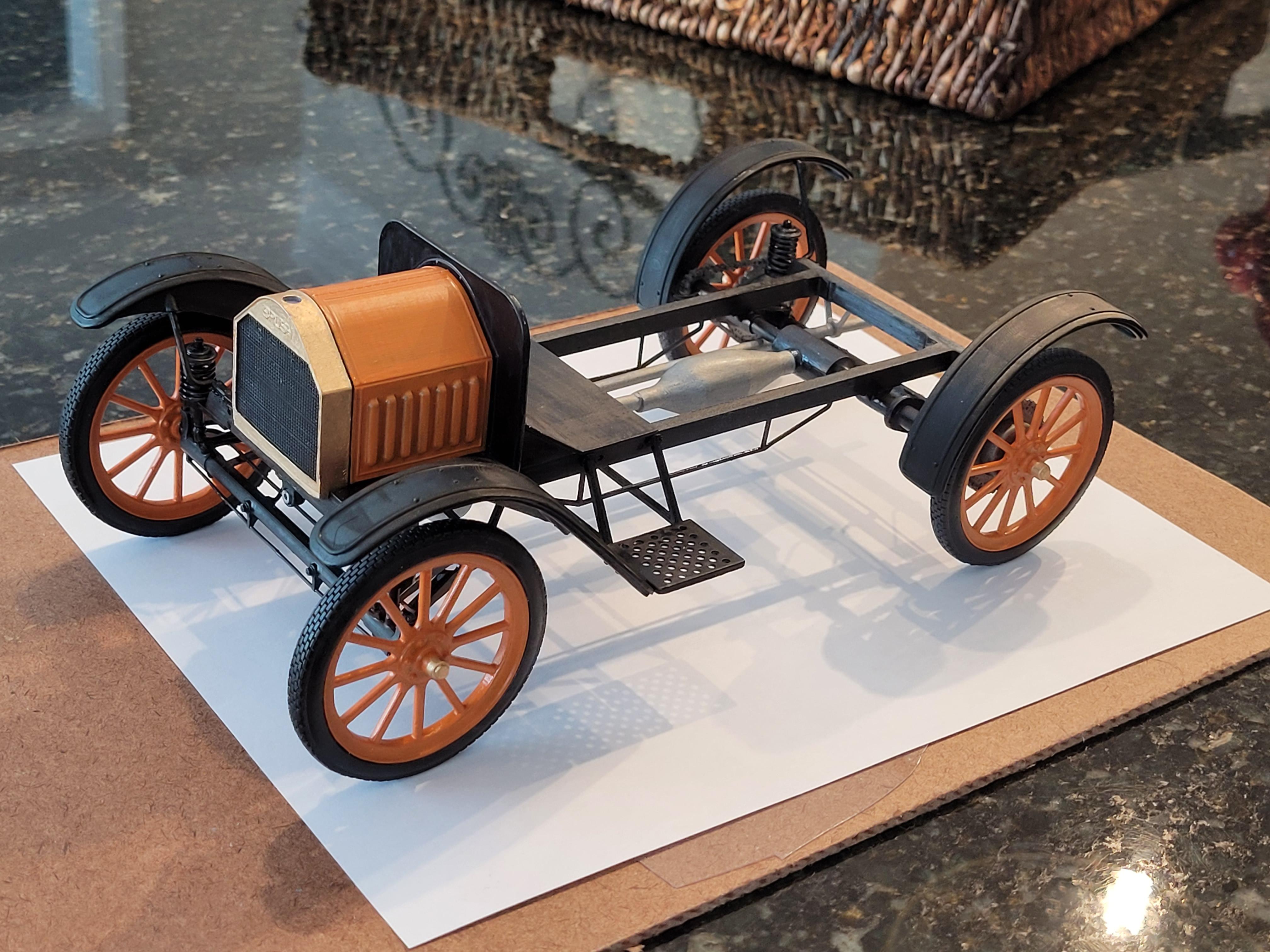
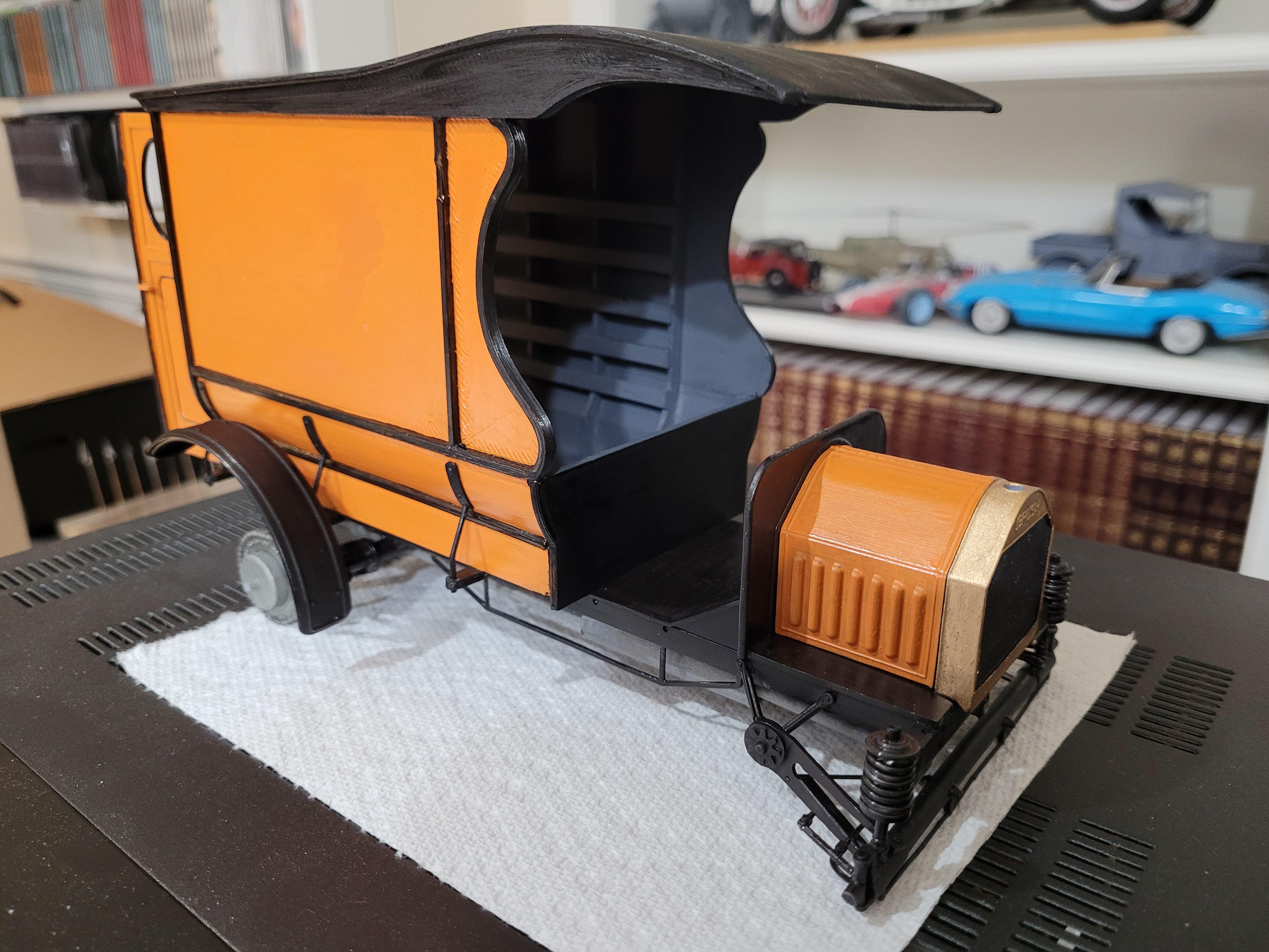
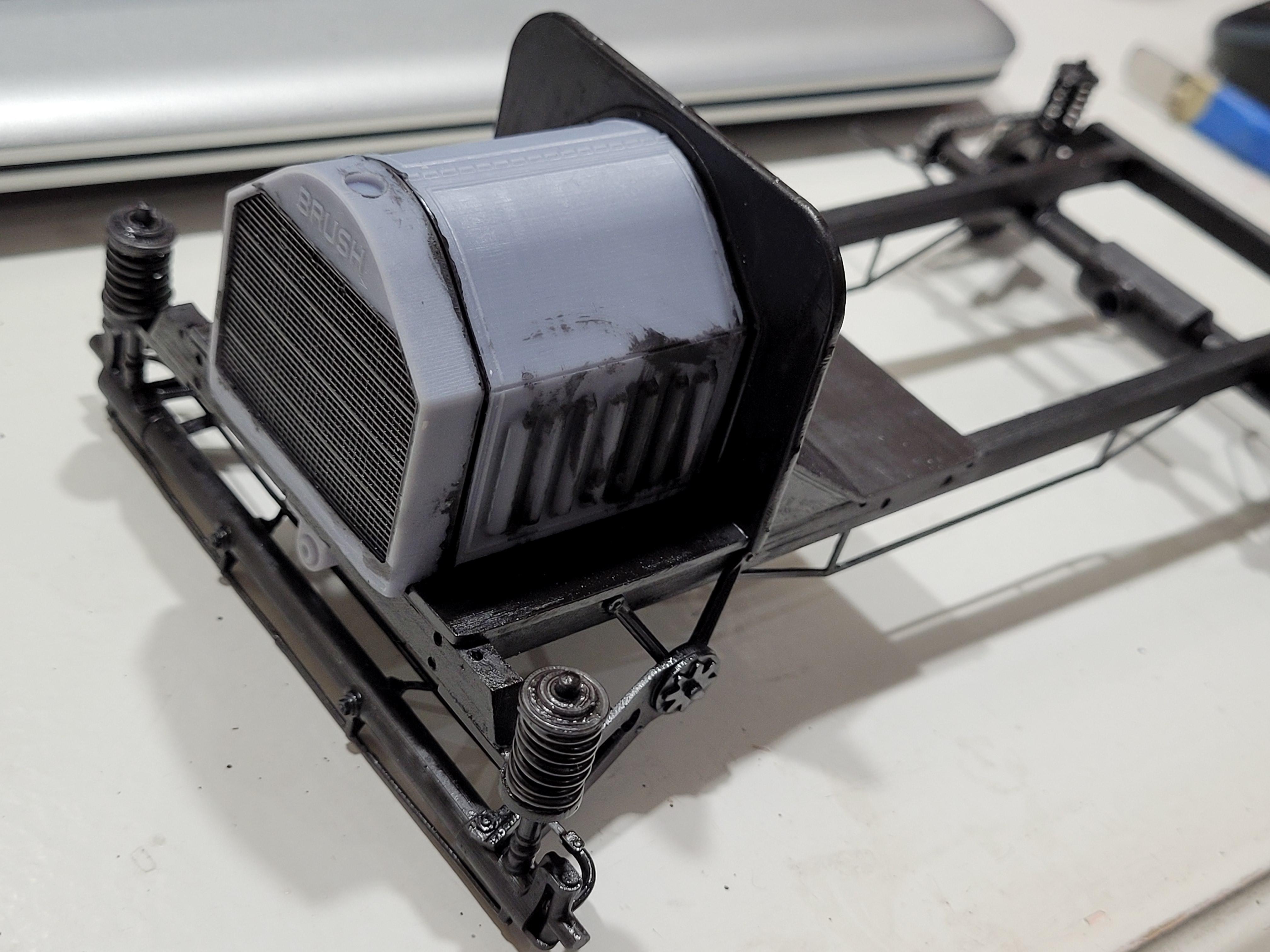
A preview of the final color. Rough at this point, but I like the color. I'm still looking for an appropriate business logo for the truck. Most likely a lumber company.
-
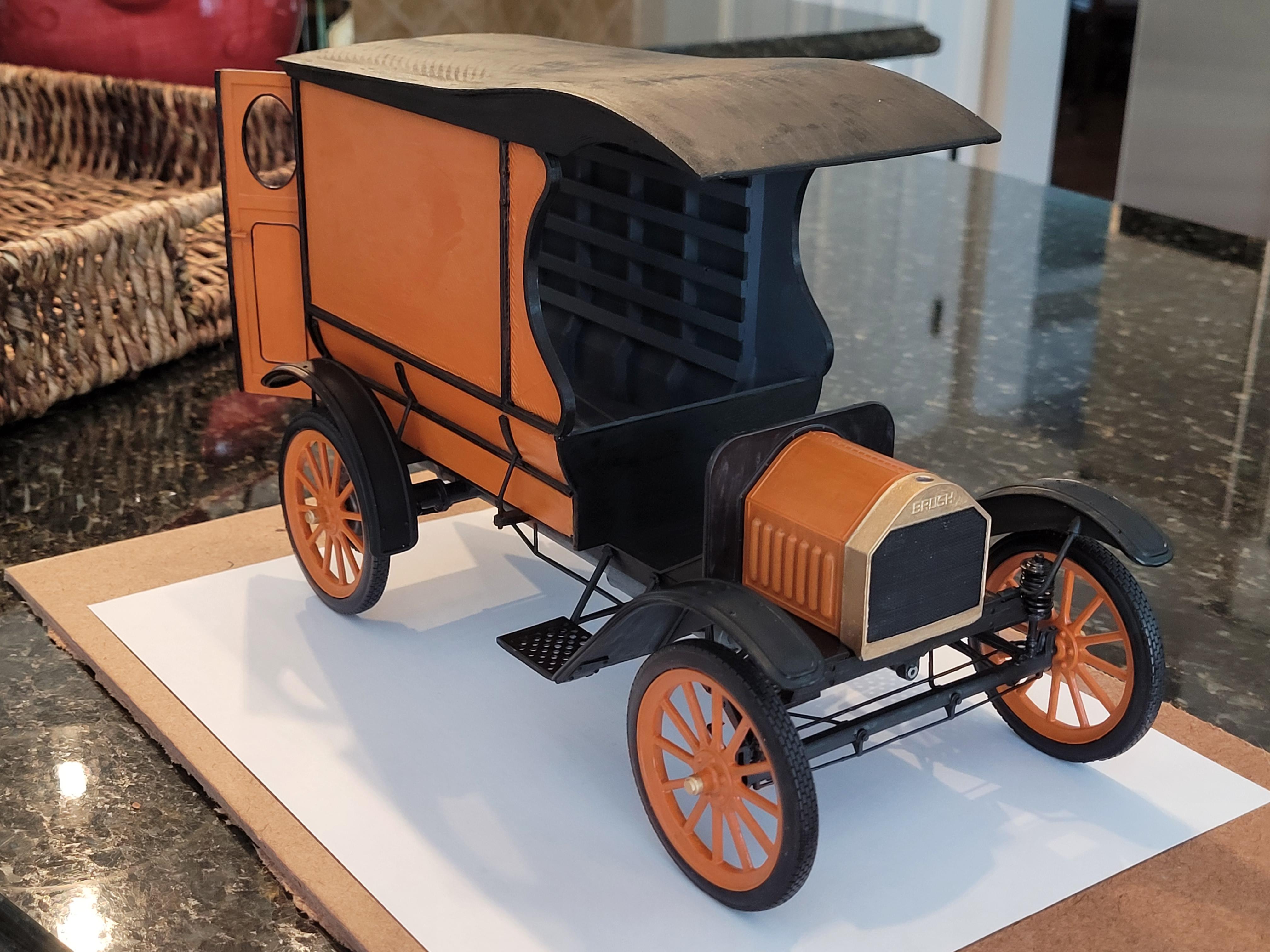
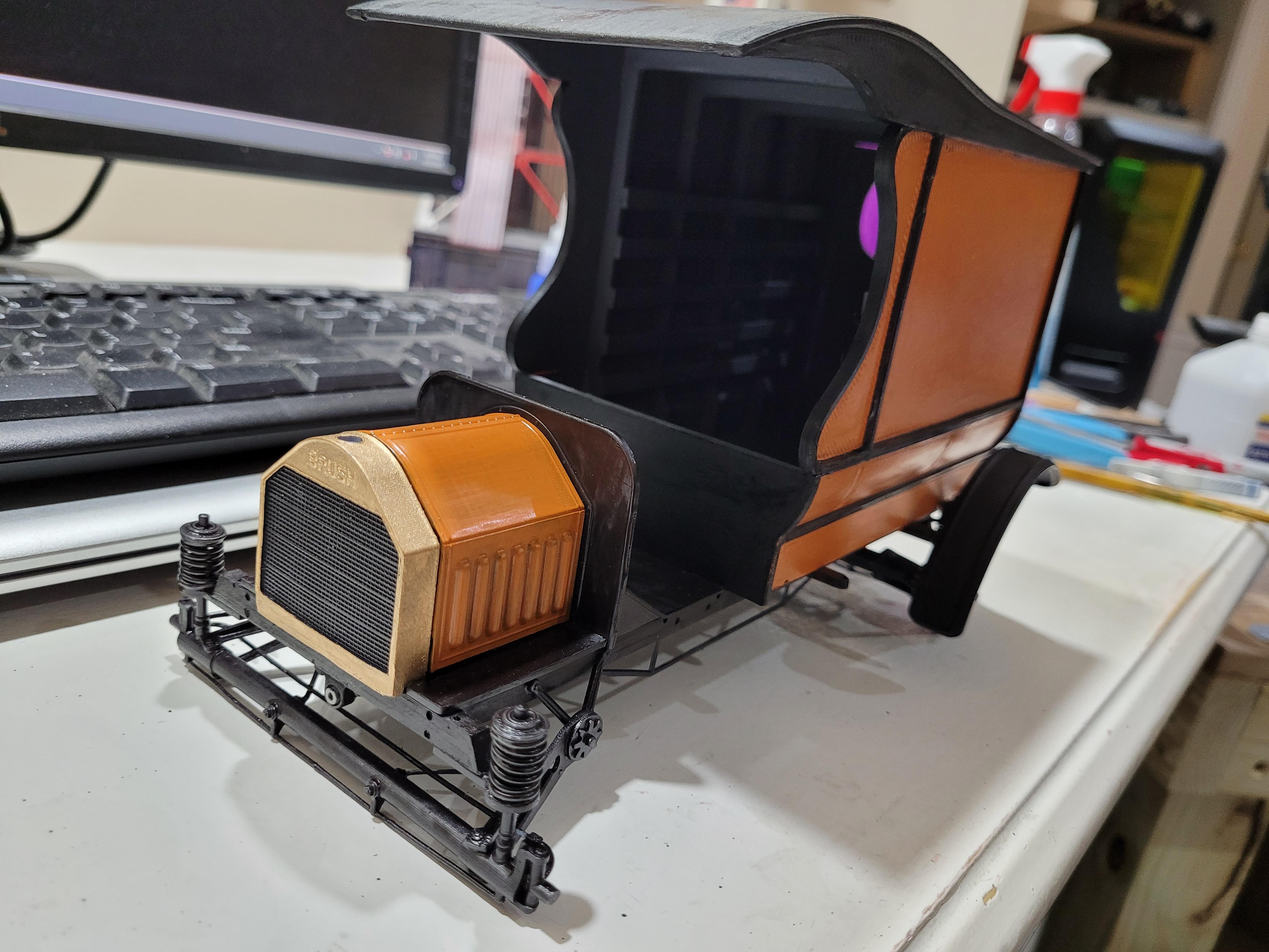
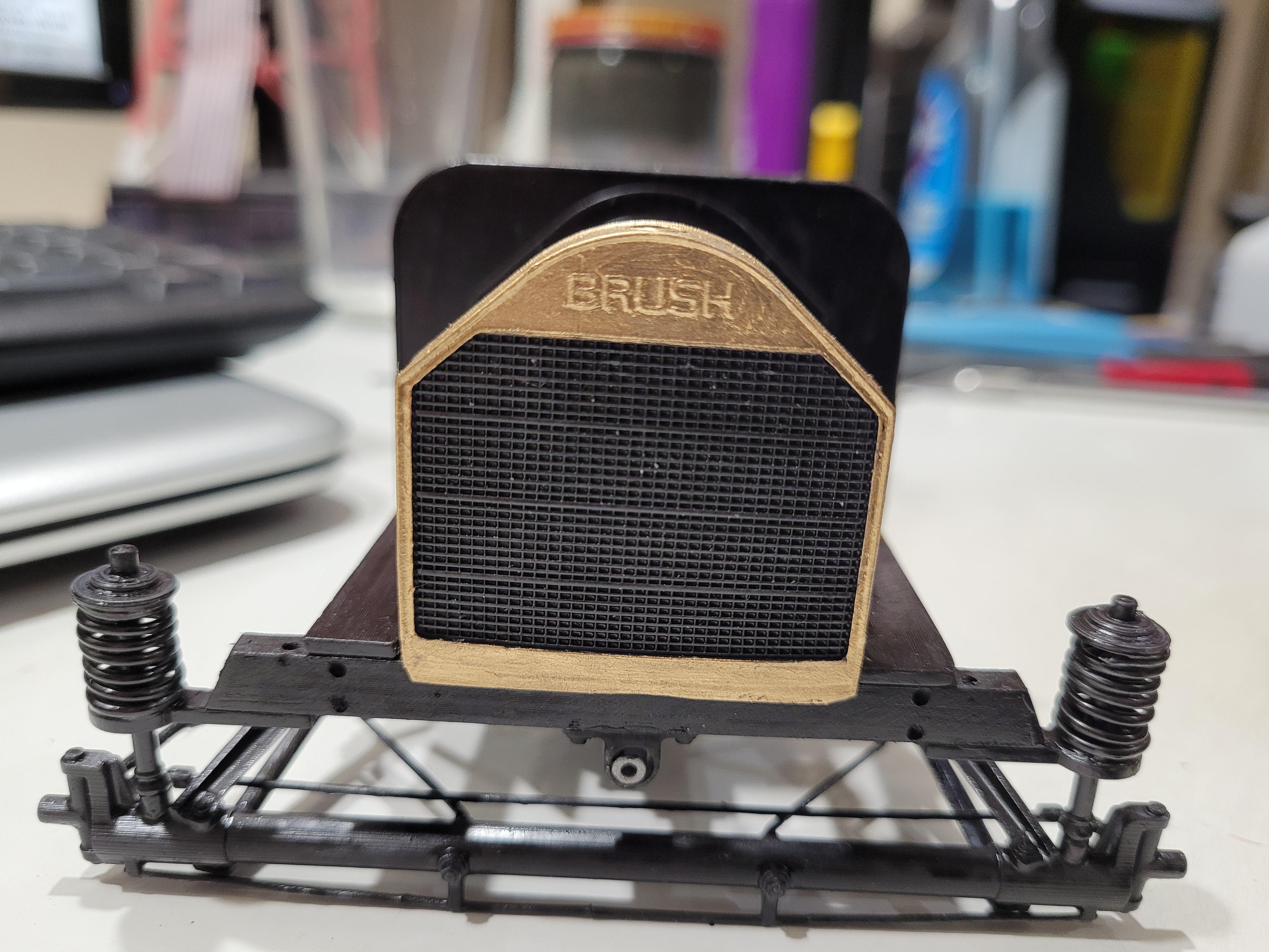
The "BRUSH" logo is stamped into the radiator shell, as depicted here.
-
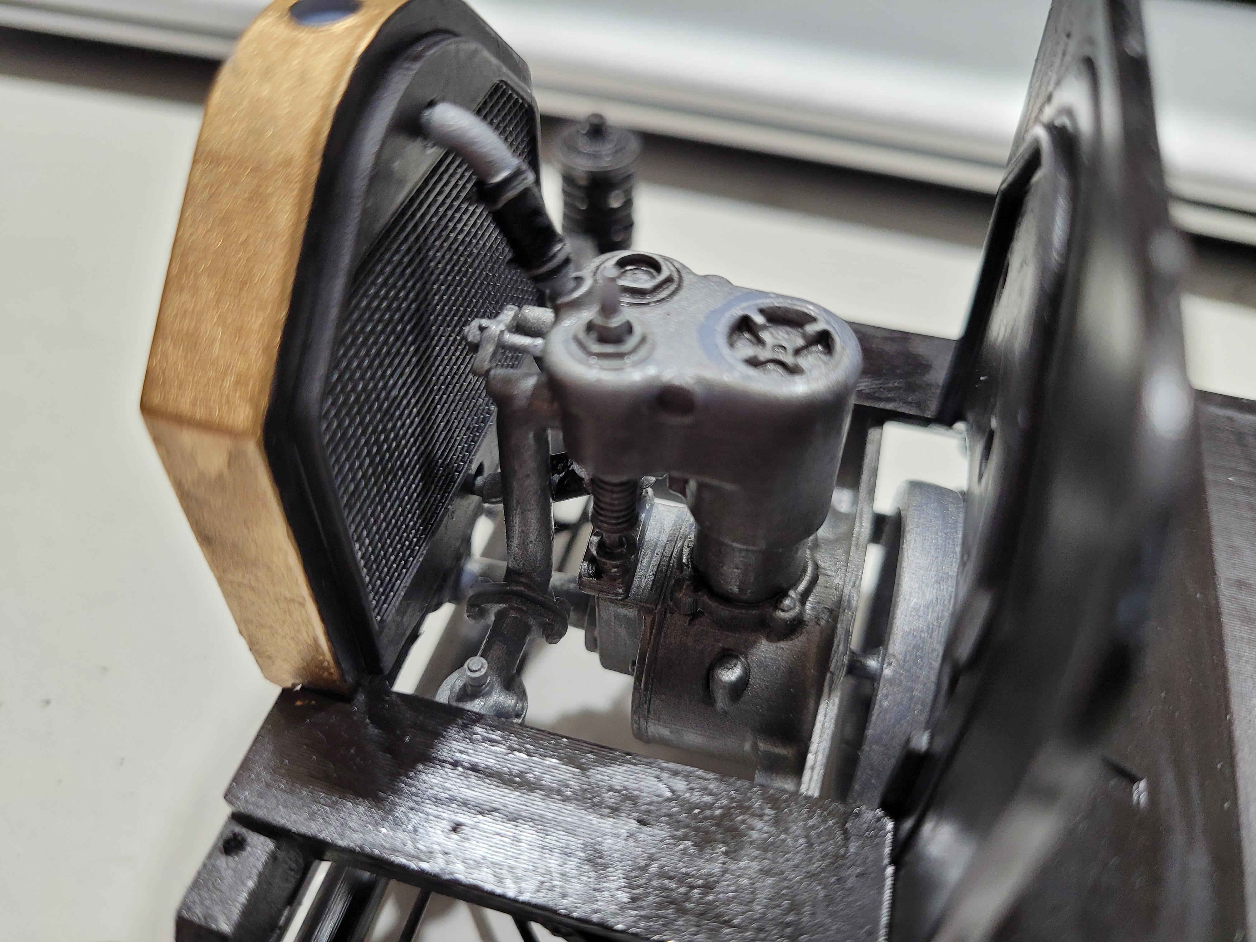
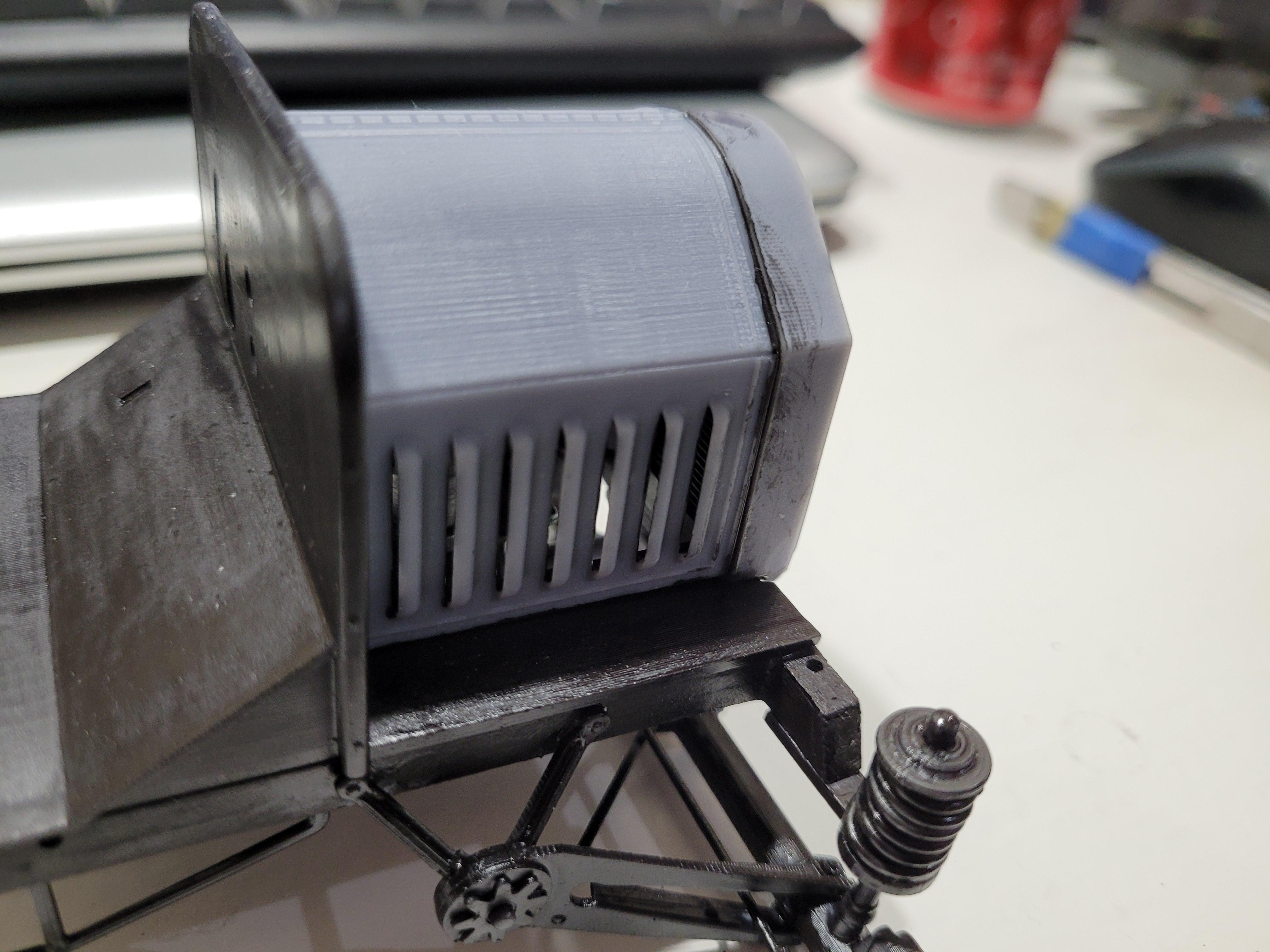
Upper radiator hose attached. The hood is used as a locating guide to make sure the radiator is properly set. This also ensures the the hood fits tightly between the cowl and radiator.
-
Intake pipe, carb, and lower radiator hose.
-
Engine in place. There is a crank starter shaft bearing that will pull the engine back to a vertical position.
-
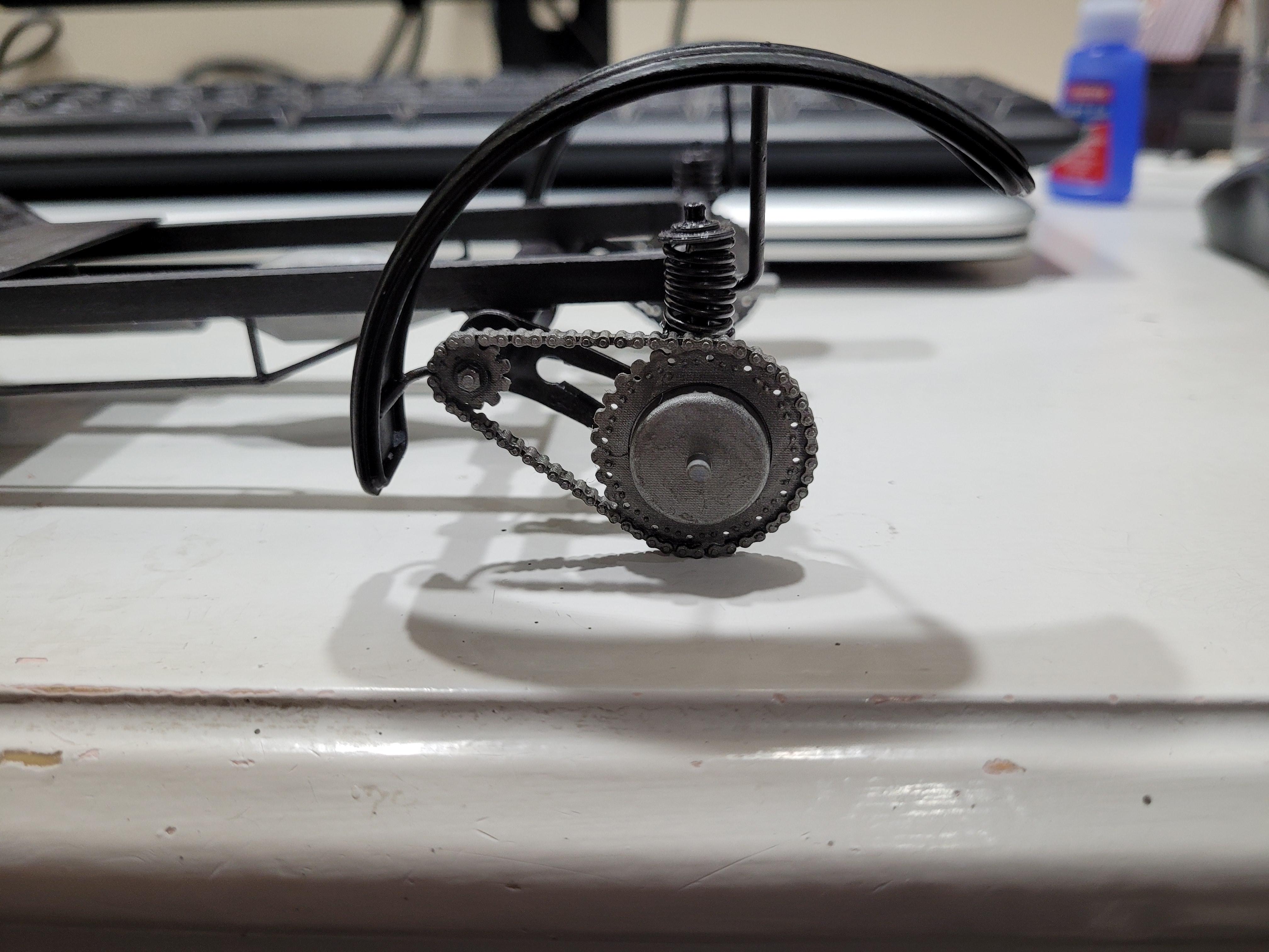
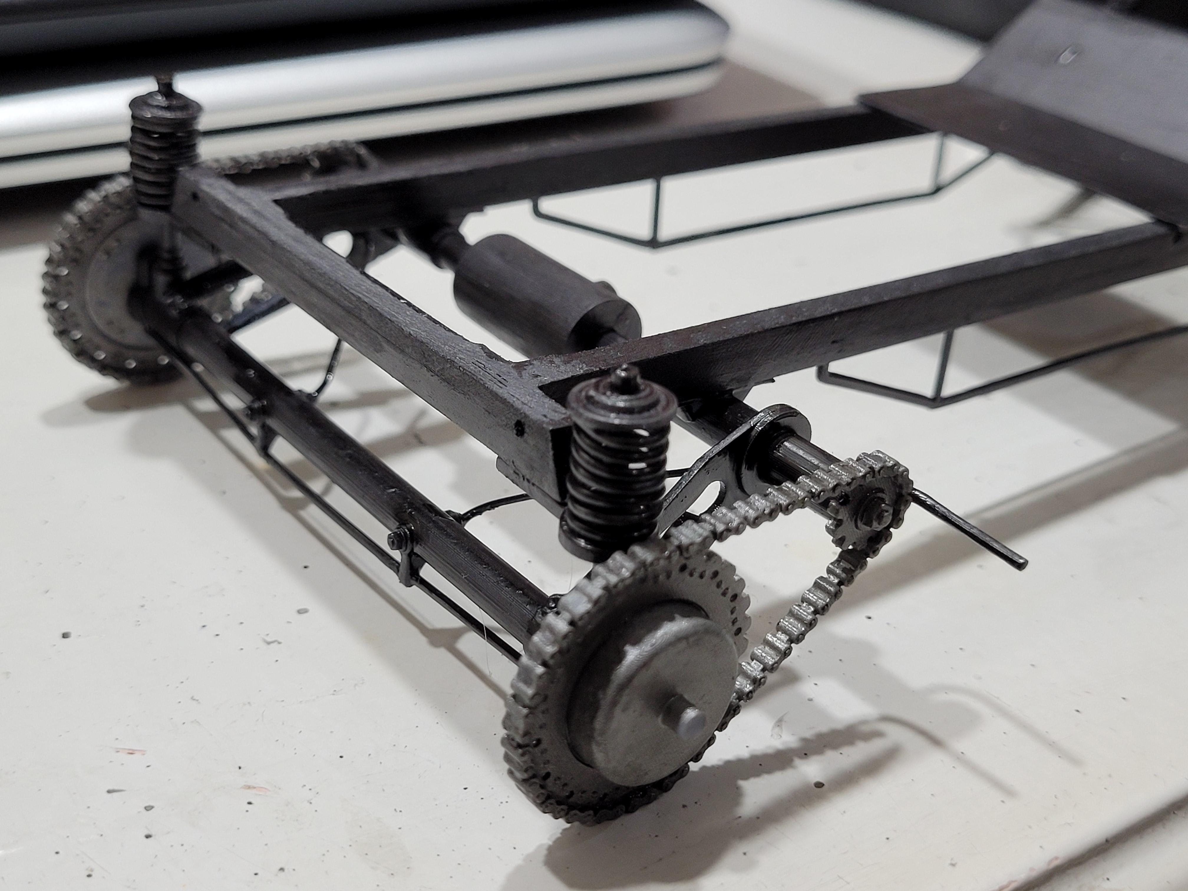
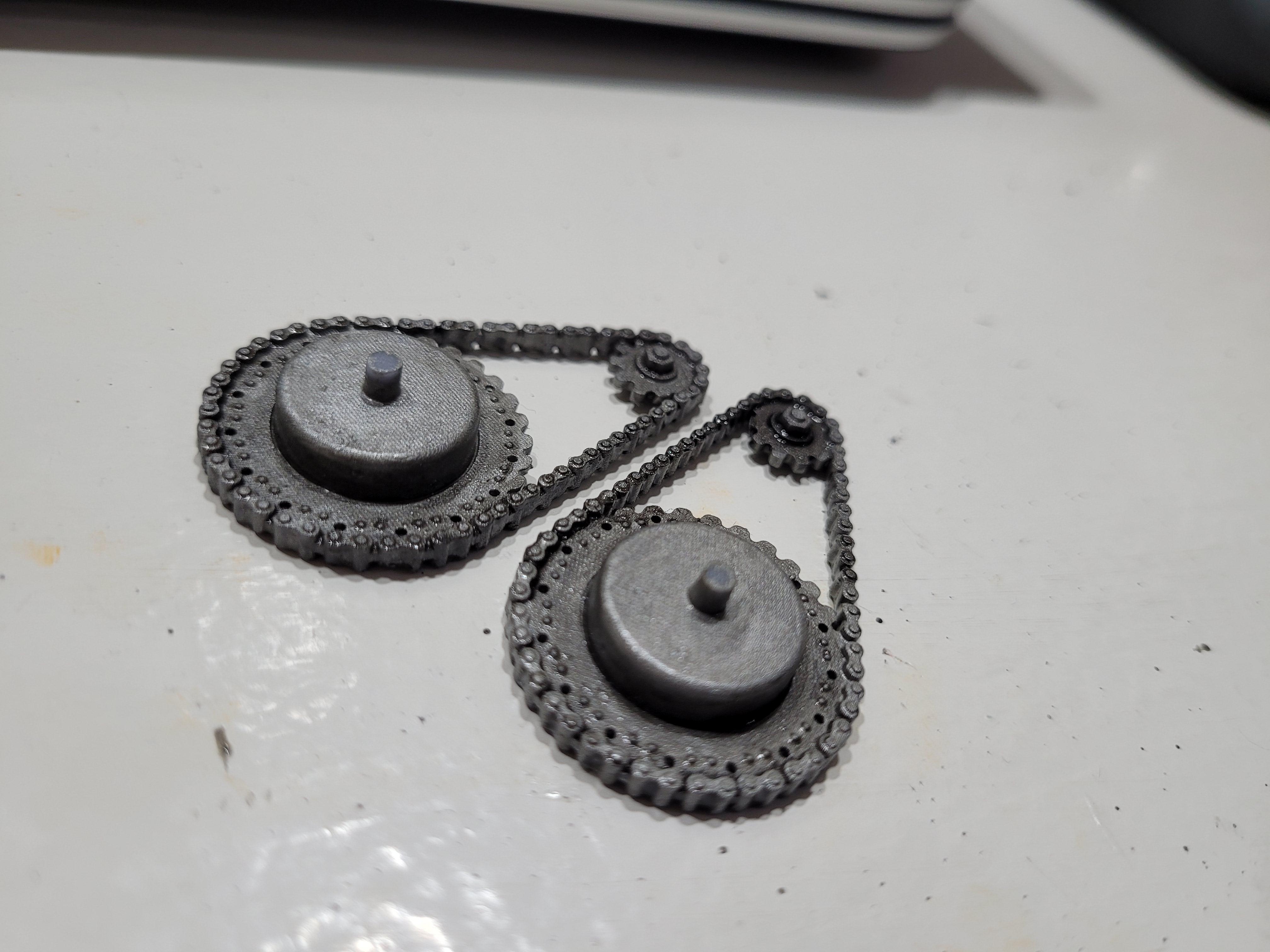
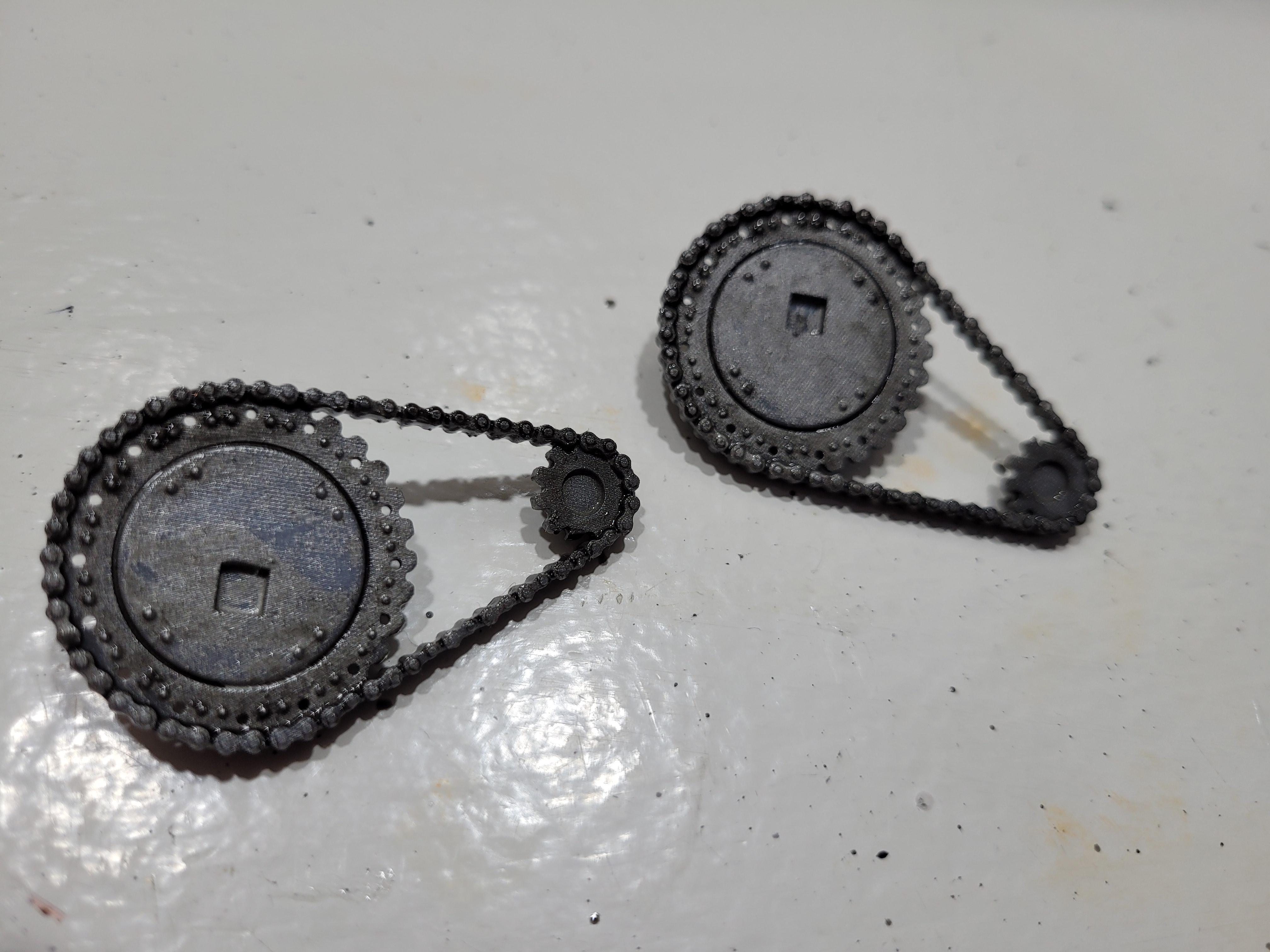
Drive chains glued to rear suspension.
-
The drive chains look pretty grimey!
-
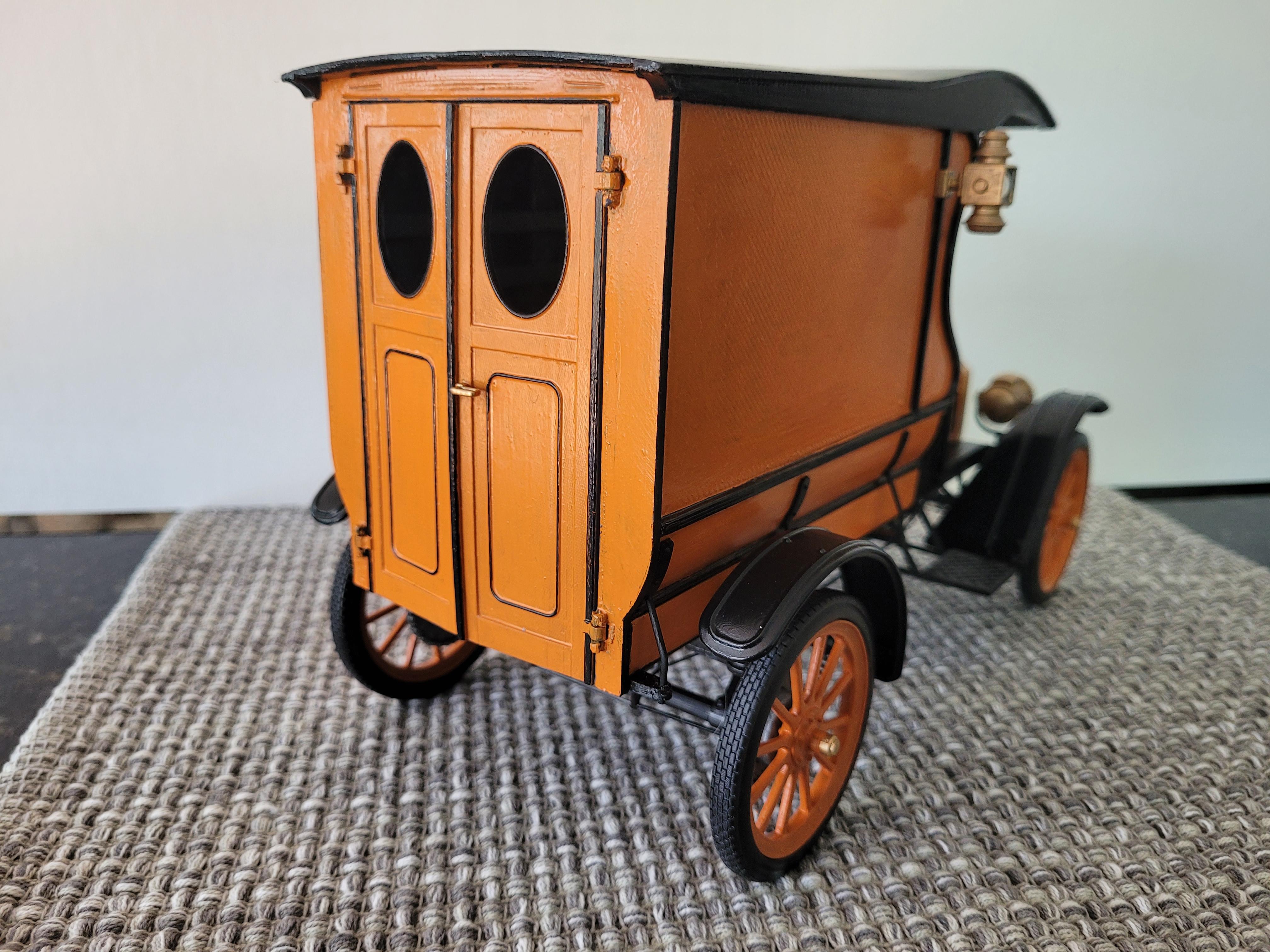
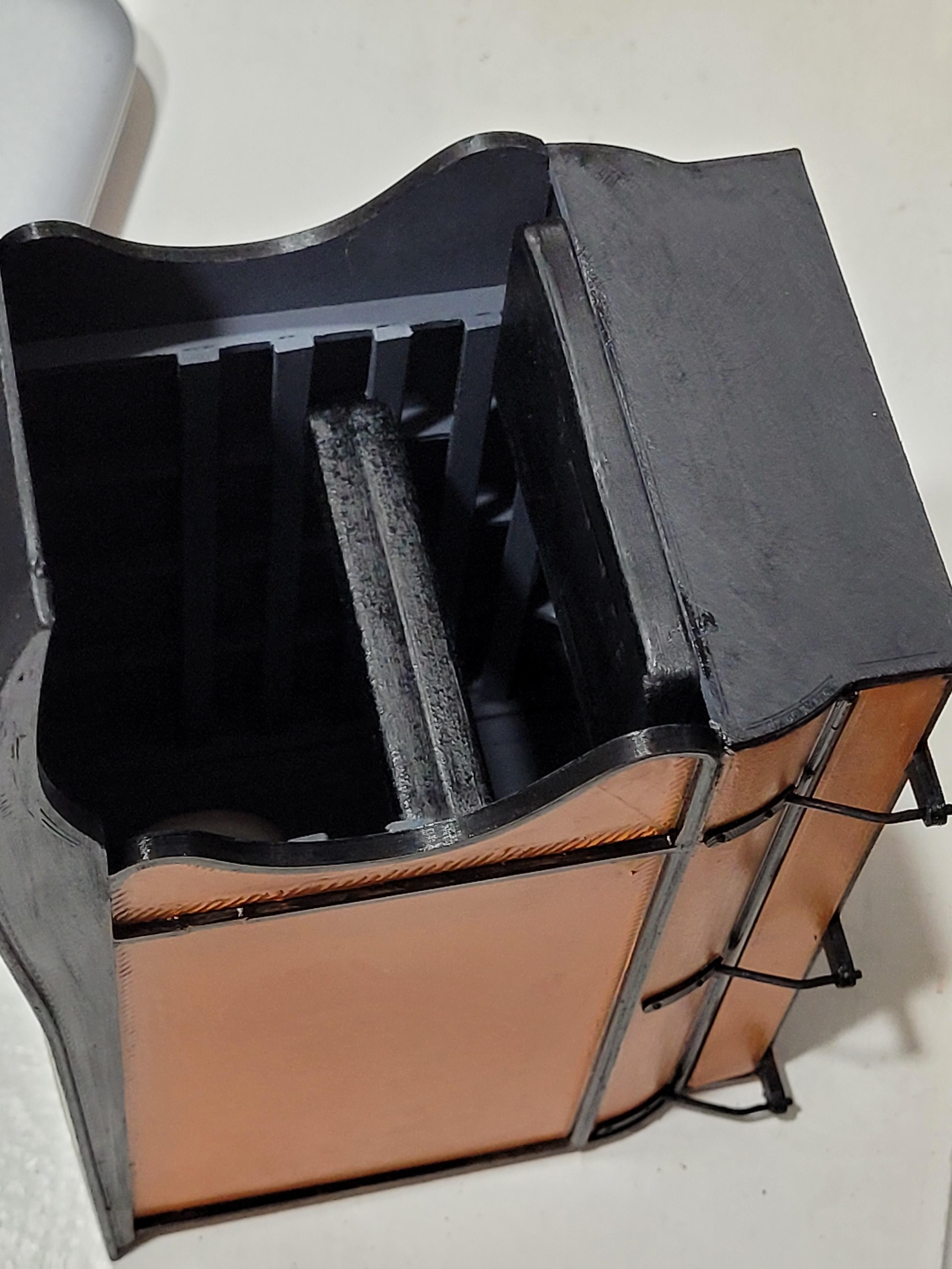
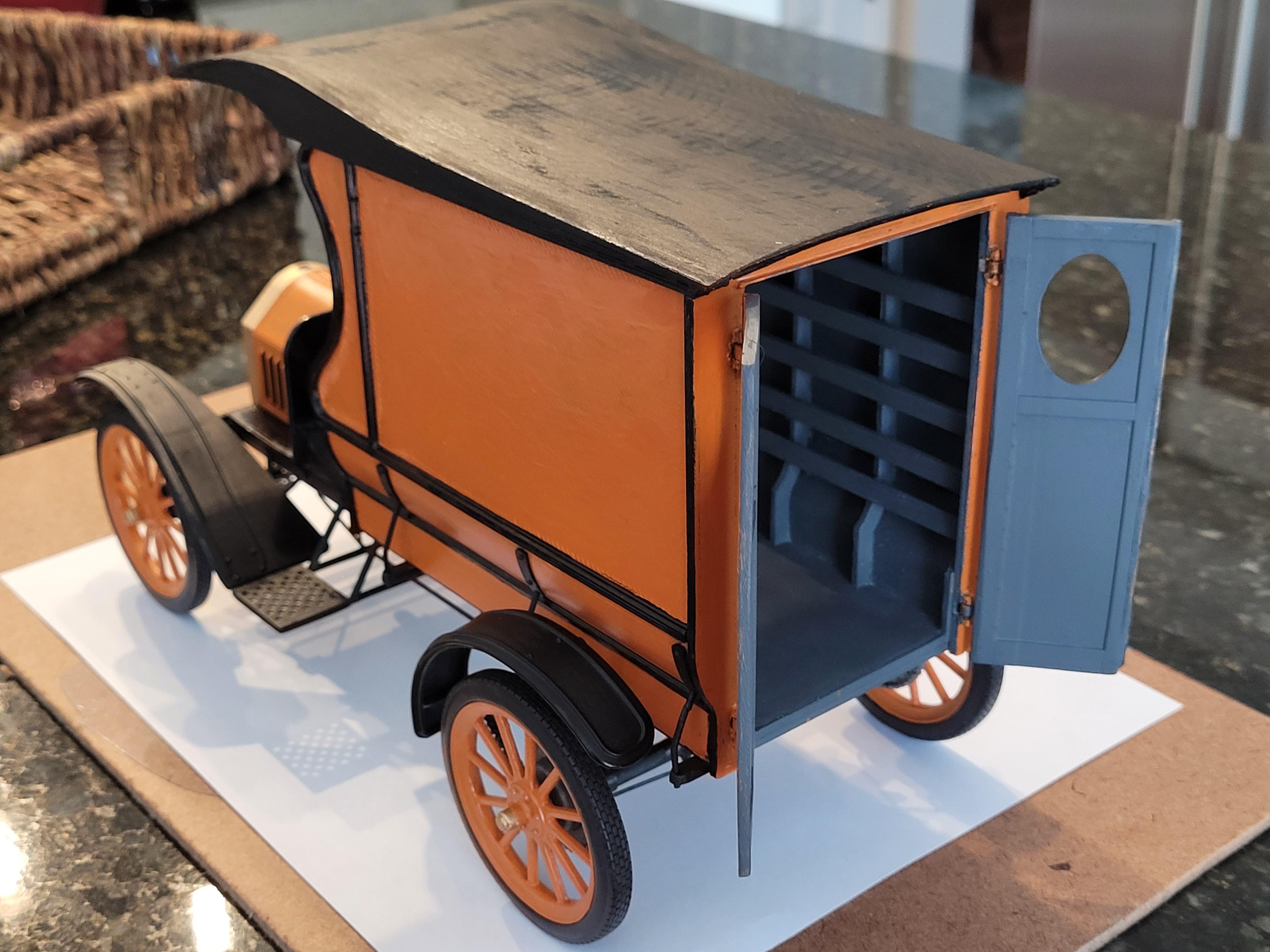
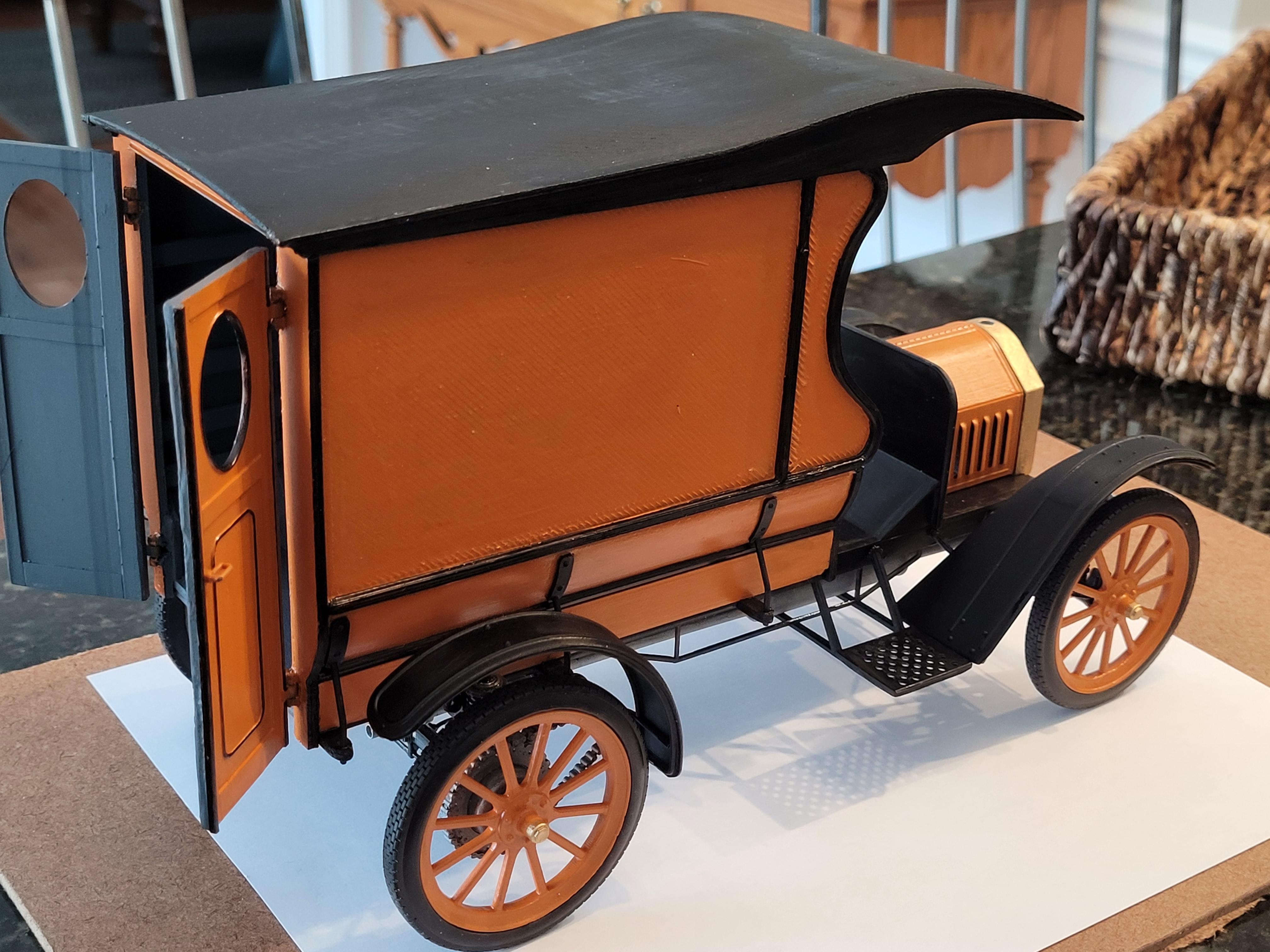
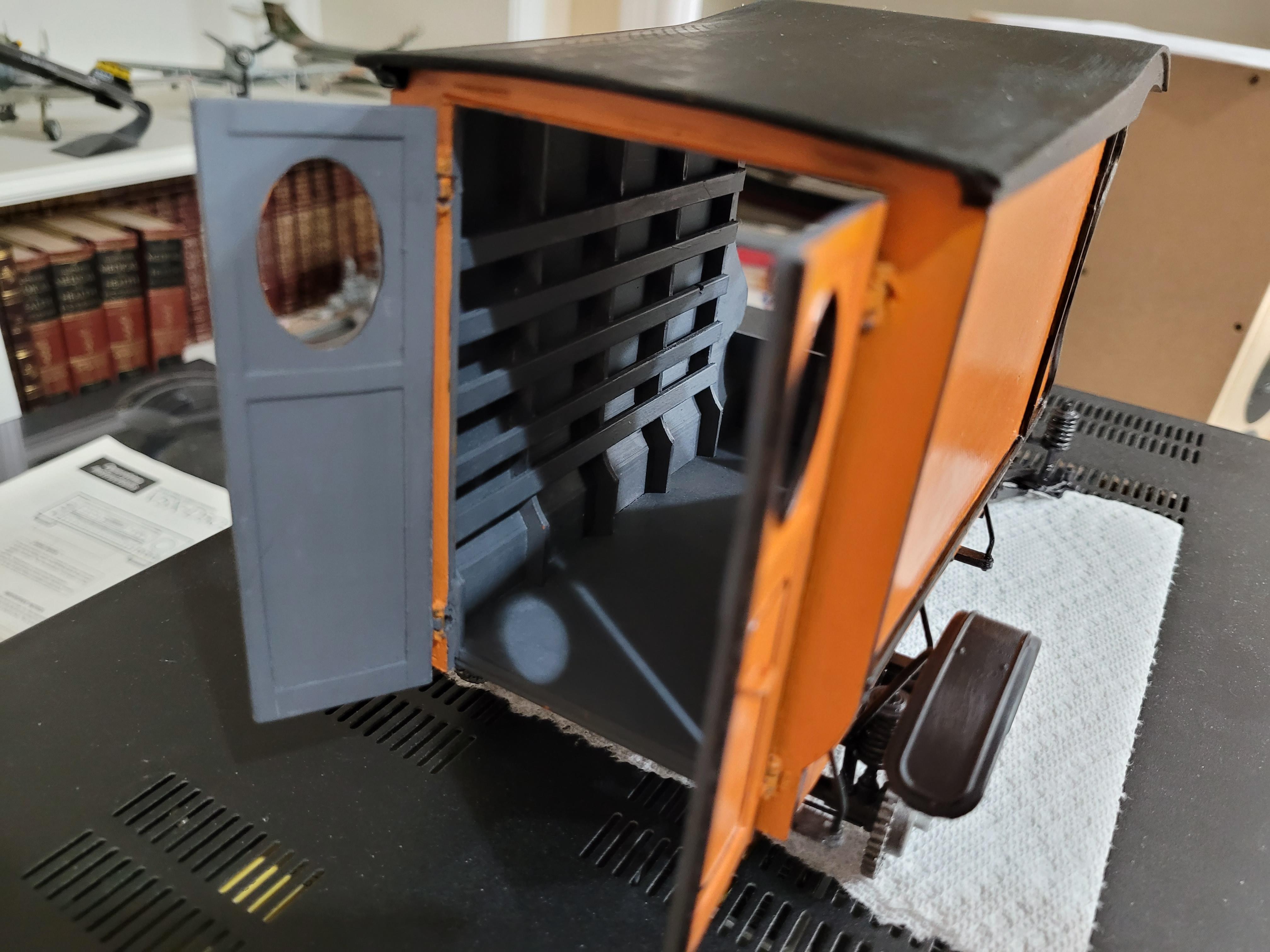
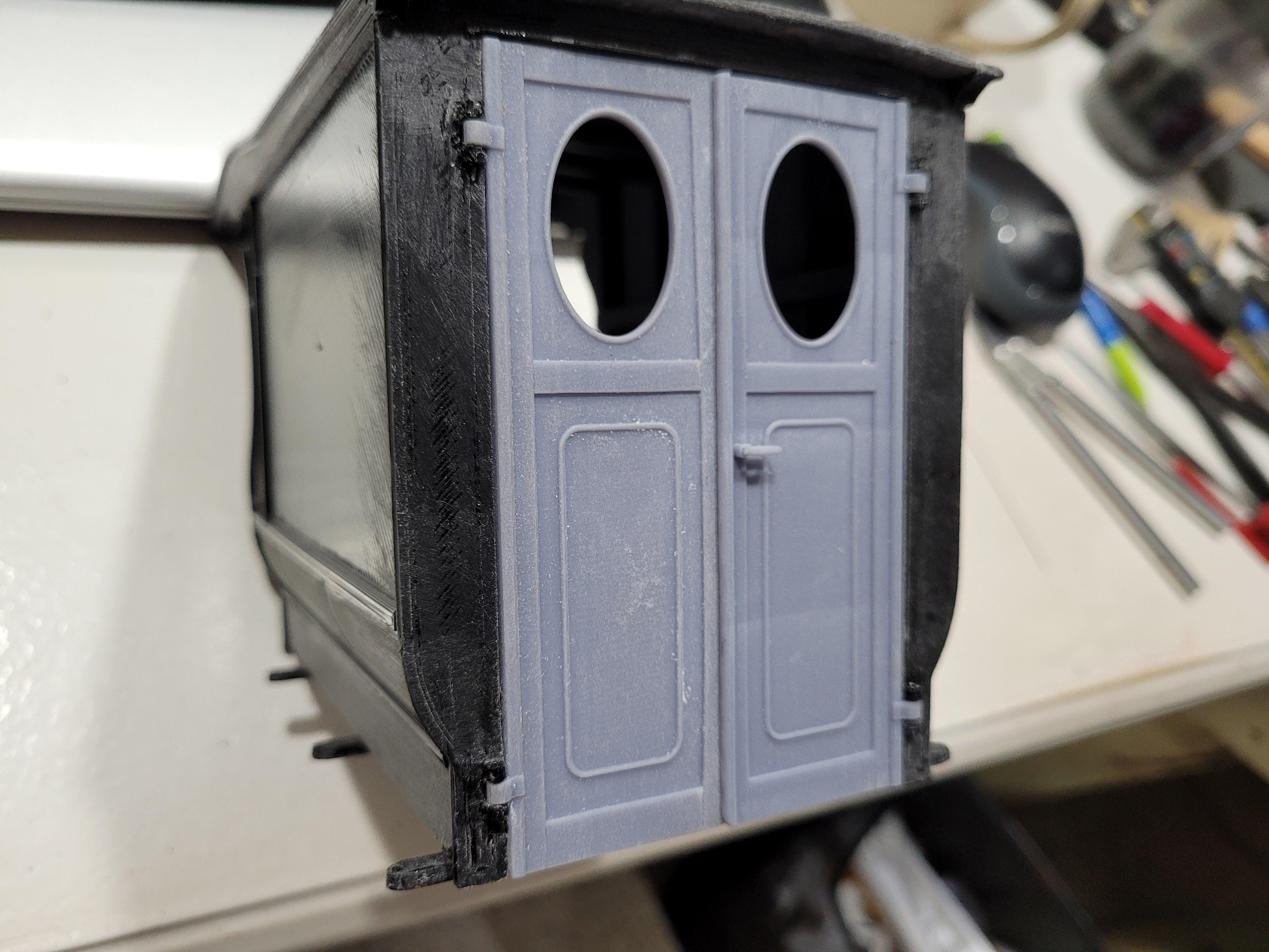
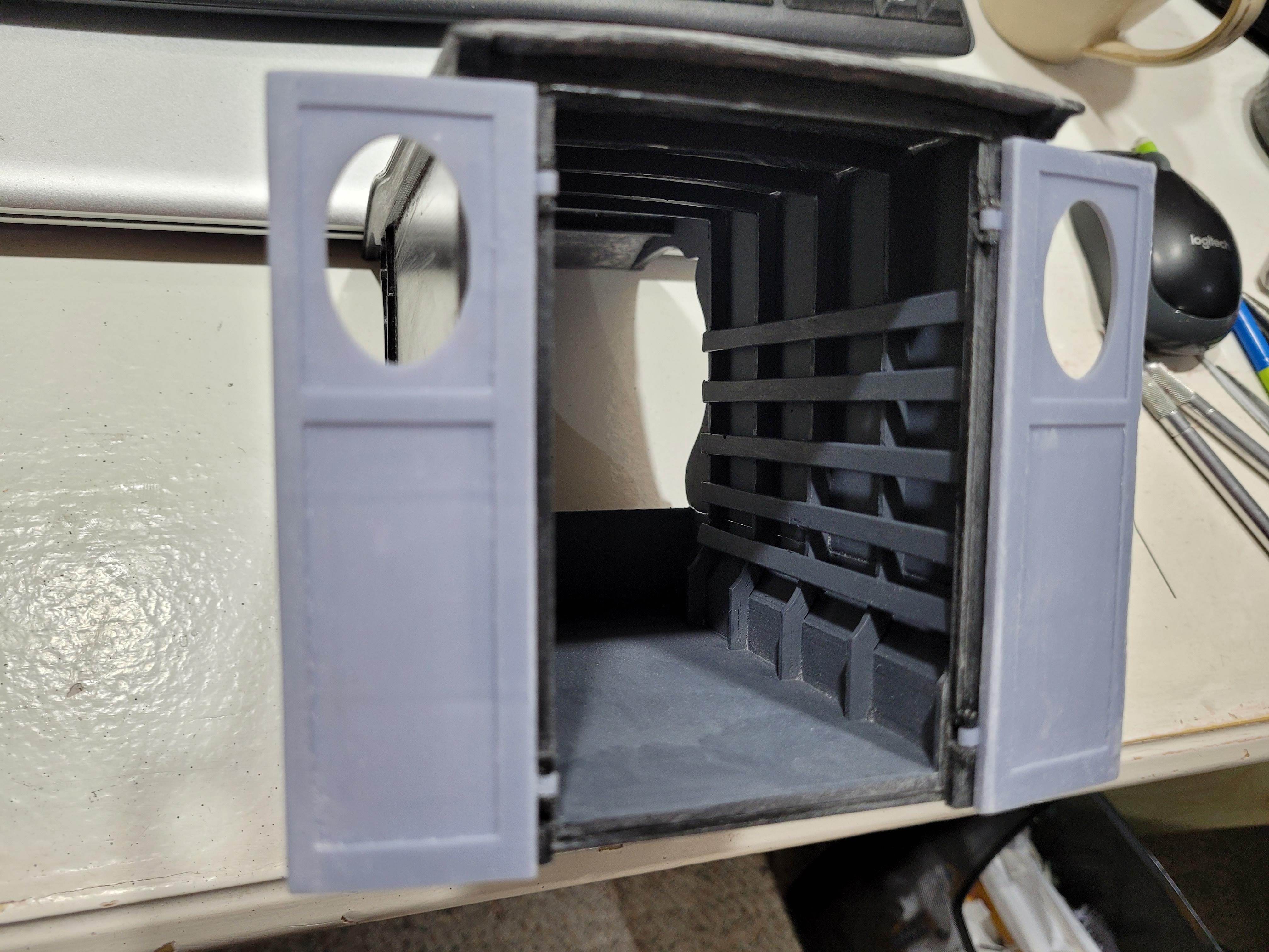
The rear cargo doors open and close. A lot of filing and grinding to get them parallel and tight when shut.
-
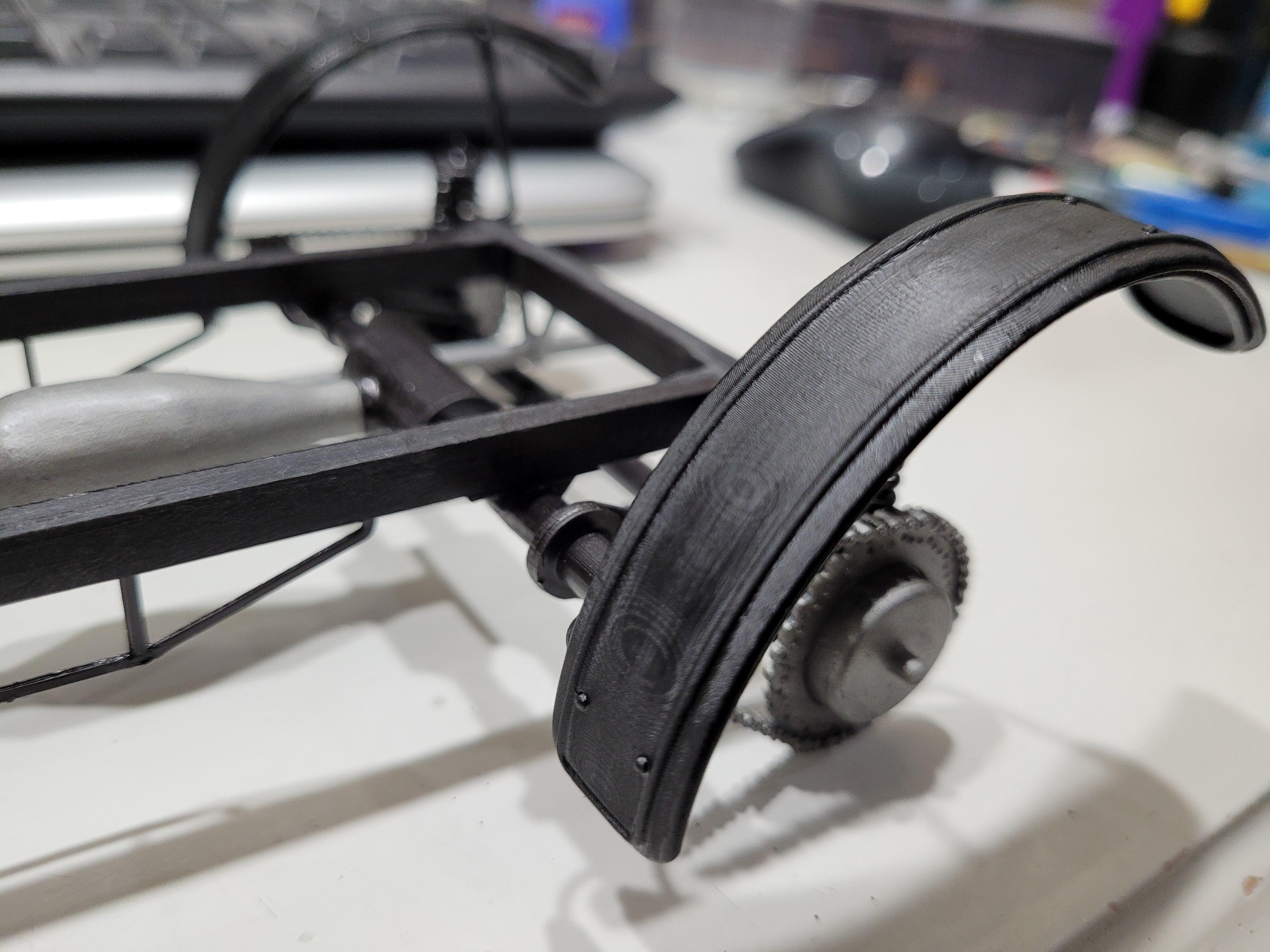
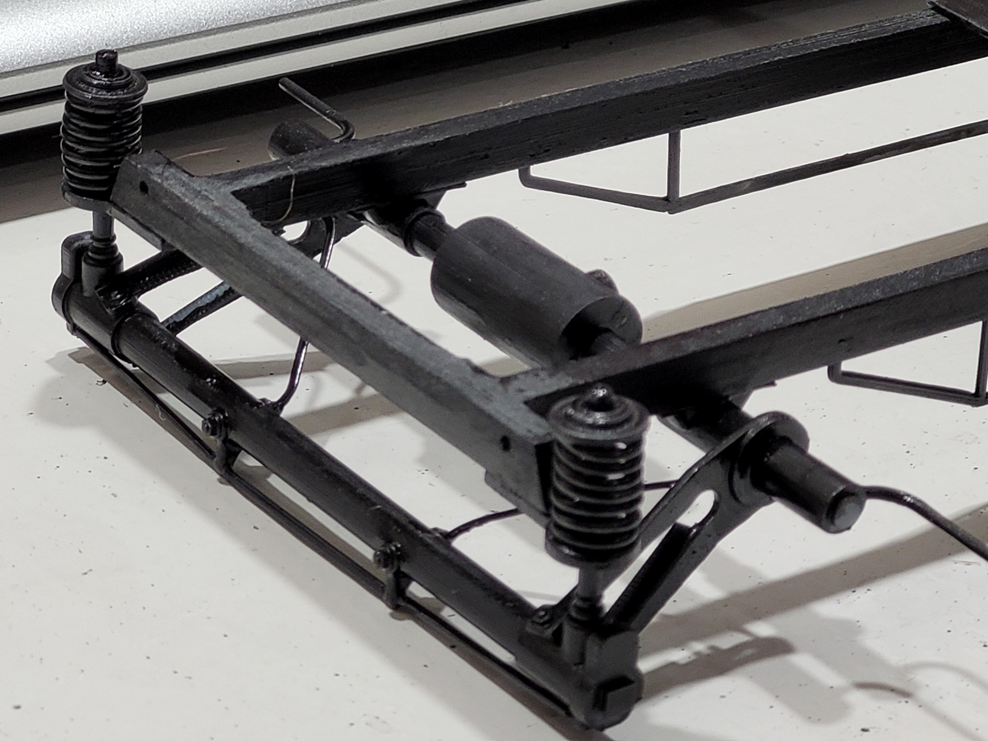
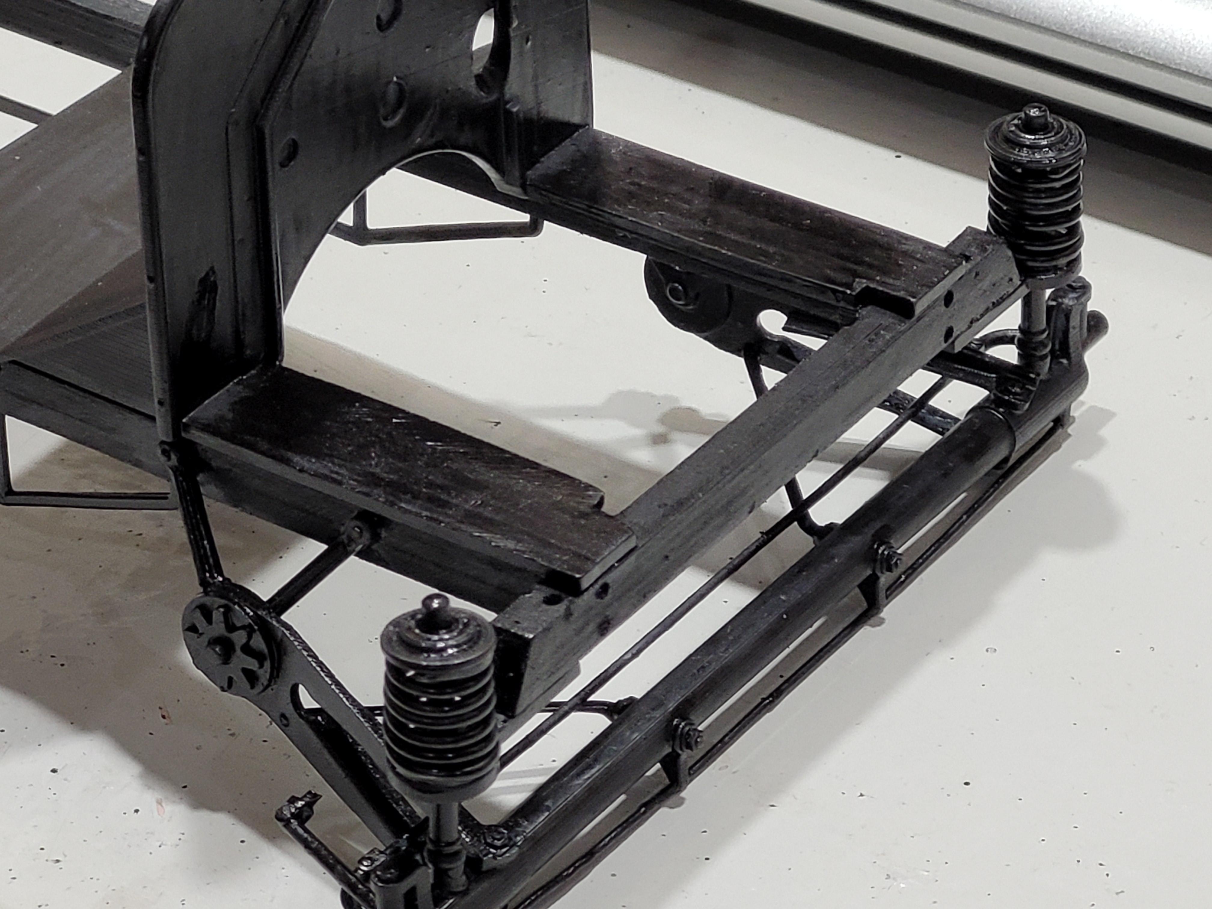
The four-corner extension springs in place.
-
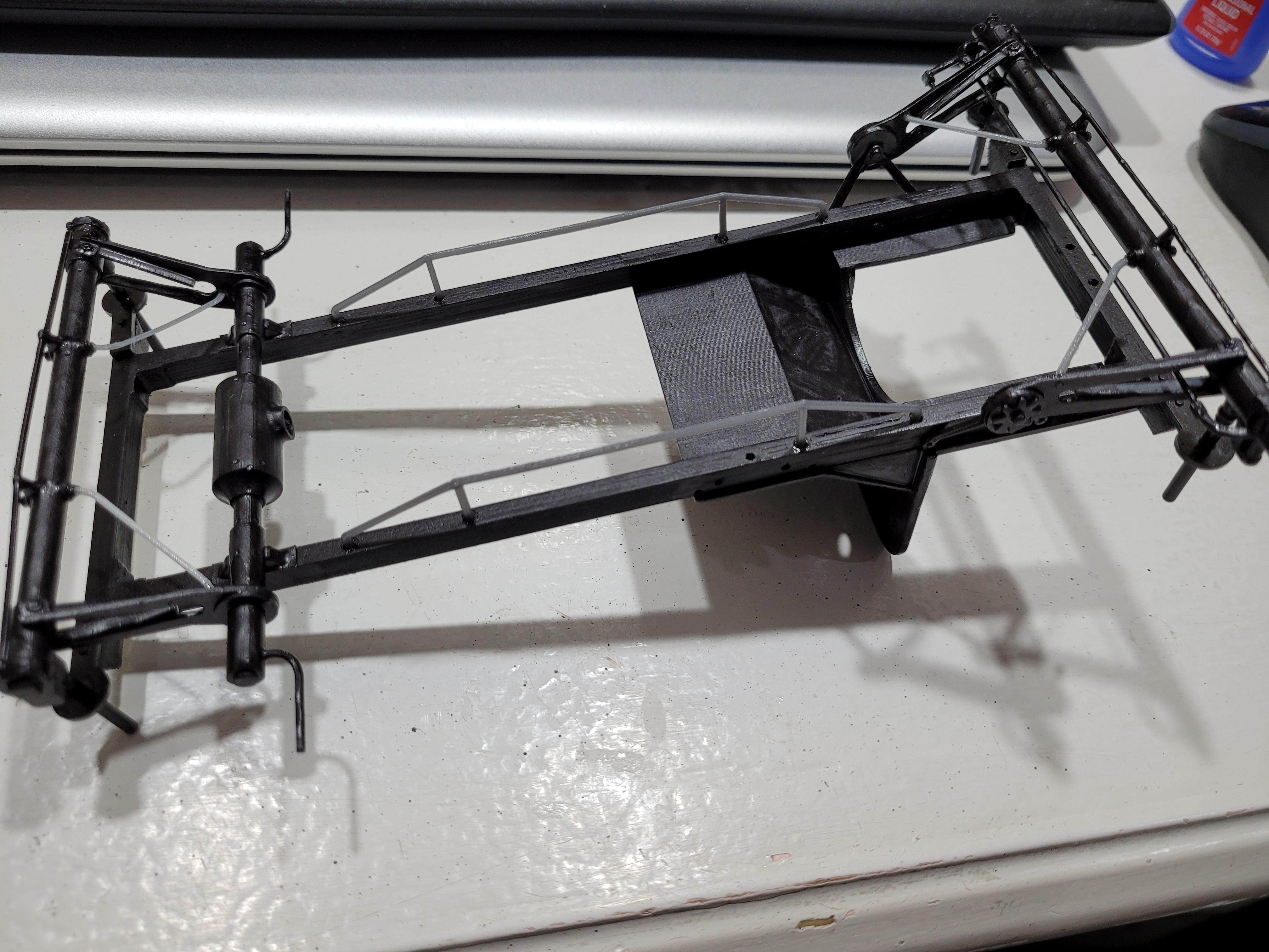
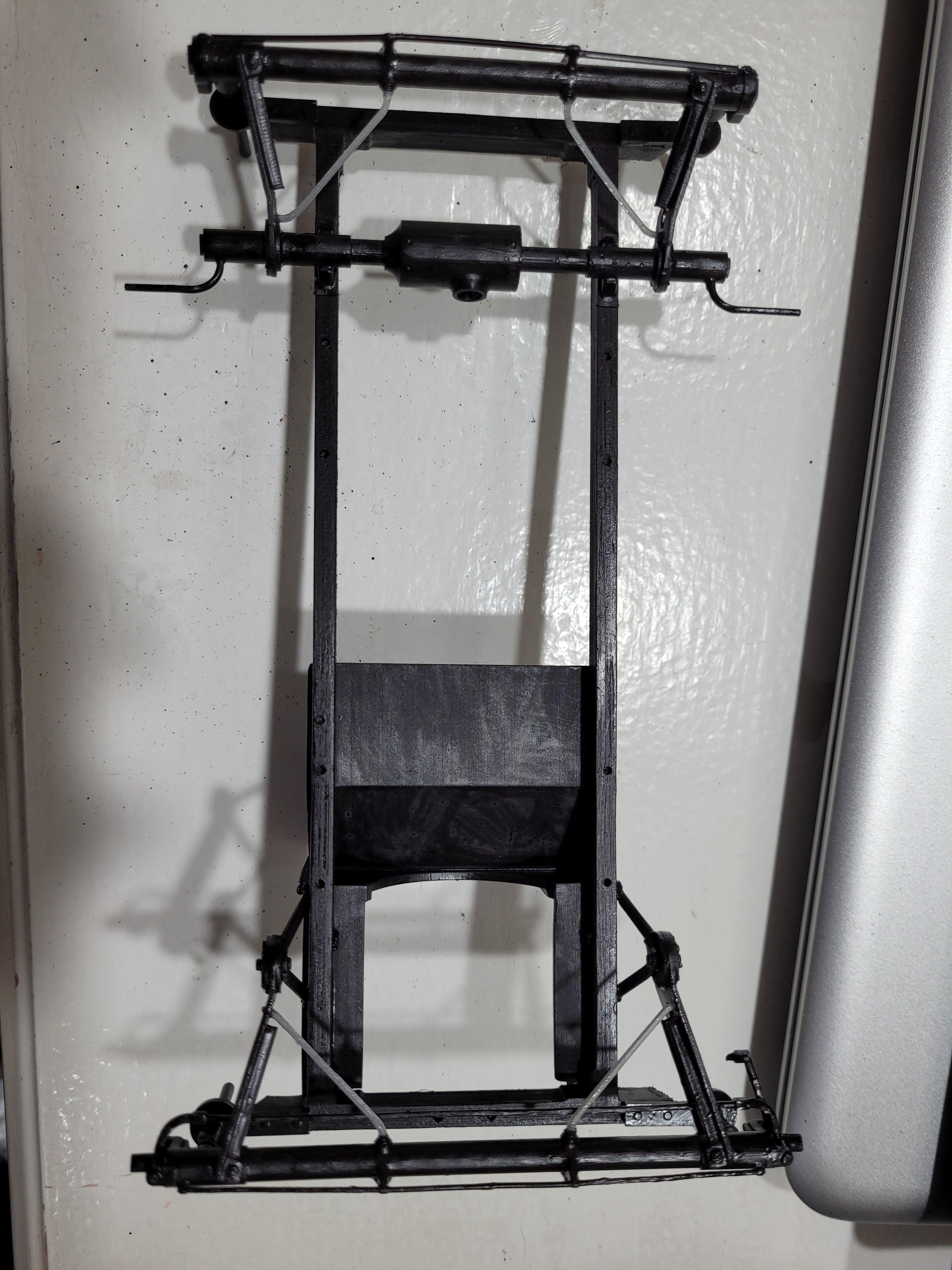
These ladder-looking parts were designed to stiffen the wooden frame.
-
The 4 gray braces are designed to stabilize the axles from side to side movement.
-
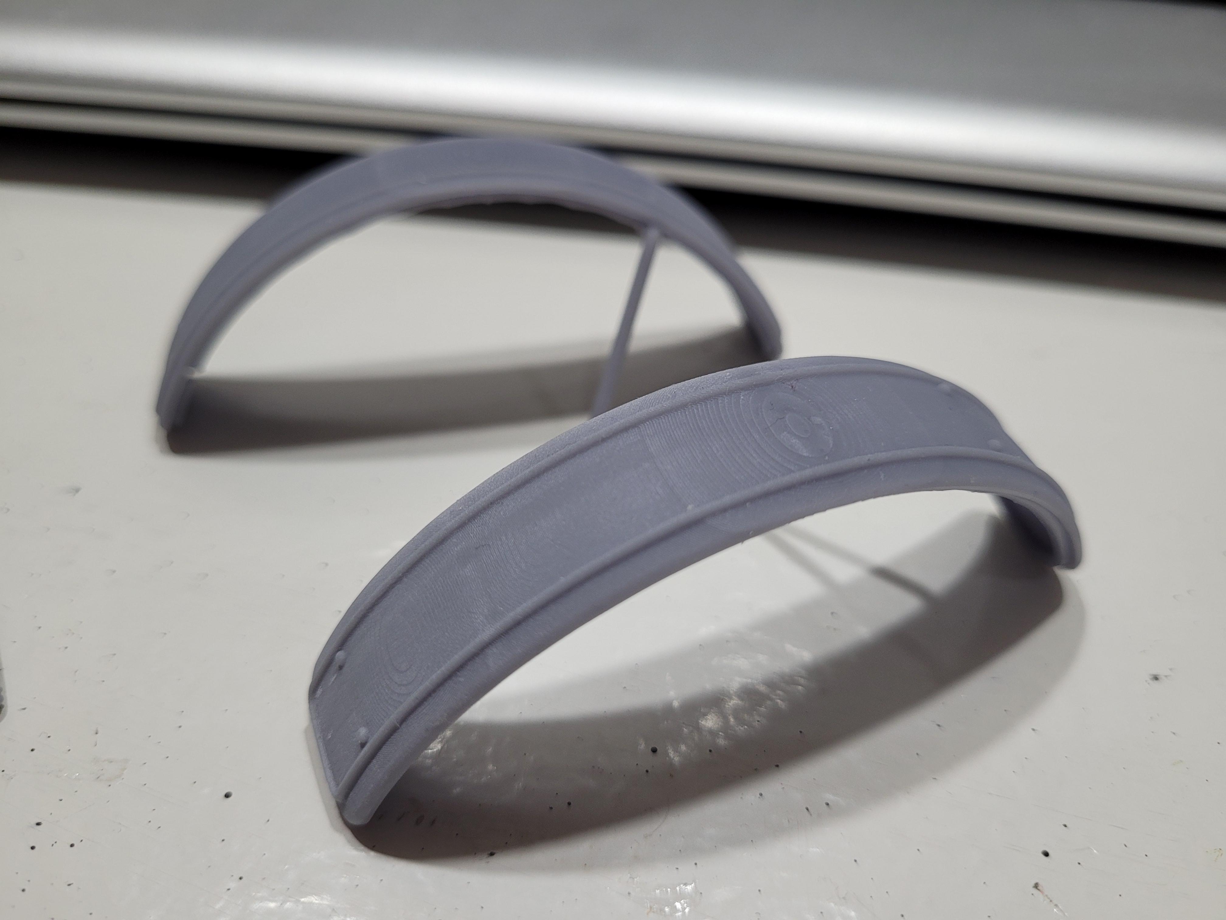
The rear fenders are printed.