kenlwest
-
Posts
277 -
Joined
-
Last visited
Content Type
Profiles
Forums
Events
Gallery
Everything posted by kenlwest
-
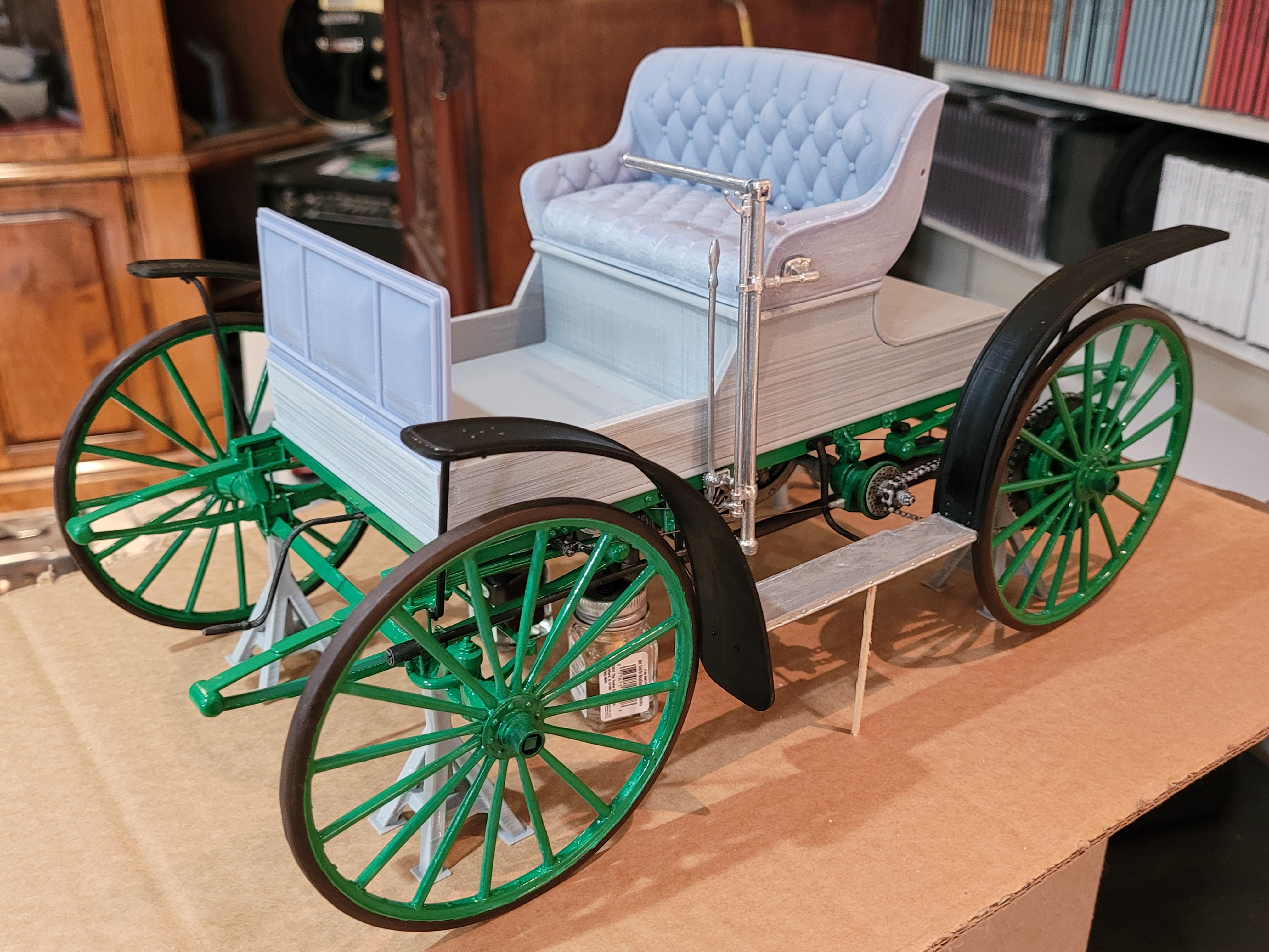
It's starting to take form.

-
Left side fenders and step.
-
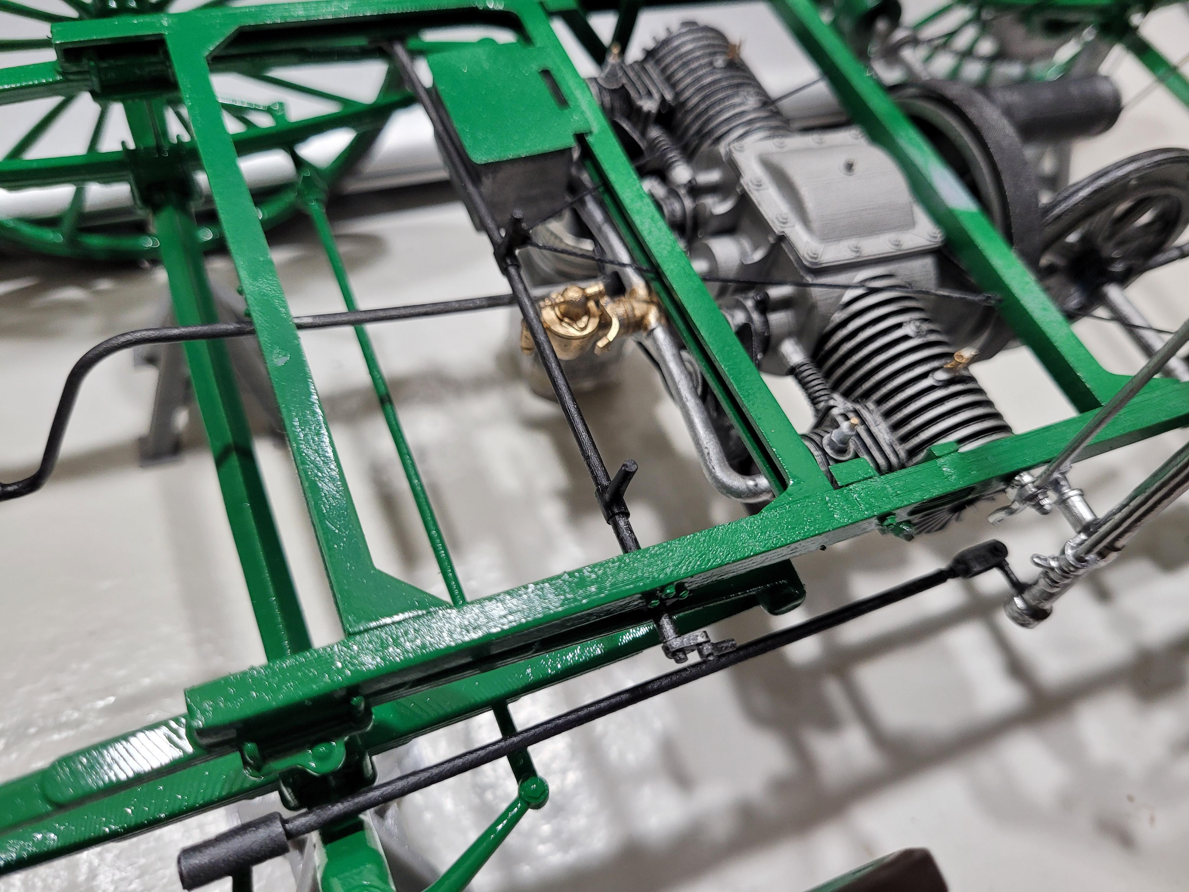
The speed control wheel disengagement rods are in place. These rods are pushed rearward by depressing the left pedal on the floorboard, thereby pushing the speed control wheel away from the flywheel (cutting power to the rear wheels).
-
May be hard to see, but the timing and throttle rods are in place. Please ignore the bad paint on top of the frame.. that will be covered by the body.
-
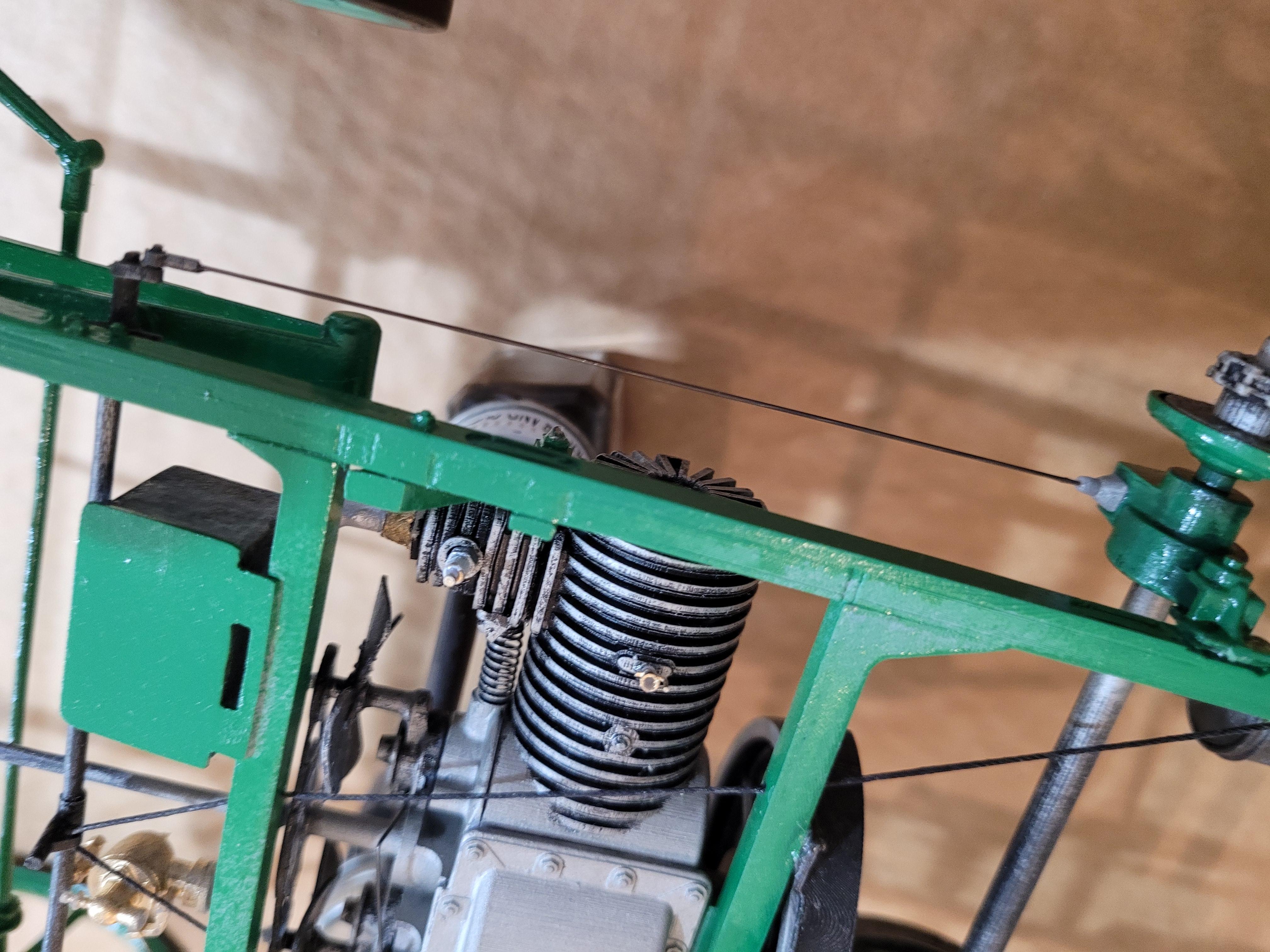
Drag link is in place. Also, if you look close, you can see the spark plugs, and the cylinder oil cups.
-
Control column and steering tiller.
-
Assembled the exhaust, brake cables, pedal bar, starter crank, and speed lever.
-
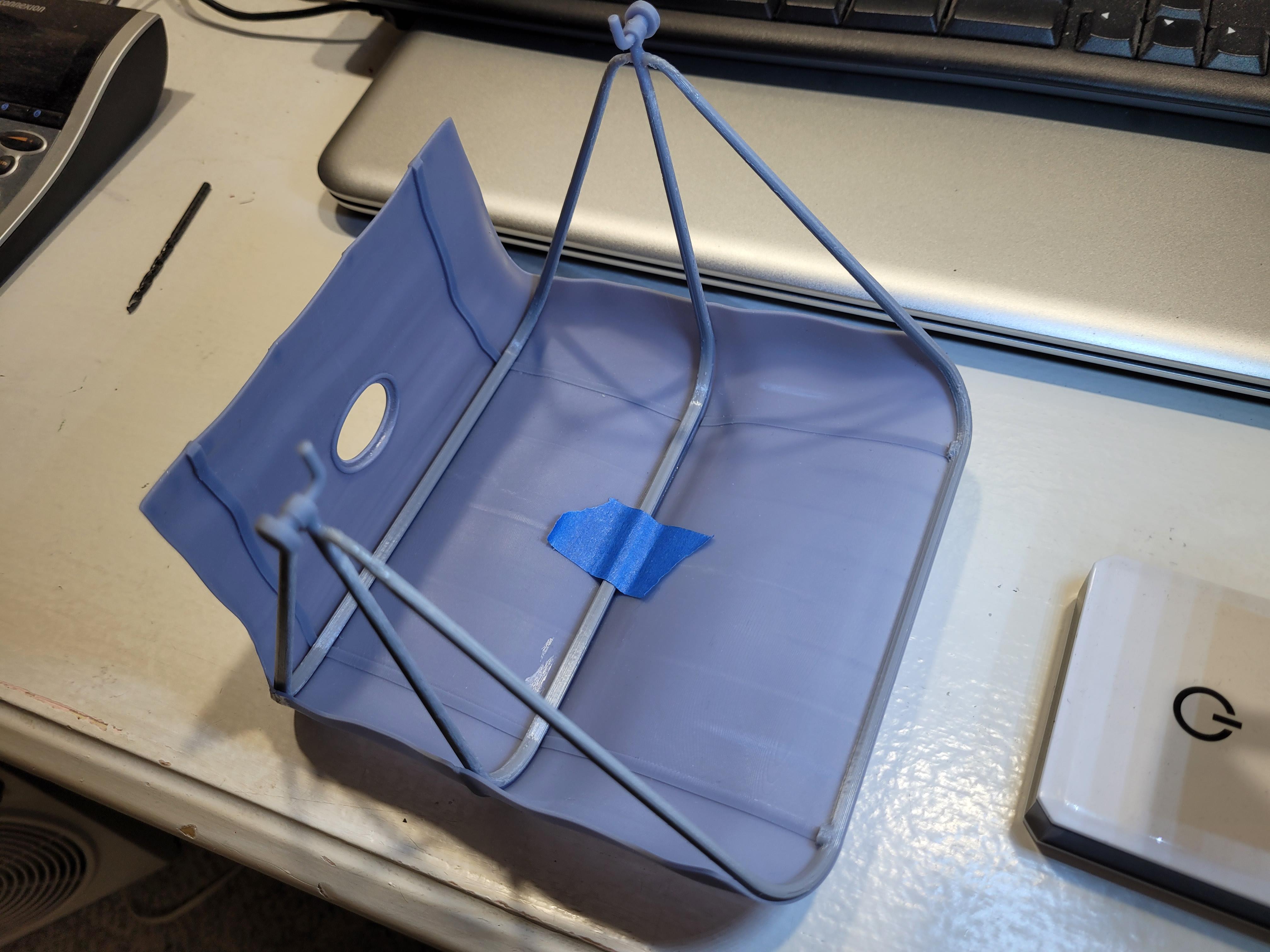
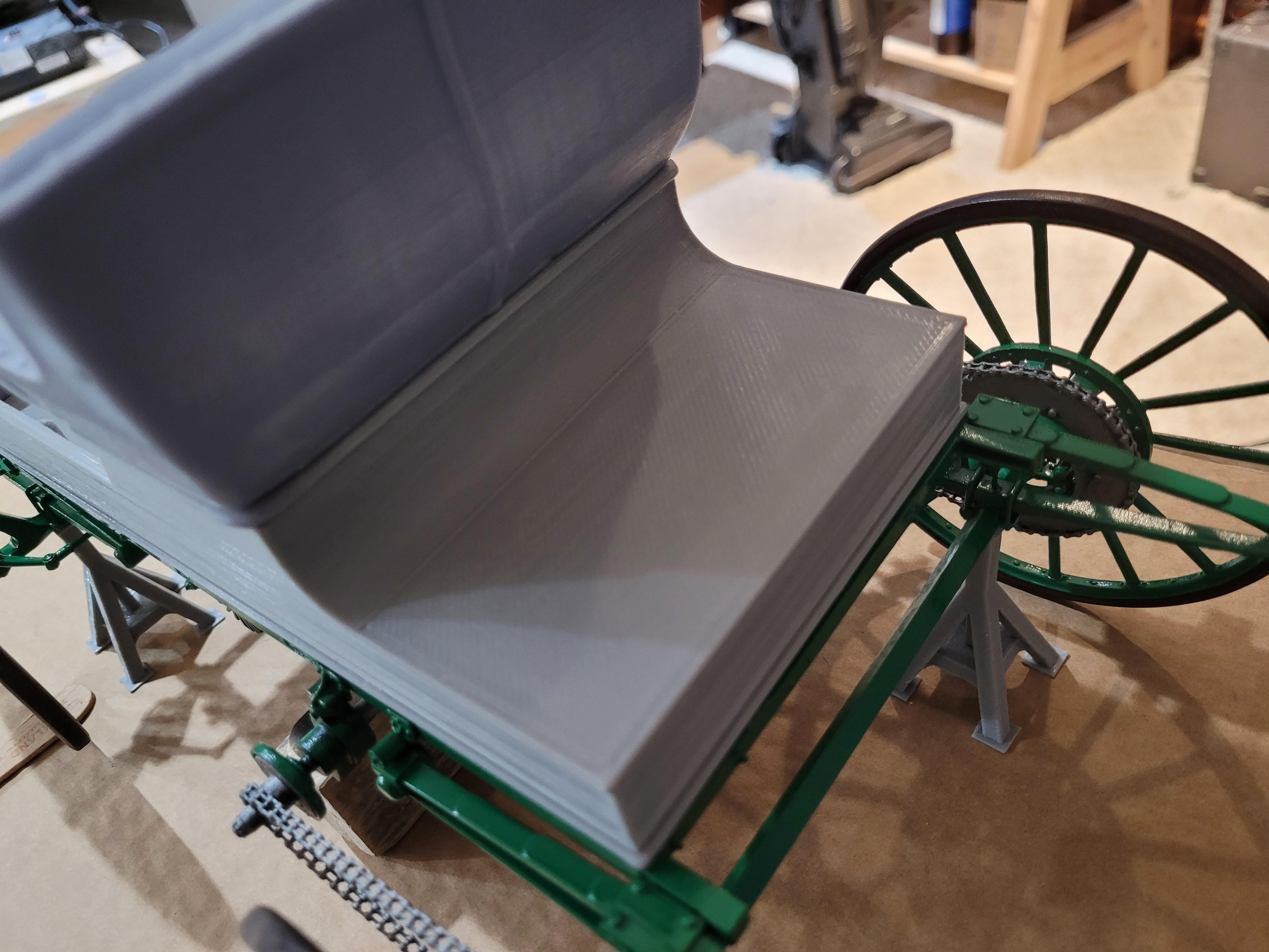
A quick check to see how to top fits the seat.
-
Using the top as a fixture to assemble the bows and hardware.
-
Here are the top hold down straps, with brackets and buckles.
-
Tonight I printed the top, (called an umbrella back in the day).
-
Parts to be finished and installed next; listed from top down: Speed control lever Tiller handle Pedal assembly Tiller column, throttle and ignition timing levers Umbrella hold down straps Clutch lever Starter crank handle Pedals Oil cups and spark plugs Steering rod Flywheel guard Ignition box
-
The exhaust system is assembled in 1 piece. A picture showing the rear deck lid in place. Also note that the seat rests on a thin wooden platform.
-
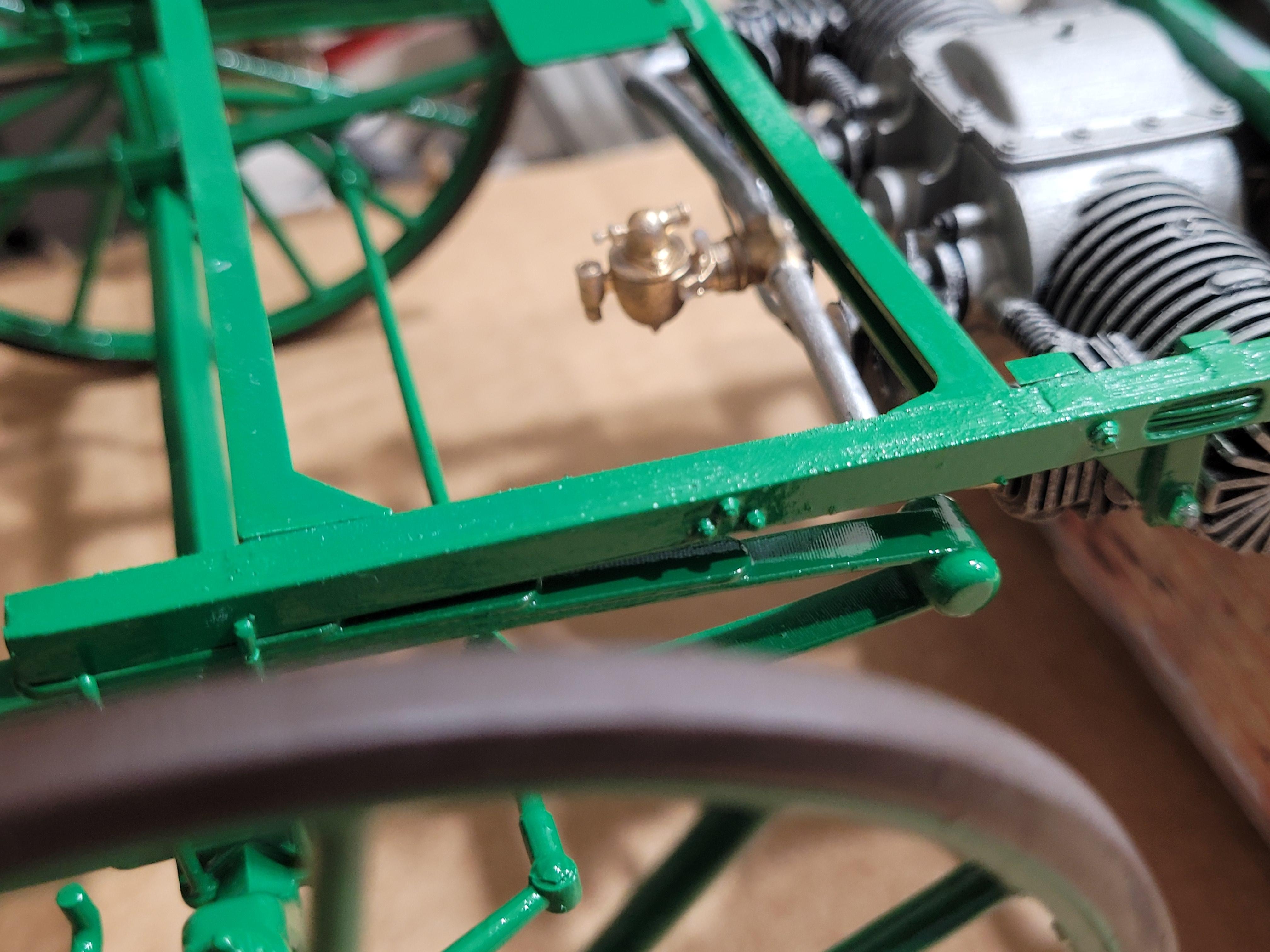
The carburetor in place.
-
The speed control lever. It moves the friction wheel across the face of the flywheel.
-
Rear chain sprocket with the brake shoes nested inside the drums.
-
Added the axle bearing hubs.
-
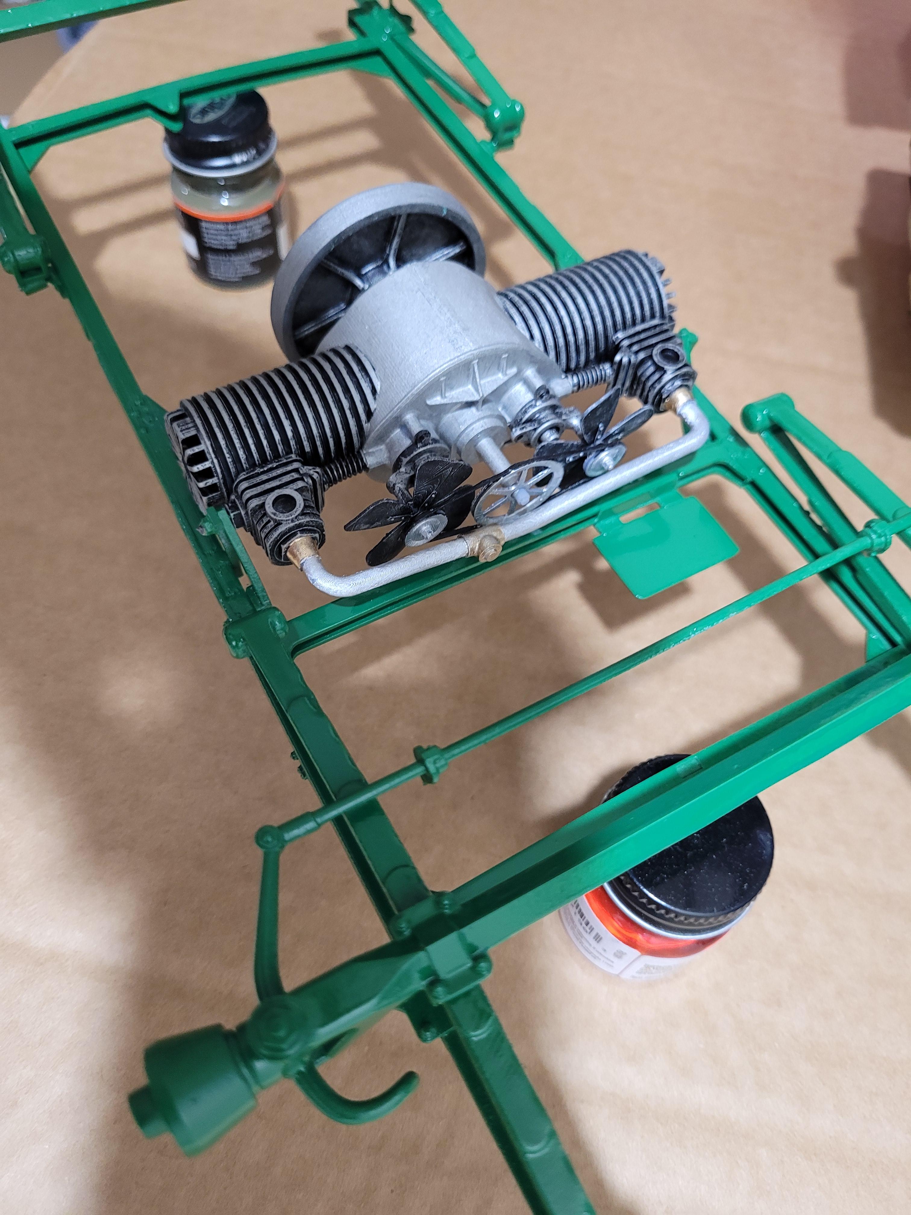
The chassis, minus control levers and cables. Also a preview of body and seat.
-
Here is a picture of the LH side differential housing. The housing dangles from a frame-mounted bracket, and swivels fore/aft, allowing the friction wheel to engage/disengage from the flywheel. Also note the castle nut at the end of the shaft.
-
The friction wheel can be moved away from the flywheel with one of the hand levers. I will show the detail on that in the coming days.
-
Exactly. Looking at the same reference picture, you will notice an "L" shaped lever directly behind the friction wheel. The lever is controlled by a vertical handle next to the seat. As the handle is pushed or pulled, the friction wheel moves side to side against the flywheel. The more outward the friction wheel moves, the faster the car goes. As the friction wheel moves toward the center of the flywheel, the car slows down. And, as the friction wheel crosses over the center of the flywheel, the car moves in reverse. The motor maintains a steady low rpm.
-
The term "dash" comes from the horse and buggy days. Dash has different meanings in the dictionary, but the one that is pertinate here is: "she was dashed with mud". The word "dash" was the name given to the shield that prevented dust, dirt, and horse exhaust and droppings from flinging up onto the passengers in the buggy. The term "dash" was carried over from the horse and buggy Era. Here is a picture of the dash for the Sears buggy.
-
Another point to make concerning CAD & 3D printing vs scratch using natural materials: the work I have seen in this forum using brass, soldering, wood and many other things, is impressive. Based on the accuracy of this work, I can see that it requires magnification, patience, and alot of fitting, trial and error, and time. In the end, I believe scratch building would be considered superior from a structural perspective, and creates a model that more reflects what the original subject was built from. Time is another important factor. The car I am building will take approximately 2 months from start to finish. That would need to be translated into hours in order to compare the time required to build the same car using traditional methods. I would be interested to know estimates of required time by those with experience in scratch building.
-
The drive gears, brake drums and wheel attachments, temporarily placed over the brake shoes. Also a picture of the drive wheel, to be installed later. This wheel serves as a clutch, and is the main component that controls vehicle speed. I will explain this in more detail when the rest of the system is in place.
-
The Sears MB was available in 3 color configurations: Chassis and Wheels were either - Brewster Green, Black, or Carmine Red. All bodies were Black. My version will be Brewster Green. The motor is attached to the frame with 2 pins; one on each side. The center frame bracket is attached to the back of the engine.