Ian McLaren Posted May 28, 2023 Share Posted May 28, 2023 (edited) That looks pretty good to me as is, if I was to change anything I would wrap the cowl panel just a tiny bit more around the windscreen with a slightly sharper point, but that is really nit picking. Edited May 30, 2023 by Ian McLaren Quote Link to comment Share on other sites More sharing options...
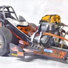
Straightliner59 Posted May 29, 2023 Author Share Posted May 29, 2023 16 hours ago, Ian McLaren said: I would wrap the cowl panel just a tiny bit more around the windscreen with a slightly sharper point, but that is really not picking. Thank you, Ian. As you are about to see, I wholly agree with you, regarding the cowl! Here's the updated scheme. It's subject to small changes, but, I am pretty happy with this. The electronics box is done! As always, comments, questions and critiques are welcomed. Thanks for looking! Quote Link to comment Share on other sites More sharing options...
Tortuga Kustomz Posted May 29, 2023 Share Posted May 29, 2023 On 5/3/2023 at 2:29 AM, Straightliner59 said: Thanks, Andy! Good luck in Salt Lake! Have a great time. I got the rear plate fabricated and attached to the transformer. I think I am down to four pieces to add, now. Then, I'll have to figure out where/how to mount it. I'm leaning toward bolting it to the water outlet, alongside the mag. It's not perfect, but it looks the part (no pun intended).Comments, questions and critiques are always welcome. Thanks for looking! Amazing detail, love how you build this, i need to try to do something like this 1 Quote Link to comment Share on other sites More sharing options...
Straightliner59 Posted May 29, 2023 Author Share Posted May 29, 2023 2 hours ago, Tortuga Kustomz said: Amazing detail, love how you build this, i need to try to do something like this Thanks, Marcos. It's a lot of fun, for me. A lot of it comes from just wanting to see if I can. From there, it's just acquiring enough information (photos, etc.), then, breaking an assembly down into its basic shapes. Then, it's relatively simple to build something that has the proper contours. Often, I have to rebuild a component, just because I didn't make it small enough, the first time!😅 You can do it, for sure, my friend! 1 Quote Link to comment Share on other sites More sharing options...
Tortuga Kustomz Posted May 30, 2023 Share Posted May 30, 2023 Thanks man, yes definitely i can try to do stuff like that, especially performance parts hard to find in the scale i work, but i'll try the way you do it looks a lot more simple then my way LOL 1 Quote Link to comment Share on other sites More sharing options...
Straightliner59 Posted May 30, 2023 Author Share Posted May 30, 2023 When I discovered that I was going to need a hole in the rear surface of the bellhousing for the shielded cable for the clutch sensor, and no room for a drill, I had to determine a way to get one there. My first thought was a straight pin, bent to 90 degrees and heated up, just like the olden days!😅 It soon dawned on me that it wasn't likely I'd be able to maintain heat long enough to actually make hole. Then, the light went on! A short section of the point straight pin, held in the tips of the resistance soldering unit's tweezers. I cut a pin and experimented with wattage settings on a piece of Plastruct rectangular tubing. Once I was satisfied the temperature was correct (enough), I positioned the point of the pin (now grasped in the tweezers), and hit the switch with my foot. Whew! No slippage. One hole, just where I needed it! It can be seen, here. I used .015" lead wire for fly-tying for the shield. The red wire in these shots is for effect, only. The actual clutch sensor wire, while red, is attached to the E-box. I need to open up a couple of the holes in the motor plate, to allow more wiring through--it's not as much as you might think, but, what's there won't fit the wires that need to penetrate it. Thanks for looking! 3 Quote Link to comment Share on other sites More sharing options...
Ian McLaren Posted May 30, 2023 Share Posted May 30, 2023 Looking great, nice outside the box thinking on the bellhousing, the new scheme looks very good! Quote Link to comment Share on other sites More sharing options...
Straightliner59 Posted May 31, 2023 Author Share Posted May 31, 2023 15 hours ago, Ian McLaren said: Looking great, nice outside the box thinking on the bellhousing, the new scheme looks very good! Thanks, kindly, my friend! It's funny, I hadn't "drilled" a hole with a hot straight pin, in probably 50 years! I'm looking forward to having the masks made. I started messing around with them, in AutoCAD. I need to drill the rear axle for the speed sensors, then I can install the E-box, and start running some of the wires. Quote Link to comment Share on other sites More sharing options...
Straightliner59 Posted June 1, 2023 Author Share Posted June 1, 2023 Since the next part of this project will require tying down a lot of wires, I figured I would want a variety of items to do the securing. I cut some (roughly) .030" strips of aluminum duct tape that I primered and painted semi-gloss black. This will represent 3/4" black electrical tape. I'm opting for the metal, because it will hold shape, as I doubt other materials would. I will also be using clear monofilament fishing line and .011" Clover House black nylon monofilament, to create translucent and black zip ties. I made a small tool from a dowel and a sewing needle, to pierce the "head" end of the zip ties. Also shown are the other items I'll be using, including an alcohol lamp, tweezers, and a plastic lid I use to dab super glue. I used the pencil sharpener to taper the dowel. It may be a couple of days, but I'll outline the process, as it happens. I have run a couple of cables: those for the hi-lo idle control, and the manual hi-speed (leanout). I'll get them "posed" once they're anchored to that tab. I'll run and tie down the shaft sensor, first, then get the controls anchored, then install the E-box. Questions and comments are always appreciated. Thanks for looking! 3 Quote Link to comment Share on other sites More sharing options...
absmiami Posted June 2, 2023 Share Posted June 2, 2023 Yup Quote Link to comment Share on other sites More sharing options...
Tortuga Kustomz Posted June 3, 2023 Share Posted June 3, 2023 really cool detail man Quote Link to comment Share on other sites More sharing options...
Straightliner59 Posted June 3, 2023 Author Share Posted June 3, 2023 6 hours ago, Tortuga Kustomz said: really cool detail man It should start to really fill out, in the next couple of weeks. Thanks, Marcos! Quote Link to comment Share on other sites More sharing options...
Straightliner59 Posted June 4, 2023 Author Share Posted June 4, 2023 Got started with the wire-tying-down process. So far I have only done the shaft speed sensor. I used "electrical tape" to secure those two wires. I made axle speed sensors from .032" brass tubing, and got them installed. I am rethinking my approach--I may install the dash panel, prior to the E-box. Still not 100% sure which way I'll proceed, there. In the meantime, here are some photos of things I've been working on, the past couple of days. Thanks for looking! 2 Quote Link to comment Share on other sites More sharing options...
Straightliner59 Posted June 4, 2023 Author Share Posted June 4, 2023 More electronics. I should have the dash mounted, pretty soon. I had to move the mag kill switch, as it interfered with the cross brace. I need to paint the "nuts" that mount the dash, and the terminals for the kill switch. Still work to do, but, we're makin' progress...Thanks for looking! 1 Quote Link to comment Share on other sites More sharing options...
Straightliner59 Posted June 5, 2023 Author Share Posted June 5, 2023 The dash is installed. I bundled the main harness with "electrical tape". I'll bind it to the chassis with zip-ties. The mag kill wires will be taped to the right side of the chassis, up to the motor plate. I am figuring out how to make the "T"-handles for the cables. I could easily do knobs, but I want the former. Questions, comments and critiques are, as always, welcome. Thanks for looking! 1 Quote Link to comment Share on other sites More sharing options...
Straightliner59 Posted June 6, 2023 Author Share Posted June 6, 2023 I did a whole bunch of housecleaning! "Tie-died" up the wiring. I used a combination of tape and zip-ties. I am very happy with the way it's turning out! I also got the control rods installed for the Manual hi-speed, and the hi-lo idle control valves. I still need to set up the one for the fuel shutoff. The kill switch it run through the motor plate, where it will meet up with the rest of the circuitry. Still work to do, but the crew really made some progress, today! I'll try to post the stuff about how I did the zip-ties, but, I want to see if I can get a bit more done, before bed. Photos are at various stages of completion. The first three are the latest. The red objects on the back of the gauge panel are dust caps for unused data ports. Thanks for looking! 3 Quote Link to comment Share on other sites More sharing options...
absmiami Posted June 7, 2023 Share Posted June 7, 2023 those zip ties are cool Quote Link to comment Share on other sites More sharing options...
Straightliner59 Posted June 8, 2023 Author Share Posted June 8, 2023 10 hours ago, absmiami said: those zip ties are cool I took some photos, as I was doing them. I intend to post them, when I have the time to do it properly. Thanks! Quote Link to comment Share on other sites More sharing options...
Straightliner59 Posted June 9, 2023 Author Share Posted June 9, 2023 I have begun running, and tying down the cables from the E-box. The right side is done, except for pulling that line through the cockpit, and around the rear of the axle, to the sensor. That process will be the same, on the other side of the chassis. I got the cable and shaft installed for the fuel shutoff, as well. The next conundrum to figure out is the connection at the motor plate, between the main harness, and its counterpart that hooks into the E-box. I have an idea. We'll see... I am attaching photos, as well, of the process of making the zip-ties. It's pretty straightforward. I simply push a length of nylon monofilament toward a flame, until it melts, and forms a bead, at the end. Mash the bead (The mono can be totally cooled--that's fine!) in a set of smooth-jawed pliers. Poke a hole in the center of the flattened area using a straight pin, or a sewing needle. Now, just wrap a loop of the mono around the items you want to tie together, push the loose end of line through the newly-formed eye, at the opposite end, and pull the line taut. Hit the joint with some CA adhesive, then firmly push it together with fine-pointed tweezers. Trim the end, and you're done! Questions comments and critiques are welcomed. Thanks for looking! 1 Quote Link to comment Share on other sites More sharing options...
Straightliner59 Posted June 11, 2023 Author Share Posted June 11, 2023 Everything forward of the motor plate is tied down, with the exceptions being the connections that need to wait for the engine. It took 30 or 31 zip-ties, and probably about 20 hours of work to get it here, but, I am pretty happy with the way it turned out. Hoping to get a couple of the rear connections made, before bed. Your critiques, comments and questions are always welcomed. Thanks for looking! 1 Quote Link to comment Share on other sites More sharing options...
Tortuga Kustomz Posted June 12, 2023 Share Posted June 12, 2023 WOW i can't believe a miss all this extravaganza man, the level of detail is insane, jus t love it 1 Quote Link to comment Share on other sites More sharing options...
Straightliner59 Posted June 12, 2023 Author Share Posted June 12, 2023 2 hours ago, Tortuga Kustomz said: WOW i can't believe a miss all this extravaganza man, the level of detail is insane, jus t love it Thanks, Marcos! The details are only insane, because I am! 😅 1 Quote Link to comment Share on other sites More sharing options...
Straightliner59 Posted June 13, 2023 Author Share Posted June 13, 2023 I got two of the three T-handles for the fuel controls made. The third one didn't solder well, so, i will solder up a new one. The bases are .032" brass tube. The handles are brass shim stock that was cut, and sanded to shape, after soldering. They were then polished with 4-way polishing sticks. They'll be cut to length and mounted to the shafts protruding from the dash panel, once those have been cut to proper length. The handles were curved by pressing them into the appropriately-sized divot on the dapping block. That keeps them all the same radius. Here are a couple more shots of the chassis and wiring, too. All that's left with that is to make connectors, and hook up the axle speed sensors. I'm pretty stoked to have my T-handles! Quote Link to comment Share on other sites More sharing options...
Straightliner59 Posted June 15, 2023 Author Share Posted June 15, 2023 (edited) I got the T-handles finished and installed. I also started work on the engine; I painted the oil pan and the block. Block is Testors Buffing Aluminum Metalizer, pan is Krylon Original Chrome oversprayed with Model Master Semi-Gloss Clear spray.. I need to make the connections to the rear wheel speed sensors, and tie down those wires, yet, as well. Your questions, comments and/or critiques are always welcomed. Thanks for looking! Edited June 15, 2023 by Straightliner59 2 Quote Link to comment Share on other sites More sharing options...
Calb56 Posted June 15, 2023 Share Posted June 15, 2023 The details you're accomplishing are beyond amazing. Quote Link to comment Share on other sites More sharing options...
Recommended Posts
Join the conversation
You can post now and register later. If you have an account, sign in now to post with your account.
Note: Your post will require moderator approval before it will be visible.