vintagedragfan Posted March 20, 2012 Posted March 20, 2012 yea Joe, personally I like #3 & #4, it is looking awesome! headers look sweet!!! O been there done that on the headers kickin my butt thing,LOL they are allways worth the trouble!
Mooneyzs Posted March 21, 2012 Posted March 21, 2012 Joe.... This is looking Killer man. I have to agree with the others here that I am liking pics #3 & #4 too. You are doing one heck of a job on them and just as Bill mentioned they are worth all of the trouble. I have 30 hours in the headers I have done for my Funny Car.... so I totally know your labor pains going thru it. stick with it and when you get to the end result after many tries... you will realized all of that work was worth it. You are doing an outstanding job on this whole build and its looking great.
Prostreet Posted March 21, 2012 Author Posted March 21, 2012 Thx. for the feedback guys and the kind words. Was messing around for a couple min. tonight with the exhaust outlet, not much pipe there lol. I really wanted it to exit closer to the door but i think it will look fine here also, The picture of the front end shows where it will exit. I may try and make another set of lowers for the headers tommarrow to put the turbos back where they originally were. I like where there at now and they both turned out even side to side. The 1:1 picture of the front end is off a 57 promod to show exit location.
eviltwincustoms Posted March 21, 2012 Posted March 21, 2012 Looks good Joe, but it looks like your exhaust outlet is a little anemic. What size diameter tube is that you are using? Curious, are you going to get enough flex in that Resin Nose to bow it out to get the fender over the exhaust outlets?
Prostreet Posted March 21, 2012 Author Posted March 21, 2012 Looks good Joe, but it looks like your exhaust outlet is a little anemic. What size diameter tube is that you are using? Curious, are you going to get enough flex in that Resin Nose to bow it out to get the fender over the exhaust outlets? anemic? 7/32" .218Dia. 5.5mm , If i make it flush with the body i have just enough to get it off. If i go bigger on the exhaust when i make the flange i won't have room for the boltheads, i thought about ordering a set of the 3" turbos, the ones there are the 2-1/2" turbos. But i think the turbo size looks ok.
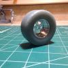
Kanedge Posted March 21, 2012 Posted March 21, 2012 Awesome build, just gone through looking at everything, this is going to be wild when finished. The wheels look amazing. Look forward to more.
Prostreet Posted March 22, 2012 Author Posted March 22, 2012 (edited) Thx. Guys, Ok the turbo's went back to the original location and are done. Every thing is just pinned together at this point, The exhaust exit is just for checking to see what it looked that's why they are unequal length but that is where they will exit. I still have to make the wastegates which i will attempt to do on my lathe, I will start on the intake tommarrow. This is what i want to build for an intake, but the throttle bodies will be in the back. Edited March 22, 2012 by Prostreet
tyrone Posted March 22, 2012 Posted March 22, 2012 YYEEEAAAHHH BOOOOOYY.... In my Flava Flav voice..... bada.. work Joe....
stump Posted March 22, 2012 Posted March 22, 2012 Joe, this build is entering epic status mate.....Looks FANTASTIC so far. And I'm another voting for your final exhaust choice...that looks pretty darn kool in my book. Most excellent work mate.
Mooneyzs Posted March 22, 2012 Posted March 22, 2012 Fantastic work Joe.... I have to admit that I think I like the way you have them even more now. I really like how you have them exiting out of the chassis. It looks awesome.
Red rocket 10 Posted March 22, 2012 Posted March 22, 2012 Joe this is one bad A ride , continued success, I can't wait to see the finished product. Leonard
Prostreet Posted March 22, 2012 Author Posted March 22, 2012 Thx. Guys , so while sitting here having lunch and looking at my pictures I just realized I need to run my steering shaft, hope it clears the turbo, gonna bother me till I get home from work lol.
comp1839 Posted March 23, 2012 Posted March 23, 2012 looks like the setup you started with joe. i like this the best out of what you've tried. ahhh, who needs steering? hehe. it's highly over rated. can't wait to see this with the manifold and all the plumbing. should be AWESOME!!!!!!
Old Sprinter Posted March 23, 2012 Posted March 23, 2012 (edited) Joe, again this is a really cool looking build that just gets better. I'm with Dave on the steering thing; you guys just go straight anyway LOL. I think that's why they make knuckles so the shaft can go around anything. I'm sure you'll figure out a way. Ken Edited March 23, 2012 by Old Sprinter
Prostreet Posted March 24, 2012 Author Posted March 24, 2012 Thx. Fellas, Glad you are enjoying it. I made the fuel and oil cells and turned down some caps on the lathe, I couldn't find any measurements in 1:1 for them so i winged it from pictures. Let me know what you think, They still need some finishing.
Prostreet Posted March 25, 2012 Author Posted March 25, 2012 Need some opinions guys, This is the TDR rack sitting in the frame. To me it looks to big what do you guys think? I may try to make one on my lathe, if i do any ideas what i can use for the boots?
Nicolas Posted March 25, 2012 Posted March 25, 2012 i would say that the rack is either to much on the front or it is too large. in the mock up you show here, the connecting rods will have a really huge angle to catch the wheels.
Prostreet Posted March 25, 2012 Author Posted March 25, 2012 i would say that the rack is either to much on the front or it is too large. in the mock up you show here, the connecting rods will have a really huge angle to catch the wheels. It's just sitting there for size reference, It will be back a little and i still have to make the arms for the struts.
comp1839 Posted March 25, 2012 Posted March 25, 2012 joe, it all depends on what you are trying to achieve. are you looking for "correct" or just "look good"?
Prostreet Posted March 25, 2012 Author Posted March 25, 2012 joe, it all depends on what you are trying to achieve. are you looking for "correct" or just "look good"? Dave both, and as close to correct as i can .
comp1839 Posted March 25, 2012 Posted March 25, 2012 first, the pinion location is incorrect. it should be below the rack not on top. as far as being too wide. it depends on what style rack you want to duplicate. if you are doing a rack with the ball socket inner tie rod end (like a stock rack) it doesn't look to wide. remember the ball socket is inside the boot. if you are duplicating a rack that uses a clevis and a rod end. it is too wide. the clevis and rod end live outside the boot. the important thing to remember is, the pivot for either of these setups needs to be as close as possible to the same vertical plane as the lower a-arm pivots. as far as the rack being too far forward. it's tough to tell from the picture but, it looks reasonable. if it helds the steering arm off the strut is about 6" c. to c.. hope this helps. if you have any other questions......yell.
Prostreet Posted March 25, 2012 Author Posted March 25, 2012 For being to big i was refering to the dia. of the rack mostly. It's just stuck together so i can change the pinion to the bottom. i may just try to make one for the heck of it and see how it turns out.
comp1839 Posted March 25, 2012 Posted March 25, 2012 joe, this would be the rack i am talking about with the clevis ends. it's stiletto rack. this way you could make non-flexible boots.
jmpsebring Posted March 25, 2012 Posted March 25, 2012 Joe I did recieve the 3" turbos. Do you want their dimensions?
Recommended Posts
Create an account or sign in to comment
You need to be a member in order to leave a comment
Create an account
Sign up for a new account in our community. It's easy!
Register a new accountSign in
Already have an account? Sign in here.
Sign In Now