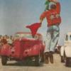
Bernard Kron Posted April 14, 2012 Share Posted April 14, 2012 (edited) I'm building this for a hot rod build-off on another board. They do a lot of show rods so a Flintstone 27 T body with Revell Parts Pack Caddy mill and mostly Revell 29 RPU suspension, a Lo-boy stance, Testors Inca Gold paint, pearl white frame and interior, and lotsa chrome seemed appropriate given my building style. The key influences for the image in my head are the Gary Heliker 26 T (which gained infamy in the movie Hot Rods To Hell), and the Ray Anderegg 25 T in the later “Golden Chariot” version recently cloned by Von Franco and featured as a TRJ cover car. The Gary Heliker T: The later Hot Rods To Hell Version: The Von Franco Golden Chariot clone as featured in The Rodder’s Journal: I've been wanting to do this project for a long time but have continually put it off because of the large amount of scratch building involved. But I think I may be up to it, now. I scratched together the chassis after having built the mill to get the dimensions I needed. The air cleaner is from Modelhaus. And here's a mockup for stance check, held together by rubber cement... The rear wheels are the ones I'll be using (from Modelhaus). The fronts will be chrome ones like the ones you see. The tires will be either these or slightly wider ones. Alternate tires and the chrome front wheels are on order from Modelhaus so that will probably be the long pole in the tent... Chopped Revell Deuce grill shell. I'm pretty sure I'll be running lakes pipes under the body to add some interest to the lower edge of the car. I'll probably have to make them. The really big challenge is now, and has always been, scratching together an interior. Probably no way to avoid it any longer... Thanx for lookin', B. Edited June 14, 2012 by Bernard Kron Quote Link to comment Share on other sites More sharing options...
Trans Am Erik Posted April 14, 2012 Share Posted April 14, 2012 Lookin great so far, got that stance just right. I like the Caddy air cleaner too. Quote Link to comment Share on other sites More sharing options...
Bartster Posted April 14, 2012 Share Posted April 14, 2012 I like the start. Good luck on the interior! "Hot Rods to Hell" is one of my favorite car movies! I'd like to build a 'T' soon. I'm watchin'. Quote Link to comment Share on other sites More sharing options...
rmvw guy Posted April 14, 2012 Share Posted April 14, 2012 I have'nt seen the movie but, after seeing these cool hot rods I want to. Very nice subject matter, I'll be waching. Quote Link to comment Share on other sites More sharing options...
1272148 Posted April 14, 2012 Share Posted April 14, 2012 (edited) I just love these classic movie / show cars they have a very interesting look about them Edited April 14, 2012 by 1272148 Quote Link to comment Share on other sites More sharing options...
southpier Posted April 14, 2012 Share Posted April 14, 2012 it's on youtube - lots of parts though http://www.youtube.com/watch?v=yAnWqWXd66M Quote Link to comment Share on other sites More sharing options...
crazyjim Posted April 14, 2012 Share Posted April 14, 2012 (edited) I think I'm going to like this build. How is a person supposed to find a part (like that air filter) on the Modelhaus site? Very confusing place to me. Edited April 14, 2012 by crazyjim Quote Link to comment Share on other sites More sharing options...
Bernard Kron Posted April 14, 2012 Author Share Posted April 14, 2012 Thanx guys! I do these mockups and stance checks at the beginning to make sure things look right and will go together properly. Looking at the car in photos and also "in the plastic", there was something that bothered me. It looked a little stretched out. I decided it was because the rear wheels were a little too far out at the corners, so I moved the rear axle in about 1/8 inch or roughly 3 1/8 scale inches. This tucks the top of the rear tire below the trunk line creating a symmetry between them, and makes the car slightly more close coupled without spoiling the Lo-Boy effect. Belows is a comparison between the two with new stance at the bottom. The camera angle isn't a perfect match but I think it shows the difference. I think I'm going to like this build. How is a person supposed to find a part (like that air filter) on the Modelhaus site? Very confusing place to me. Yeah, without any pictures the site is just a list of descriptions, with a ton of cool stuff tucked away in various categories. The Caddy air cleaner can be found on Page 1 under "Customizing Parts". It's available either plain or chrome plated. Quote Link to comment Share on other sites More sharing options...
Ramfins59 Posted April 15, 2012 Share Posted April 15, 2012 Replicas & Miniatures of MD also makes those Caddy air cleaners in resin... they're not chrome plated though. Quote Link to comment Share on other sites More sharing options...
race06 Posted April 15, 2012 Share Posted April 15, 2012 JUS spent 2hrs watchin videos n thought tow TRUCKS where cool BUT tow trains sumtin else!!! Quote Link to comment Share on other sites More sharing options...
Modlbldr Posted April 15, 2012 Share Posted April 15, 2012 Bernard- You made the right decision to move the rear axle forward. It makes the build look much better. The balance looks more correct now. Keep it up. I like the work on the frame. Later- Quote Link to comment Share on other sites More sharing options...
crazyjim Posted April 15, 2012 Share Posted April 15, 2012 I like the axle moved forward too. Quote Link to comment Share on other sites More sharing options...
James2 Posted April 15, 2012 Share Posted April 15, 2012 Another outstanding start, looks great so far. Quote Link to comment Share on other sites More sharing options...
Speedster Posted April 16, 2012 Share Posted April 16, 2012 Love the stance! Your frame is AWESOME! Quote Link to comment Share on other sites More sharing options...
Raul_Perez Posted April 16, 2012 Share Posted April 16, 2012 Looking good, Bernard! I'll add the 1/8" you took from this one to the '39 Ford Later, Quote Link to comment Share on other sites More sharing options...
Bernard Kron Posted April 17, 2012 Author Share Posted April 17, 2012 Thanx again guys! I’ve received several comments regarding the stance of this car and decided to revisit it one more time to dial things in to address what I thought were some perceptive and constructive observations. The result was that I did an extensive re-do of several areas. To begin with, I noticed that the rear axle interfered with the lower edge of the body, causing the body shell to be jacked up and spoiling the original channel I had done. Removing some additional bodywork to clear the rear axle corrected this problem. Next up was that I noticed that the front end was extremely low, creating a more extreme rake than I wanted and causing the front end to look more stretched out than was desirable. By lowering the suicide perch I raised the front end about 1/16” or about 1.5 scale inches. Lastly, the motor sat too high relative to the bodywork, a problem made even worse once I corrected the rear axle interference. I made several changes to address this, the goal being to place the upper edge of the oil pan at the same level as the tops of the frame rails.. First of all I changed the transmission from the very large automatic transmission that comes with the Parts Pack Cadillac to a compact little La Salle box which lowered the back end of the motor without having to rebuild the center crossmember. Next I fabricated new engine mounts that were slightly narrower and extended horizontally from the frame rails to support the engine at the center of the block casting rather than at the lower edge of the crankcase. With the engine lowered relative to the cowl top I found it necessary to raise the air cleaner slightly so I fabricated a small spacer placed between the air cleaner and the carburetor. With all these changes it was necessary to finalize the motor location in order to dial in the grill shell placement, a design element which is critical to determining if the front end would appear too stretched out. This required fabricating the firewall, which I made from an AMT ’29 Ford roadster unit. In addition I installed the motor’s chromed fan. And finally, because it effects where the eye is drawn in evaluating the overall stance, I mocked up a windshield frame resembling the unit on the Anderegg car. One more change still needs to be made. With the body properly located now, the grill shell will need to be cut down some more to align properly with the cowl. All this work really has made a big difference. The car sits more solidly on its wheels and looks more put together than it did. So , thanks to those who were interested enough to comment. Thanx for lookin’ B. Quote Link to comment Share on other sites More sharing options...
ronr Posted April 17, 2012 Share Posted April 17, 2012 You got now bud! Looking Good! Quote Link to comment Share on other sites More sharing options...
Raul_Perez Posted April 18, 2012 Share Posted April 18, 2012 I think that looks a lot better, Bernard!! Especially from the front 3/4 view. It still has some rake, but doesn't look like it's snow plowing it's way down the road. Later, Quote Link to comment Share on other sites More sharing options...
Dr. Cranky Posted April 18, 2012 Share Posted April 18, 2012 I like it a lot, Bernard. I'm looking forward to more progress. Quote Link to comment Share on other sites More sharing options...
deathskull59 Posted April 18, 2012 Share Posted April 18, 2012 cool hot rod and is that a resin body. Quote Link to comment Share on other sites More sharing options...
Bernard Kron Posted April 18, 2012 Author Share Posted April 18, 2012 (edited) Thanx everyone. ... is that a resin body. Yes, from Jimmy Flintstone. Edited April 18, 2012 by Bernard Kron Quote Link to comment Share on other sites More sharing options...
Bartster Posted April 18, 2012 Share Posted April 18, 2012 The stance is PERFECT!!! Might think about dropping the tranny a tiny bit? Looks tuff. Quote Link to comment Share on other sites More sharing options...
Bernard Kron Posted April 20, 2012 Author Share Posted April 20, 2012 (edited) I’ve made a small modification to the engine mounts so that the motor now sits with the valve covers parallel with the frame rails and the top of the oil pan just about even with the top of the frame. This update is Part One of the interior fabrication. One of the challenges one faces when working from a resin body for which there is no equivalent kit is that a large part of the build must be made from scratch. I find the process is often part logic and tactics and part accident and discovery. This is an excellent example of what I mean. To start with I made an interior structure by tracing a pattern directly from the inside surfaces of the body to paper. Then I copied the pattern to a sheet of .010” styrene and cut it out. This would form the base for the actual surfaces you would see. Here is the pattern displayed flat and then installed in the body. It’s held in place using rubber cement. Then I fabricated the “upholstered” surfaces using Evergreen Novelty sheet styrene in a siding pattern for the main surfaces and styrene half-round rod to make the bolster that will run around the outer edge of the body. The bolster was built up from .1875” stock and .080” stock glued together to form a “P” shape. The pieces were based on the original pattern I made and trial fit and trimmed using rubber cement before being permanently glued to the base using liquid cement. Here are the pieces that resulted. As you can see the base has broken apart from handling. The .010” styrene sheet becomes quite brittle and fractures and tears easily. However, I didn’t want to use anything thicker to minimize fitment issues. (The photo is out of sequence as will be explained below.) Once the upholstered surfaces were finalized and glued in place to the base I clamped them in place and left them for a time in order for the plastic to gain some memory and conform to the compound curves of the interior. That explains the curved ends in the photo above. I discovered that once the interior tore apart installation of the interior pieces became much easier with no sacrifice of accuracy of fit. And finally, here is the completed interior as it stands up to this point. You’ll note the small half-round .080” strips sticking out on the ends at the back. These will be bent home and glue in place to form a continuous strip and the seams and gaps filled and sanded to final shapes. Tactically this means the interior will have to be glued into the body before painting and the body masked and the interior painted but I can’t think of a way to avoid this. It should be obvious that my build style is pretty improvisational, with some advanced planning but a lot of “on the fly engineering”. I haven’t decided whether to make a bench seat or use buckets. The inspiration cars both have bench seats. I’ll probably try both before deciding. A floor needs to be fabricated and a dashboard made. About the only thing I’ve decided on in advance is to use a ’60 Chevy Impala steering wheel from Modelhaus which will influence my design decisions. Thanx for lookin’, B. Edited April 20, 2012 by Bernard Kron Quote Link to comment Share on other sites More sharing options...
Bartster Posted April 20, 2012 Share Posted April 20, 2012 Nice fabrication....scratch building....nice work. The interior is looking sharp so far. Quote Link to comment Share on other sites More sharing options...
Bernard Kron Posted April 25, 2012 Author Share Posted April 25, 2012 Thanx! This is a small update which actually represents a fair amount of work. The body is narrow enough that using bucket seats proved impractical. In order to build out a bench seat I needed to finalize the floor of the car, The floor, in turn, needed to take into account the transmission and drive train to the degree to which it intruded into the cab. In a car this small everything is tightly interrelated. The floor was fabricated from styrene sheet, rod, and strip with a low transmission tunnel which doubles as a support for the bench seat. The “upholstery” for the seat bottom was made from the same half round rod and siding patterned styrene sheet as the sides and back. Below is a composite picture showing the interior and floor from various angles. It’s all in raw plastic because I’m trying to avoid gluing and painting until everything is fabricated and fully test fitted. This might sound obvious but in the past I have tended to glue and paint as I went along, leading to more problems than was necessary if I had been disciplined enough to complete all my sub-assemblies before doing finish work and assembly. Next up will be the dashboard and windshield, which, once again, are interrelated. Once that’s done the interior will be complete and I can move on to finalizing the suspension bits and beginning paint and assembly. Thanx for lookin’, B. Quote Link to comment Share on other sites More sharing options...
Recommended Posts
Join the conversation
You can post now and register later. If you have an account, sign in now to post with your account.
Note: Your post will require moderator approval before it will be visible.