
Straightliner59
-
Posts
4,676 -
Joined
-
Last visited
Content Type
Profiles
Forums
Events
Gallery
Posts posted by Straightliner59
-
-
Thanks, Bernard! It was supposed to be finished before I left Minnesota, but...won't be long now. Thank you for the kind words. I appreciate them!
-
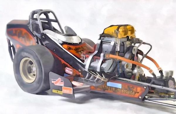
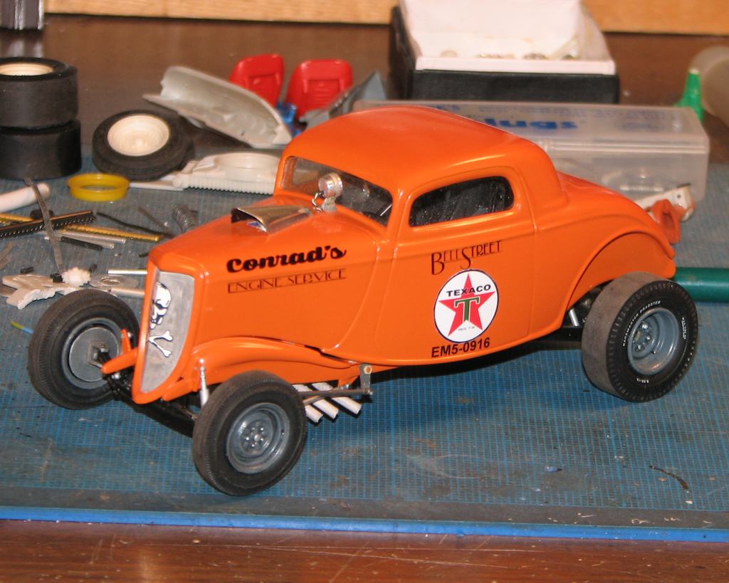
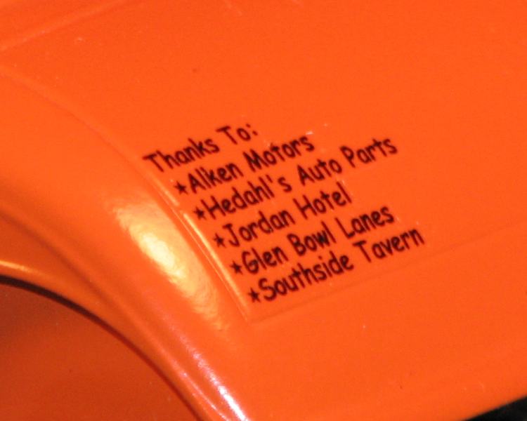
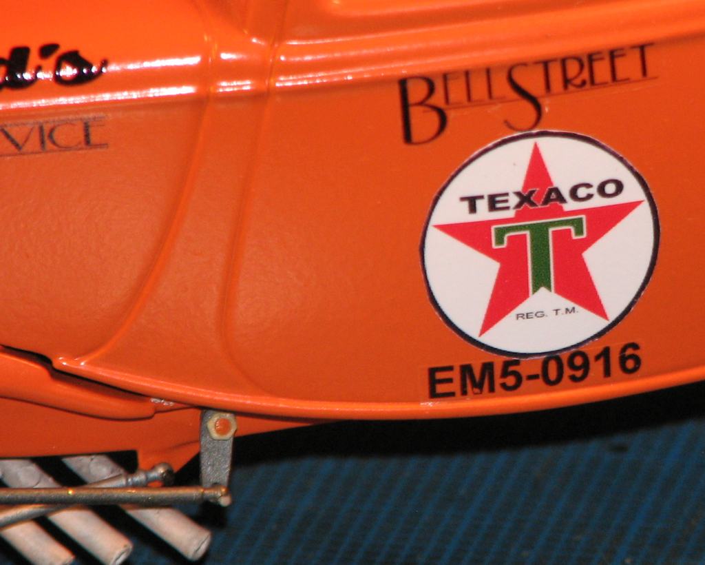
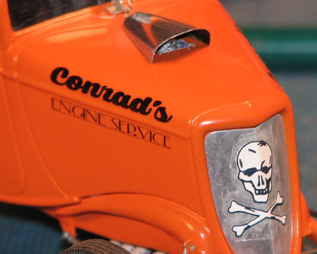
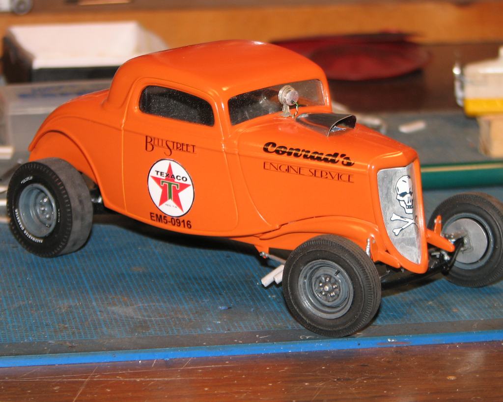
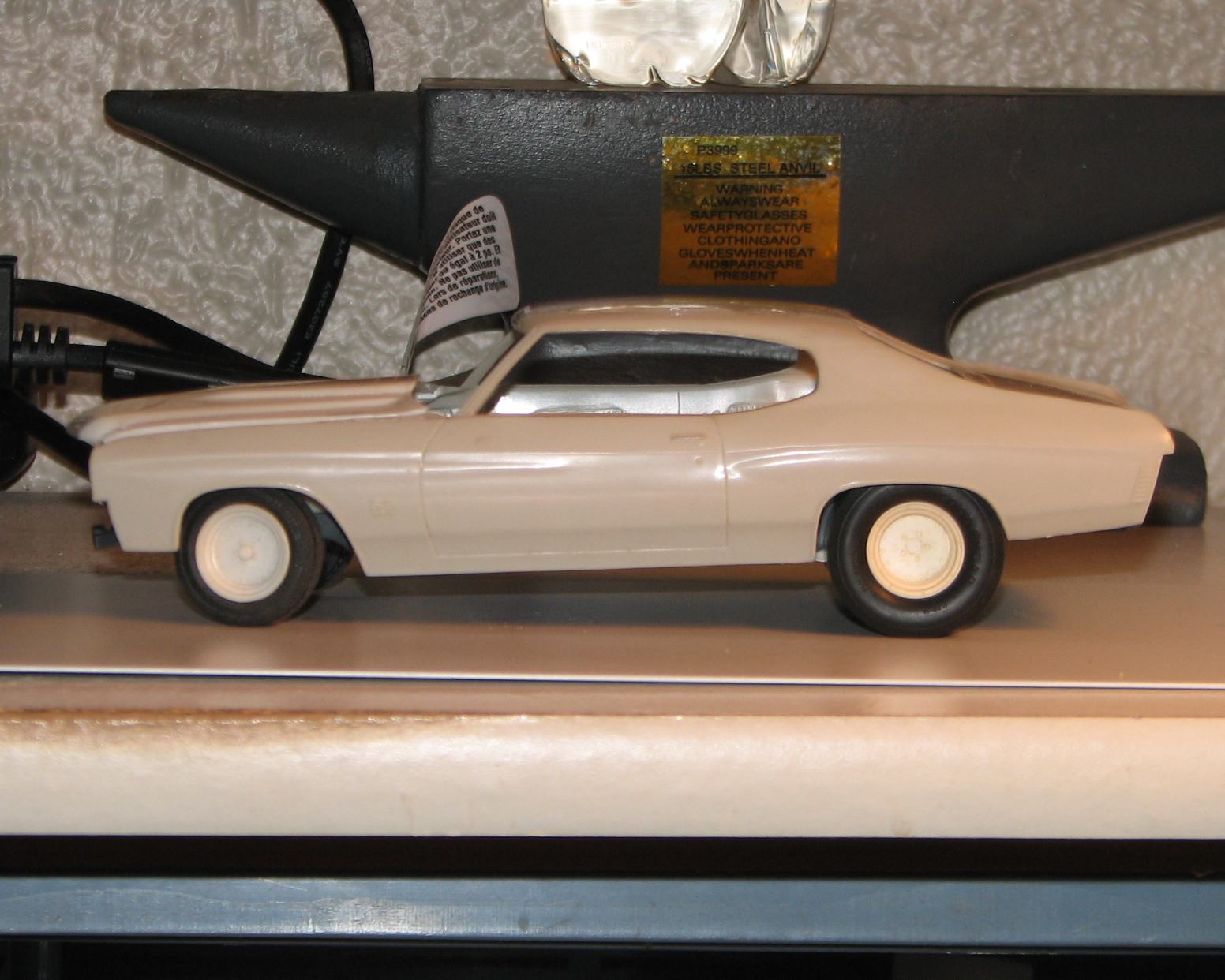
This project is nearing completion, as all I have left to add are a handful of small pieces, a couple of product logo decals (I'd call them contingency stickers, but, what would they have really been worth in 1960?), and some touch-up. She has her warts, but I like the way it sits. I made all these decals, except for the skull, which came from an aircraft sheet. I don't know if anybody else has used the inkjet sheets from Blinggasm, but I am very happy with the results. I got both clear and white, through Amazon. The clear is very thin, and went down without a problem. I "built" the Texaco logo from scratch, using PhotoImpact Pro, and printed it on white. I manipulated various fonts and added the lines with PI Pro, as well. Those were printed on clear.

-
Coming along nicely, JC! I've been hankering to build a road racer, and this is inspiring,
-
These should help with the sleeper mounts. Excellent work! Shame on you for making me want to work on a truck model! :-)
-
Thanks for the suggestion Daniel. Does the rod have a metal core? I have some metal core styrene rod IIRC was made by Evergreen.
Nope! Its formula allows it to be bent by hand, and retain its shape without applying heat. I remember the rod with the wire, but don't recall if it was Evergreen or Plastruct who made (makes) it. You want to use some finesse, in bending it, but, I love the way it behaves.
-
Any tips on bending plastic rod JC?
There's a place in England that sells bendable styrene rod. In the U.S., Midwest used to market it as "Super Styrene". Alas, it is no longer available here, as far as my research has led me. I ended up buying it here:
http://www.cornwallmodelboats.co.uk/acatalog/raboesch-styrene-profiles-1000mm.html
You can bend this by hand. It works great for headers, roll bars, sway bars, etc. I used it to make the sway bar for my Malibu. I've used it in other applications, too, and I love it so much I actually ordered some from the U.K., when I began to run low.
-
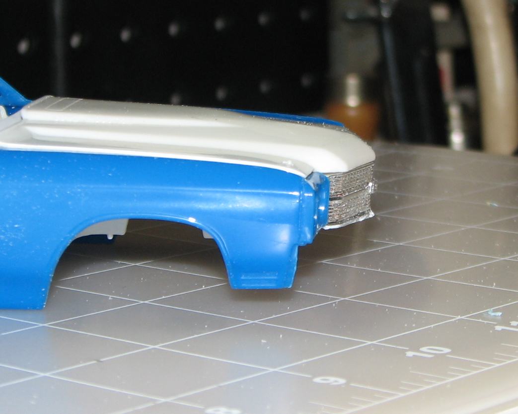
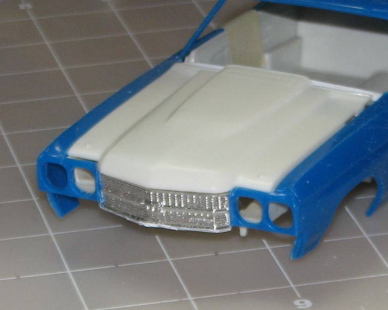
While you're fiddlin with the hood, you may want to re-sculpt the cowl induction scoop, either with putty, or by cutting it out and splicing in the AMT piece - Revell under-sized it, AMT is much closer to correct. I'll get a pic up as soon as I can, showing measurements on an actual hood. That, the soft detail and "rounding" of the grille, and the four mystery objects molded to the sides of the console are the only real problems I see with the Revell kit, and none are too difficult to overcome. Is that chassis not a beaut for a snapper?!
My so far ever-evolving plan is to use the AMT grille, which is shown, attached below. I've only just cut it out of the rest of the part, and sanded it, to fit. I am leaning toward using the entire AMT hood, sectioned crosswise somewhere behind the headlights and the front of the scoop, and adding a (roughly .125") strip from the same area of the snapper. Of course, I hadn't noticed the "roundness" of the grille, until you mentioned it. As soon as I looked at it, I knew what you meant, so thanks again for your commentary. The engraving on that chassis is pure art!
-
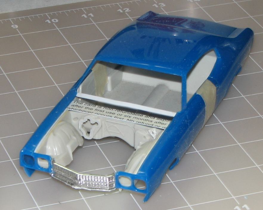
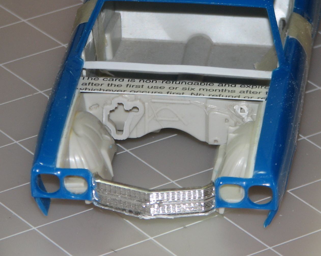
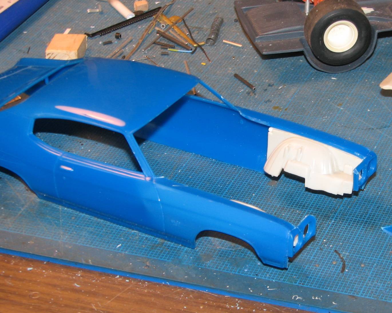
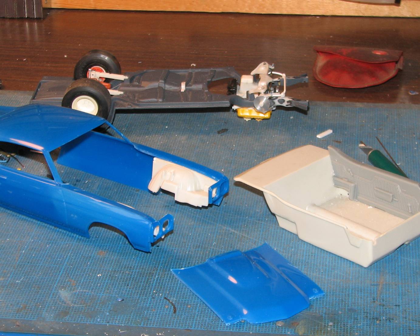
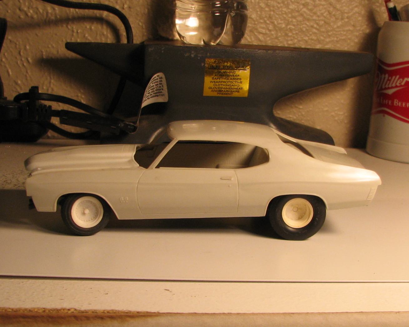
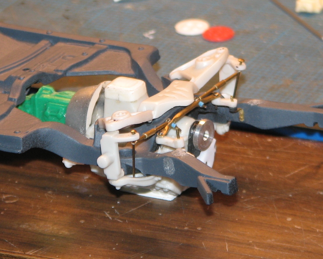
Update: I got the hood cut out of the SnapTite body, and installed the inner fender wells. Rear shocks are built from aluminum tubing. The "eyes" are glued to the shocks with JB Weld. There's a small amount of material that needs to be removed from the back seat area of the AMT tub, so that the Revell side panels will fit in the interior properly. Next up, I am going to begin working on the cowl/firewall assembly.
-
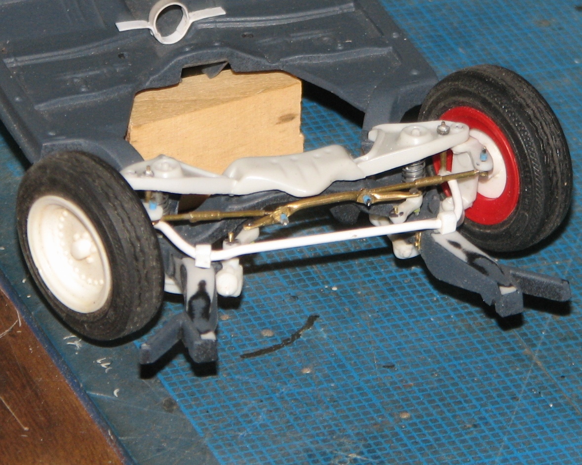
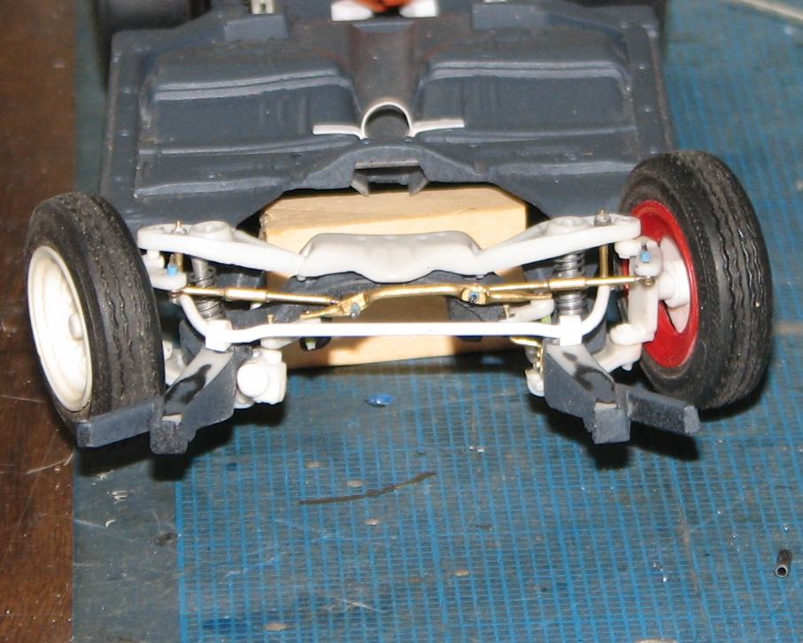
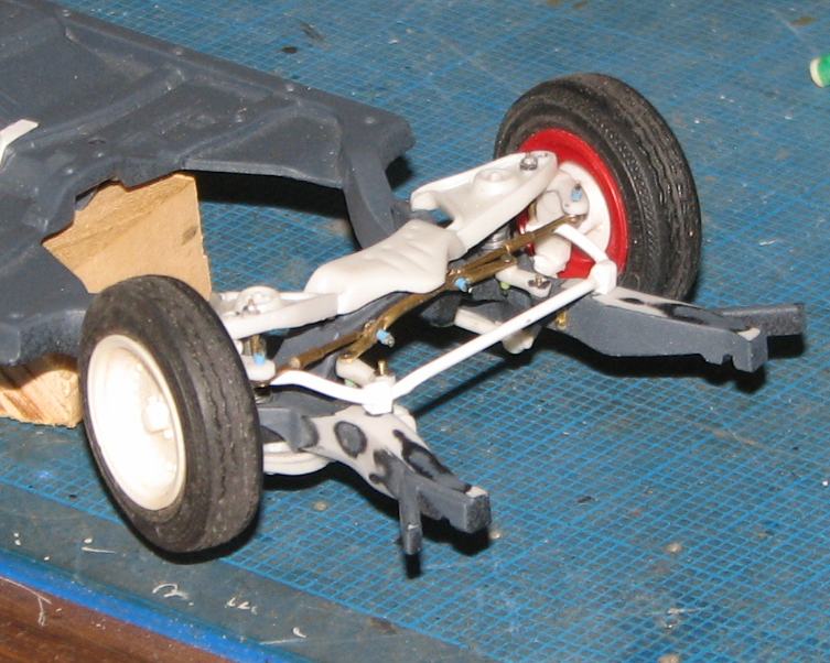
There's a surprising amount of difference in the rear wheelwells, the slicks sure do fit the snap body better. That's got to be the most detailed and accurate front suspension work I've seen on a Chevelle. Good work!
Thanks, Glenn! It's definitely the most effort I've ever put into a front suspension. Your words are much appreciated! That snap body is really nice. Wish they'd use it as the basis for a full detail kit!
-
Frisket material (still on its backing) doesn't seem to be sturdy enough to be feed through one of those cutting machines.
I have a friend who always used contact paper for masking when he was lettering race cars. I think that might work better than frisket paper, and it's a lot cheaper, too!
-
I'd like to thank Mr. Gribble...er, Shackleford for his input and interest in this project. Without it, I'd never have noticed/learned of the shortcomings of the AMT body.
-
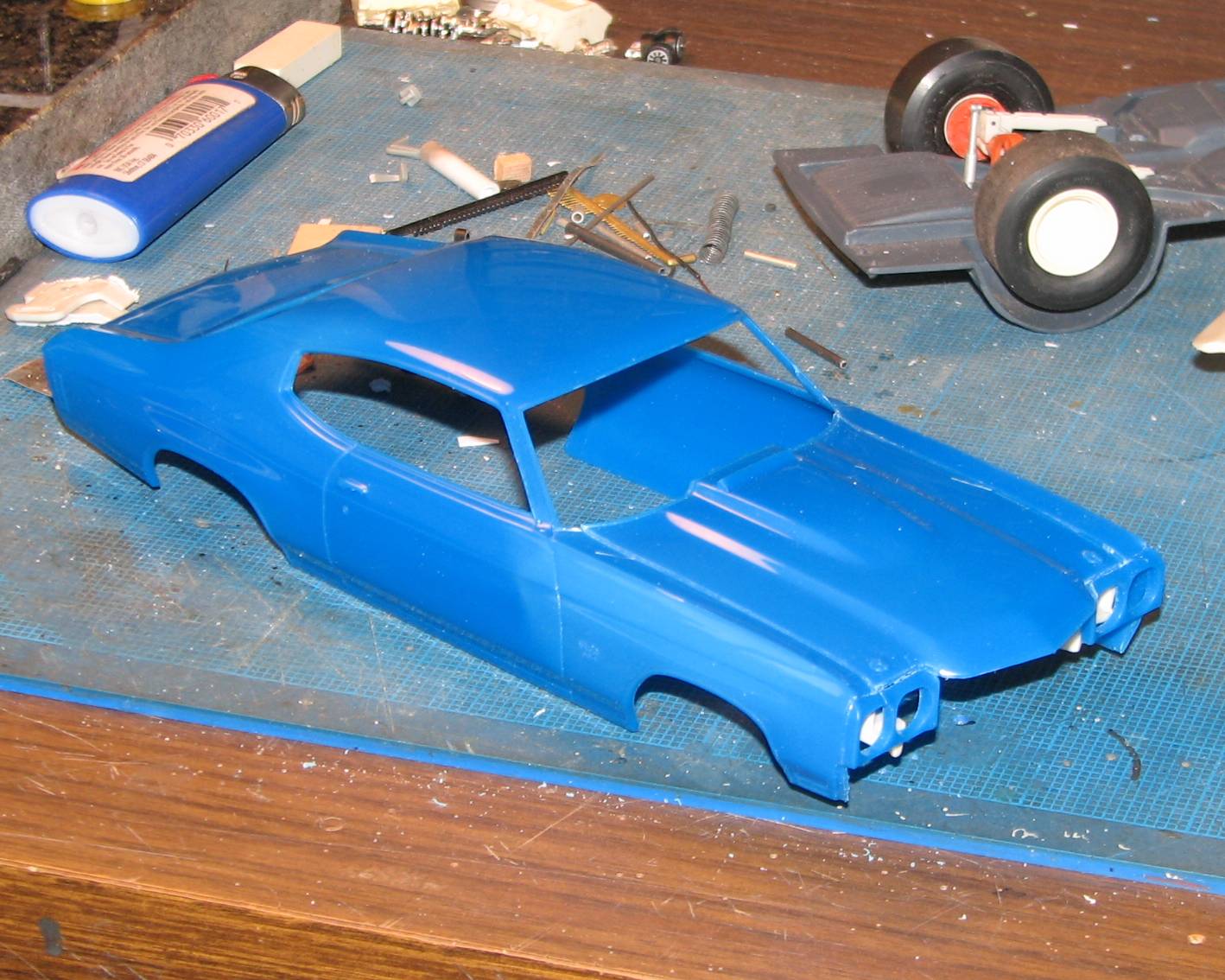
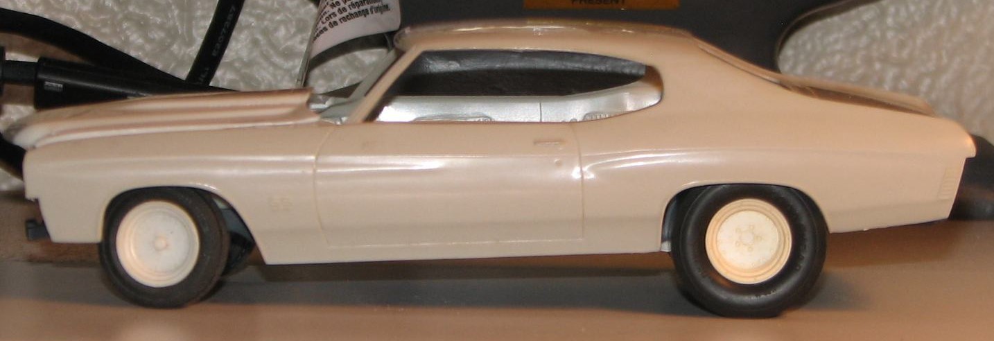
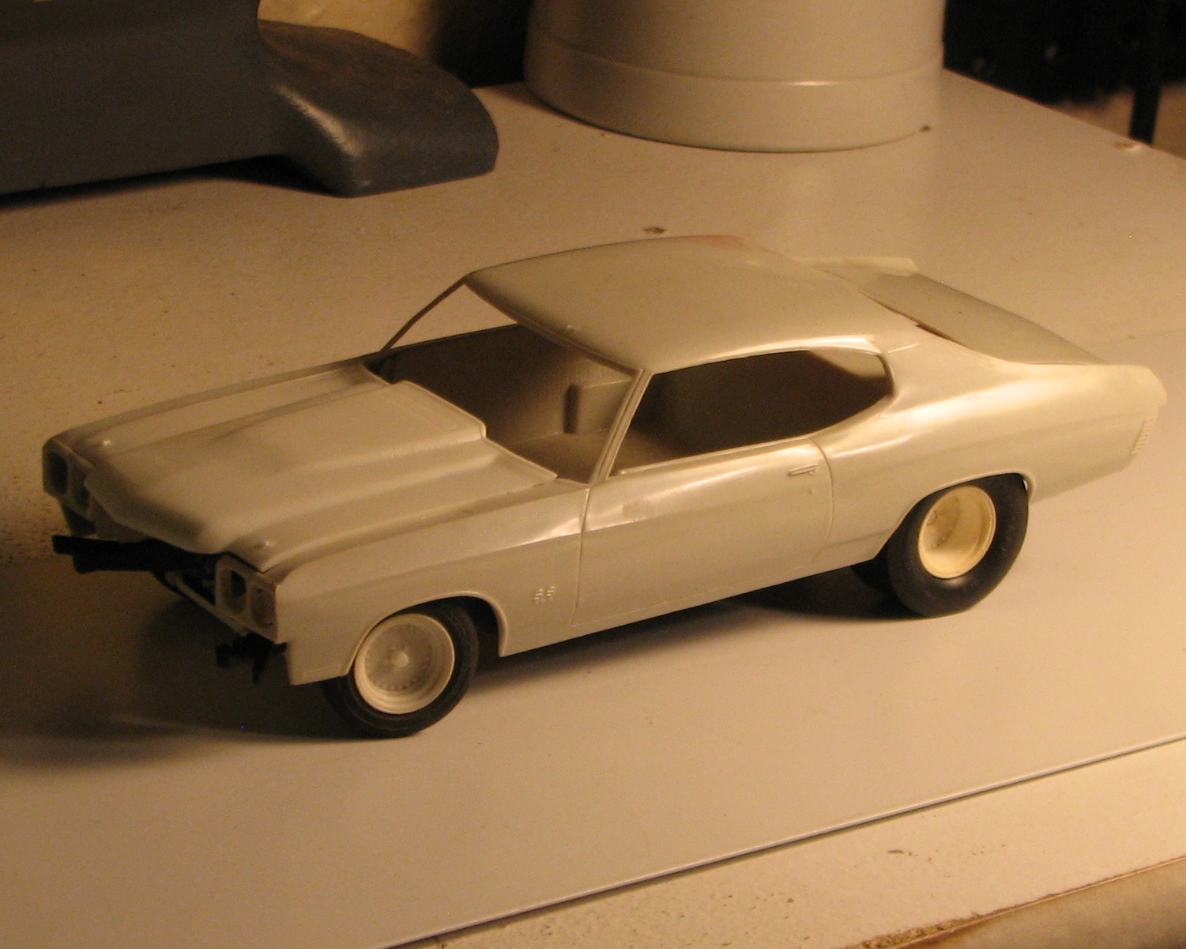
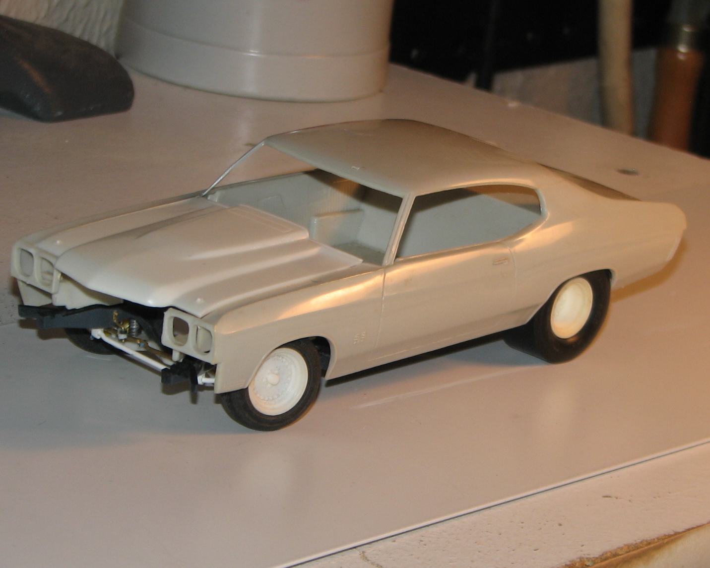
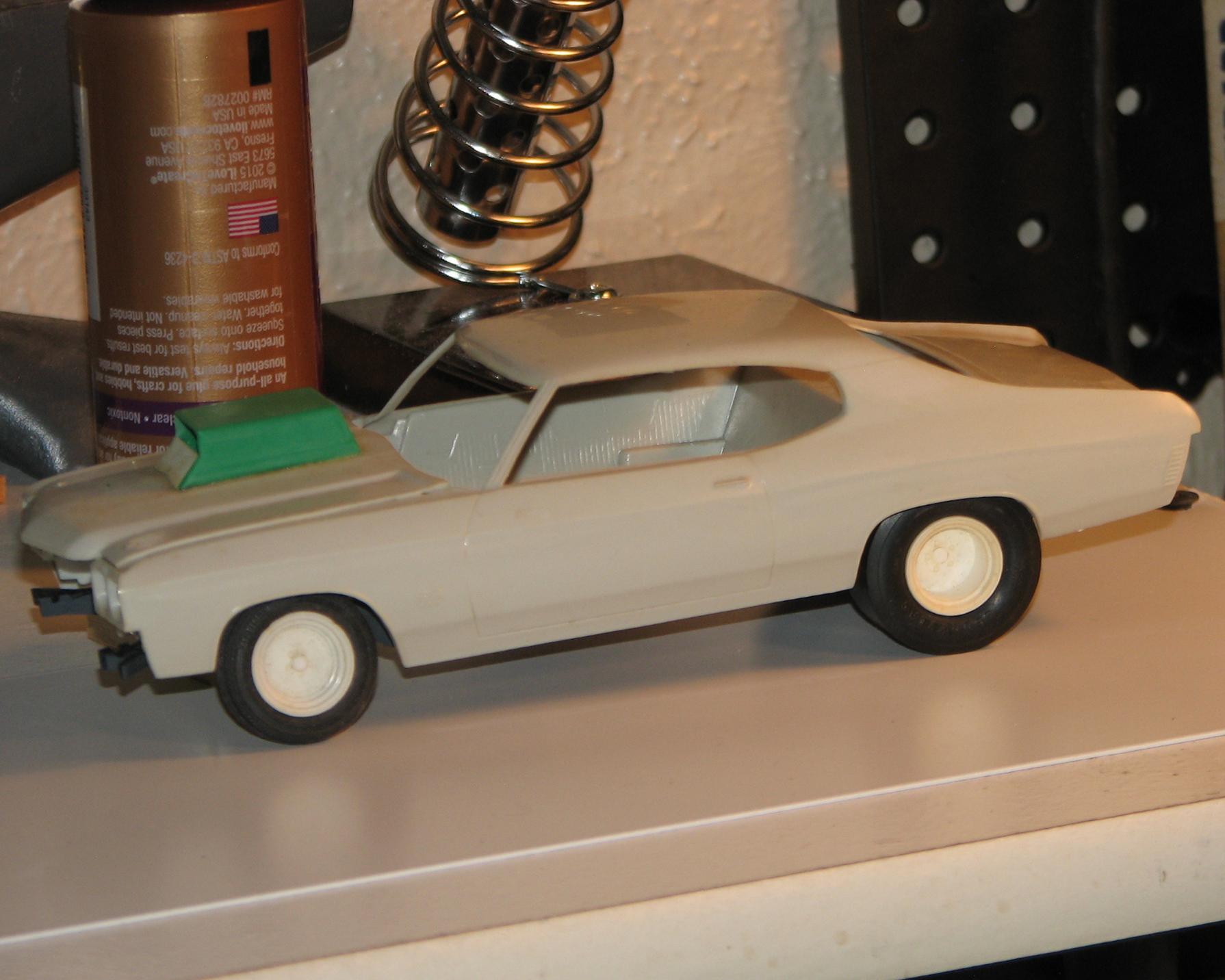
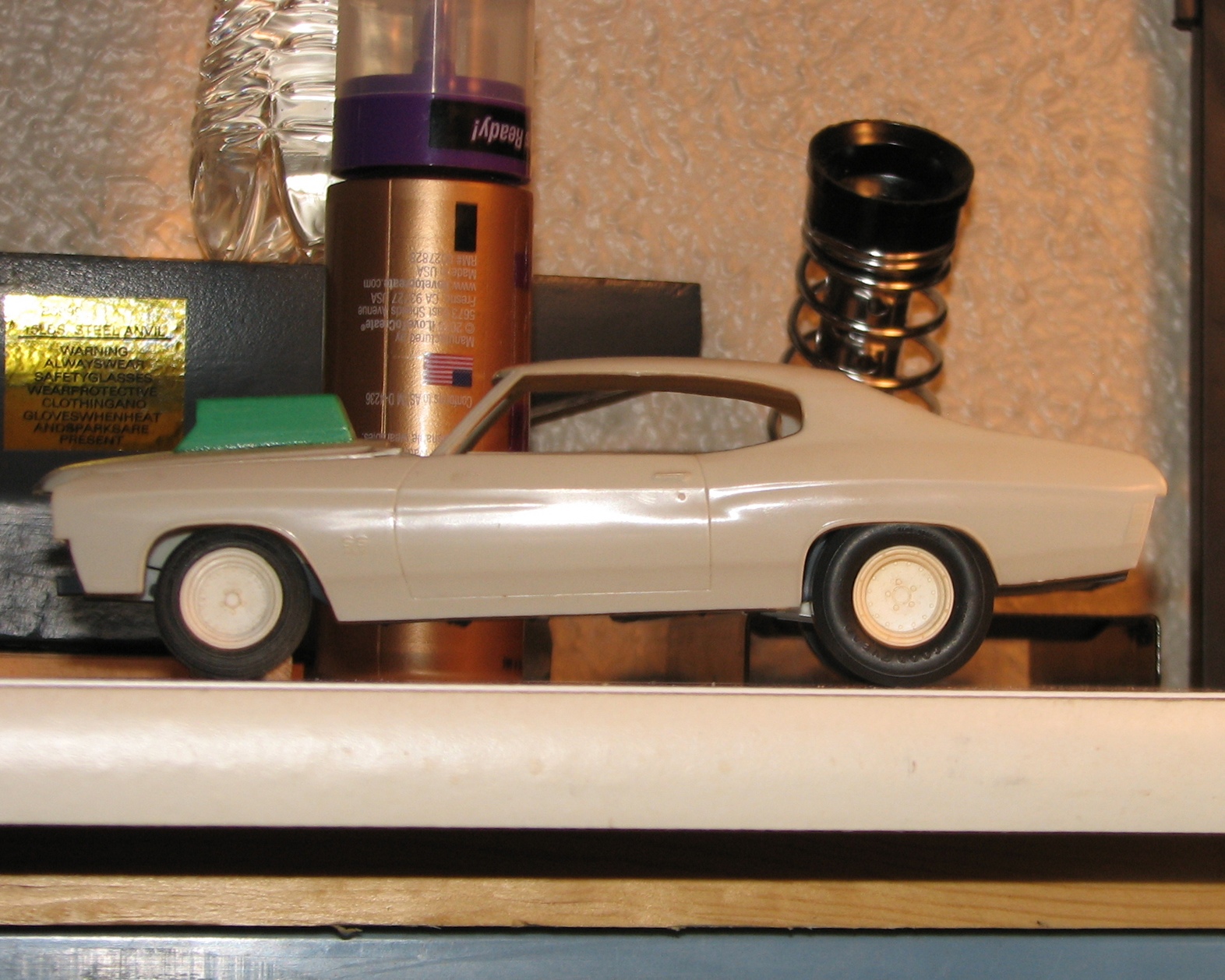
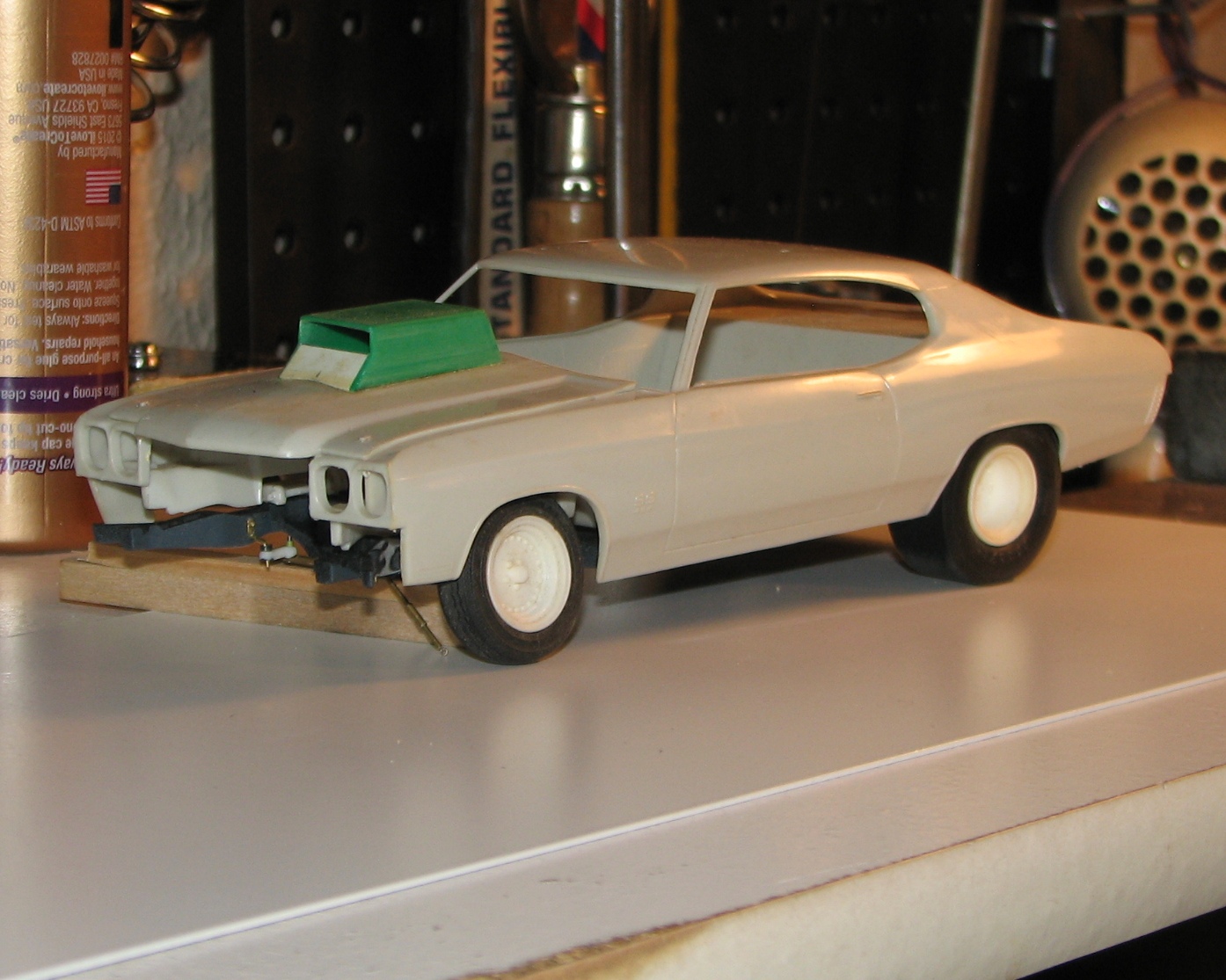
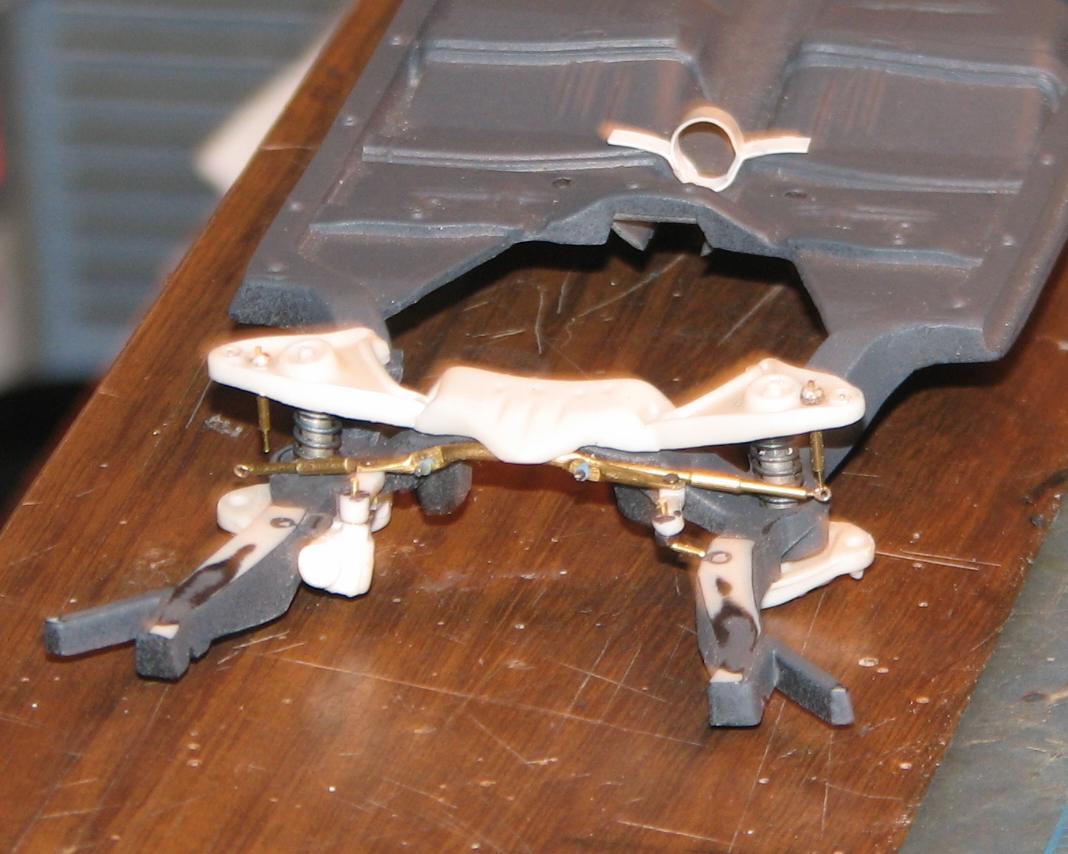
I've decided to go with the Revell SnapTite body. It's much nicer, and actually fits the AMT chassis better than the AMT body does--check the alignment of the tires/wheels in the wheelwells. It will work with the AMT interior tub (I favor it, because it doesn't have the rear seat, which is legal for MP, so long as the area's "finished"), which I will fit with the side panels from the snapper. I got two photos taken before the tacky glue bond came apart, and the front suspension collapsed--again! Can't wait until THAT assembly is finally assembled and mounted. Alas, that's going to be a while, yet...
-
That front suspension is beautiful work, and will paint up nicely! That Revell SnapTite Chevelle is a really nice kit, and is arguably the most accurate '70 Chevelle body we have to work with. It wouldn't take alot to open up the hood and use over a full detail chassis. It gets points in my book for being in God's Favorite Scale ; 1/25. Still, there's something satisfying about beating the old AMT body into shape. Will be watching...
Thanks for the kind words, re: the suspension. I think I have about 30 hours in it, and that might be conservative! I am still interested in seeing your rear window treatment. I started working on mine, but am not sure I'm going about it correctly. The body sides don't look to be too difficult to correct. That said, I am giving the Revell body some consideration. Here's the car finally on the wheels...
-
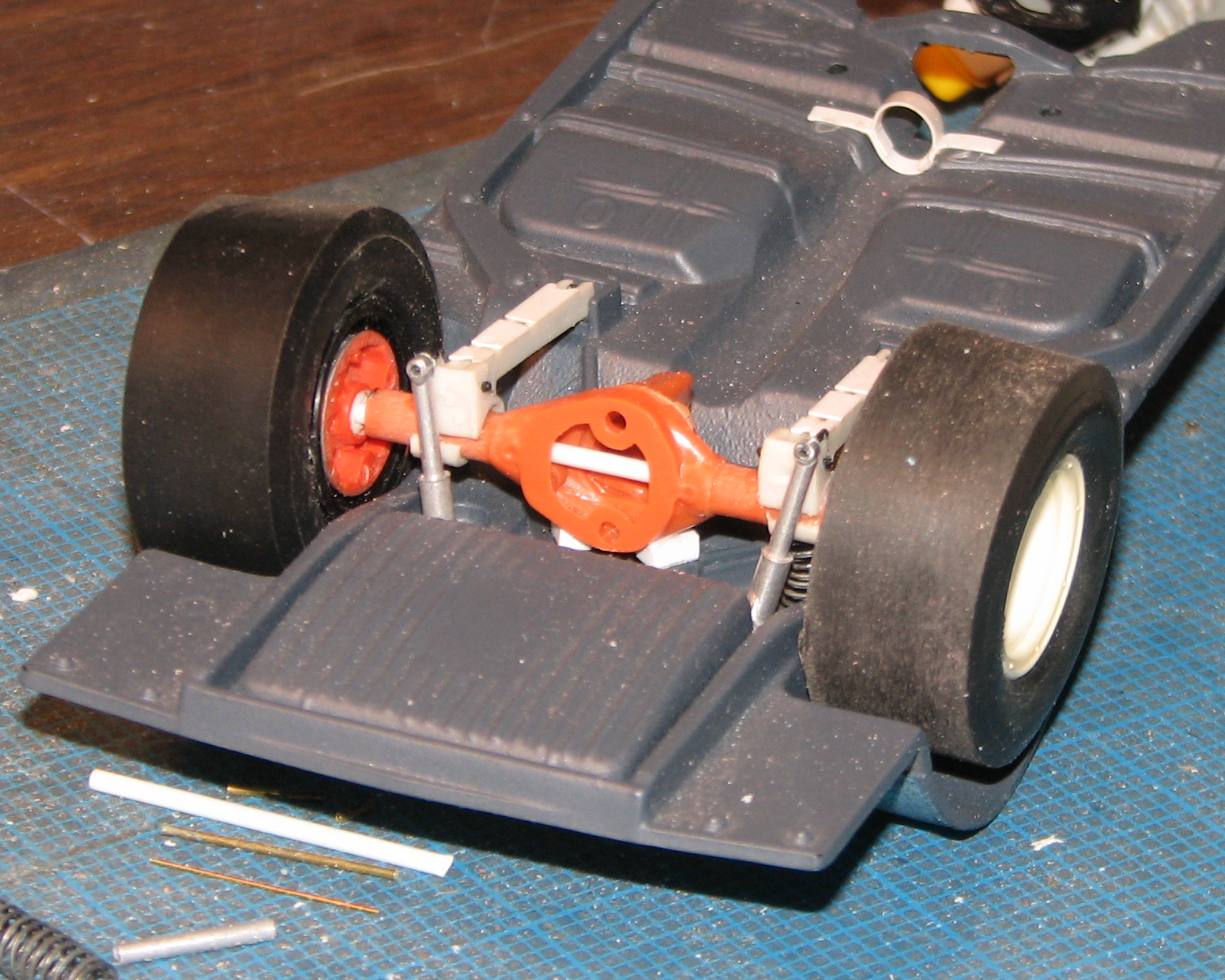
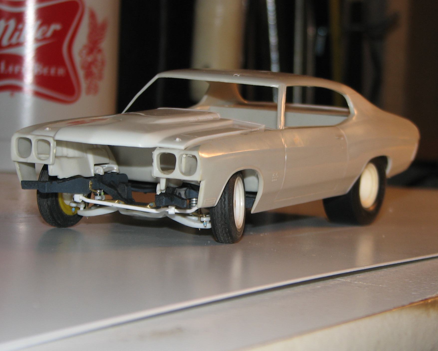
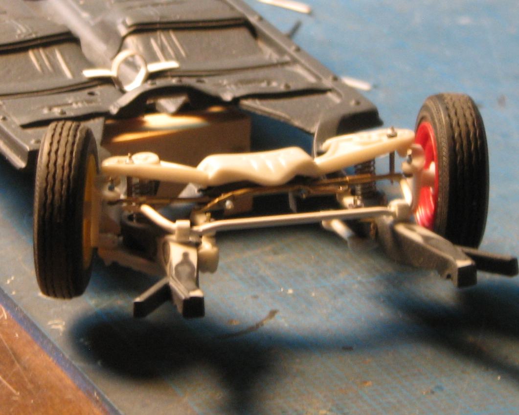
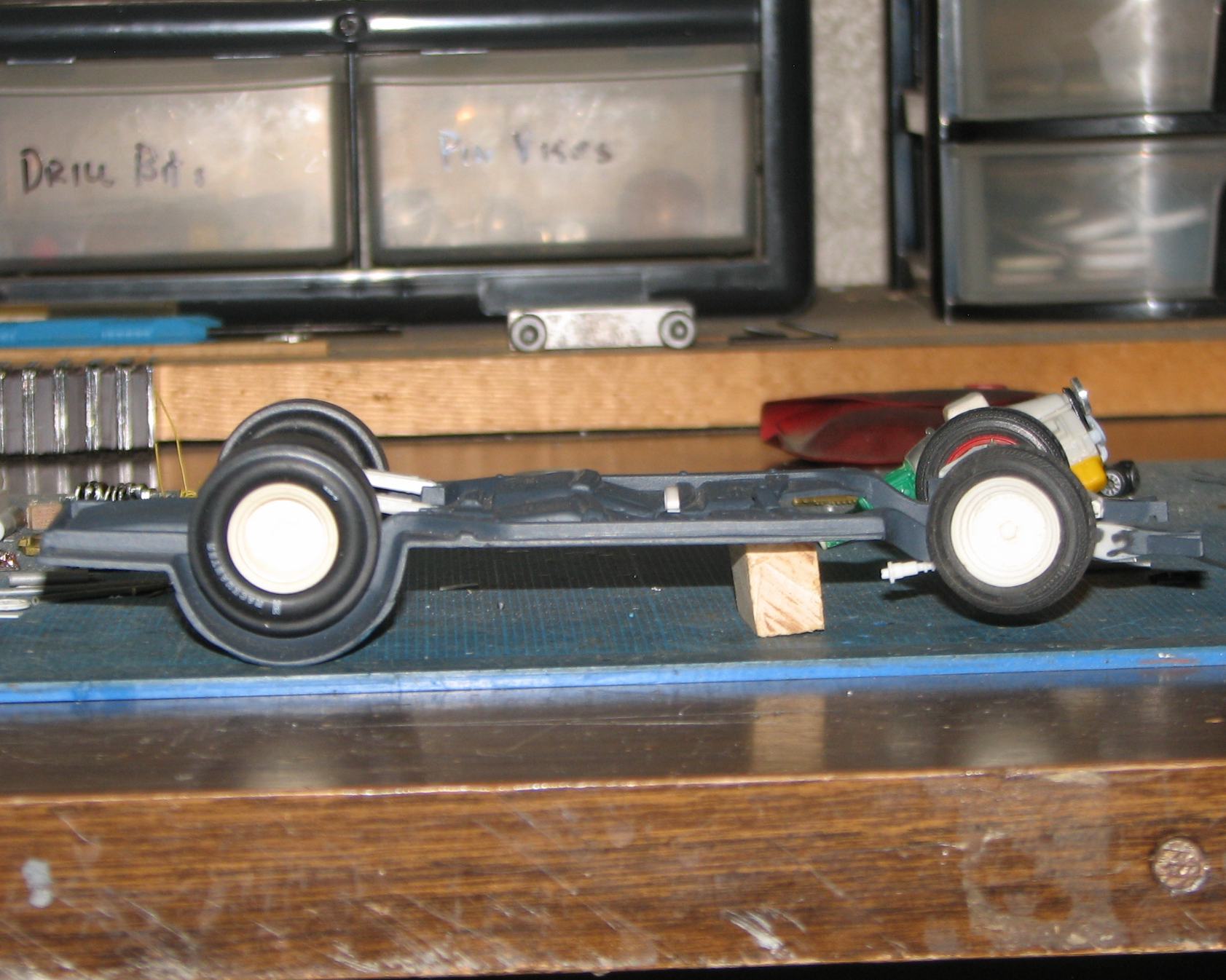
For the first time, I have all the wheels on the chassis. I'd say the chassis was on the wheels, but I forgot to tacky glue the lower A-arm assembly to the chassis, so this will have to do, for now. Next up, I will turn the front rotors, and get the front brakes set up. I haven't yet decided on discs or drums, for the rear.
-
How's the Revell body? I picked up one of their snap kits, today, and that body doesn't have the side issue, at all. Looks great, in fact, in that regard. The character lines just fade down into the fenders. If I am going to go through all this work on the front suspension, then, it's pretty important for the body to be right.
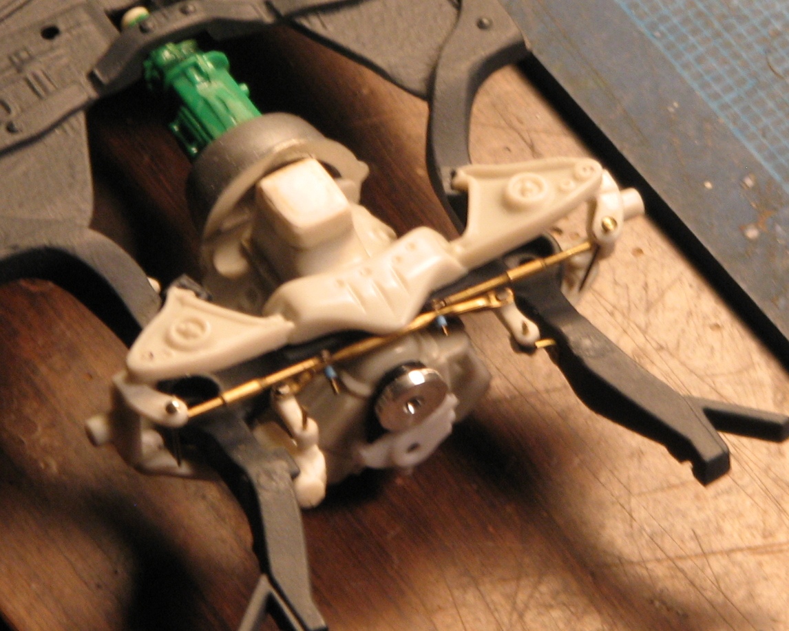
Ordered these nuts and bolts, online. I think I am going to use them to do the final assembly on this suspension. Yeah, they're tiny!
-
Sounds great! I see it, now that you've explained it. It is almost undetectable, in photos of the car, and I went and looked at a bunch of them. I am looking forward to seeing your work on the corrections. I have a Monogram kit, too, so I'll get it out and take a look at it. Thanks for taking the time to help me with this!
-
Such nice front suspension work! I'm working on a 70 AMT body at the moment, trying to correct the sides; lots of filing/sculpting! Will you be working over the body mistakes as well?
Thank you for the kind words, uh, Rusty. Or should I call you Dale?grin I'd like to see what you're doing. I'm mostly a dragster guy, and don't always see the things that are wrong with body lines, etc., of door cars, so I'd welcome a few pointers, if you're willing to help me out.
-
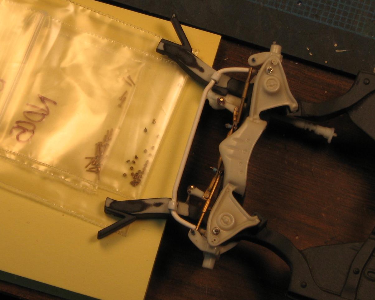
A little progress. I discovered that I didn't like the stance, once the slicks were in place. The rear of the car sat too low for my liking, so, I carved a couple of .080" blocks for the upper control arms. These effectively raised the car two scale inches, and it made all the difference I needed!
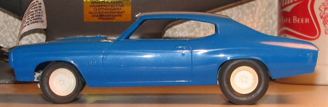
Also, you can see the front shocks and springs in place, and the steering, with the fasteners cleaned up. Also visible, on the lower A arms are the "standoffs" for the sway bar. Most of the work is done on the driveshaft loop, as well. Growing ever closer to chassis paint! Speaking of which, I ordered a can of Mulsanne Blue, for the body. I have also discovered that I have no need for the scoop, so will simply borrow the stock hood from another kit.
-
Thanks, Wayne! Nice start on your S/C digger!
-
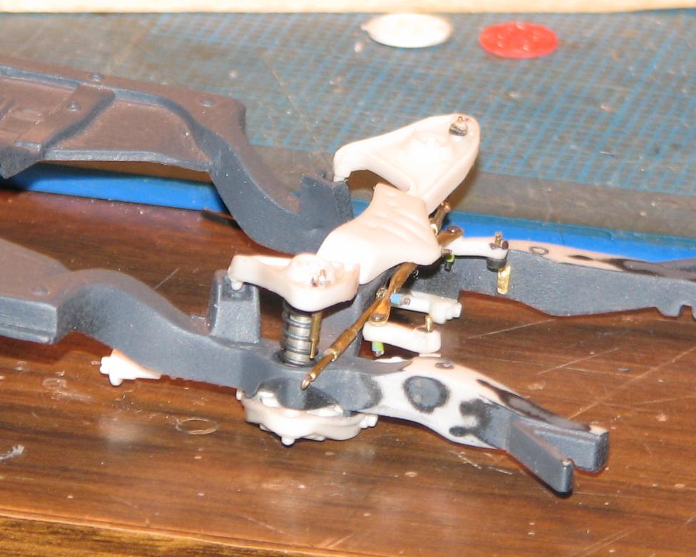
It doesn't look like a lot of progress, but, every time I have to take it apart and reassemble it, it takes at least an hour. That's due to the three sections of the tierod wanting to go three different directions, and the fact that it operates with very little friction, so, those sections don't stay where I want them! Trying to pin it back together is something akin to attempting to shove a piece of cooked spaghetti up a wildcat's ass! Anyway, it's getting closer to being ready for paint on the chassis, and getting all the fasteners trimmed and cleaned up! As soon as I can safely turn the chassis right-side-up, I can double-check the stance--exciting stuff!
-
Very interesting method, Daniel! Have you ever had any trouble with those bits of insulation coming loose from the distributor when you remove it from the mold, or when you insert the plug wires?
Not so far, and I've been using this for many years. The casting material somewhat encases the insulation, holding it securely.
-
Thanks, guys. I hope this method comes in handy! Ray, I like the idea of representing spark plugs. They're a frequently overlooked detail that some engines (especially flatheads!) require.
-
I haven't made a lot of visible progress on the Malibu, but, I just posted a tutorial/how-to for pre-wired distributors, here:
-
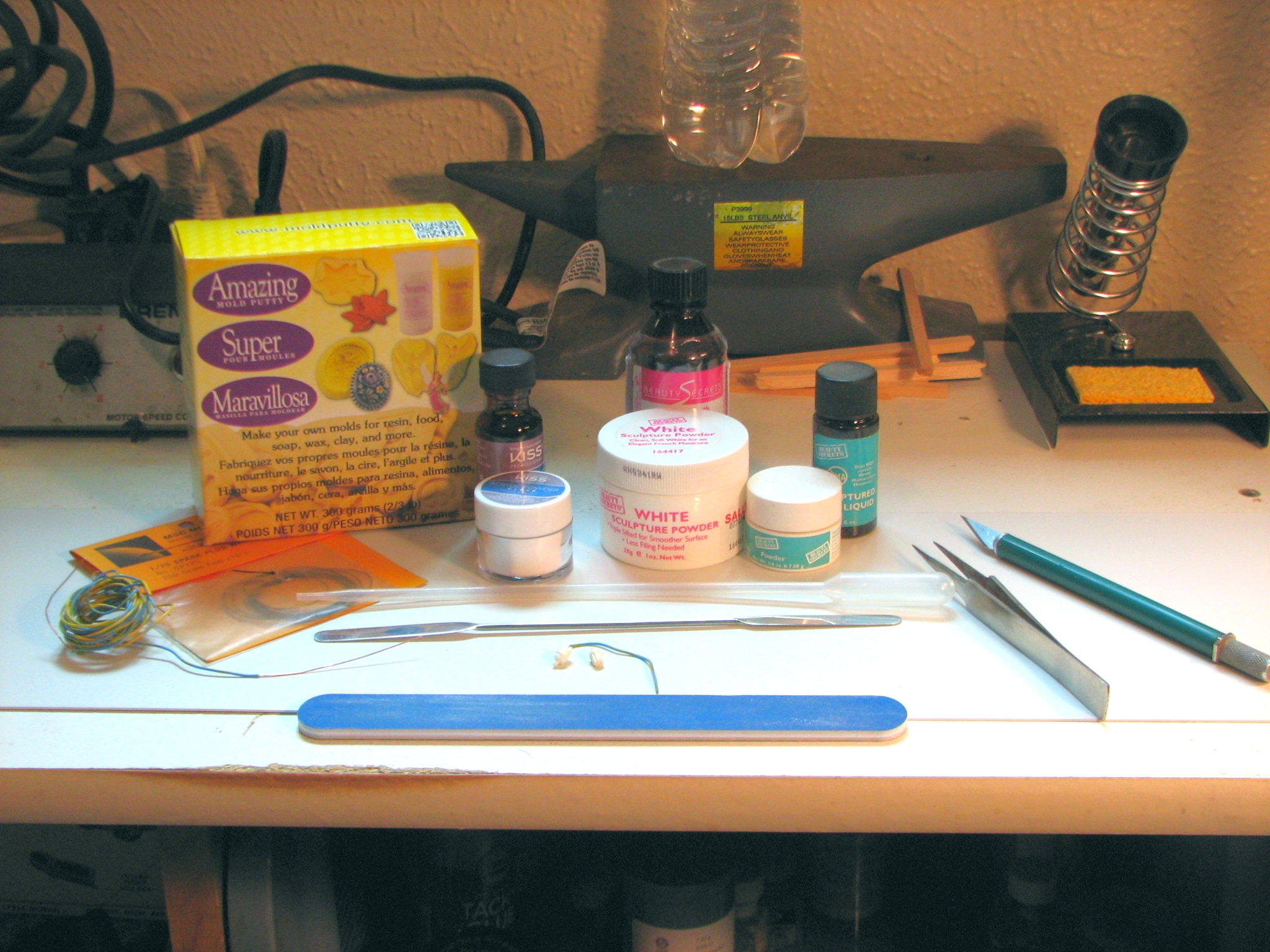
I mentioned this in the thread for my 1975 NHRA Modified Production '70 Malibu. It's a quick and easy way to make pre-wired distributors using readily available, and fairly inexpensive supplies. Begin by assembling the tools and supplies required (chefs call it mise en place). The first photo shows what you'll need. I got my mold putty through Amazon. It's made by Alumilite, so it's likely that Hobby Lobby has it, as well. You'll also need acrylic nail sculpting compound. It's a two-part system that is available from Sally Beauty Supplies, or, the Kiss brand is available in Walmart (at least those with larger cosmetic sections). The rest is stuff you likely have on-hand. Items include X-Acto knife, tweezers, sanding board or sandpaper, phone wire (or equivalent sized vinyl tubing), your choice of scale plug wire, a dropper for the acrylic liquid, a spatula to transfer the acrylic powder, super glue (I prefer a gel type, for this application), and a distributor with pronounced "lug" detail.
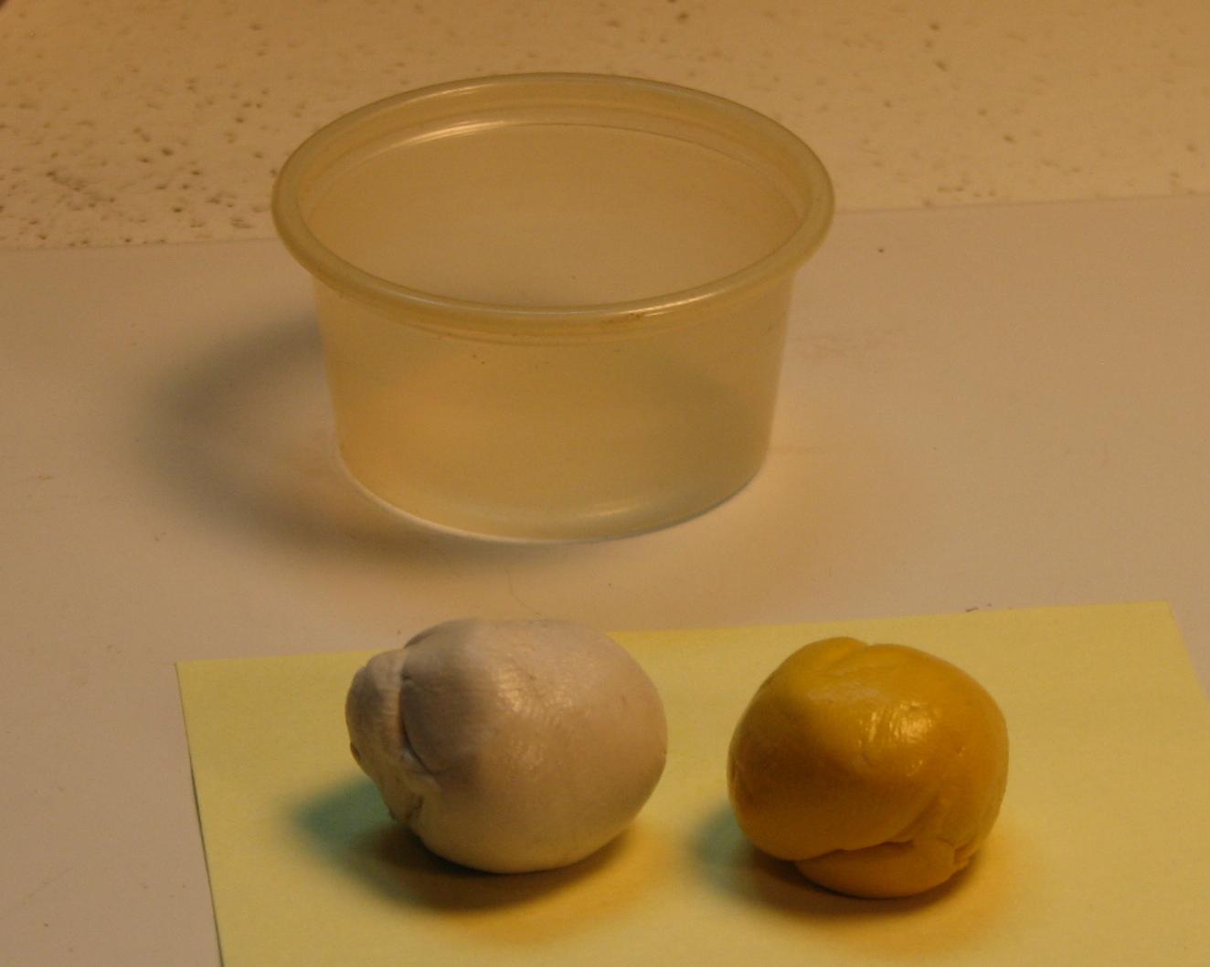
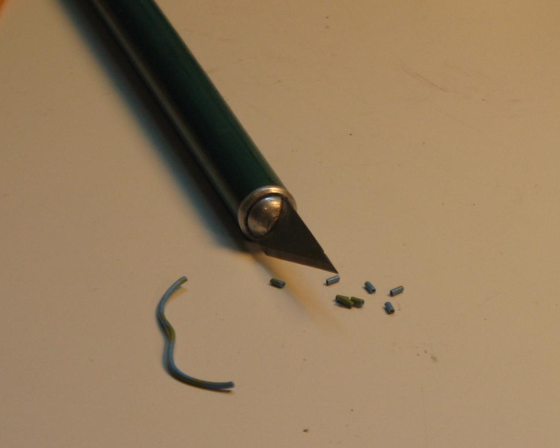
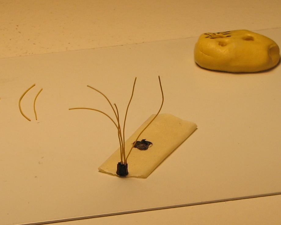
Begin by mixing equal parts of the mold putty. A note about the Amazing Mold Putty--it's non-toxic and food safe. That's always a good thing! Once the putty's mixed, press the ball onto a flat working surface, insert the kit distributor, top down, and wait. The putty will cure in 15-20 minutes (to ensure a quicker cure rate, I usually pull a desk lamp down near the mold, to provide a bit of extra warmth to the reaction). Now is a good time to cut the wire insulation into lengths of about .100". You can also cut your plug wires now, too (just be sure to cut them long enough, so that they'll fit your engine of choice.).
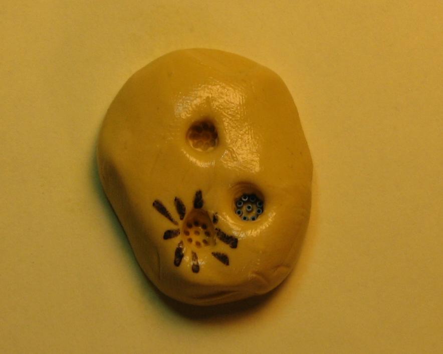
Once the mold has cured, remove the kit distributor from the mold, and check the mold for imperfections. Bubbles aren't a problem with this putty, so, your mold should be ready to go. Now, begin inserting the wire insulation into the depressions inside the mold. Be sure they are aligned properly--they should plug right into the holes. Continue until all the holes are "plugged".
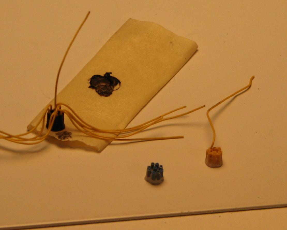
Next, draw a small amount of acrylic liquid into a pipette or dropper, and flow it down the inside edge of the mold, until it covers the bottom of the mold. Follow the liquid with a small amount of acrylic powder. Repeat this process until the mold is topped off. Wait...the acrylic resin will cure in a few minutes. Again, the lamp can help to speed the reaction.
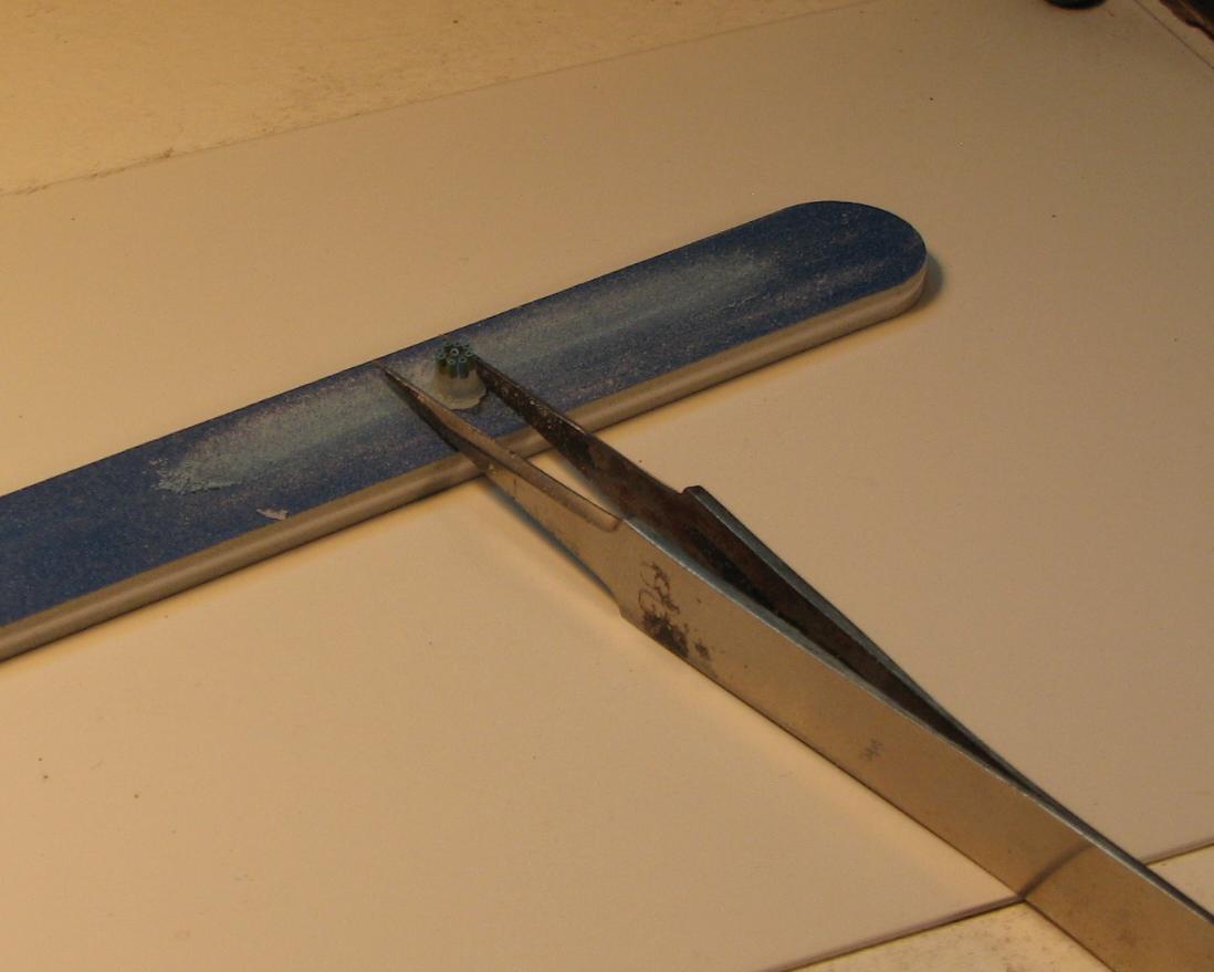
Pull the new distributor from the mold and inspect it. If it's satisfactory, grasp the distributor with pair of tweezers, and work it back and forth across an abrasive surface (sandpaper or a sanding stick), rotating it in the tweezers every few strokes, to keep the bottom level. Once it's sanded flat and smooth on the bottom, the distributor is ready to finish, and add plug wires to.
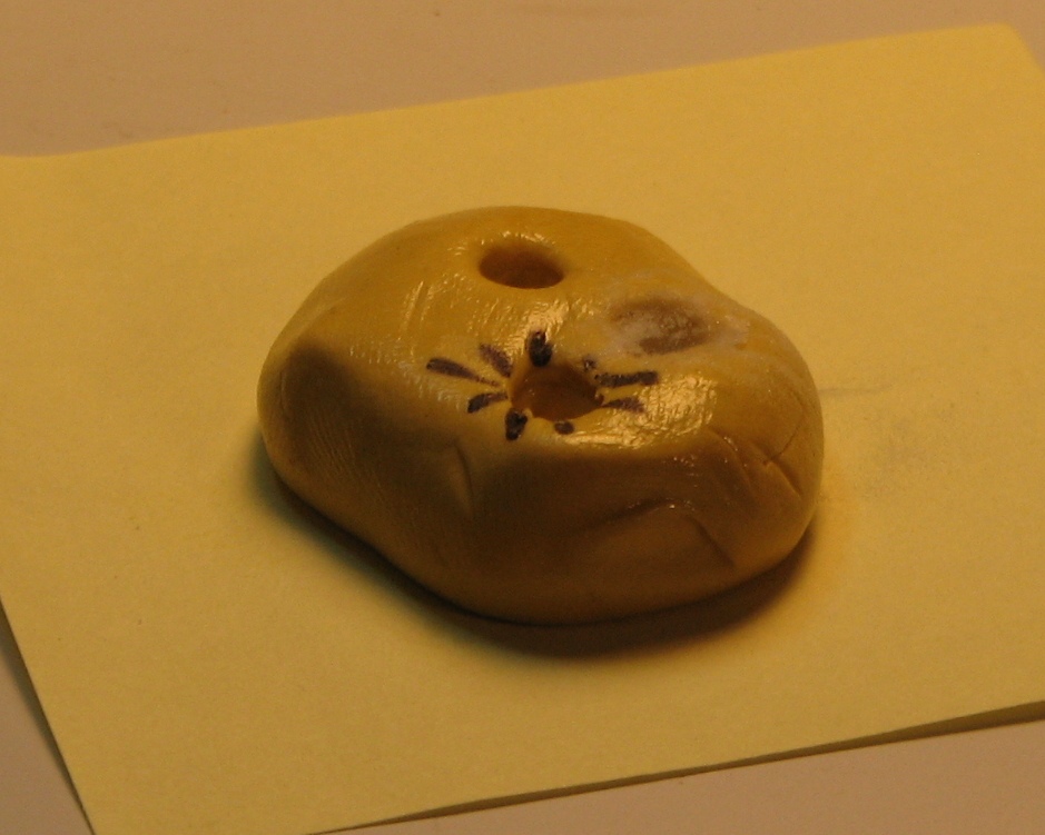
Paint the cap to represent the brand you want it to be (Accel, Mallory, etc.). When the paint dries, dab the tip of a length of plug wire with super glue, and slip it into the hole in the end of a piece of the wire insulation, which has become the nipples on the cap of the distributor--and they all have a perfectly sized hole for the insertion of the plug wires! Insert all nine plug wires (for a V-8), attach the cap to a distributor base, and mount it to the engine. Now, simply run your plug wires home and you're done!
For a minimal investment in materials and time, you can create a mold that will provide many distributors for wiring, without the difficult and often frustrating task of drilling all those holes without blowing out the side of a distributor, and ruining it, and wasting all the time you spent on it, up to that point. Hope you all find this helpful and informative! Comments and questions are welcome!
-
 2
2
-


Revell '34 Ford three window
in WIP: Model Cars
Posted
Thank you for the kind words, Terry and David! I am pretty happy with its overall look, as well as the way some of my experiments worked out. Hoping to finish it today, and post a thread for it over on the Drag Race forum!