futurattraction
-
Posts
1,647 -
Joined
-
Last visited
Content Type
Profiles
Forums
Events
Gallery
Everything posted by futurattraction
-
LOL. If I was doing all this only for myself, I probably would be a bit more relaxed in the way I approach it, but since I want things to be as close to "right" for anyone interested in eventually buying any components, I feel like I need to make the extra effort to make things as "kit like" as possible. Oh - I fishmouth almost exclusively - any place that the joint is visible. As far as tubing or rod, It depends on what I'm building, what dimensions are available, and how it's all going to fit together. In the thread on my Fairmont, I originally used thin wall 5/64" (.078) brass tubing, with 1/16th tubing telescoped inside it. The new forward chassis I'm building is made out of similar diameter styrene rod made by Plastruct. I'll try to detail the "why" of my change in direction when I post on my Fairmont thread, but suffice it to say, I changed media because of what I was trying to accomplish. I almost exclusively use CA glue. I need to broaden my gluing horizons because I know I could have better control of certain situations if I were to use slower setting adhesives. Another area to grow in, I guess... LOL
-
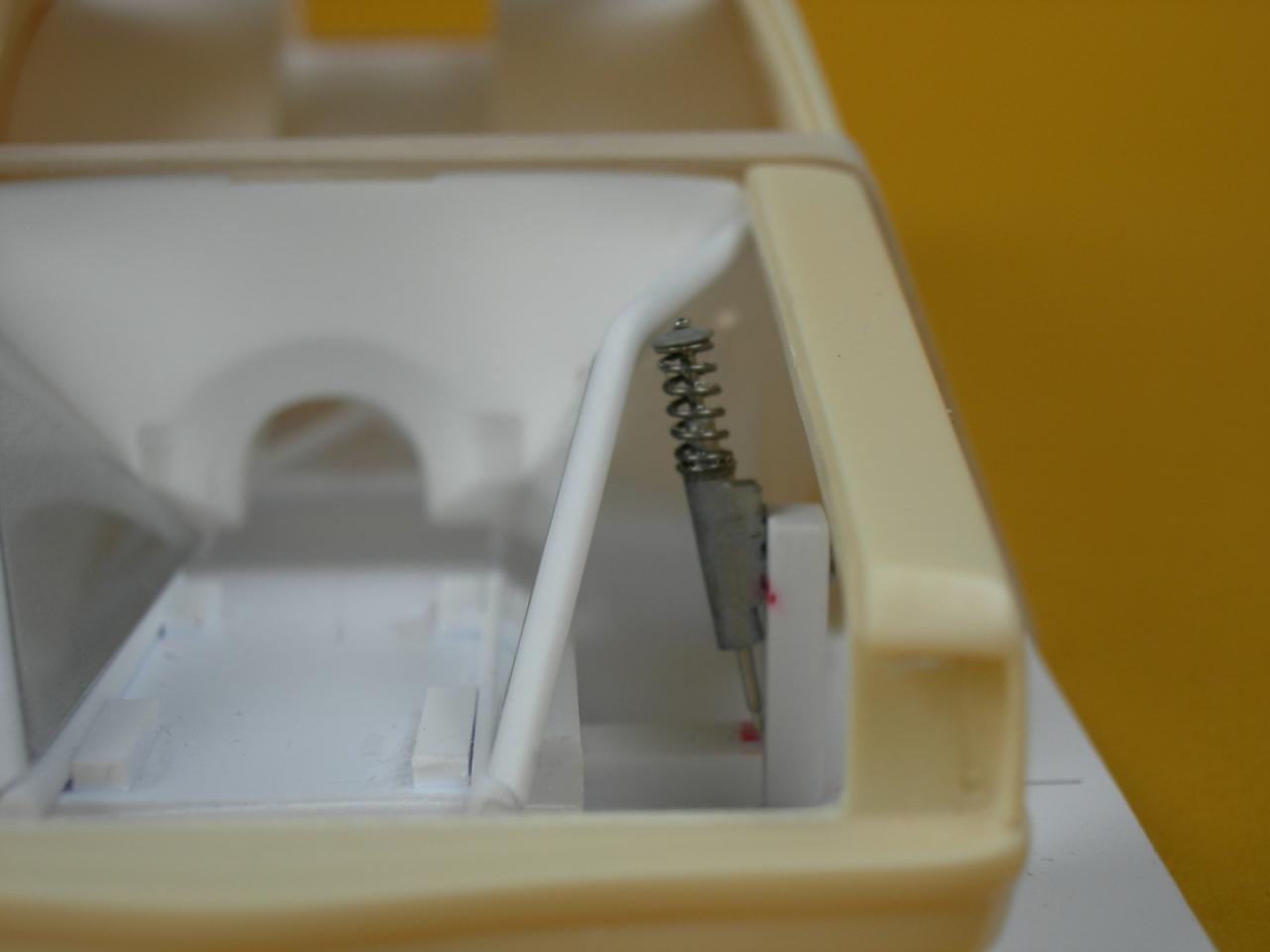
Hey Ted. Thanks for the feedback. I actually got in touch with Dave (comp1839) and asked him what type of caster is typical for a doorslammer. He replied in the area of 8-10 degrees. I'm trusting that that spec hasn't changed too much over the past 30 years. LOL Because of my PE drawing, I have a CAD program, so it was simple for me to draw the template angle I was shooting for, then simply print it out, cut it out, and lay the template against the front edge of the strut to set the angle. The spindles have a slight interference fit in the spindle blocks so they hold the angle pretty decent. Since I took the pics, I've actually added upper mounts to the splash shield/tubing assembly. (I'll explain more of that when I resume my Fairmont thread.) The next step, then, will be to build a front crossmember-gusset assembly to set the final width of the rails and triangulate the forward rails. I am going to cast the splash shield/tubing so I can remove the temporary fixture holding the frame rails at the angle I was needing. I have some scrap floor pans that I'll probably sacrifice one of them to the cause and glue a completed resin forward rail assembly to the pan so I can work upside-down with the body to see what the heck I'm doing with the lower control arms. My plan, barring any goofs, will be to add some type of locating nub to the frame rail that will serve as a locator for my foldable chassis tabs, which will accept RB Motion rod ends. I've developed a lower control arm "wishbone" that will tie the bottom of the strut body and both sections of control arm together so they're integral with each other. Those will be shown in my Fairmont thread at some point in the future... Thanks Tom. I'll try to get back to that real soon. I'm starting to feel like I'm digging out... LOL
-
Here's the link: http://www.modelcarsmag.com/forums/index.php?showtopic=62293&hl=fairmont As I mentioned above, I'm planning to get back on it very soon. Chores at home, some misguided eyeballing on my part, and a couple of discussions with fellow modelers have caused me to go in a different direction than originally intended, but I'll leave that explanation to the thread when I get back to it... LOL
-
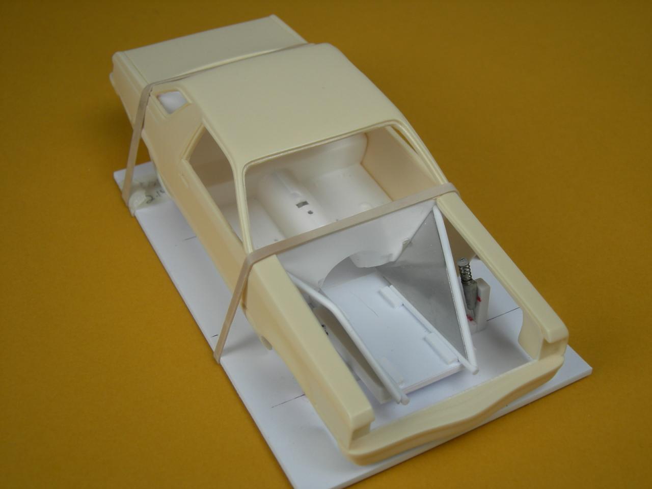
Ted, I know your question was aimed at Joe about locating front suspension points, etc., but I wanted to show you what I'm doing on my Fairmont suspension. I'm going to pick up my thread from back in August on this shortly and will include some of these pics, but wanted to show you how I'm establishing those points, as long as the thread pertains to this subject. I'm sure others will have different ways of doing it. I measured the diameter of the front tires I'm planning to use, drilled spindle blocks that match the tire centerline and so the spindles are parallel to the ground, determined track width and fore/aft location within the wheel well opening. I then glued the spindle block to a styrene base. Once the block was in place I could set the caster where I wanted it. The upper tubing ties into the firewall and was dictated in large part by the shape of the aluminum tinwork that is integral with the tube frame members, which I had to fuss with. I am going to work on the lower mounts next, but haven't gotten that far yet.

-
Paint looks super and the stance will be killer!
-
 Your 5-7 is looking super, Joe. As Jim said, I've got to remind myself that I'm not looking at a 1:1...
 -
Revell '57 Ford Custom 2'n1
futurattraction replied to MachinistMark's topic in Car Kit News & Reviews
I checked at my local HL a few days ago. They've got a label on the shelf for it, but no kit. They did offer to order a couple for me, which they've done, but they're not in the warehouse yet. They said they'll keep ordering them 'til they get them in. They even made a note on the special order tag that I would use a 40% off coupon for the purchase of each of them. Now, I've just gotta wait! -
Anybody want a Liberty Transmission?
futurattraction replied to TedsModeling's topic in Car Aftermarket / Resin / 3D Printed
Ted, I was finally able to get dimensions off a 5-speed and am going to start working on both the trans and PE shifter. -
Revell '57 Ford Custom 2'n1
futurattraction replied to MachinistMark's topic in Car Kit News & Reviews
That was fun to watch, Virgil. Thanks for sharing. I'm really looking forward to seeing these in our local HL and/or Michaels. -
1-8 scale 69 camaro pro mod (mike hill's car)
futurattraction replied to comp1839's topic in WIP: Drag Racing Models
Looks super, Dave. I'm looking forward to more pics of your 1:1 as well as your Camaro... -
I'm noting that everyone is cautious about how they describe your rear end, LOL. And I will, too... You've done a fantastic job in assembling it - it looks super. Your coil-overs are a work of art. Keep up the awesome work, Joe!
-
1/16 Scale Army Vega Funny Car - Finished 10/14/2018
futurattraction replied to Mooneyzs's topic in WIP: Drag Racing Models
Your attention to detail never ceases to amaze me, Chris. As I recall, plug gaps are super-wide on nitro engines aren't they? ;-) -
Super looking job, Steve. Your machine work looks outstanding! She's coming along great...
-
57 chevy pro mod w.i.p (updates 11/11/12)
futurattraction replied to tyrone's topic in WIP: Drag Racing Models
That is drop-dead gorgeous, Tyrone! Your paint looks like it turned out flawlessly and the overall detail you put into your builds is over the edge. -
making resin engines
futurattraction replied to alarmstrong's topic in Car Aftermarket / Resin / 3D Printed
This is how I've been casting my engines. Block and all components are cast as individual pieces. Some are tougher to do than others! LOL If you have any questions, feel free to ask...
-
Yes - absolutely. More engine pics would be much appreciated...
-
57 chevy pro mod w.i.p (updates 11/11/12)
futurattraction replied to tyrone's topic in WIP: Drag Racing Models
That is SOOOOOO COOOOOL. She looks absolutely stunning, Tyrone. -
Something I failed to comment on that someone else mentioned is the different materials you used for the blanket straps that really set them off and add a whole 'nother level of realism to your trans, Joe. I'm looking forward to your updated pics...
-
Your trans and clutch can look fantastic, Joe. I'll look forward to seeing more progress soon!
-
57 chevy pro mod w.i.p (updates 11/11/12)
futurattraction replied to tyrone's topic in WIP: Drag Racing Models
That black paint looks sinister,Tyrone. I love it!!! LOL -
Though the work you've been doing recently has been tedious, it looks fantastic, so it's worth the time... Keep up the great work!
-
1/16 Scale Army Vega Funny Car - Finished 10/14/2018
futurattraction replied to Mooneyzs's topic in WIP: Drag Racing Models
Your MC looks great and the updates you've made to your engine look super, Chris. -
Late Model Mustang Pro Sportsman
futurattraction replied to limoman39's topic in WIP: Drag Racing Models
That's looking great, Rick. I love all the detail you're putting into it... -
1966 Chevy 2 outlaw updates 02/10/13
futurattraction replied to tyrone's topic in WIP: Drag Racing Models
Look super, Tyrone. Opened up rear wells look perfect! -
That's turning out really nice, Steve. What OD were your butterflies? I may be missing something but on your lower coil-over brackets, it looks like they have only a pivot point where they connect to the housing bracket, which makes it seem as though they "float". That doesn't make sense to me. Is there another piece that will be added to tie them solidly into the housing bracket? As I said, I may not be seeing something but am just curious... Your coil-overs look super!