beeRS Posted September 17, 2022 Posted September 17, 2022 Fantastic work. I love the super detailing and opening panels. Keep the updates coming - I’m enjoying this.
dino246gt Posted September 17, 2022 Posted September 17, 2022 Awesome modelling skills here, wow, I love this project!
Mattilacken Posted September 17, 2022 Posted September 17, 2022 Incredible! Those parts are so tiny so I can’t believe that you made the hinged fuel door and the tie down strap holders! Incredible. Great work on every detail!
CrazyCrank Posted September 18, 2022 Author Posted September 18, 2022 On 9/16/2022 at 1:48 PM, Modlbldr said: Wow! Amazing efforts to get the details right! You're doing a fantastic job on this beautiful little car. I've wanted this kit for quite a while but have yet to get it. After reading through this entire post I'm back on the hunt for one. Thank you! Later- Thanks Modlbldr, huge compliment, much appreciated ?
CrazyCrank Posted September 18, 2022 Author Posted September 18, 2022 On 9/17/2022 at 9:06 AM, beeRS said: Fantastic work. I love the super detailing and opening panels. Keep the updates coming - I’m enjoying this. Thanks a lot for the kind words. Stay connected 20 hours ago, dino246gt said: Awesome modelling skills here, wow, I love this project! I'm pleased you love it ! Me too ? Thanks for your praise 15 hours ago, Mattilacken said: Incredible! Those parts are so tiny so I can’t believe that you made the hinged fuel door and the tie down strap holders! Incredible. Great work on every detail! Yes I made them ! And if I can do it, everybody can, too ! Thanks for the huge praise ?
CrazyCrank Posted September 18, 2022 Author Posted September 18, 2022 (edited) Good evening guys: Since early September, I'm working on the design and 3D printing of the new dashboard fors this BMW 507 series 2. I finally achieved to obtain the right curves and dimensions, exactly the same the the kit part, what is mandatory to get a correct fit in the body. However, I faced some expected print issues with the first drafts ! It's a well known problem that the 3D resin print has the bad tendency to shrink and bend several hours after UV curing. The larger and thinner the part, the bigger the problem ! The just 3D print thing, before curing, had the same dimensions than the drawing. But after curing, from the first hour, the part shrunk and twisted, slightly first, and after 24 hours, this was much more important ! To such an extent that the part was no longer usable ! It seemed to me, according to my first observations, that this phenomenon is less marked if the piece is left to dry on its base with its supports. So I made a comparative table with Excel on this phenomenon, measuring the size at the exit of the printer tray, the presence or not of a curvature of the straight lines after drying, the size after UV curing, the size after drying on a base or not after 1 hour, 2 hours, 12 , 24 and 48 hours for prints at different scales: - 100, 101, 102, 103, 104 and 105%. And I also measured, in case of curvature of the piece, the size after manual reduction of this curvature, on the piece dried 24 and 48 hours. All this job has been is very time consuming, which explains my silence for several days. Some pictures of the 3D drawing, in its initial state (far to be achieved and complete). A few days later, my tests were not yet not finished but it was already possible to draw conclusions. On the photos below, you can see a comparison between : - On the right: 103% size prints left to dry almost 48 hours. On the rear it dried on its supports, and on the front, it dried free of supports. Design V7. - On the left: 103% size prints with the same drying conditions, but with a modified design which increased the thickness of the wall. Design Called V8 What we can see: - There is a curvature on the straight lower portion on the 4 drafts, - This curvature is much less important when the draft has dried on its supports. This is visible for the V7 and V8 drafts - And it's much more important on the V7 drafts (thinner wall) - The shrinkage is bigger on the V7 drafts which have thin walls than on the V8 ones, with thicker walls. - And the size reduction is significantly bigger for the drafts which dried without supports (about 3.5 mm vs 2.0 mm) Anticipating such results, I quickly decided not to wait more for incorporating on the design new structs on non visible sections, that strengthen the build and intend to prevent the bending. I took this opportunity to modify of the meters surrounding , to prevent the waves you can see on the picture above I printed this design 100%, 101, 102 and 103%, and measured the sizes just after printing, just after UV curing and then after 1, 2, 12 and 24 hours of drying. But, this time, I've left dried the 4 drafts on their supports, and the supports left attached on the printing plate. And the results were much more different after 24 hours : There was really no bending, and the shrinkage varied from 1.09 to 1.27 mm ? So, I went on with my tests ! I decided to let them dry in these conditions until 48 hours, and then to let them dry 24 hours more, but after detaching the supports of the printing plate, and at last 24 hours more free of all supports. And to measure the sizes and the hypothetical twisting at all steps. And this is how all that came out at the end: The V8 versions (wall thickness increased but no reinforcement structs), that dried after having been detached from the printing plate had finally, after 48 hours drying : - for those that dried over their supports a slight distortion and a average shrinkage of 2mm - And for those that dried without their supports a major distortion and an average shrinkage of 3.5 mm The V9 versions (wall thickness increased and reinforcements structs), had finally after having dry 48 hours on their supports, themselves attached on the printing plate, then 24 hours more with supports detached of the printing plate, and at last, 24 hours more detached of their supports: - Horizontal and vertical distortion: Absolutely none - An average shrinkage of 1.40 mm The draft which size has been increased of 3% in the slicer has a final size of 51.00 mm, when 51.04 mm is the theoretic expected size for an optimal fitting on the bodywork. Nevertheless, I made also tests with 104 and 105% drafts for 2 days. But it was now clearly evident that 103 or perhaps 104% are the good factors. Little size comparison between the kit part and the 3D printed one (103%) And I did a test fitting of the V9 103% on the windshield frame: As you can see, there was a lack of material on the left and right ends, so, I modified the 3D design: And I printed it in draft mode (50 microns layer) in 101%, 102%, 103%, 104% and 105% . After 4 days drying in the already described conditions, I got yesterday the final results of all tests, and here is what I can say about the resin 3D prints, their shrinkage and their tendency to twist: - With my last V10 draft, I incorporated reinforcement structs - I've printed 100%, 101-102-103-104 and 105% drafts - The prints dried 96 hours, 48 attached to their supports, themselves fixes to the printing plate, then 24 hours only on their supports and at last 24 hours free of any support. In this way, contrary to the previous tests without reinforcement structs or drying free of supports since the UV curing, there was absolutely no twisting, even after having detached the prints form their supports. And the shrinkage has been very moderate during the first 48 hours, and very low after. It reached an average of about 1.3 mm for all the sizes after 96 hours, of which 1.0 mm during the 48 first ones. The 103 and 104% prints are the ones whose size is closest to the required dimensions. I've made this afternoon a test fitting of the 103% and 104% on the windshield frame, where the dash will be glued, and the 103% is the best, at the moment (because I don't know what will happen in terms of shrinkage with the final prints in 20 microns layers) The lateral reinforcement structs had to be cut out for a good fitting of the dash and hereunder you can see some pictures I took in a hurry, after a temporary glueing (with canopy glue) of the dash on the windshield frame, and the frame just sat on the first bodywork (the broken one): Some little improvements have to be done on the 3D design before the final printing, but I'm now very happy of the way this turned out So, I'm now going to do this job and print several dashes in 103% at 20 microns layer, and let them dry the same way I described above. In the mean time, I'll glue the tub on the body and then cut out the doors ... Stay connected if you like Edited September 18, 2022 by CrazyCrank 1
Pico Posted September 19, 2022 Posted September 19, 2022 CrazyCrank, Thanks for your important research! 1
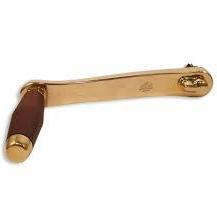
CrazyCrank Posted September 19, 2022 Author Posted September 19, 2022 Morning guys I've slightly modified some things and added 2 missing parts: - The ignition key housing, below the meters on the right of the steering column - The stand for the choke handle on the left end underside of the dash All that stuff has been sliced, 3 pieces in 103% and 3 in 104% . And will be printed today in 20 microns layers. Hopefully the prints will be as good as the previous ones ? See you soon 1
BVC500 Posted September 20, 2022 Posted September 20, 2022 (edited) On 9/19/2022 at 5:03 AM, CrazyCrank said: Morning guys I've slightly modified some things and added 2 missing parts: - The ignition key housing, below the meters on the right of the steering column - The stand for the choke handle on the left end underside of the dash All that stuff has been sliced, 3 pieces in 103% and 3 in 104% . And will be printed today in 20 microns layers. Hopefully the prints will be as good as the previous ones ? See you soon Impressive. Would you be willing to share your file, or make the part available for purchase? I'd love one for my 507. I like the Series 2 dash much better. Edited September 20, 2022 by BVC500 1
CrazyCrank Posted September 20, 2022 Author Posted September 20, 2022 (edited) 4 hours ago, BVC500 said: Impressive. Would you be willing to share your file, or make the part available for purchase? I'd love one for my 507. I like the Series 2 dash much better. Thanks for this comment @BVC500, much appreciated I'm going to make the part available for purchase. But, I'm still going on with my tries. After having measured the shrinkage of the prints when time passes for my drafts printed in 50 microns layers, I've just printed my final version V12 in 20 microns layers at 103 and 104%, percentages that seemed to be convenient . The print is absolutely perfect, just when I've cleaned it and after UV curing. BUT, there' always a "but"...After curing, the shrinkage was insignificant and 2 hours after curing, it's only 0.2 mm when it was about 0,75 mm for the drafts at 50 microns ! I've obviously to wait the next steps: 12 / 24/ 48 /72 hours drying to see if it will increase or not, and in which proportions. Anticipating a insufficient shrinkage with the 103 and 104%, which wouldn't allow to reach the exact size I need (about 54,3 mm +/- 0,2), I just launched a new print in 101 and 102% . Decidedly, 3D printing technic parts with 3D resin isn't an easy task ! So, @BVC500, you will understand that I can't sell these parts until I have found the exact percentage increase in size to be applied during the printing process so that after a long drying time of 72 to 96 hours under the conditions already described above, the part will have the required dimensions of a few tenths of a millimetre to fit the windscreen frame perfectly. Well, not a big problem, it's just a question of time and tries Be patient Edited September 20, 2022 by CrazyCrank 1
CrazyCrank Posted September 22, 2022 Author Posted September 22, 2022 Afternoon guys While my tests on 3D printing the dash are going on, I've begun to think about the doors hinges. Initially, I thought I would be able to fabricate and install the door hinges after having glued the tub inside the bodywork , but my recent tests show that it will not be possible (for me) So, I've begun to work on them. My goal if to get an accurate and real cinematic when opening the doors, I mean, when you open the door of a car, its front edge enters the bodywork instead of moving away from it. I thought deeply and seen some inspiring videos on Youtube and ... let's go ! As a precaution, I'll do all my tests on the first broken body, which I reinforced for the occasion so it won't break again. And here is the current state The hinge has been fabricated with brass tube and 0.5 mm steel wire, a piece of styrène drilled twice 0.6 mm. The axle of rotation is situated on the inside of the door, on the front edge, that has been thinned of 50% (I've dig a groove at this place) The few point is inside the body, in front of the door. A lot of adjustments had to be done, and, temporarily, the position of the styrene piece which goes inside the bodywork has been modified and maintained with adhesive gum (UHU Patafix) It open smoothly, without catching ! Now, I've to improve the system, always on the broken bodywork, modifying the styrene piece (Increase its size, modify shapes) in order to avoid the adhesive gum and glue it in place definitely to test the system. If all's OK, I'll be able to fabricate 2 final hinges for the new bodywork in the same way BUT, there's always a but: I shall not leave the unfinished and unpainted doors definitely glued on the unpainted bodywork. Indeed, to finish the doors, with their inside face, le filling of the gaps on the front and the rear between the door and its inside, and to paint them, they must be free, and I must have glued the tub inside the bodywork BEFORE, in order to adjust correctly the inside of the door so it fit well with the tub. So, it's only once that done (the bodywork painted, the tub achieved and glued etc) , that l can put and fix the finished doors, and for that, I will only have a very little free space between the bodywork in front of the door, and the side wall of the tub at this level, to insert the two pieces of steel wire of the hinge into their respective holes on the styrene piece. It will be a difficult and painful job, assuming I get there ! If anybody see a better and easier solution to this problem, I'll be happy to have him exhibit It ! ? See you later
CrazyCrank Posted September 23, 2022 Author Posted September 23, 2022 Afternoon guys I publish always my builds on several sites, and a French modeler, friends of mine, pointed out that I was wrong about the door opening kinematics of the BMW 507 !!!! And, by the hell, he is right ! On his car, when you open the door, the front edge doesn't enter the bodywork as I thought mistakenly. On the contrary, the front edge of the door swings outwards when it is opened ! And he posted 2 photos and a drawing to show me how it worked on this car: It will be much more easy now with this knowledge, to fabricate the hinges and install them So I go back to my bench to fabricating theses hinges and test them on the broken bodywork Stay connected
CrazyCrank Posted September 24, 2022 Author Posted September 24, 2022 (edited) Evening guys A bit of progress today: 1/ the tests for the 3D printing of the dash are finished And the surprise is that the first prints at 103 and 104 %, in 20 microns layers, shrank only by 0.8 mm in 48 hours, and 0.0 mm after. This is significantly less than with the prints in 50 microns. So, after 48 and 96 hours, they remain far too big fir fitting correctly in the windscreen frame. I launched 3D prints in 101 and 102 % a few hours after the previous print, but on a second and new printing plate. And after less than 6 hours, the base of the supports began to unstick from the plate. After 12 hours, all supports were totally detached from the plate. Nevertheless, I went on with the tests. And those print have shrunk a bit more than the 103 and 104%, which remained, them, strongly attached on the printing plate during the 48 hours I wanted them to be fixed. Luckily, there has been no twisting at all ! So today, after 96 hours drying, the 101% is too short, but, surprisingly the 102% print has almost exactly the length I expected : 54,25 mms vs 54.27 (on the drawing). It has shrunk 1.08 mm since the 102% drawing was 55.35 mm (54.27 for the 100% drawing), so exactly 2%. I have printed three 102% dashboards . One has been damaged when I cut the supports out, but I have 2 in excellent state. I've made a test fitting in the windscreen frame and it fits perfectly. It remains to complete the dash, to paint it and to keep it for the final state of this build, when I install it on the body. 2/ The tests for the door hinges progress correctly In fact, you just have to reverse the hinge, i.e. place the pivot point inside the body, and the fixed point inside the door, to reverse the movement. When the door is opened, its front edge moves away from the body, instead of going inside. It remains now to make 2 final hinges on the same principle, improving the shapes, the mechanical aspect and the aesthetics of the thing. The hinge, once the door is cut, will be precisely positioned and fixed in the body and will stay there during the rest of the assembly. The two horizontal metal extensions of the hinge shall be inserted with gentle friction on brass or aluminium tubes glued in the correct position inside the door. The door will be detachable from the hinge once the hinge position is permanently fixed; it can then be worked freely, improved, painted etc. It could then be easily glued in its final position on the hinge pins at the end of the assembly process. [ Stay connected if you like Edited September 24, 2022 by CrazyCrank 1
CrazyCrank Posted September 25, 2022 Author Posted September 25, 2022 Afternoon, guys Well, a final hinge has been fabricated and tested. All works smoothly and fit perfectly. Moreover, the hinge is adjustable and the door can be removed as many times it's needed . I've made the tests on the broken bodywork , and now, it remains to fabricate a second one for the right door. Then, I could begin to cut the doors out on the second body, one by one. I've used: - 0.8 m brass tube, 0.6 mm inner diameter - 0.6 mm steel wire - various twizzers to shape the wire in order to form the hinge - Adhesiv gum to fix temporarily the branches of the hinge inside the door - 2 mm square plastic rod, in which I dug a 0.8 mm groove on the milling machine, to trap the brass tube of the hinge inside the bodywork. - Masking tape to maintain the door in the right position, while I was adjusting the hinge by the inside Some photos in chronological sequence will explain you the process better than a long speech That's all for now, guys 2
CrazyCrank Posted September 27, 2022 Author Posted September 27, 2022 Hello everybody The first hinge on the driver's door is definitely fixed on the bodywork and on the door, but remain removable The door position in the door aperture is perfect thanks to the method I used to place it ! - It's been positioned exactly, and checked repeatedly, and maintained with crystal tape on the outside AND the inside - When this done, I've marked the brass tubes position on the inside of the door with a fine point marker - And put on the places UV curing putty - Then I've spin the hinge until he tubes sunk in the putty, - And put more putty from above the tubes - At last, cured the putty with UV lamp during 5 minutes - And that's done ! The same method will be used now for the passenger's door, when I've cut it out... Stay connected if you like. ? 2
adamelvis Posted September 27, 2022 Posted September 27, 2022 Absolutely amazing fabrication & detail work ! Love the history of this Elvis automobile. TCB, Adam 1
CrazyCrank Posted September 27, 2022 Author Posted September 27, 2022 1 hour ago, adamelvis said: Absolutely amazing fabrication & detail work ! Love the history of this Elvis automobile. TCB, Adam 36 minutes ago, Bullybeef said: What an Incredible process ? Thanks a lot for those huge praise @adamelvis and @Bullybeef ?
CrazyCrank Posted September 27, 2022 Author Posted September 27, 2022 Evening gentlemen Not without difficulty, I finished cutting the doors and installing the hinges. Of course, the first one, on the driver's side, found it clever to unglue partially of the inside of the door. So I had to fix that.... then the passenger door did the same to me. ? This was also remedied, but in the long run it became tiresome ! I thought that the curved parts of the hinges would not be a problem when installing the tub, but alas, that was not the case! So I had to use the Dremel with a suitable cutter to give some clearance for the hinges. The "damage" caused on the front vertical wall of the bathtub, on the right and on the left, will be repaired from the inside, by gluing a 0.18 mm plastic sheet. Also, the inner parts of the doors were bumping against the curved part of the hinges, so I had to cut off a little bit of the front part to give the hinges some room. The lack of material that this causes will be filled by the same plastic piece as for the vertical wall of the tub, and you will see later, that this little cheat is no longer accounted for. ? Now, it's time to fill the gaps between the bodywork and the tub.... Stay tuned for next episode 1
CrazyCrank Posted October 4, 2022 Author Posted October 4, 2022 Morning guys Little update , but a lot of work ! I've put the set bodywork/ tub on the chassis to check that, once this was done, the doors could always open and close smoothly, and that they are always correctly placed ! Fortunately, it was the case ! So, I've removed the set of the the chassis and began to close the gaps between bodywork and tub with styrene sheet. I can say that is a time consuming and difficult job. All the parts have to be fabricated without any other guide than the eyes, and have to be cut out and adjusted little by little, what required a lot of tests fitting. The most difficult has been the piece that fill the space between the rear of the door aperture and the tub, because its shapes are a bit tortured . One important thing also has been taken in account to realize this job: When later on I'll put definitely the painted bodywork on the painted chassis, I'll have to spread the lower parts of the body, particularly at doors level, and so, all the filling parts I've made are only glued on the inside of the body, not on the edges of the tub, obviously to allow the spreading ! Some shots of the end of this job (sorry I forgot to photograph all the steps ) The job is done for the passenger's door and I've now to fix the little defects with epoxy putty. The inside of the door fits now correctly, and has to be glued on the door. Then the gaps between these two parts will be filled. See you soon for next update 2
beeRS Posted October 5, 2022 Posted October 5, 2022 Good work in making those door shuts - they look great. Not easy, I bet. 1
CrazyCrank Posted October 5, 2022 Author Posted October 5, 2022 (edited) Good evening guys I've finished to fill the gaps between body and tub around the driver's door and I'm waiting for the epoxy putty to dry on the rear, before I can shape it properly. No photos for this job, as it is the same as on the right side. I began to work on the passenger's door : - Yesterday I've glued the inside panel on the door with epoxy putty, and I've had to wait until this evening before going on with this set. - Today evening, so, I began to roughly fill the gaps between door and inside panel with pieces of styrene sheet. - And also, before closing the gap between door and inside panel, on the rear of the door, I installed magnets inside the door, right against the plastic panel that closes the back of the door, and of course on the body, behind the plastic panel that closes the door opening. So when the door is closed, it no longer has a tendency to open by itself depending on the position of the car, since the magnets keep it closed. - On the inside panel of the door, I drilled some 0.4 mm holes where on the real car there's stainless steel screws, and later, these holes will receive shorts pieces of Nickel-Chrome wire, with will simulate the screws. - At last, on the armrest of the door, I dug a groove that is supposed to represent the hollow that allows the hand to grasp the door when you want to close it once inside the vehicle. It remains to dig it deeper. Some photos of the job I did : Of course, all this isn't very sexy, I filled the gaps roughly with styrene pieces, since I've planed to enhance the result with Polyester putty ? A short video : So, see you soon for next step Edited October 5, 2022 by CrazyCrank
Recommended Posts
Create an account or sign in to comment
You need to be a member in order to leave a comment
Create an account
Sign up for a new account in our community. It's easy!
Register a new accountSign in
Already have an account? Sign in here.
Sign In Now