Anglia105E
-
Posts
3,515 -
Joined
-
Last visited
Content Type
Profiles
Forums
Events
Gallery
Everything posted by Anglia105E
-
Rolls-Royce No Chemicals, No Paint, No Harmful Glues
Anglia105E replied to Anglia105E's topic in WIP: Model Cars
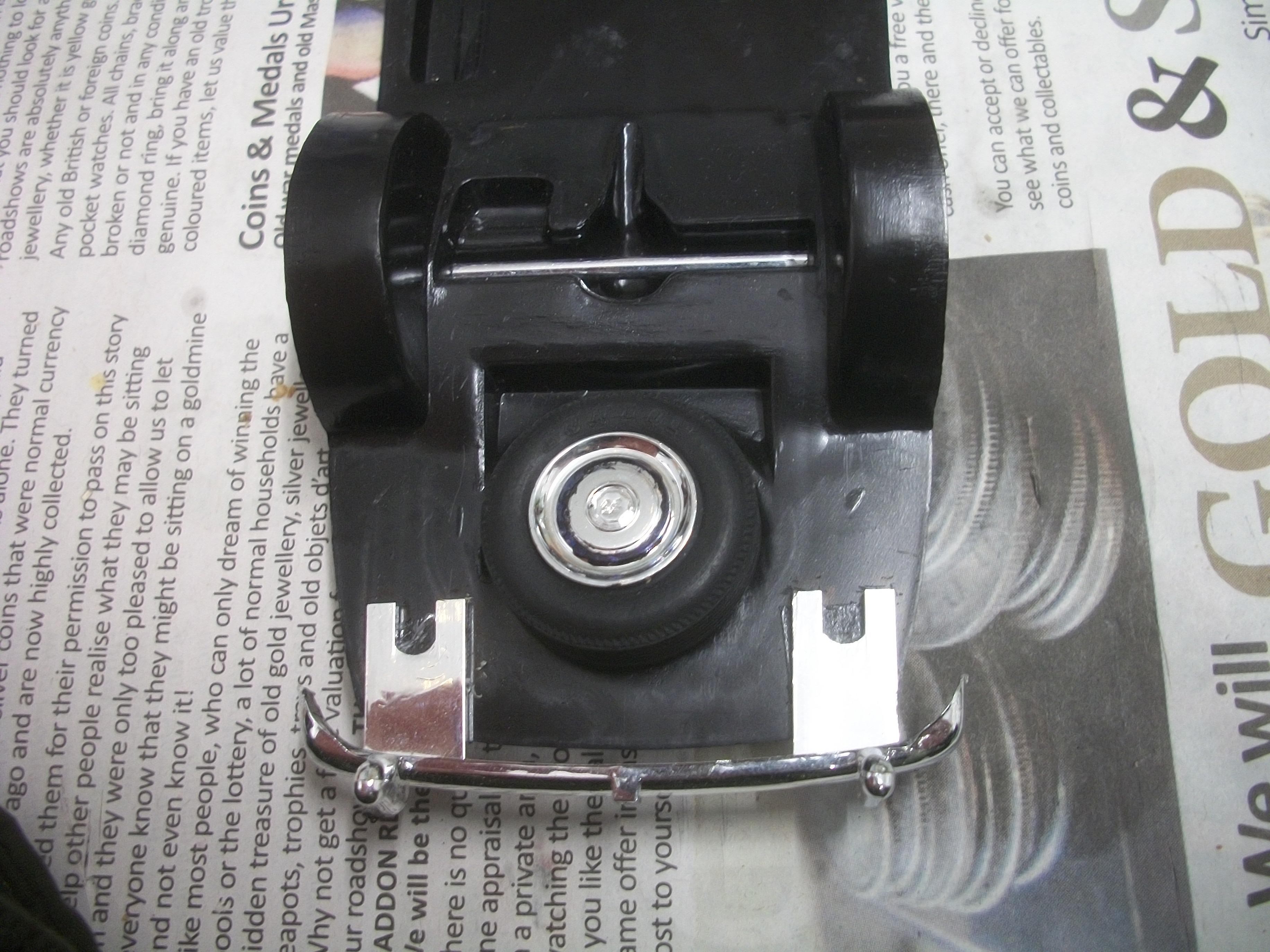
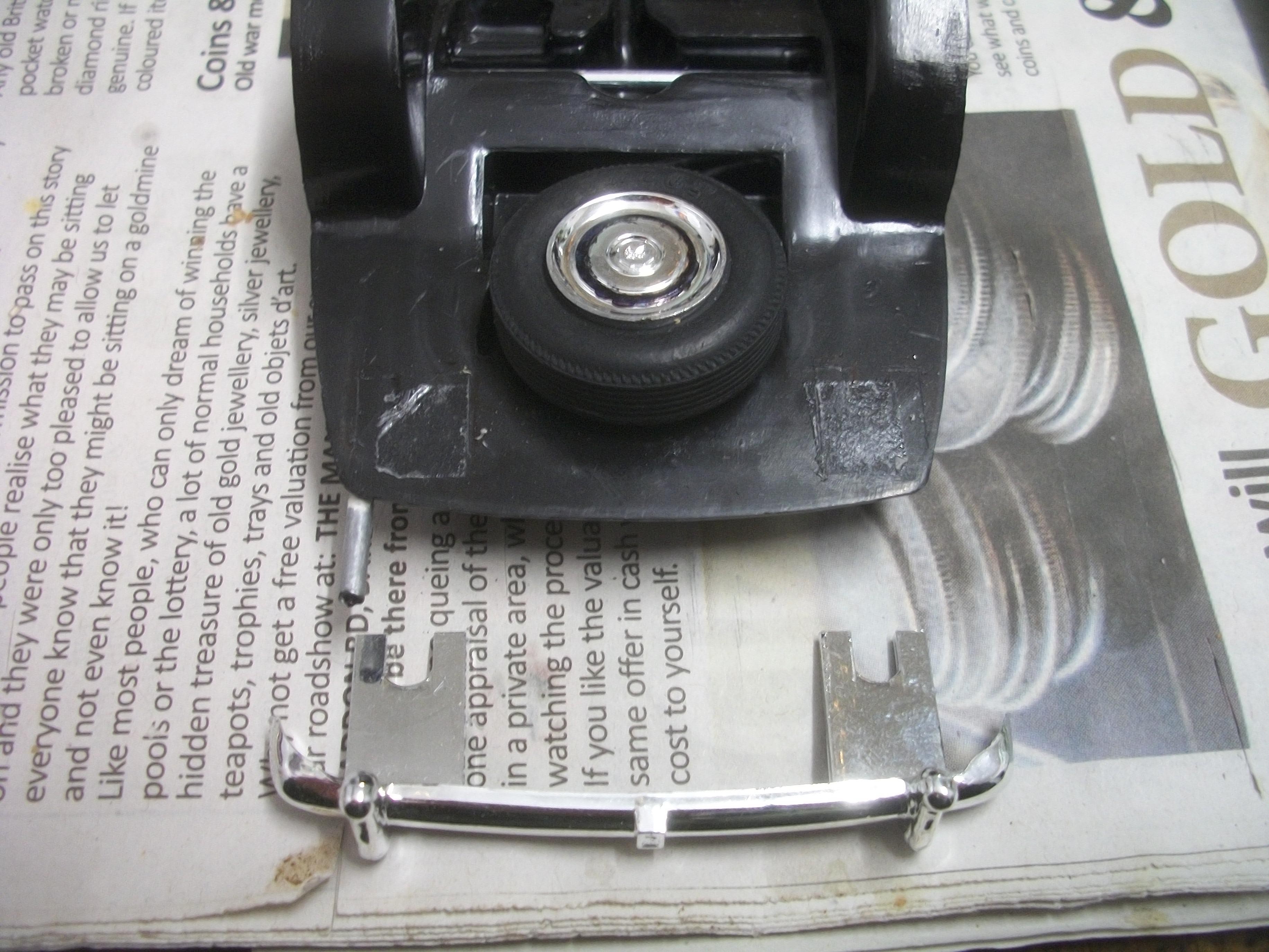
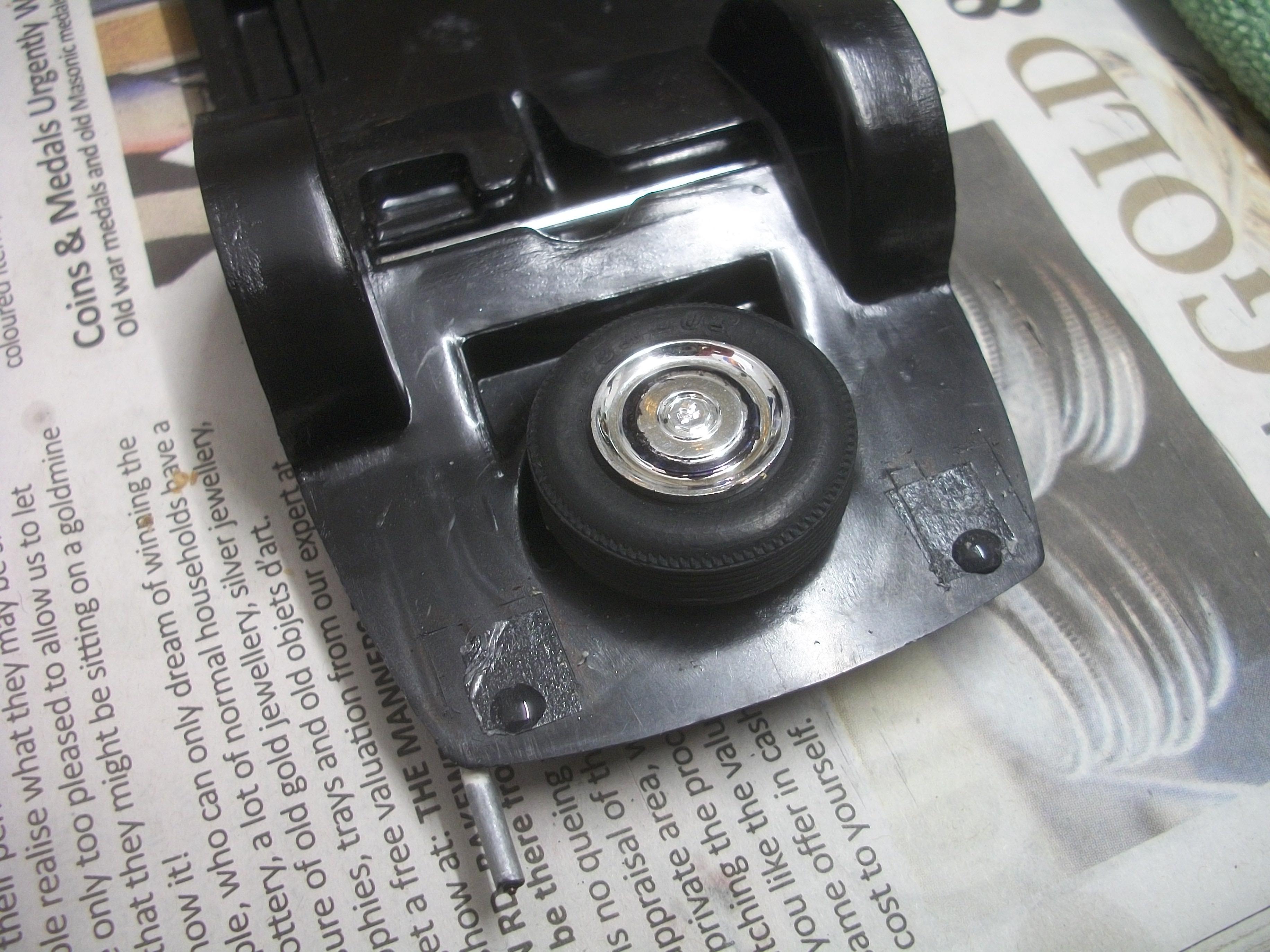
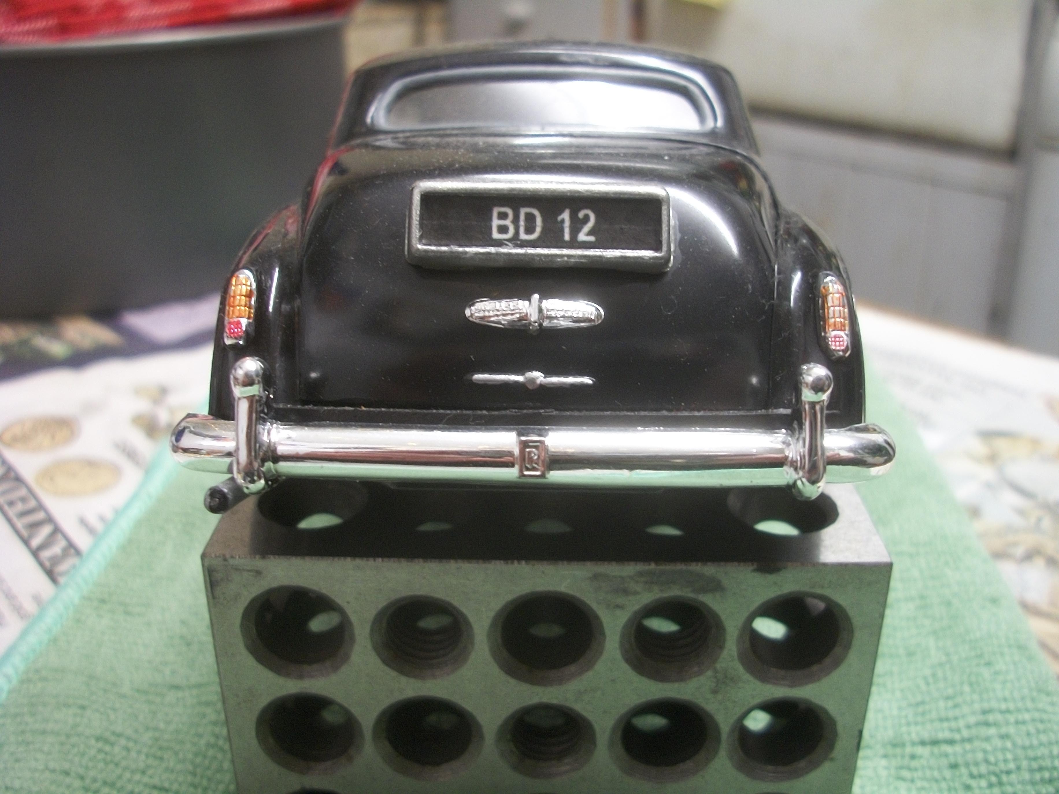
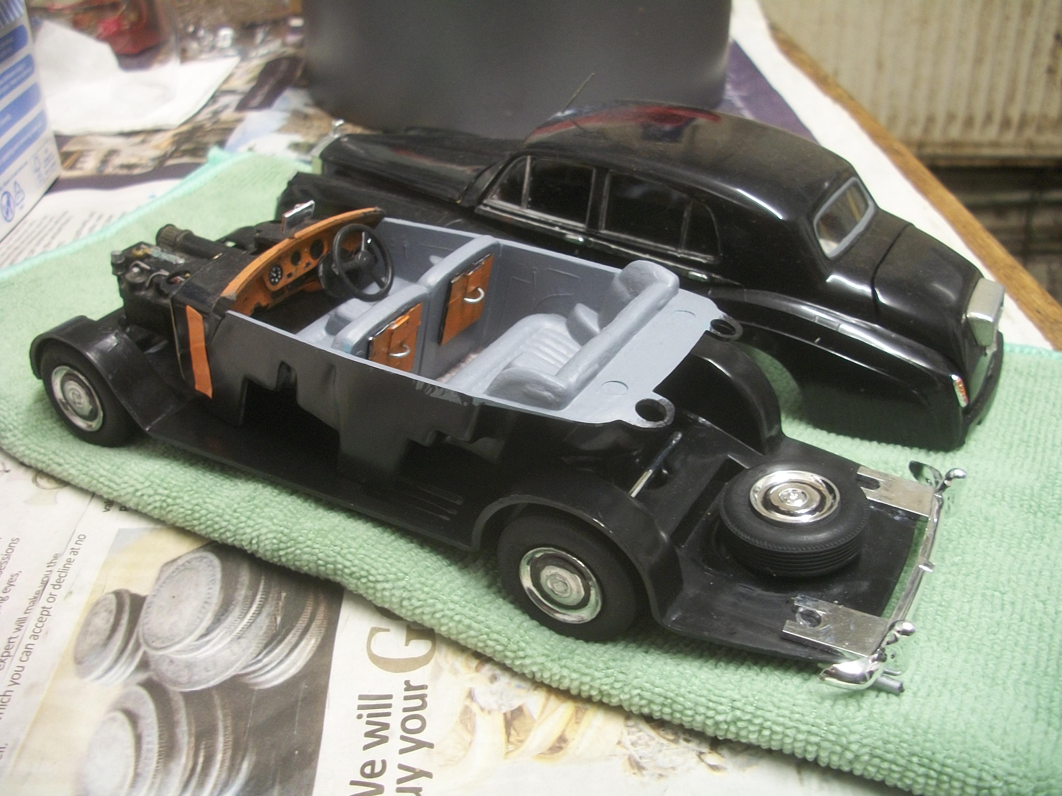
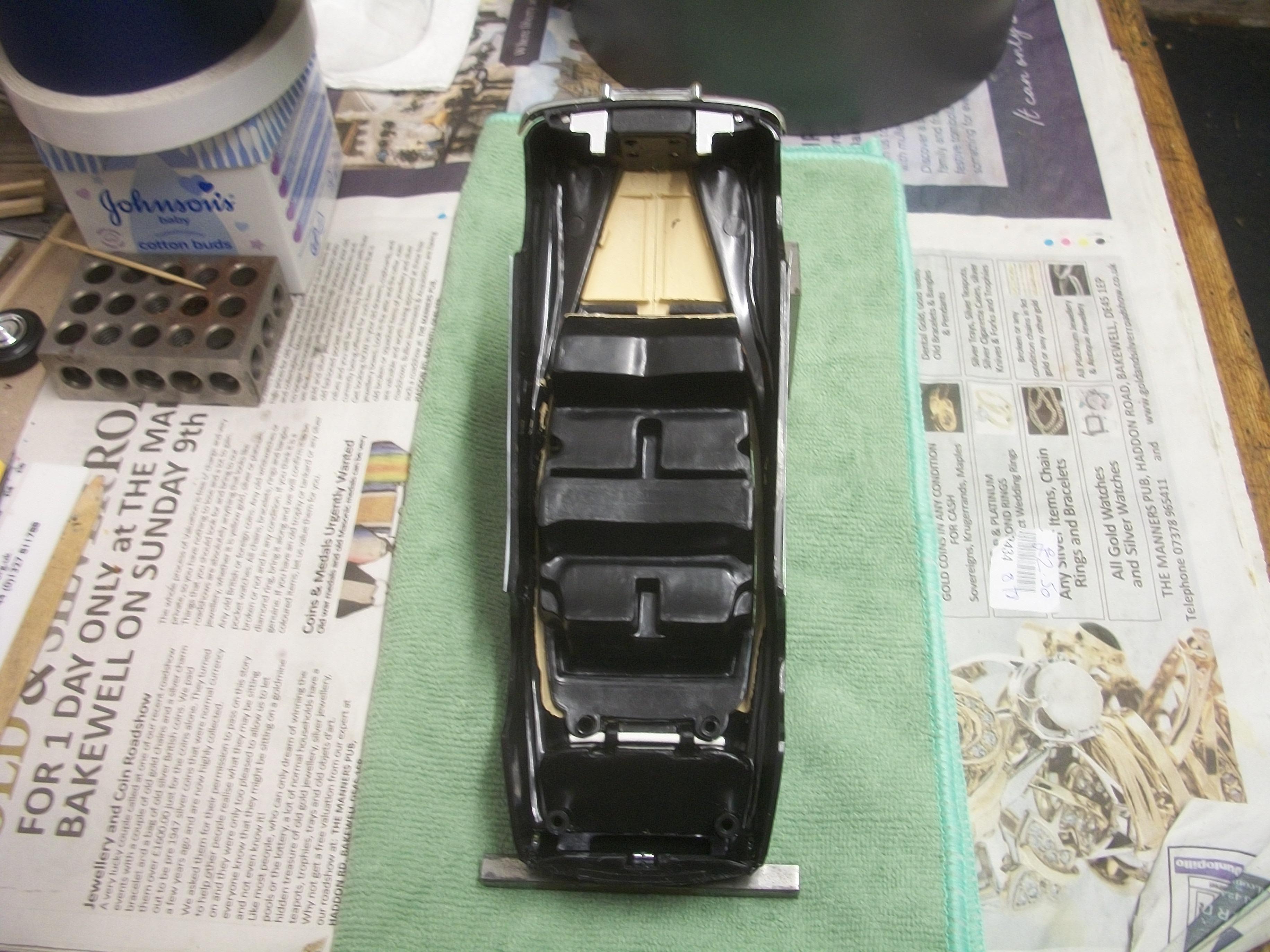
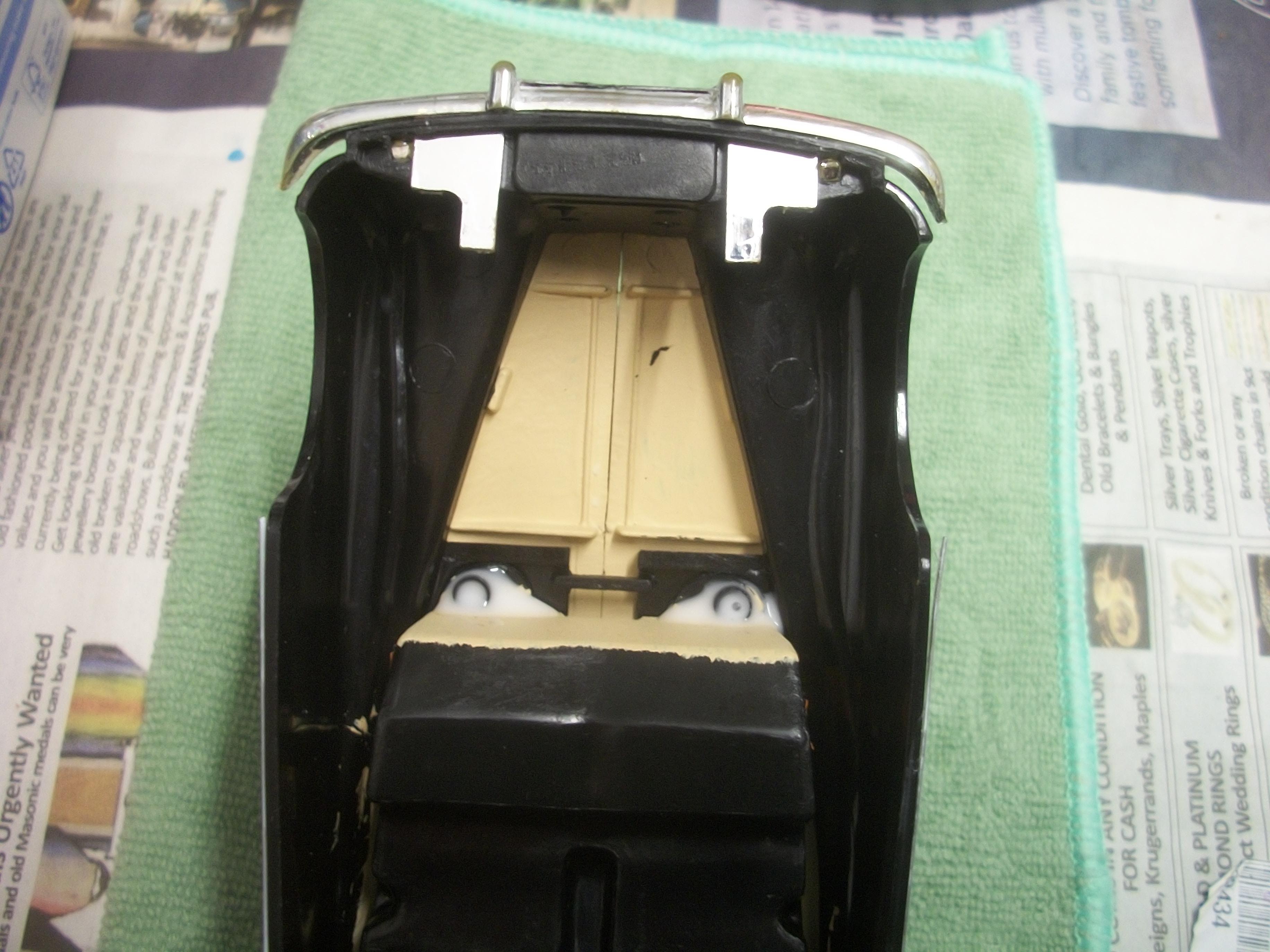
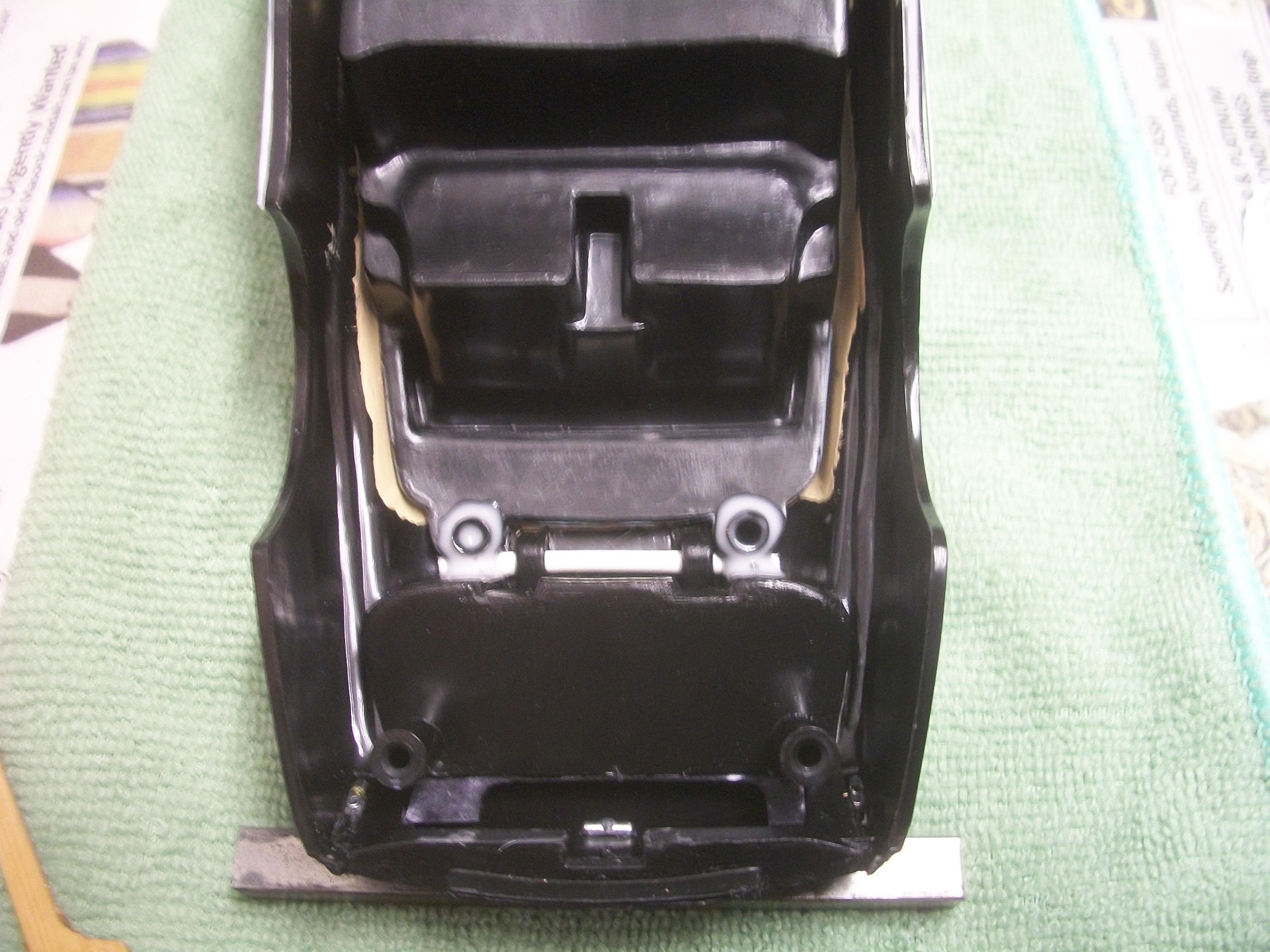
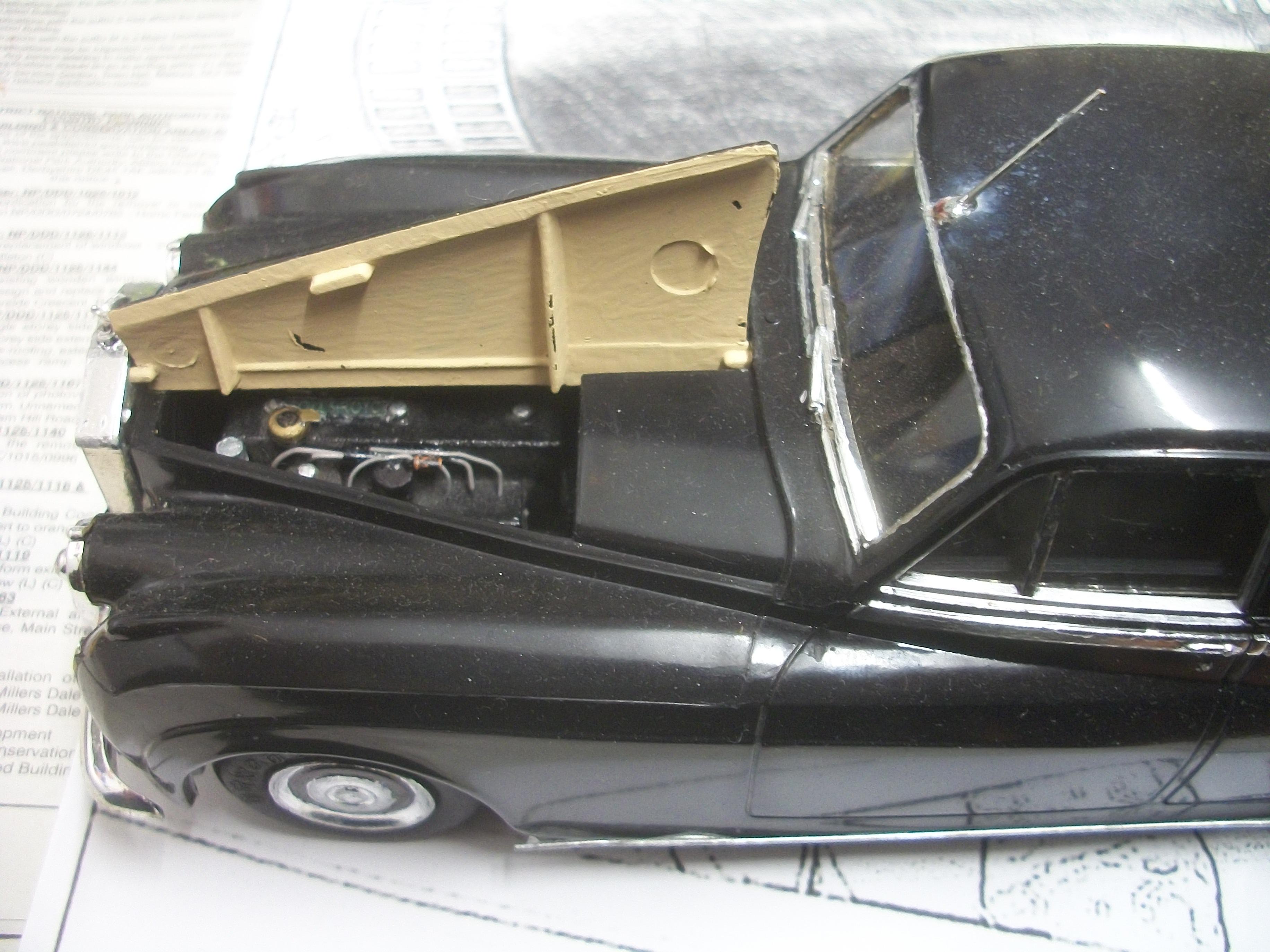
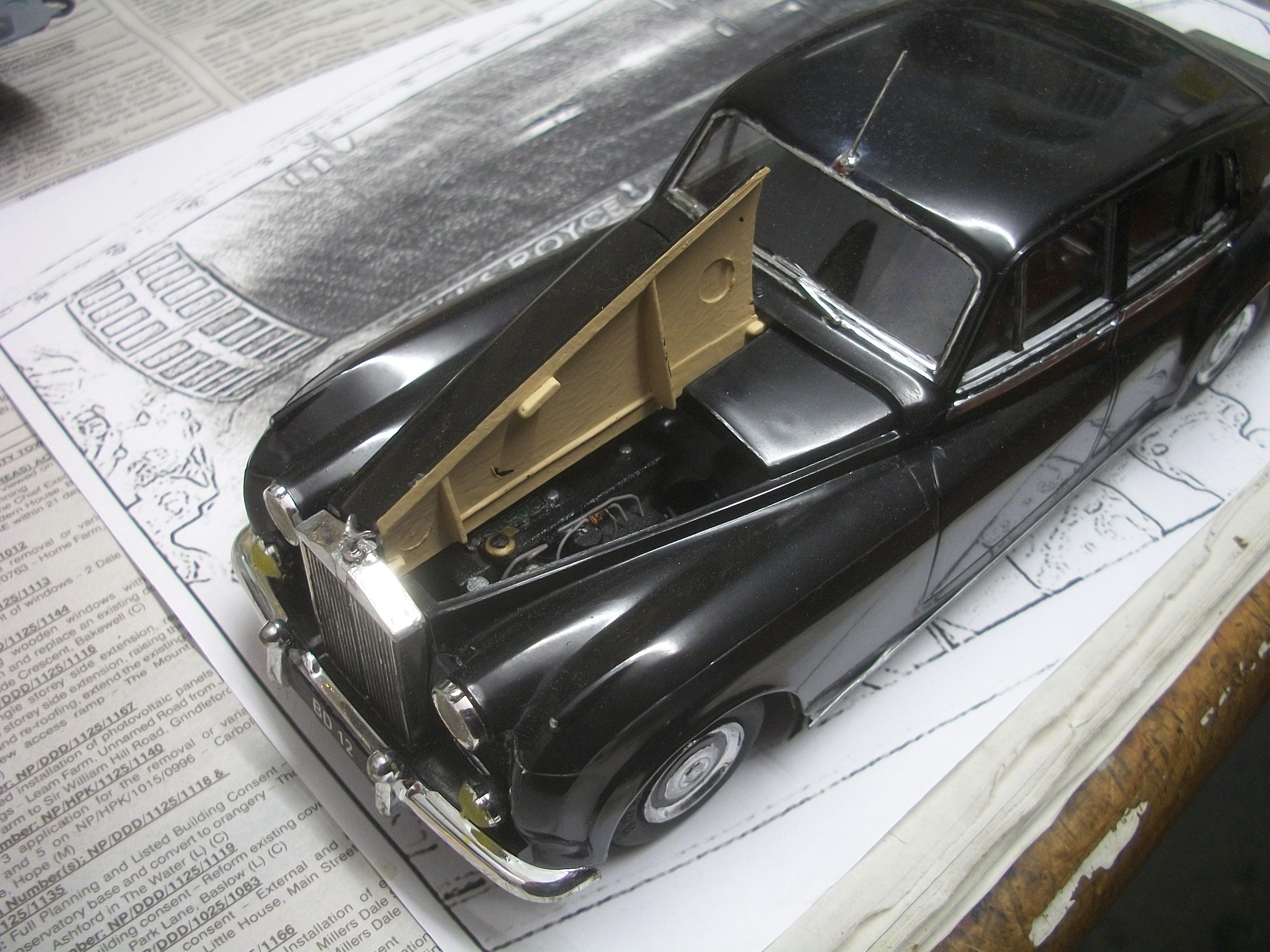
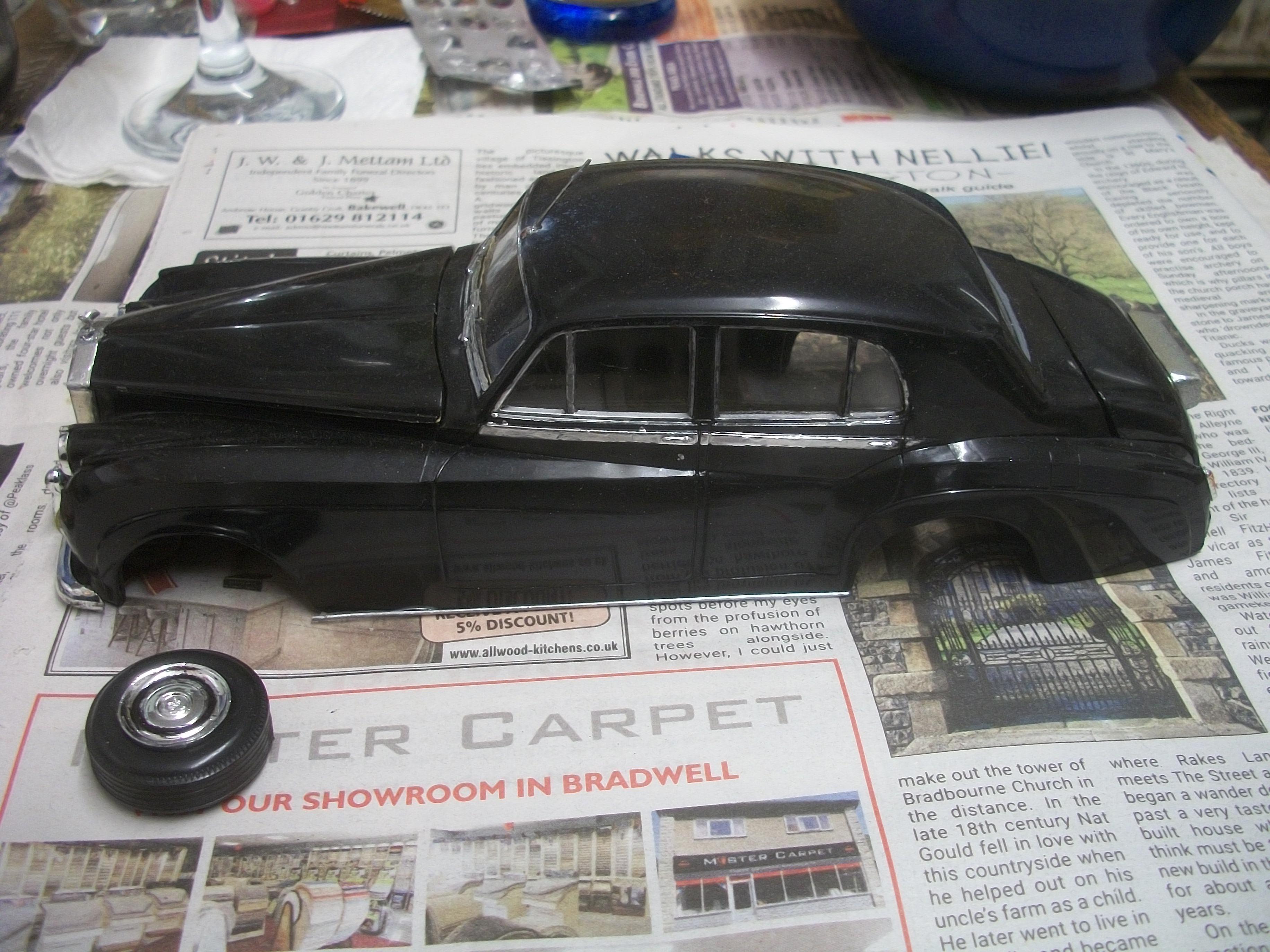
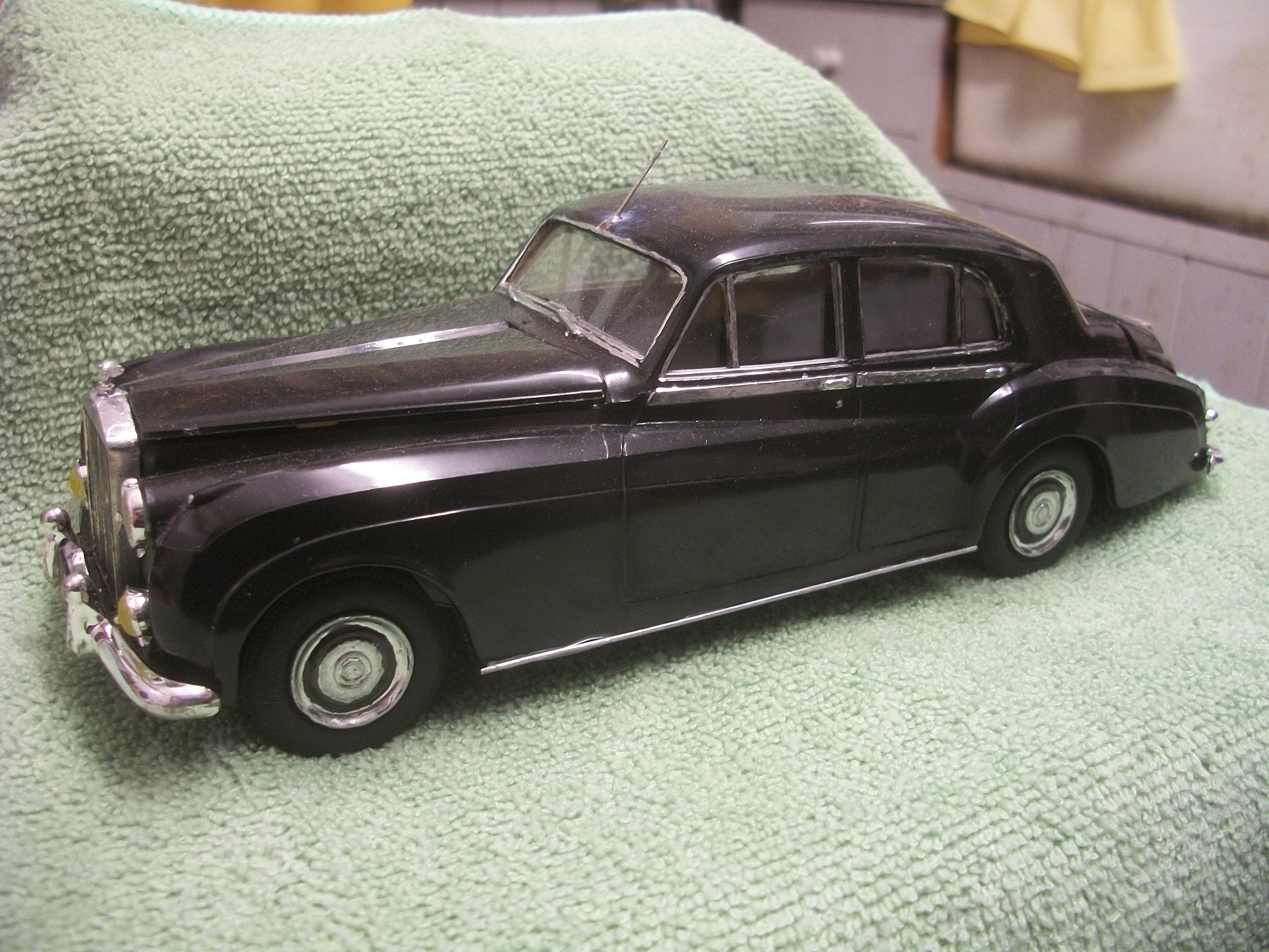
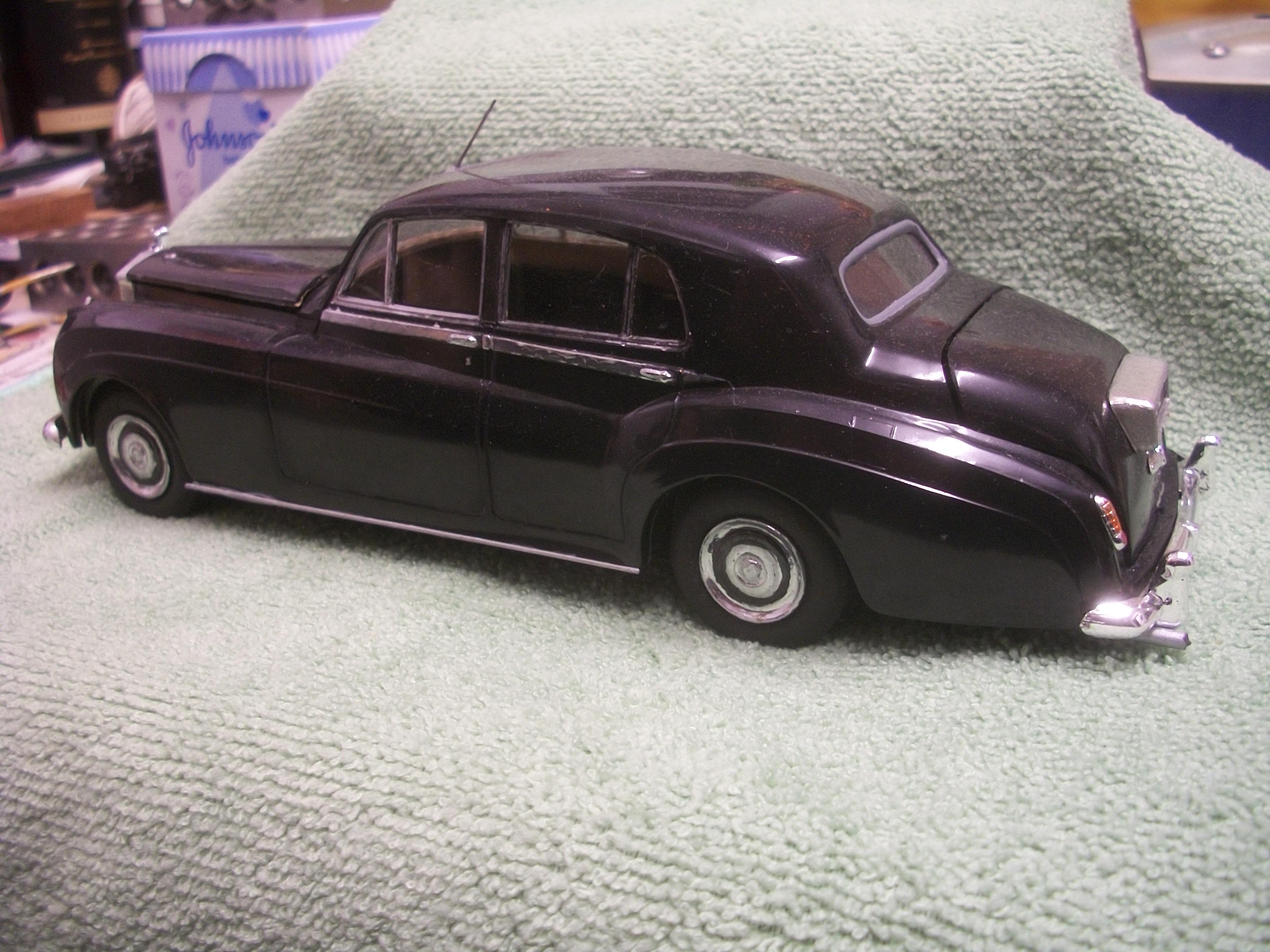
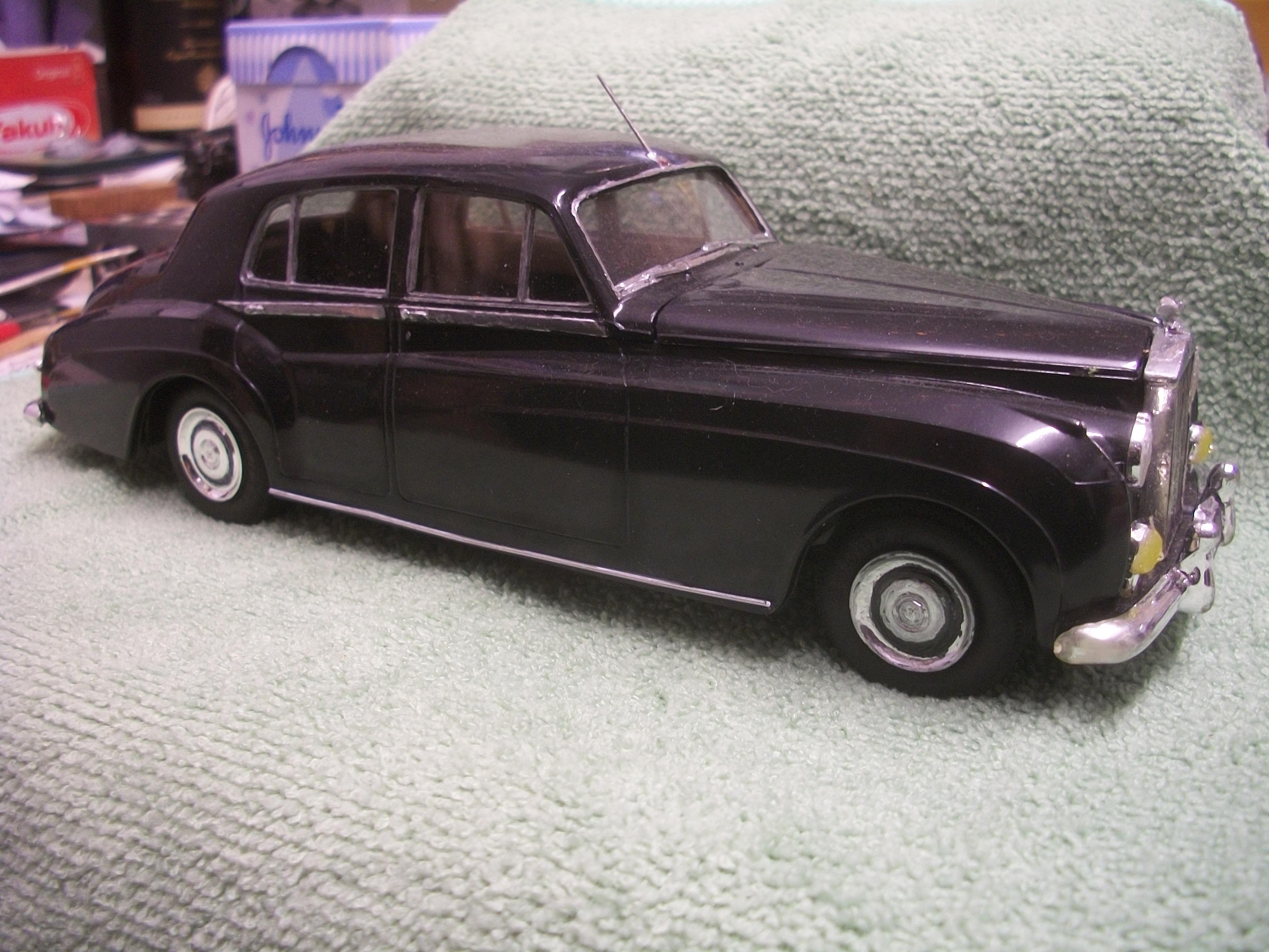
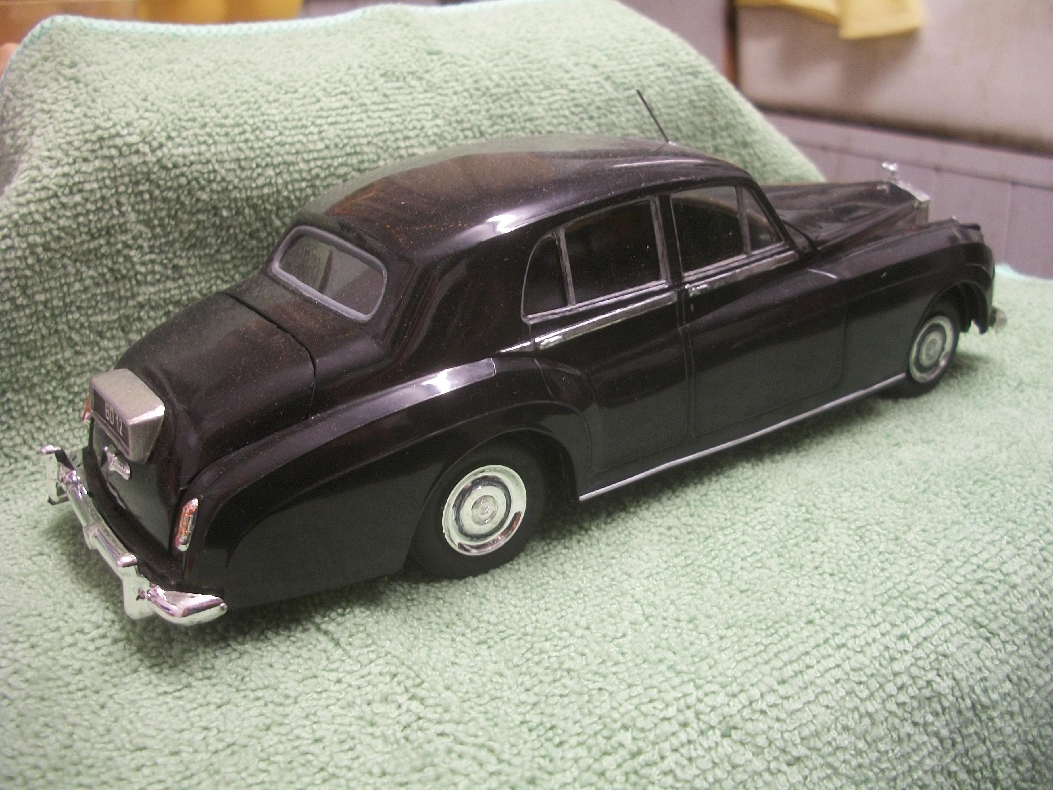
I managed to get two aspects of the build completed this evening . . . The rear bumper has been held in place on the chassis by double sided tape, purely as a temporary measure until it could be positioned correctly before glue was applied. Now the bumper is super glued in place, using two tiny dots of the offensive adhesive ! Then I moved onto the interior tub, which has been clipped onto the four locating pegs, two at the front and two at the rear. I decided to apply some PVA glue around each locating peg and allow the glue to run down into the gaps using gravity to do the job. This should secure the interior tub to the body, while still allowing access to the interior later if required . . . The PVA will be given 24 hours to set fully overnight. During the work on the interior tub the body was supported in such a way as to protect both the roof antenna, and also the Spirit of Ecstasy hood mascot. David
-
Excellent result Mark, and a fascinating story of the actual race that Mario Andretti won that day . . . Your home made decals could easily pass for boxed manufactured decals, and they were well worth the hard work that you clearly put in. You had to make several difficult decisions along the way during this build, such as the engine, the closed hood and the front suspension. All good in the end ! David J. Watson
-
Some tricky work going on there with mounting the wheels Mark, and I can see that you have done your absolute best with the paint polishing. Old decals can be a really difficult challenge to apply effectively . . . This model will display nicely when it's done I'm sure. I do like the blue and the gold together. David W.
-
Rolls-Royce No Chemicals, No Paint, No Harmful Glues
Anglia105E replied to Anglia105E's topic in WIP: Model Cars
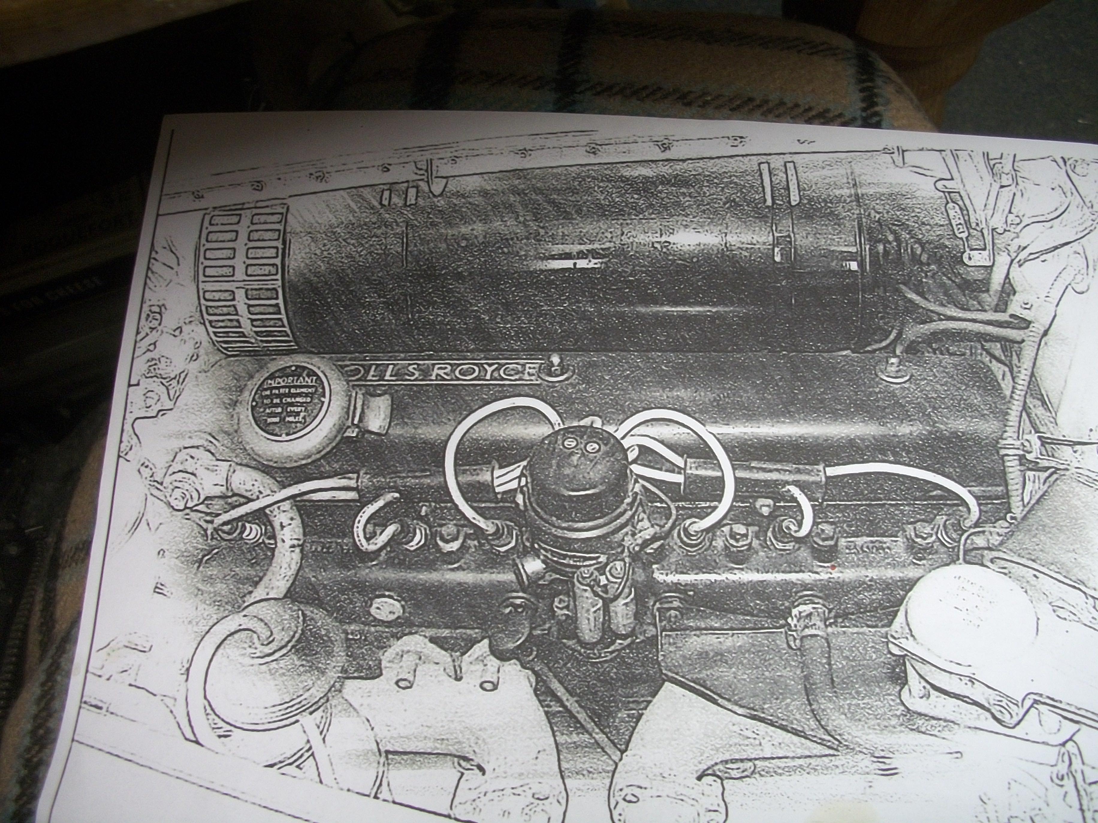
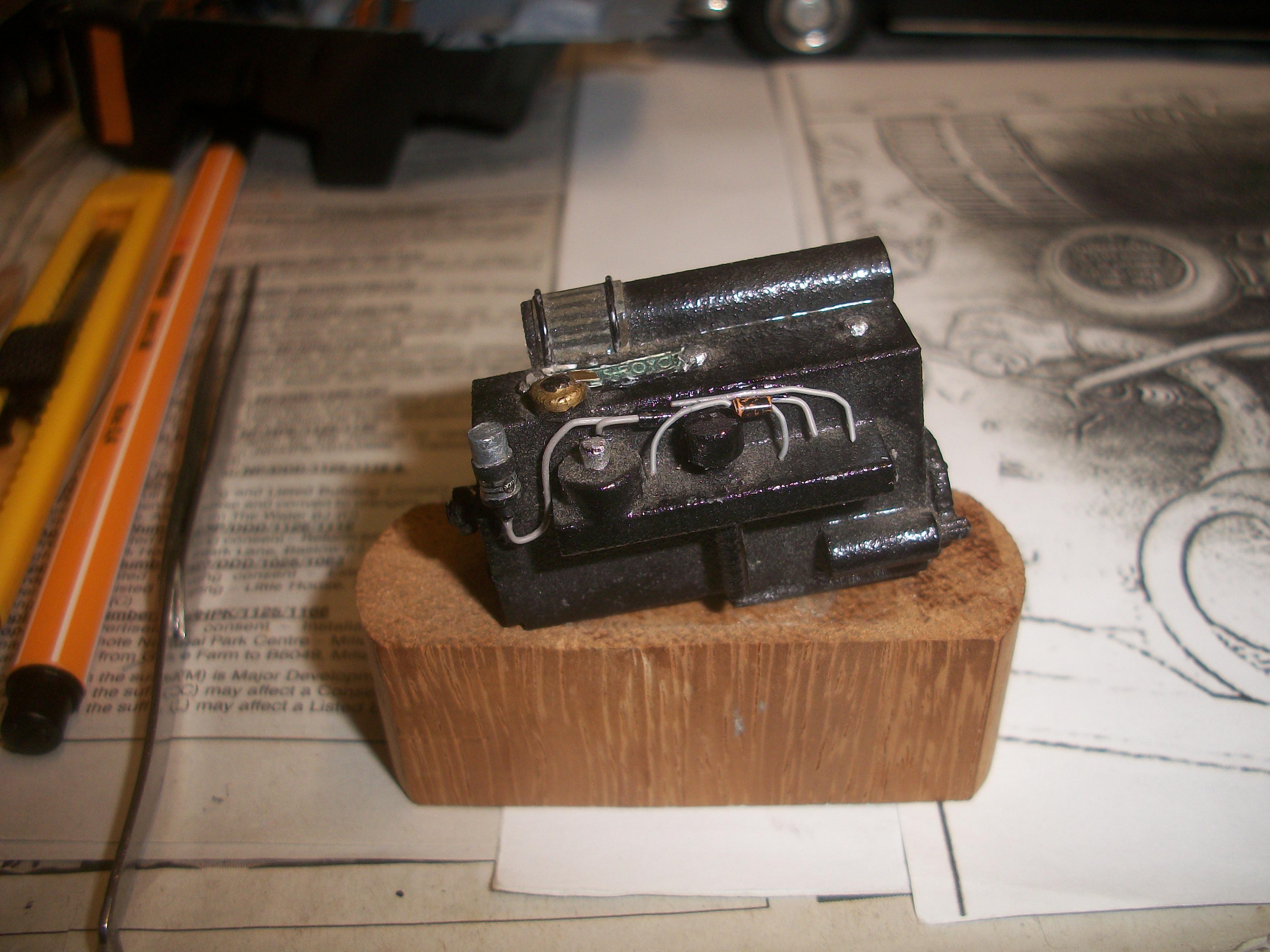
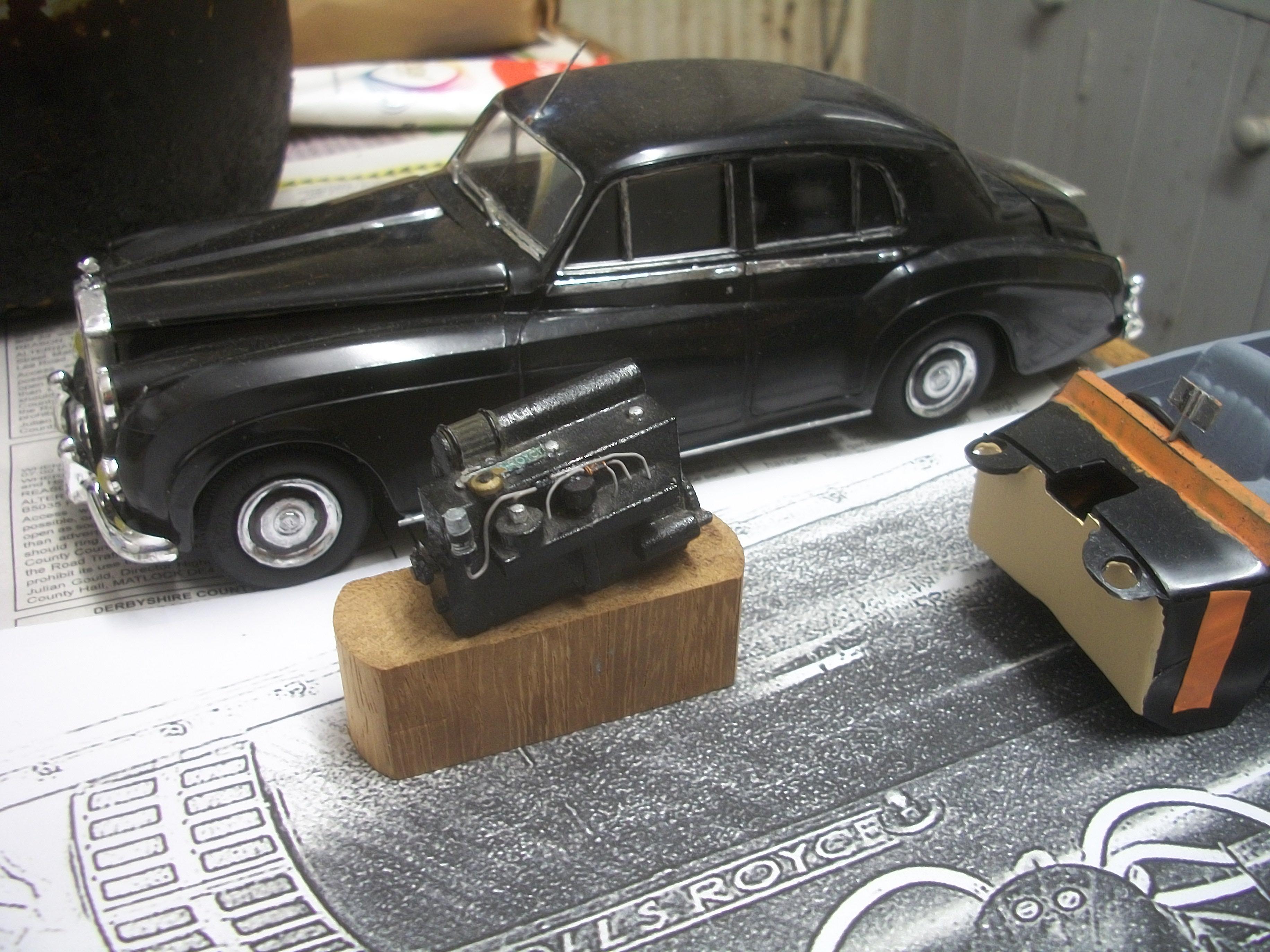
This evening I was able to get a little more engine detail done, and although not a great deal, I am slowly adding a few tiny components to the engine. Here are a few photos of the engine test fitted in the engine bay of the car . . . David
-
Rolls-Royce No Chemicals, No Paint, No Harmful Glues
Anglia105E replied to Anglia105E's topic in WIP: Model Cars
Thank you Mark . . . It was mainly as a result of useful suggestions by yourself and John Rourke and also Les Budge that brought me to this point. Without the use of the hollow punch set of hole cutters I would not have achieved this result effectively . . . This is why the MCM Forums are so important for us as model builders. David -
Rolls-Royce No Chemicals, No Paint, No Harmful Glues
Anglia105E replied to Anglia105E's topic in WIP: Model Cars
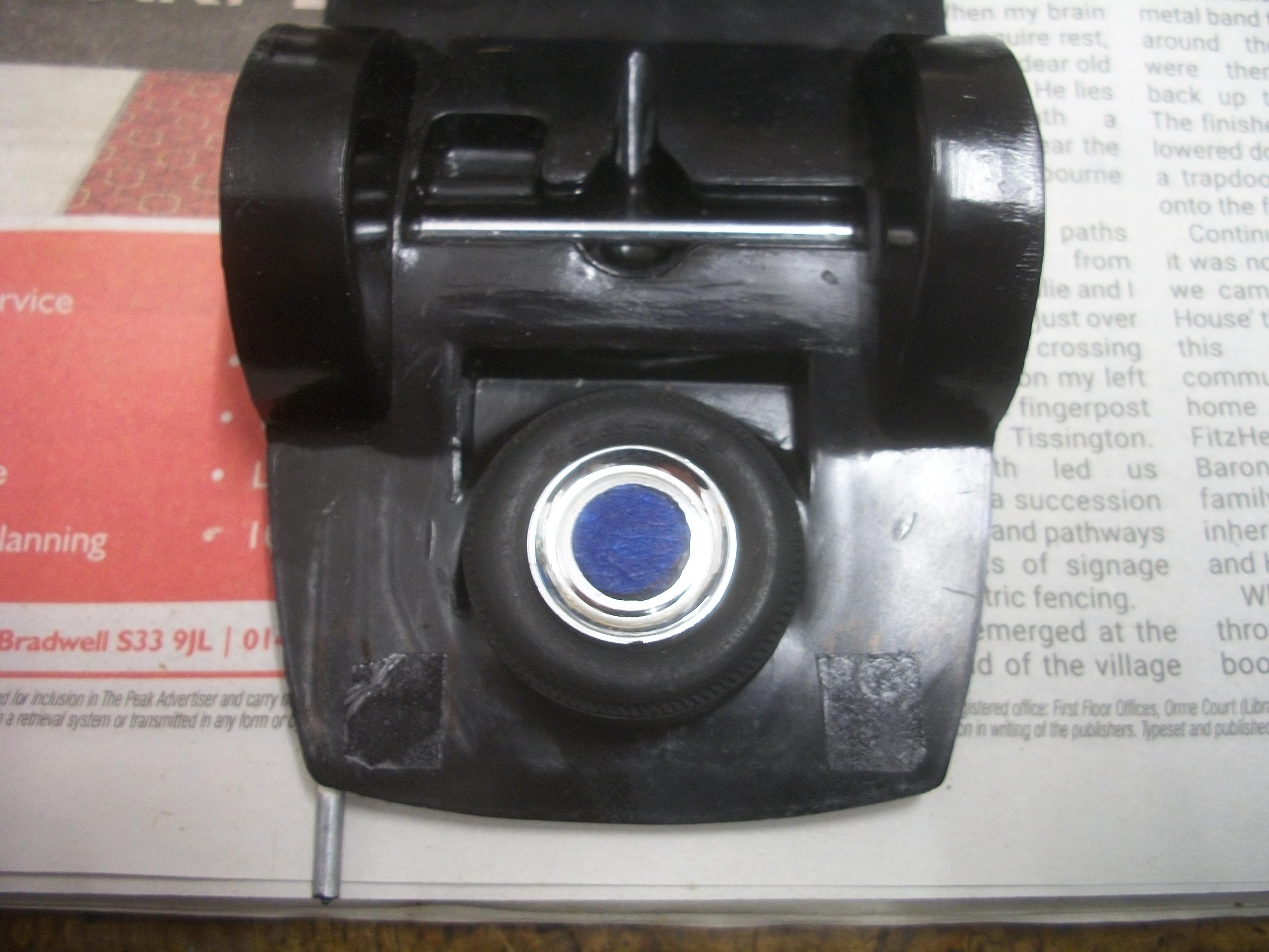
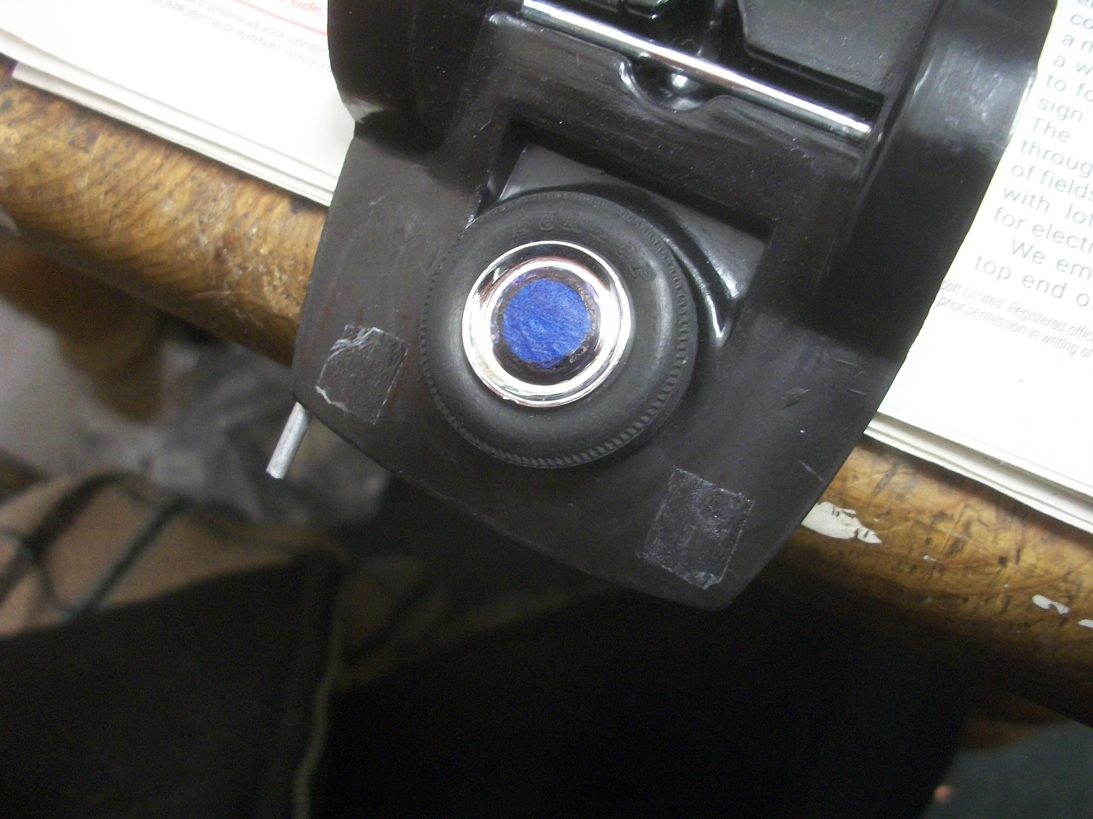
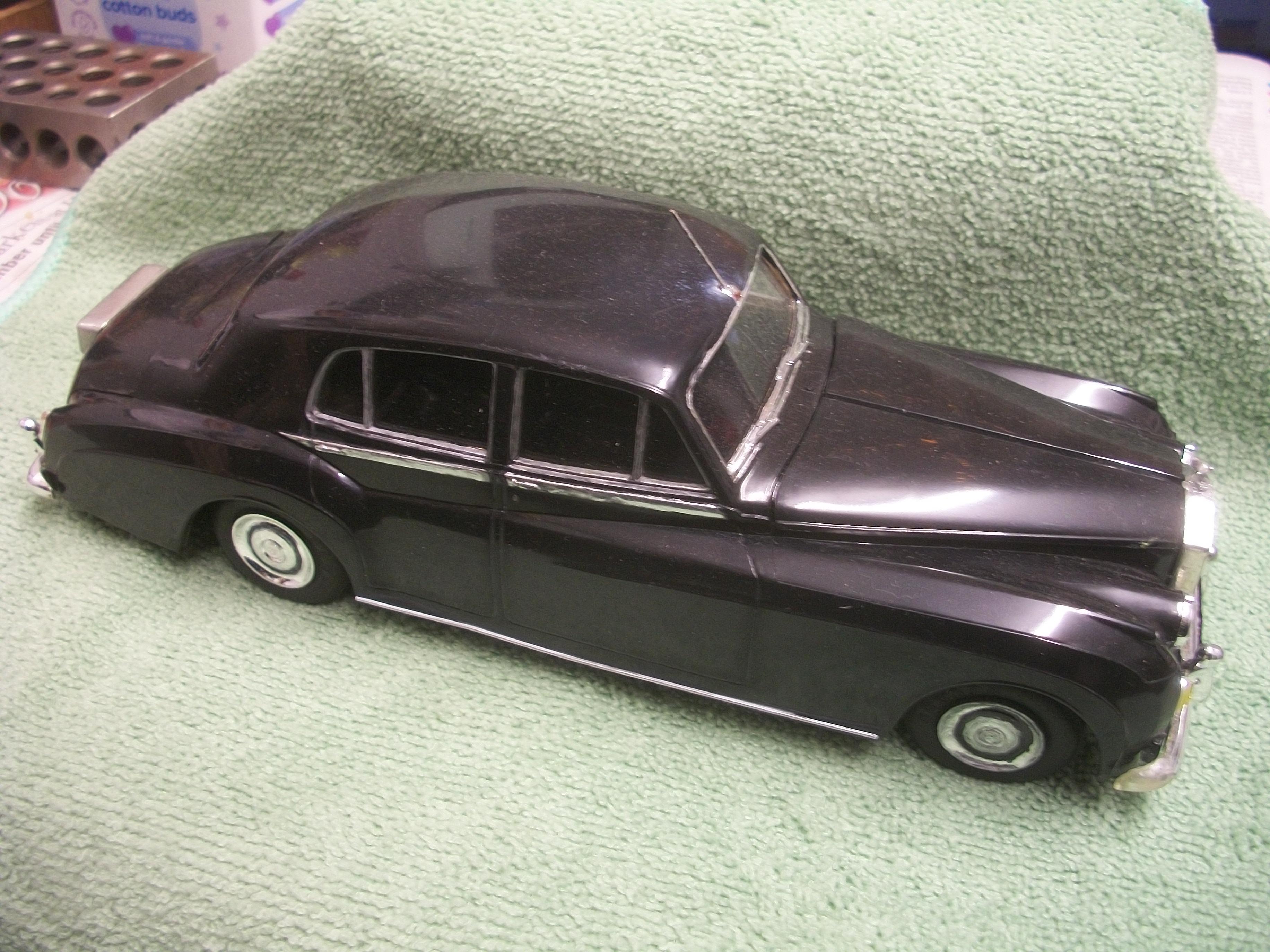
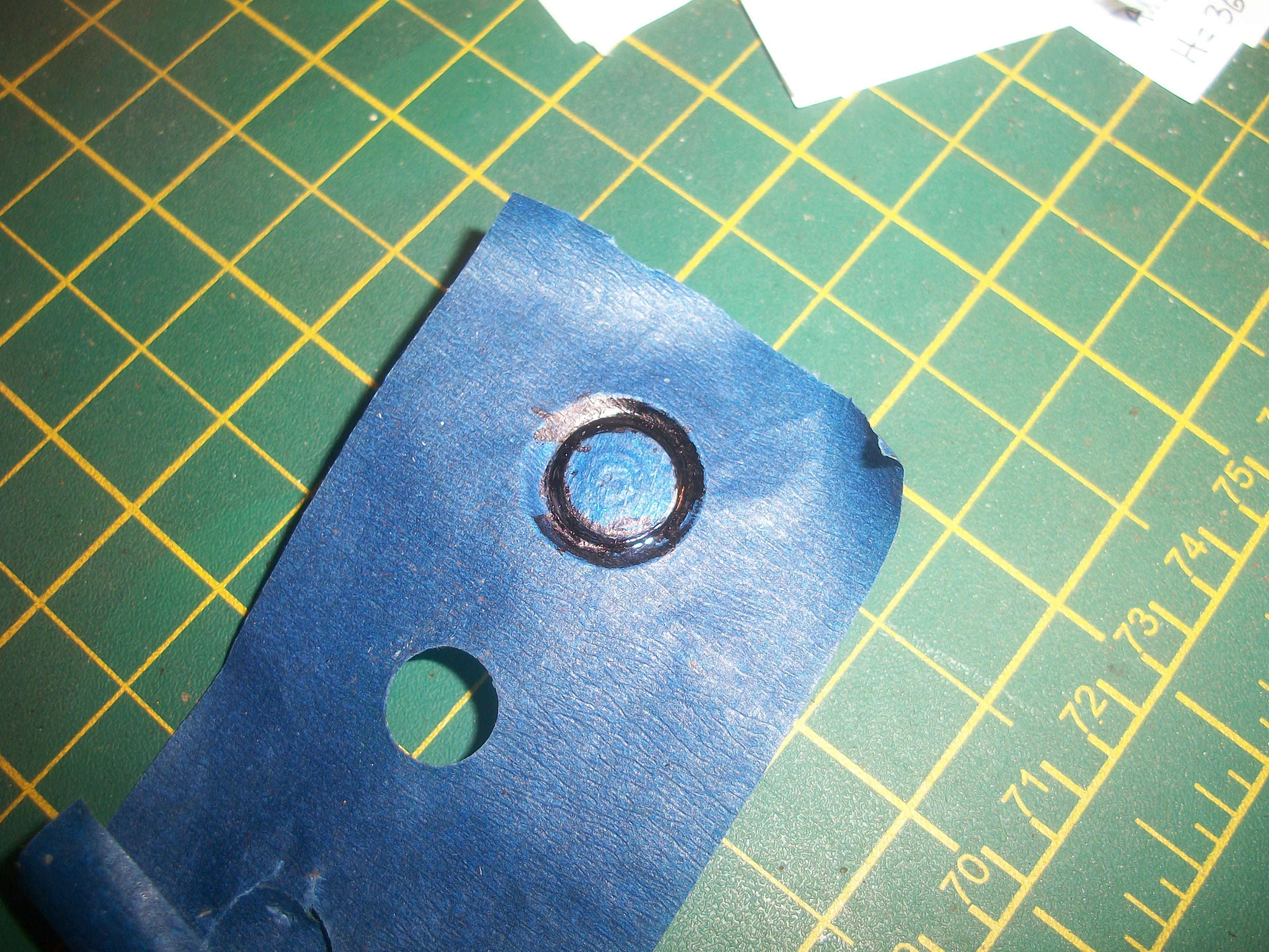
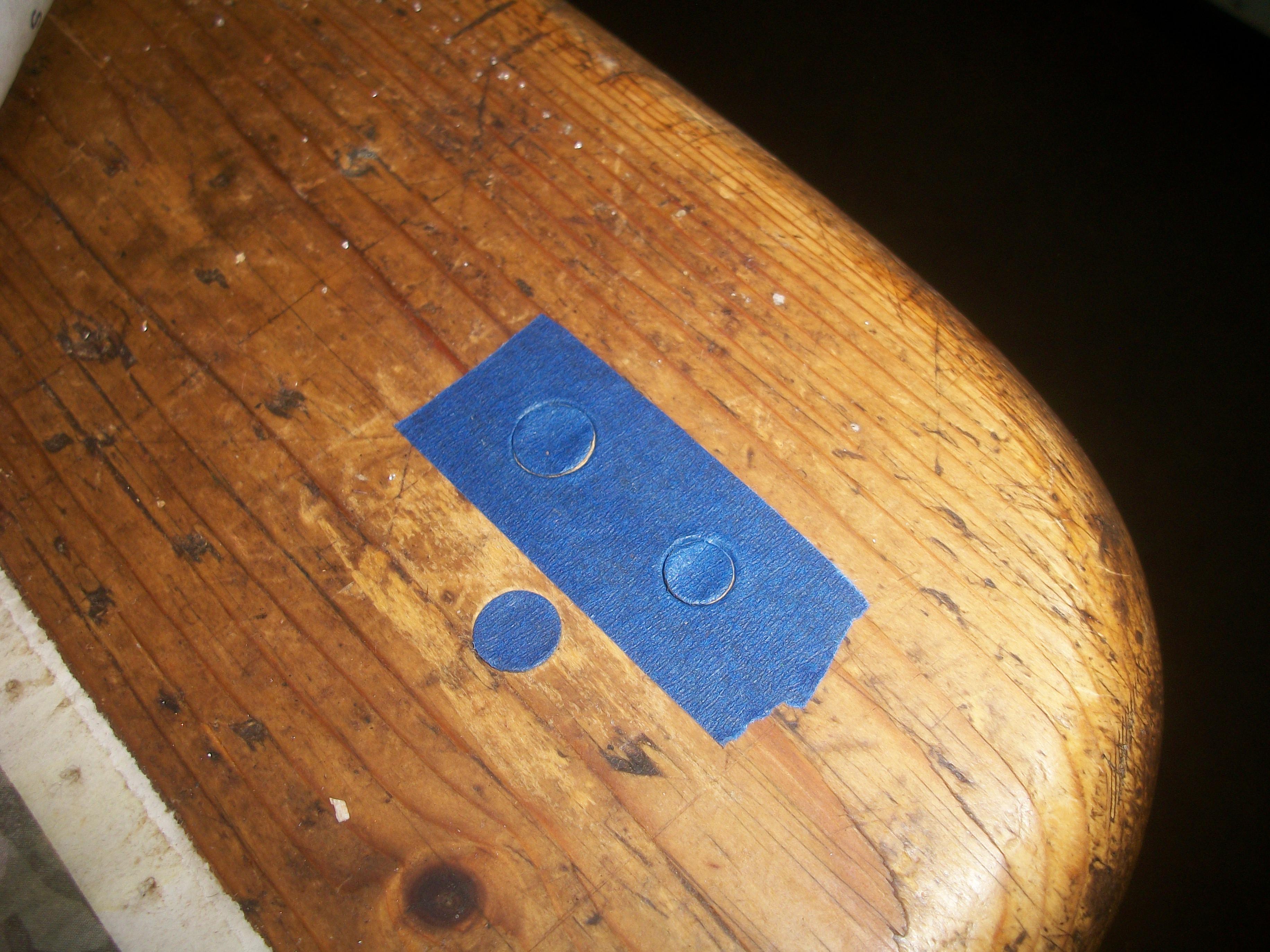
Having tried out the circles technique with a wheel that was not fitted to the car, I set about the four wheels on the axles, as well as the spare wheel. The two wheels on the passenger side were given a black circle, using the same pieces of masking tape that had been used for the testing. Then I cut out two new pieces of masking tape which came out good, and applied black circles to the two wheels on the driver's side. I decided to apply a black circle to the spare wheel also. Once all five wheels were done, I photographed the car with body on chassis to assess the result. Some liquid chrome does need to be applied in order to tidy up the circles, but only in very small amounts. David
-
Rolls Royce Silver Cloud II Drophead Coupe
Anglia105E replied to Perspect Scale Modelworks's topic in WIP: Model Cars
Good thinking Jose . . . It is surprising what can be done by arranging the bunch of parts ! David -
Rolls Royce Silver Cloud II Drophead Coupe
Anglia105E replied to Perspect Scale Modelworks's topic in WIP: Model Cars
I am finding your work on this Franklin Mint donor car very interesting, and all of this looks very familiar to me . . . One other part that caught my attention was the radiator grille shell, which is larger ( taller ) on the diecast model than it is on the styrene kit car versions . . . I agree with you, in that the engine and chassis underside parts are more nicely detailed than the plastic equivalents, so well worth using if you can. These Franklin Mint Rolls-Royce Silver Cloud model cars can be picked up sometimes on Ebay for reasonable prices, when they have parts missing or are in poor condition generally . . . It feels somehow wrong to be dismantling such a fine model motor car. but if it creates a whole new model like your drophead version, then I think this is justified at the end of the day. David W. -
Rolls-Royce No Chemicals, No Paint, No Harmful Glues
Anglia105E replied to Anglia105E's topic in WIP: Model Cars
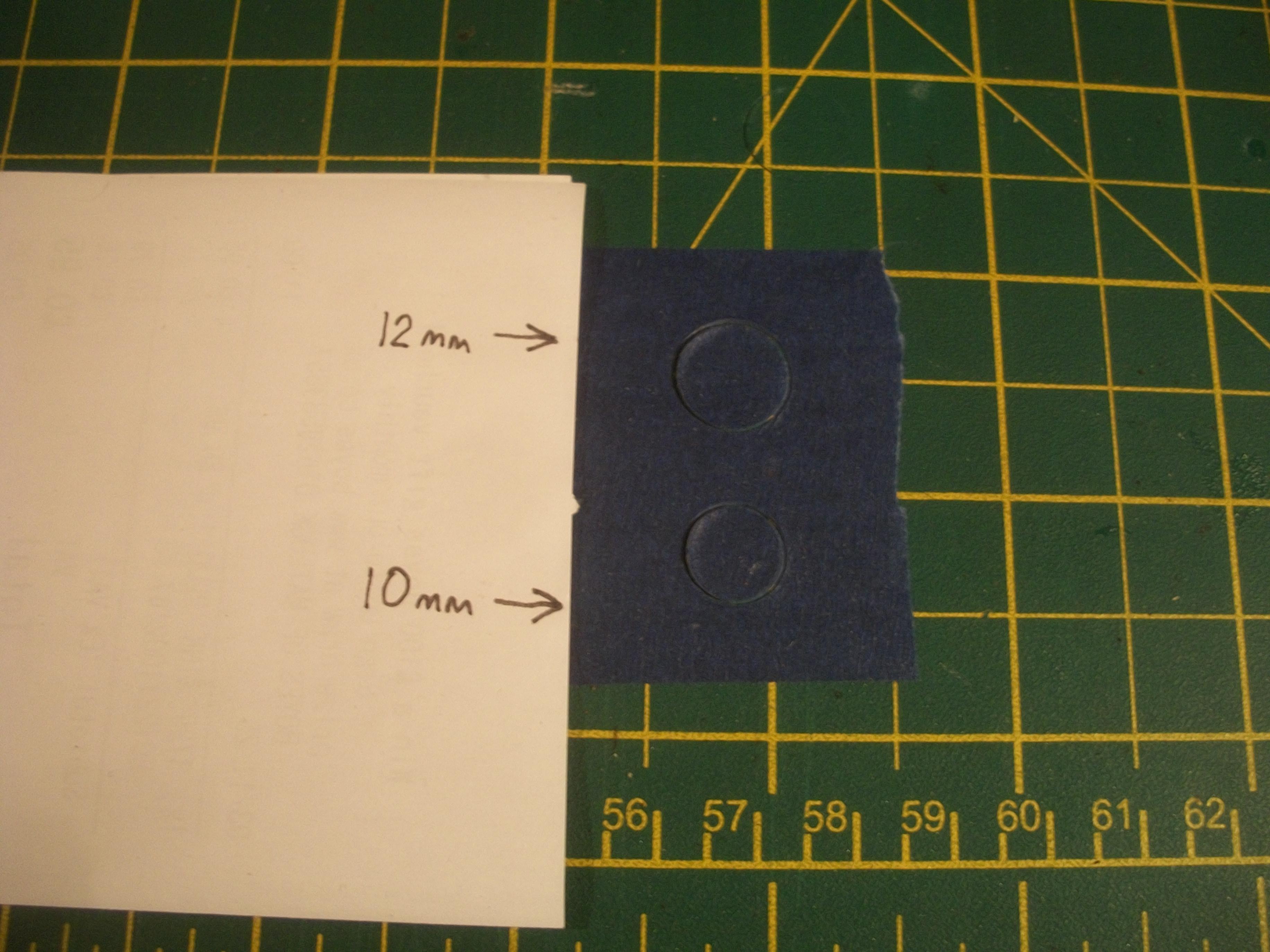
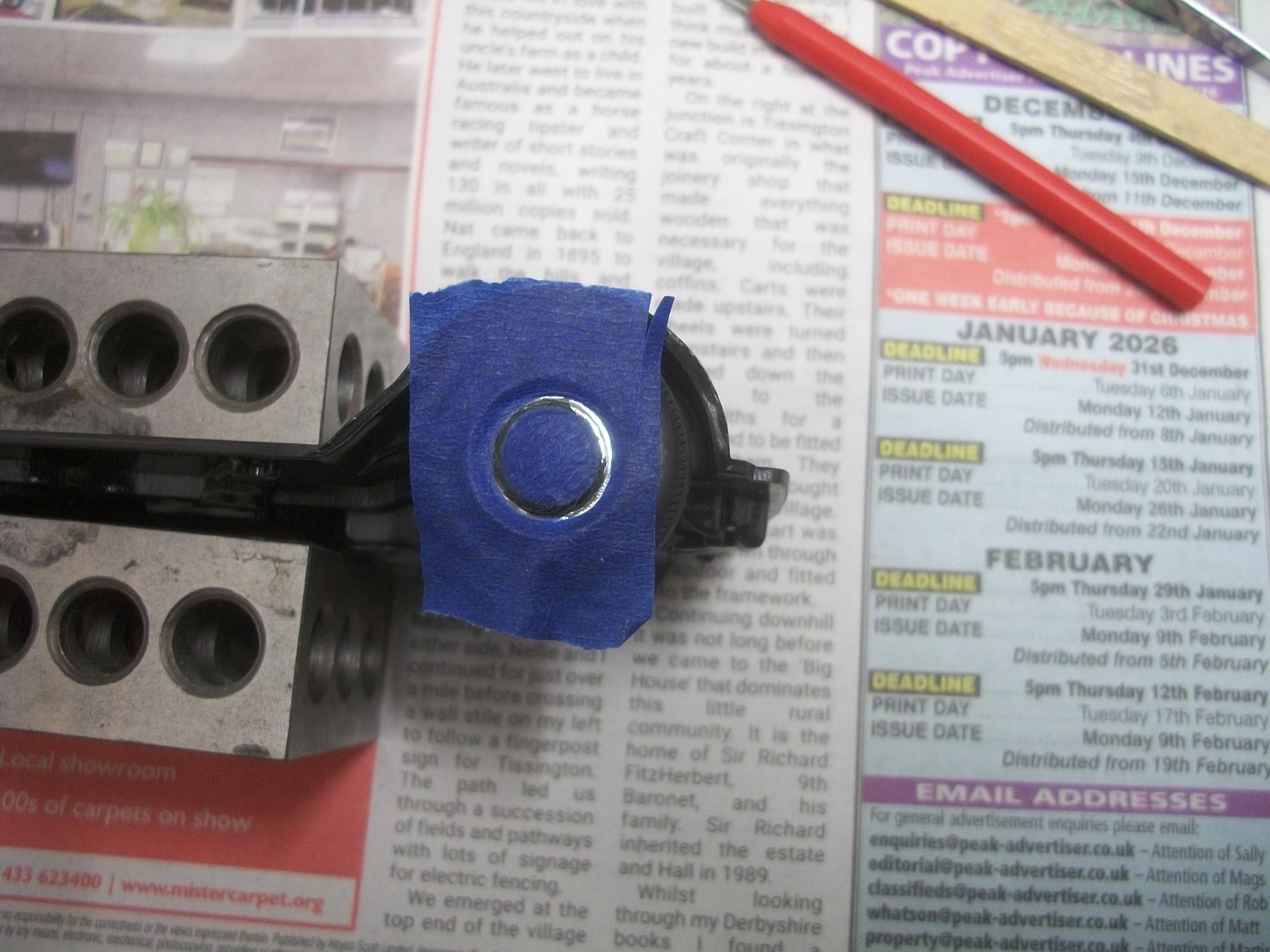
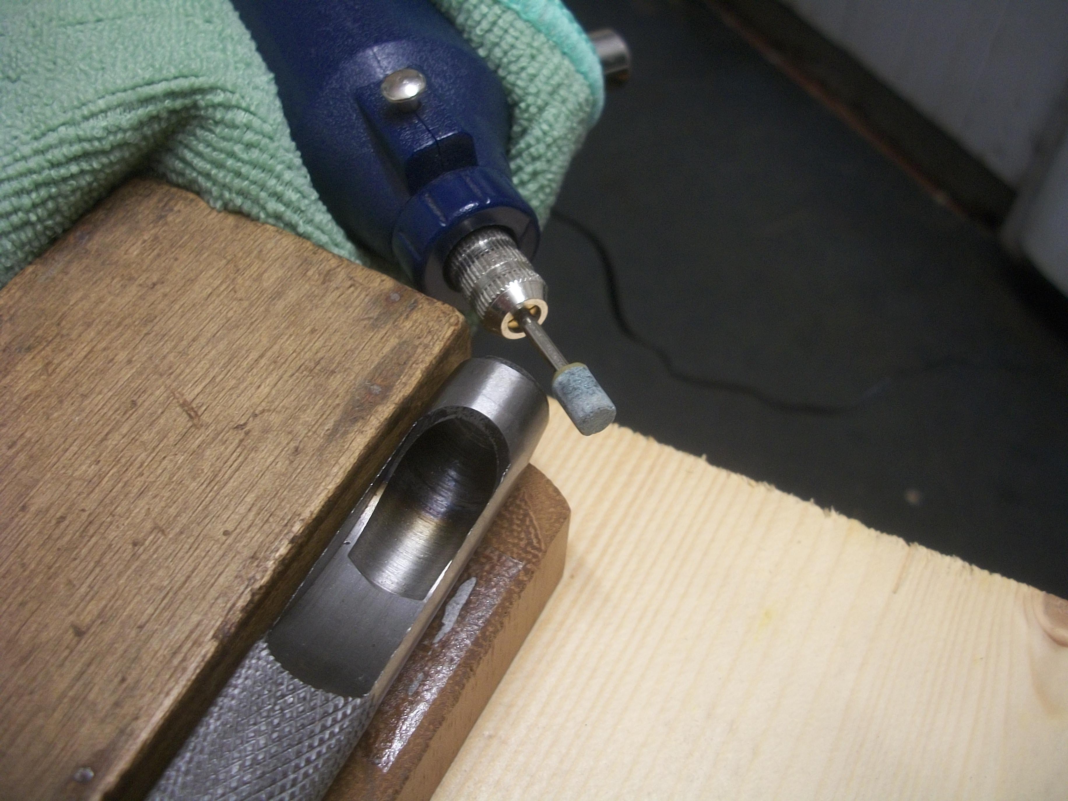
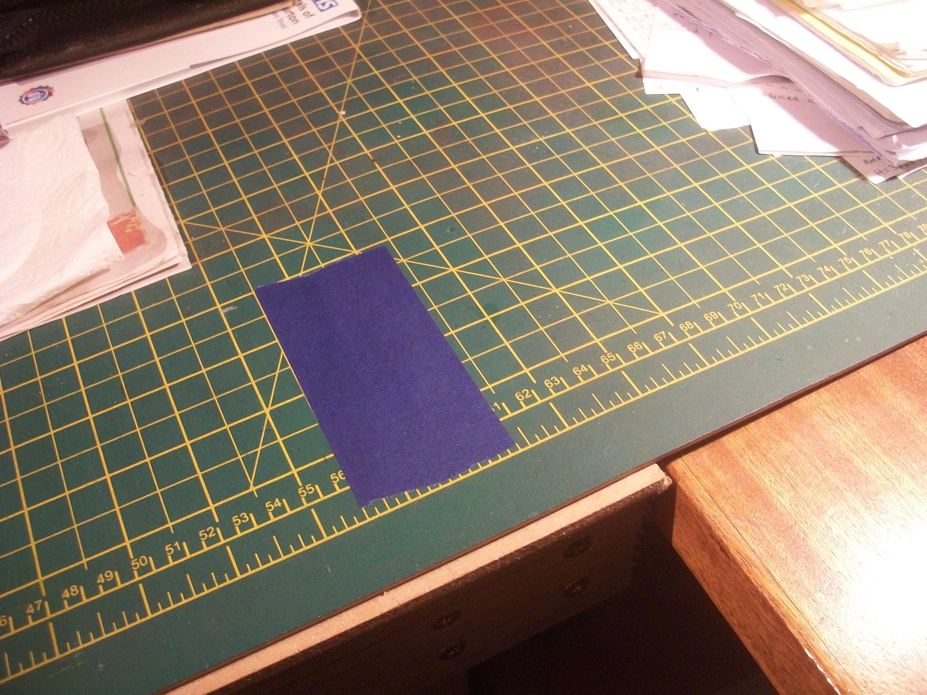
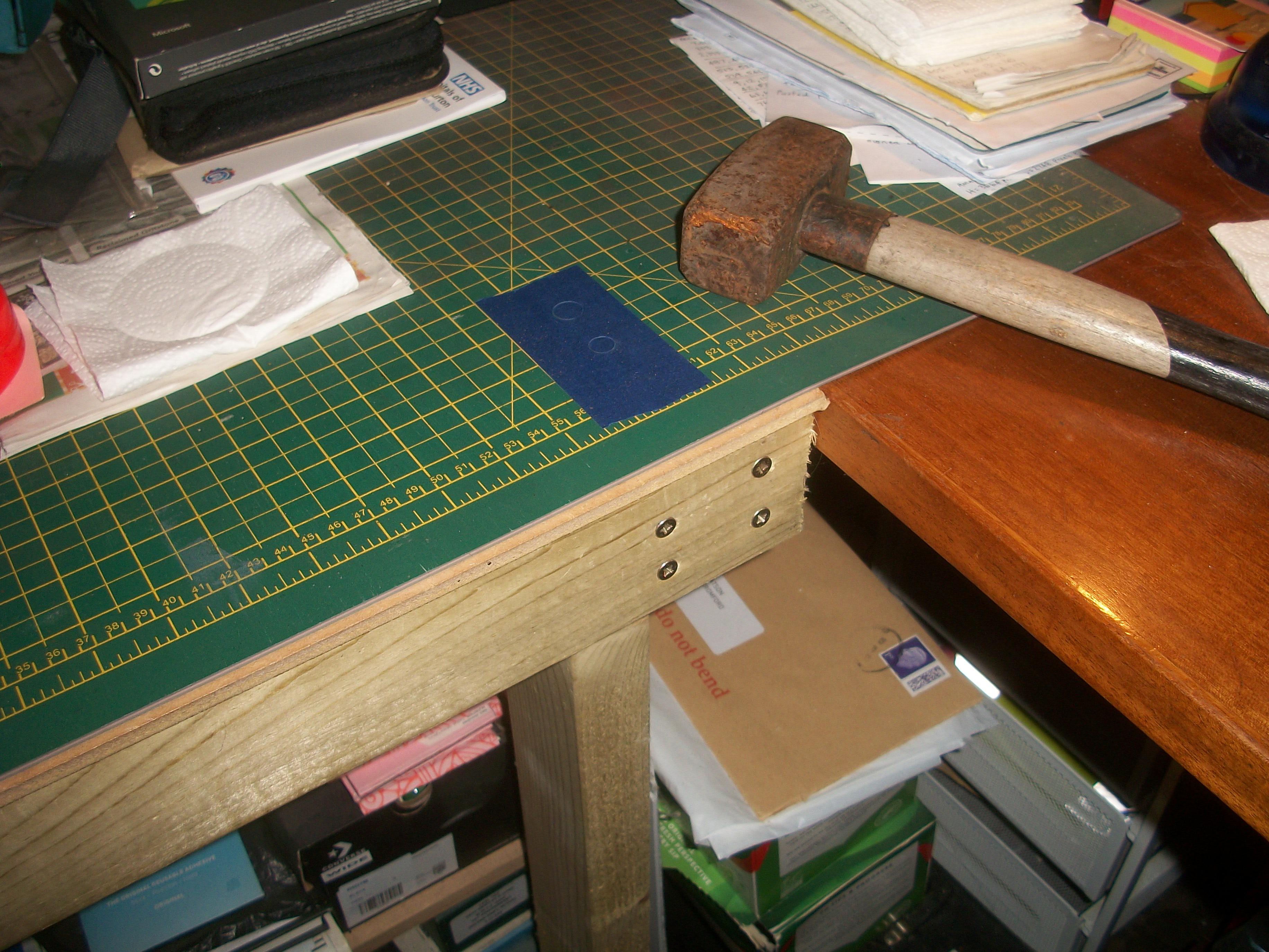
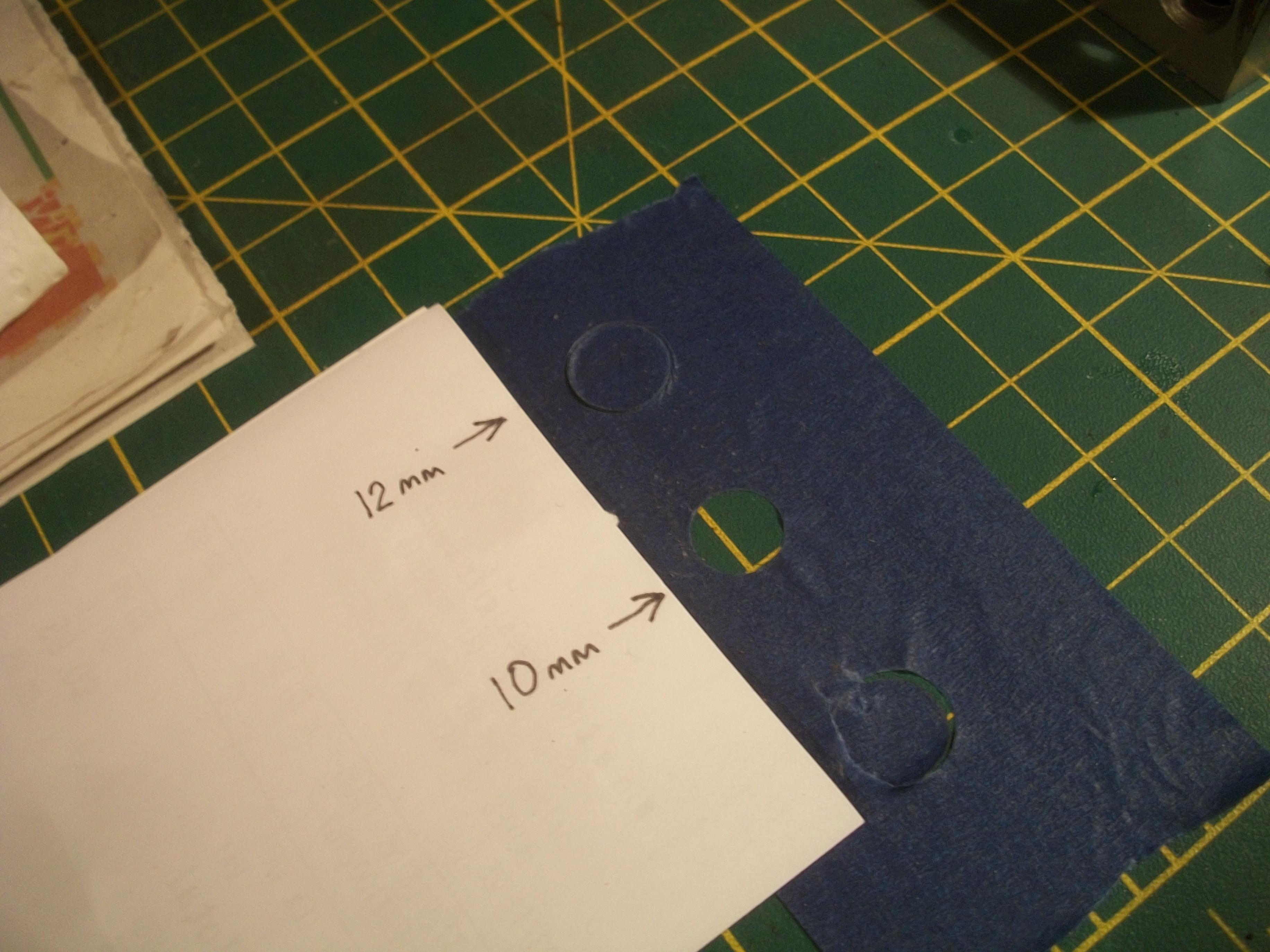
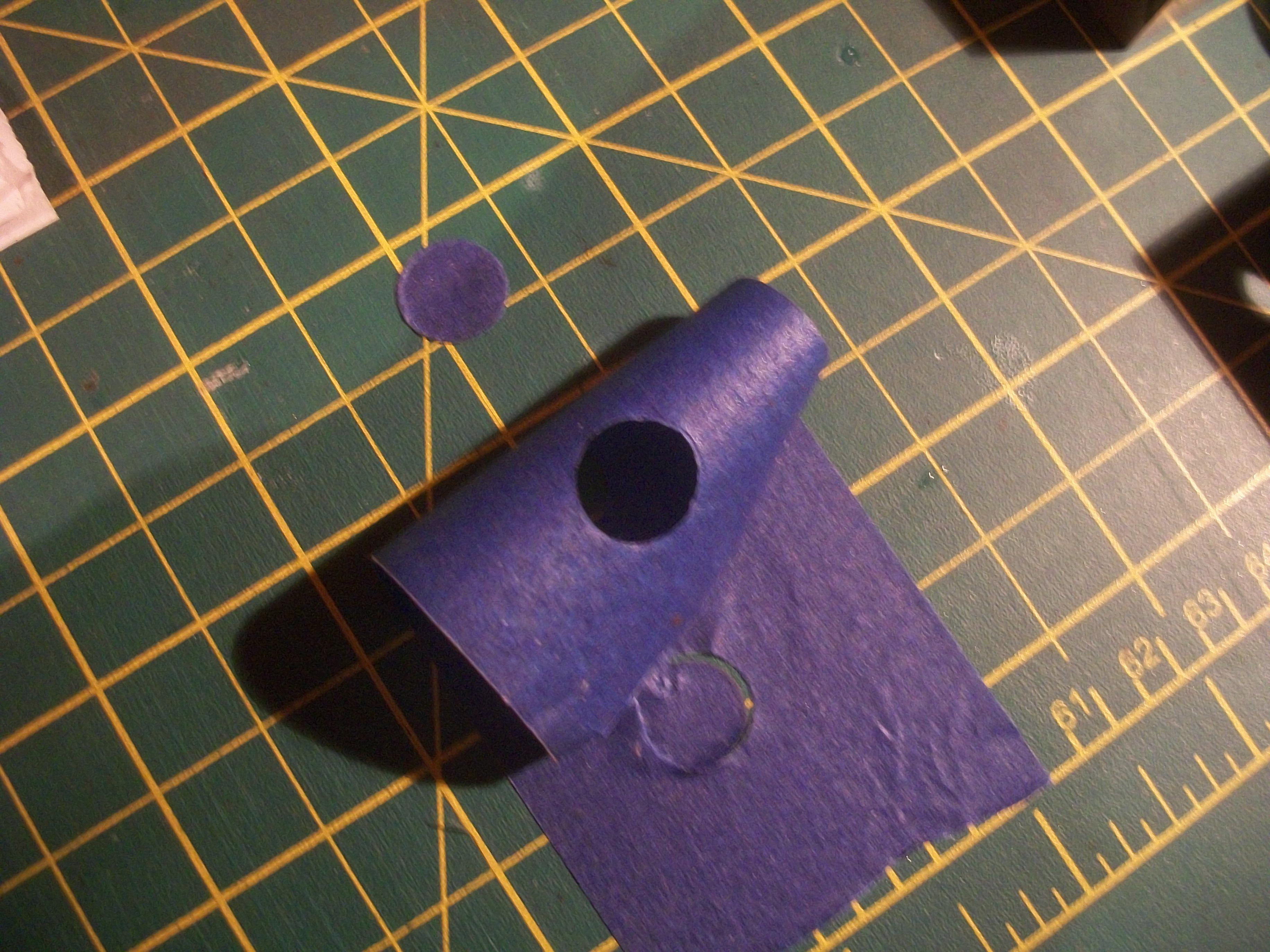
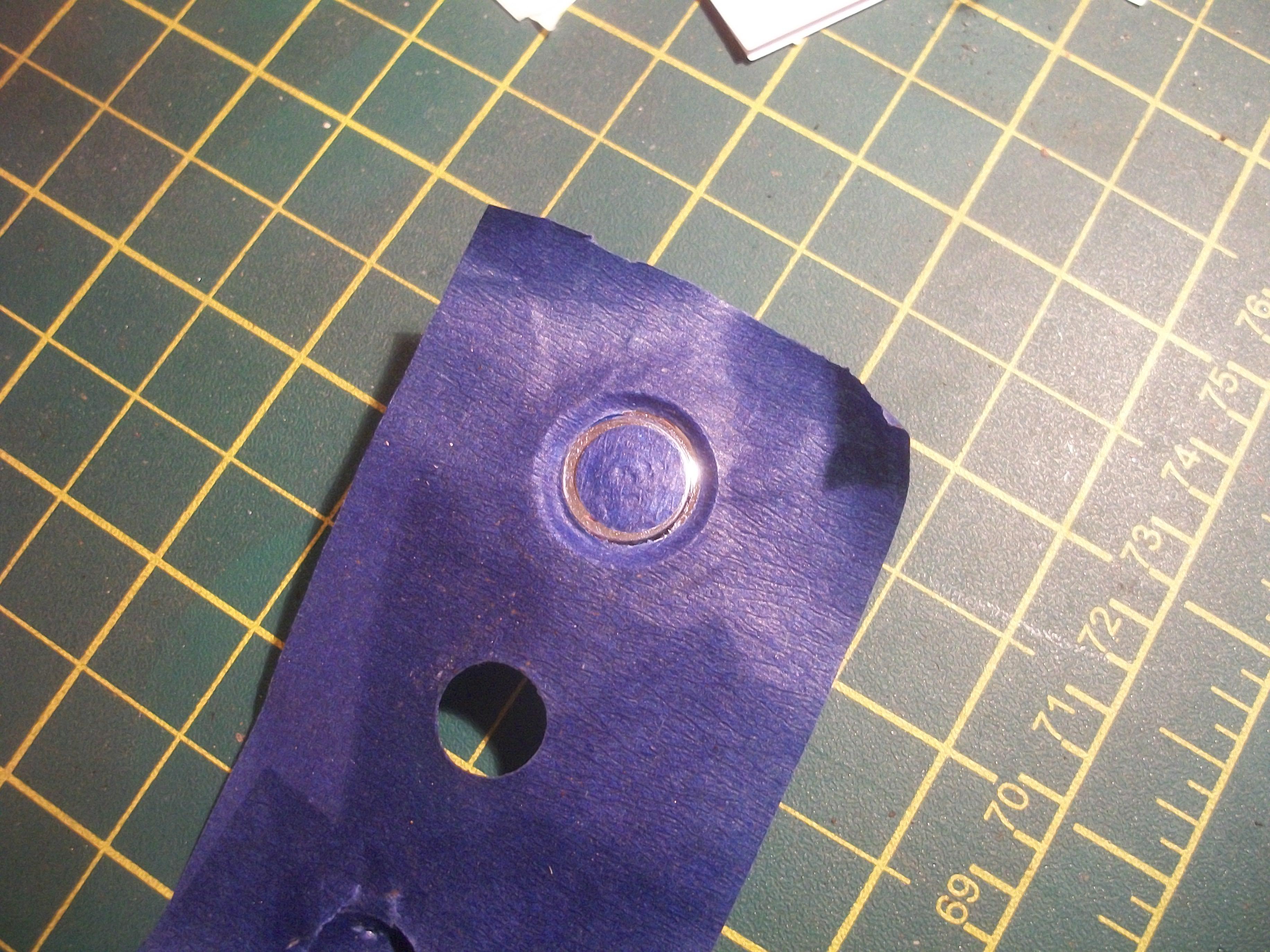
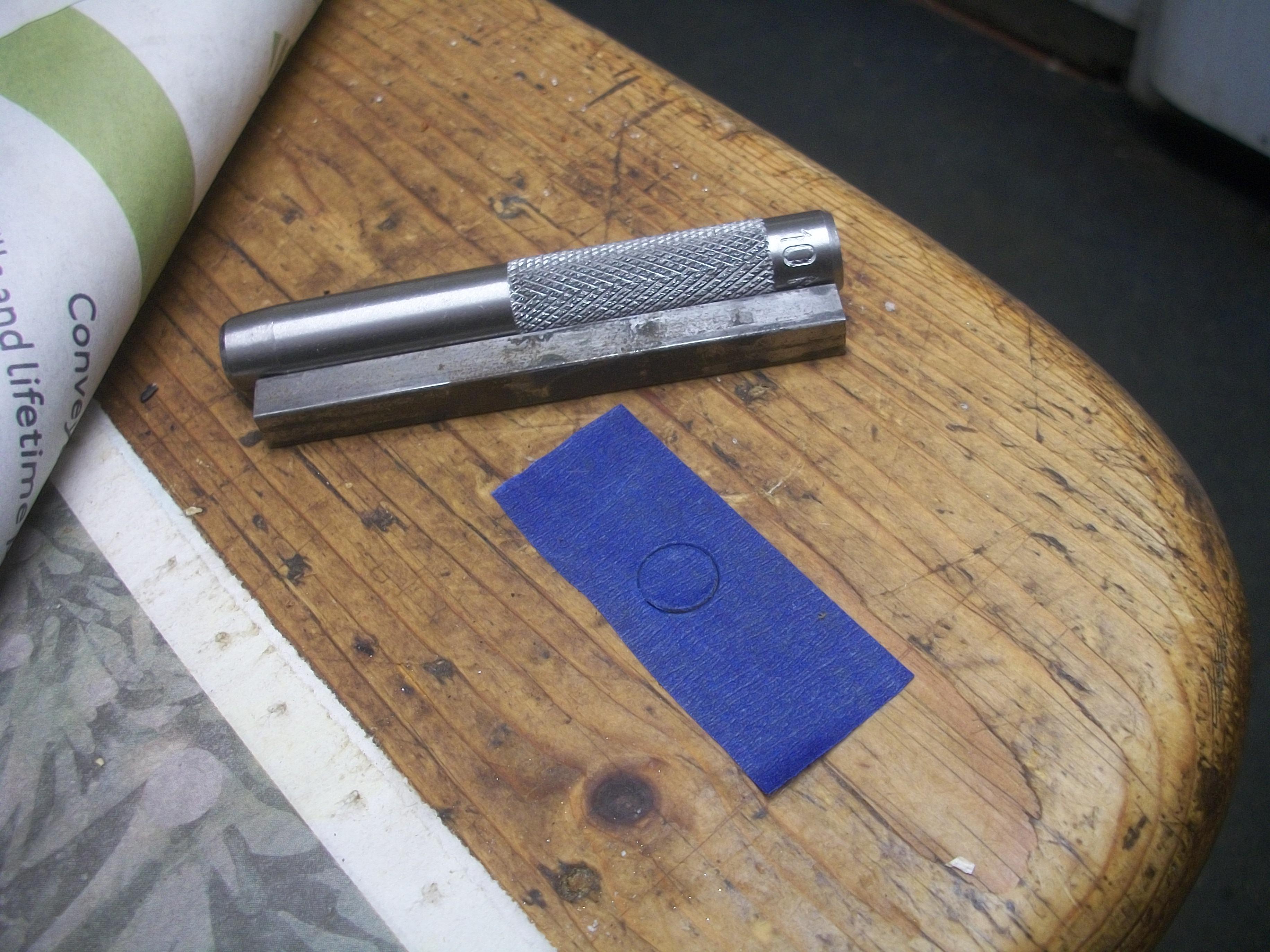
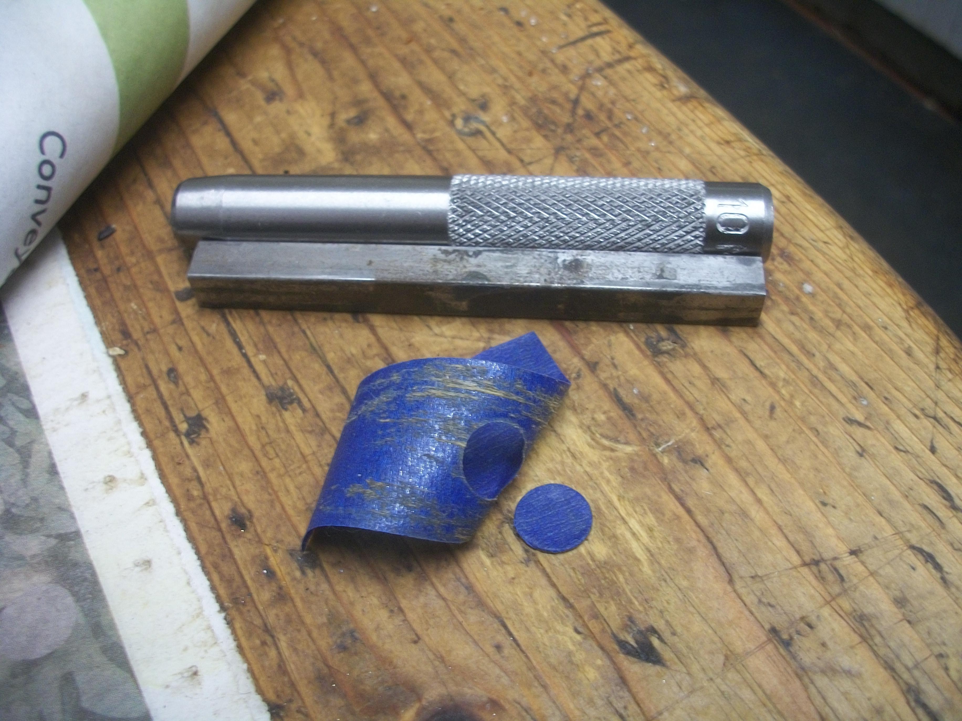
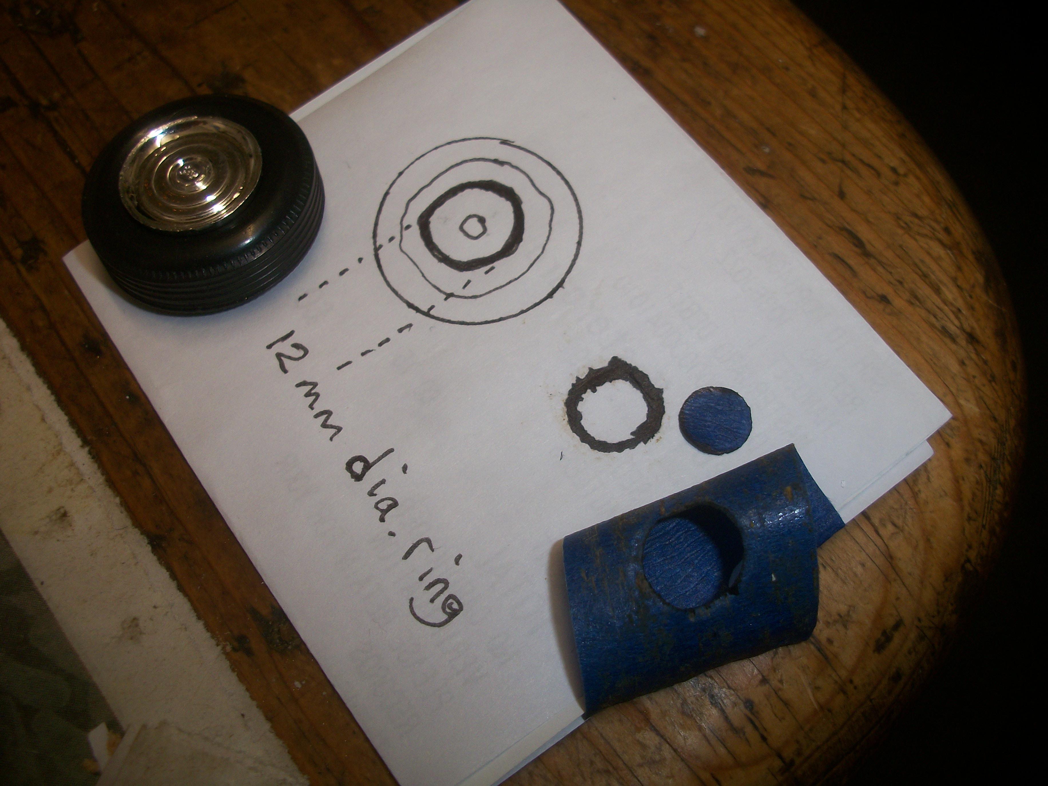
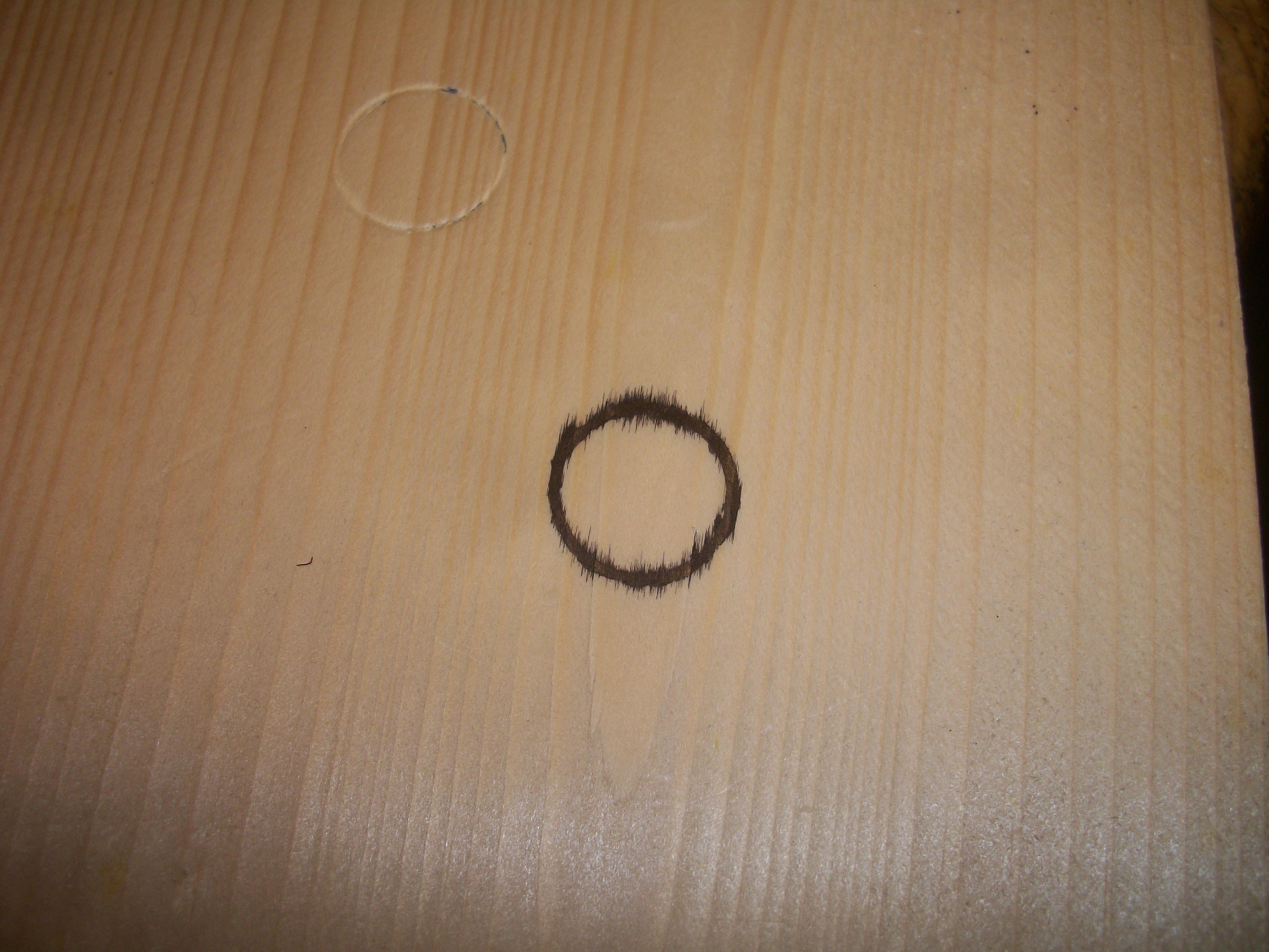
Today I was able to make some progress with the circle cutting process . . . This time I placed the piece of wide blue masking tape onto the cutting mat, and I made sure to position the tape immediately above the support leg for my work surface. Also, I used the heavy mallet hammer instead of the smaller lightweight hammer. The 10 mm circle was cut out perfectly at the first attempt, whereas the 12 mm circle failed at the first attempt, but came out nicely at the second attempt . . . Then came the tricky process of precisely positioning the two pieces of masking tape onto an actual chrome wheel. The 10 mm disc piece went on first, and the 12 mm outer surround piece was pressed into place secondly . . . I carefully pressed down the edges of both pieces of masking tape, to minimise any leakage or bleeding of the permanent black marker pen when it was applied next. While the end result is not great, I can see how this works now. Hopefully I can learn from this first application of one black circle on a spare wheel, and maybe I can improve as I carry out further attempts of the whole process. This is probably one of the more difficult tasks that I have come across during my model building career. The heavy hammer does need to be wacked hard multiple times on the head of the punch, and the two punches did require some grinding of the cutting edges. Using the cutting mat as a base is a good idea for sure, but I might try brushing on some black Vallejo acrylic paint rather than using the marker pen. David
-
Rolls-Royce No Chemicals, No Paint, No Harmful Glues
Anglia105E replied to Anglia105E's topic in WIP: Model Cars
Dragged nail test done . . . Smooth -
Rolls-Royce No Chemicals, No Paint, No Harmful Glues
Anglia105E replied to Anglia105E's topic in WIP: Model Cars
My cutting mat is super smooth ! -
Rolls-Royce No Chemicals, No Paint, No Harmful Glues
Anglia105E replied to Anglia105E's topic in WIP: Model Cars
Okay Jose . . . That sounds like good advice to me ! David -
Rolls-Royce No Chemicals, No Paint, No Harmful Glues
Anglia105E replied to Anglia105E's topic in WIP: Model Cars
Interesting that you should mention the surface of the table Jose, as I was thinking that I should be using a smooth surface rather than a more porous surface. Thanks, David -
Rolls-Royce No Chemicals, No Paint, No Harmful Glues
Anglia105E replied to Anglia105E's topic in WIP: Model Cars
Don't worry Mark, and over the next few days I shall be trying out various different methods . . . I have brought down my vice from the loft, and also my mini grinder so I can sharpen the cutting edges of these hollow punches . . . I watched this video, which explains how the cheap Chinese hollow punch set does not cut well out of the box. The man shows how to use a grind stone and a block of wood for a guide to sharpen the angled cutting edge of the punch . . . Here is the link if you want to watch the YouTube video . . . https://www.youtube.com/watch?v=wYLCTk38HDs David -
Rolls-Royce No Chemicals, No Paint, No Harmful Glues
Anglia105E replied to Anglia105E's topic in WIP: Model Cars
Thanks Mark . . . That is an interesting alternative, and I hadn't thought of painting the whole wheel cover in black. Further along during this process I could pursue that approach, particularly if the current approach is not working . . . All suggestions and comments are most welcome, thanks to all . David -
Rolls-Royce No Chemicals, No Paint, No Harmful Glues
Anglia105E replied to Anglia105E's topic in WIP: Model Cars
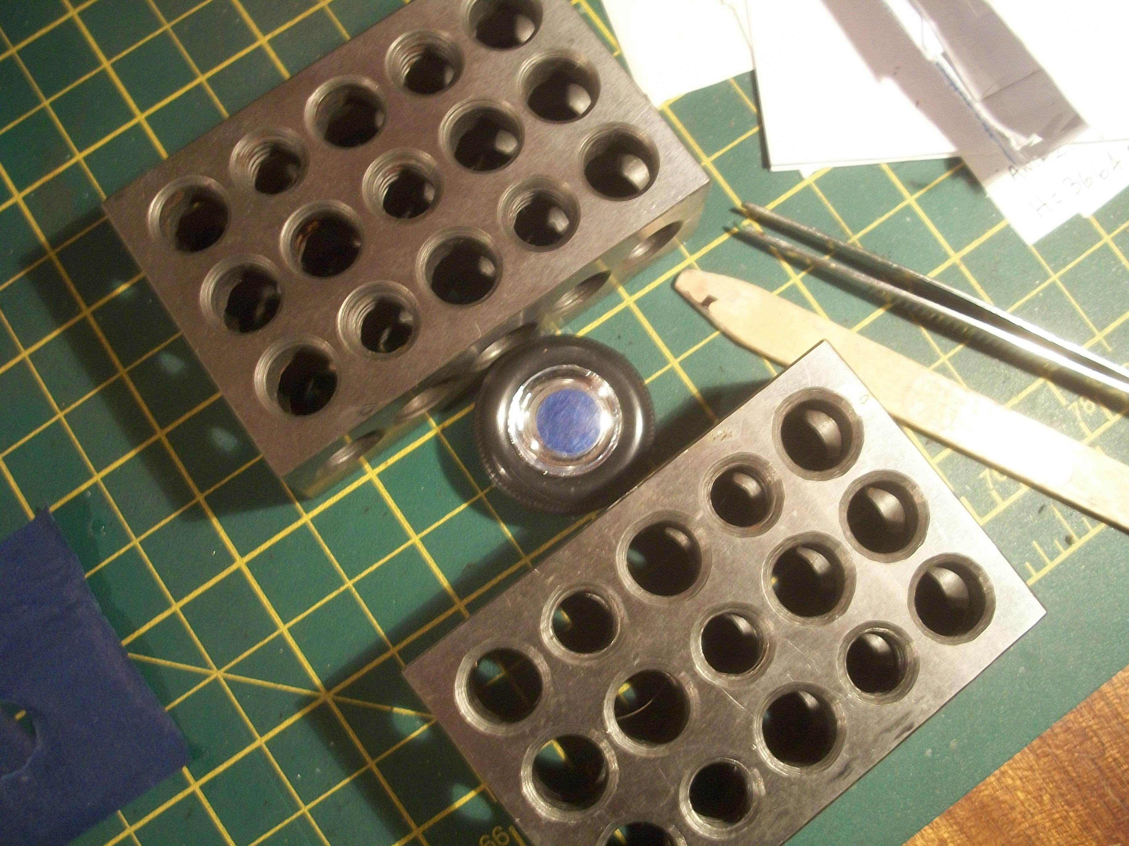
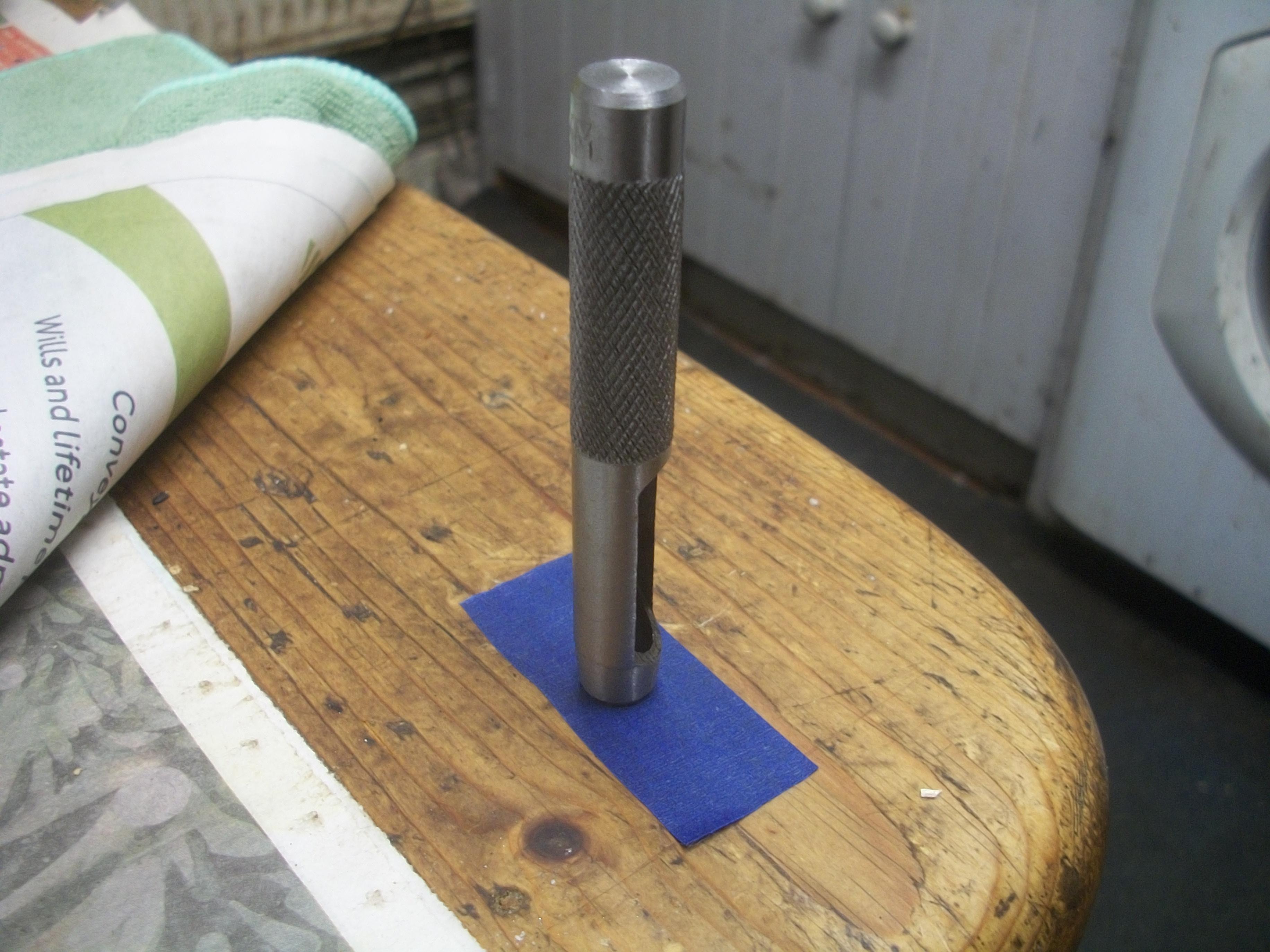
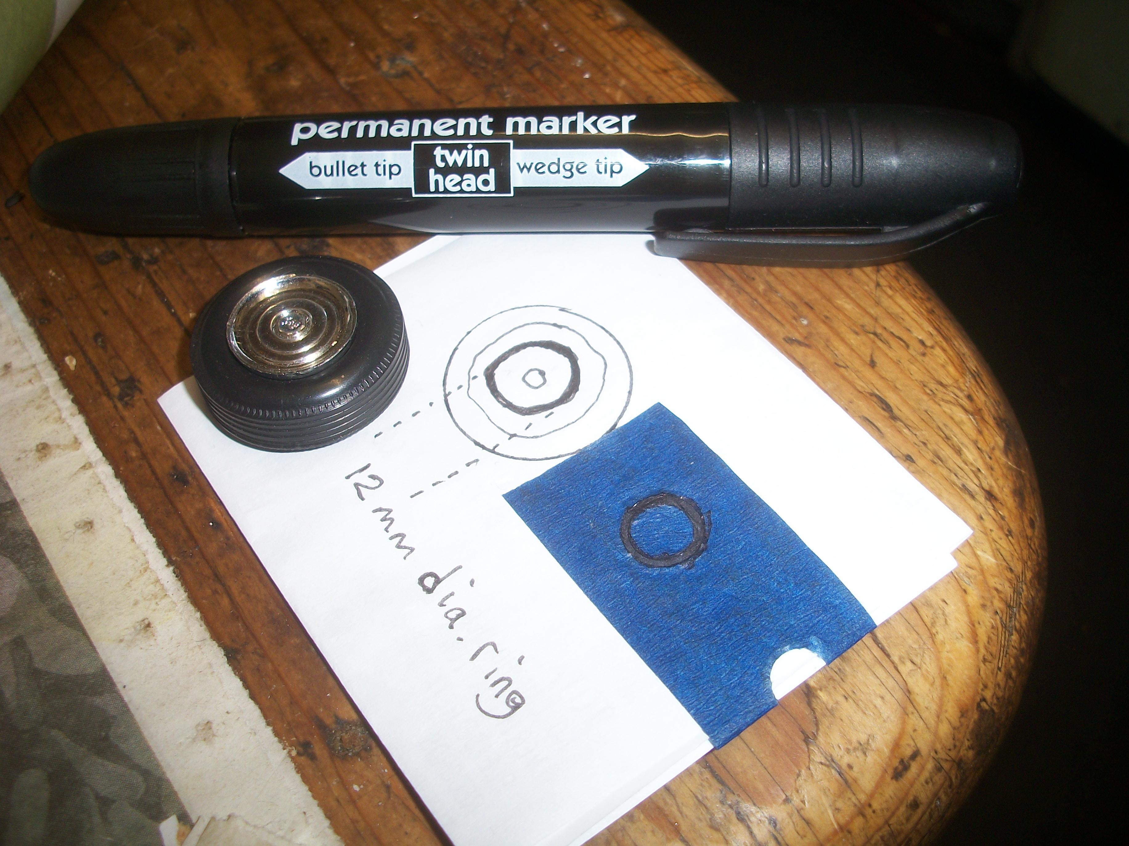
Thank you John . . . I shall probably use one corner of my large cutting mat as a sacrificial surface, which is a good suggestion. The tool does appear to be cheaply produced as you say, so it is possible that the cutting edge is not as sharp as it needs to be. I am testing by using an 8 mm punch for the central circle, and then a 10 mm punch for the outer circle . . . When I do the actual pieces after the tests, I shall use 10 mm for the central piece and 12 mm for the outer piece. The two pieces of masking tape will be transferred to the actual chrome road wheel in order to apply the black permanent marker pen, which should not bleed under the tape . . . David -
Rolls-Royce No Chemicals, No Paint, No Harmful Glues
Anglia105E replied to Anglia105E's topic in WIP: Model Cars
Thank you Les . . . I do have an old leather belt, so that might help. Also your suggestion to use a vice is a good idea, so I might try that approach. Maybe I need some new wide blue masking tape . . . So far Les, I haven't tried an actual Silver Cloud wheel, as I am experimenting on flat surfaces first, but I do have plenty of wheels for tests. David -
Rolls-Royce No Chemicals, No Paint, No Harmful Glues
Anglia105E replied to Anglia105E's topic in WIP: Model Cars
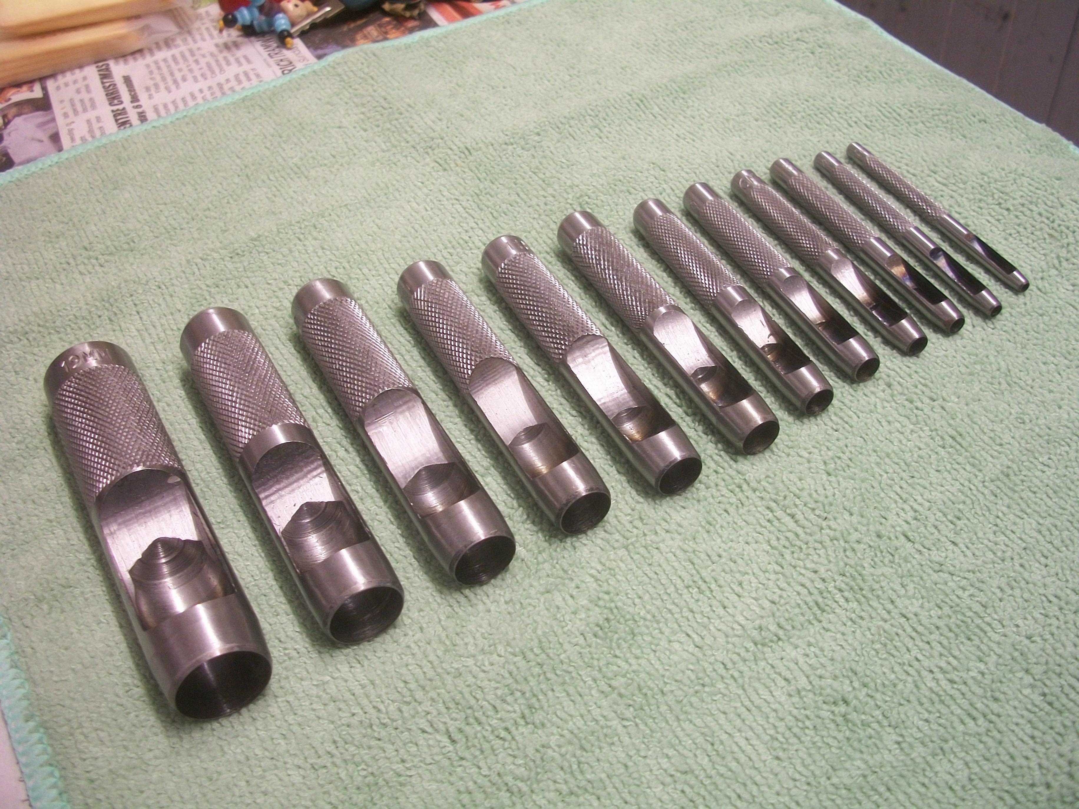
The Hollow Punch Set was delivered today, and this evening I began testing the procedure to see what might be possible . . . Several issues were noted, as I tried different methods of using this tool. The first attempt involved laying a piece of wide blue masking tape directly onto the wooden table top surface. The smaller centre circle seemed to cut out okay, but the larger circle from which I needed the outer piece of tape, was not really successful. Then I tried using a piece of styrene sheet instead of the table top. Also, I noted that the black permanent marker pen was bleeding under the tape, but this was mainly because I applied the black marker to some paper that was too absorbent . . . The styrene sheet did not make much difference, so I tried using a block of wood and again there was no significant improvement . . . I haven't tried using my cutting mat so far, but this can be tried out at some point. I am using a lightweight hammer, until I can find my heavy mallet, so this might help later . . . Possibly the wide blue masking tape is at fault here, because although it is very good tape, the roll has been stored in the loft, which has now become much colder and also rather damp . . . This process needs a re-think, and I am not yet sure if it will work for these chrome wheel embellishments. I was expecting this tool to be easier to use. to be honest. David
-
This is a difficult kit in 1:32 scale Patrick . . . I wouldn't refer to your build as rubbish, so it is what it is. Simple and basic, not rubbish ! David W.
-
Rolls-Royce No Chemicals, No Paint, No Harmful Glues
Anglia105E replied to Anglia105E's topic in WIP: Model Cars
Okay Mark . . . Harbor Freight sounds good and we don't have those stores here in England . . . This might turn out to be a very useful tool. David -
Rolls-Royce No Chemicals, No Paint, No Harmful Glues
Anglia105E replied to Anglia105E's topic in WIP: Model Cars
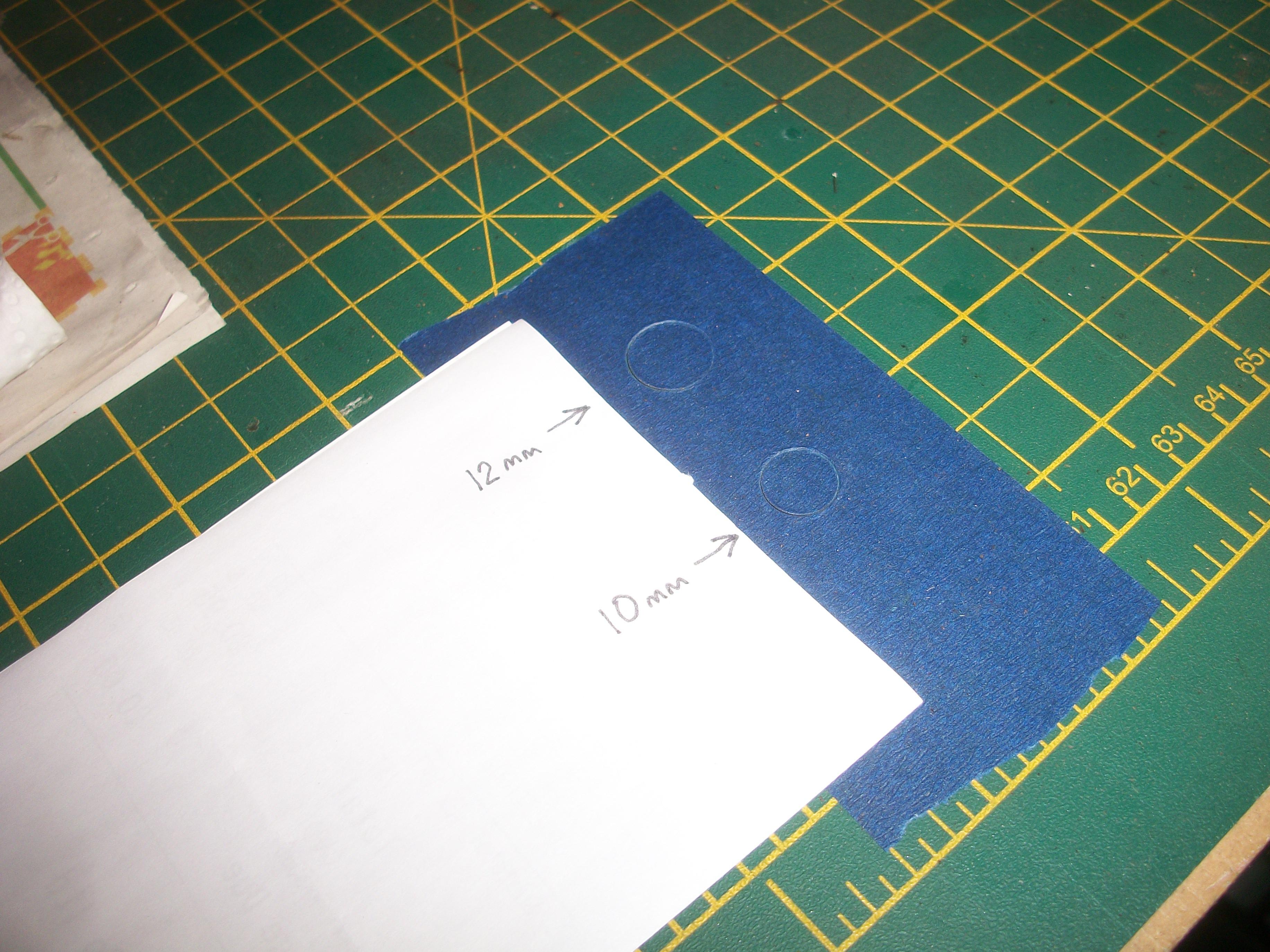
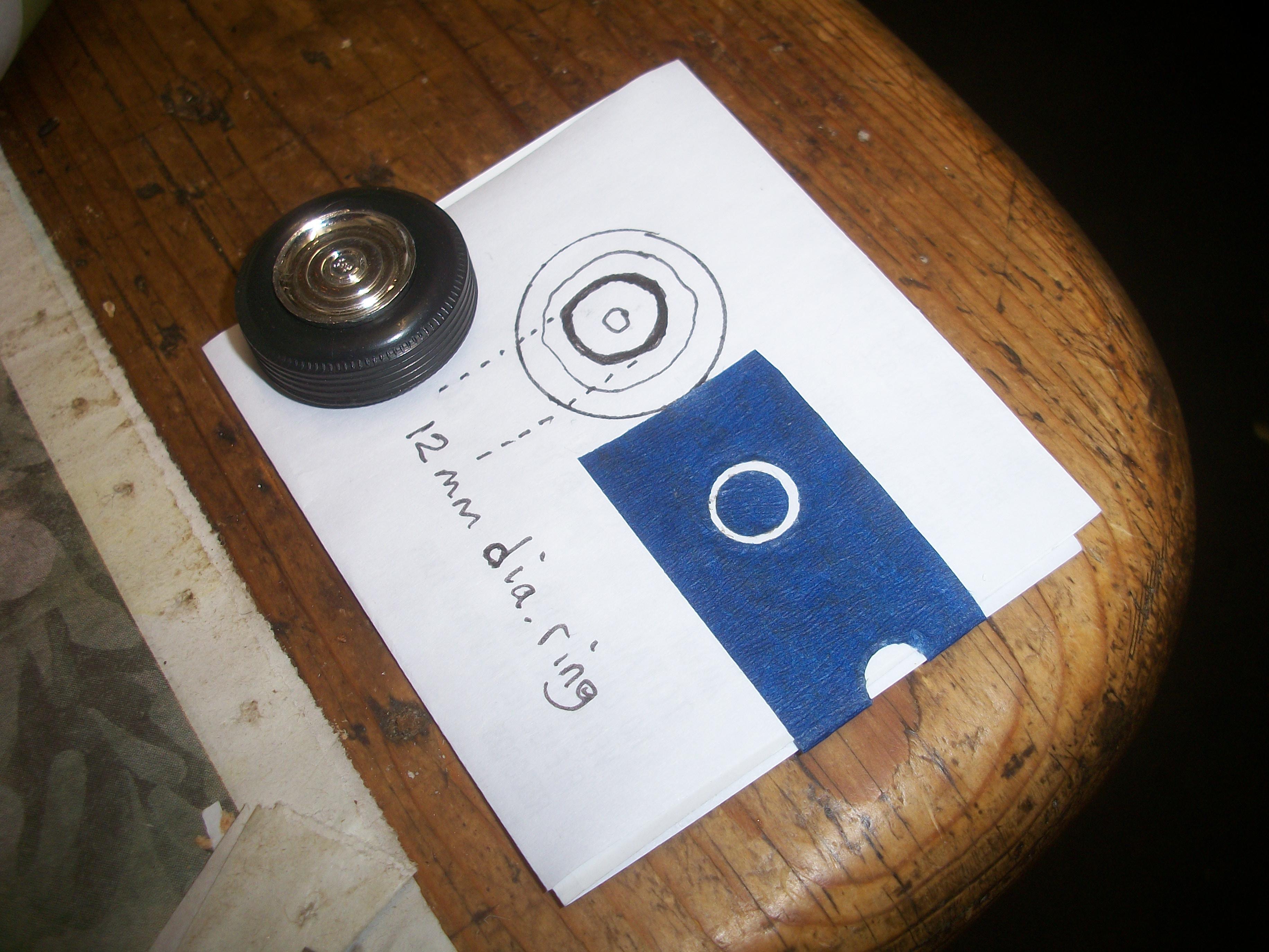
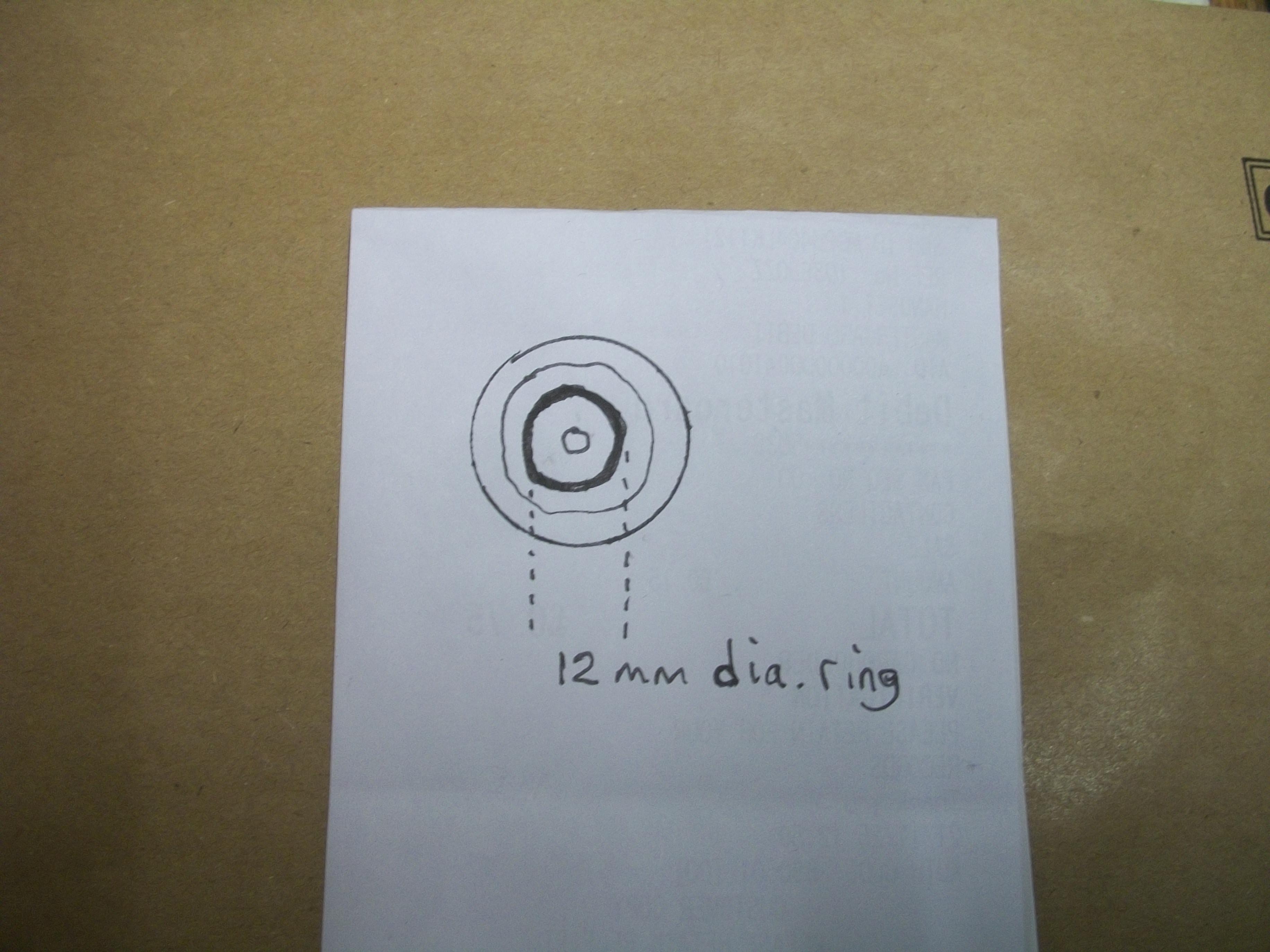
Mark . . . The outer diameter of the ring that I have to paint in black is 12 mm, as shown in my sketch and the outer diameter of the wheel is 17 mm. This tool on Ebay should be just what I need, and it doesn't cost much. You could place an order on Ebay if you want one of these kits for yourself ? David -
Rolls-Royce No Chemicals, No Paint, No Harmful Glues
Anglia105E replied to Anglia105E's topic in WIP: Model Cars
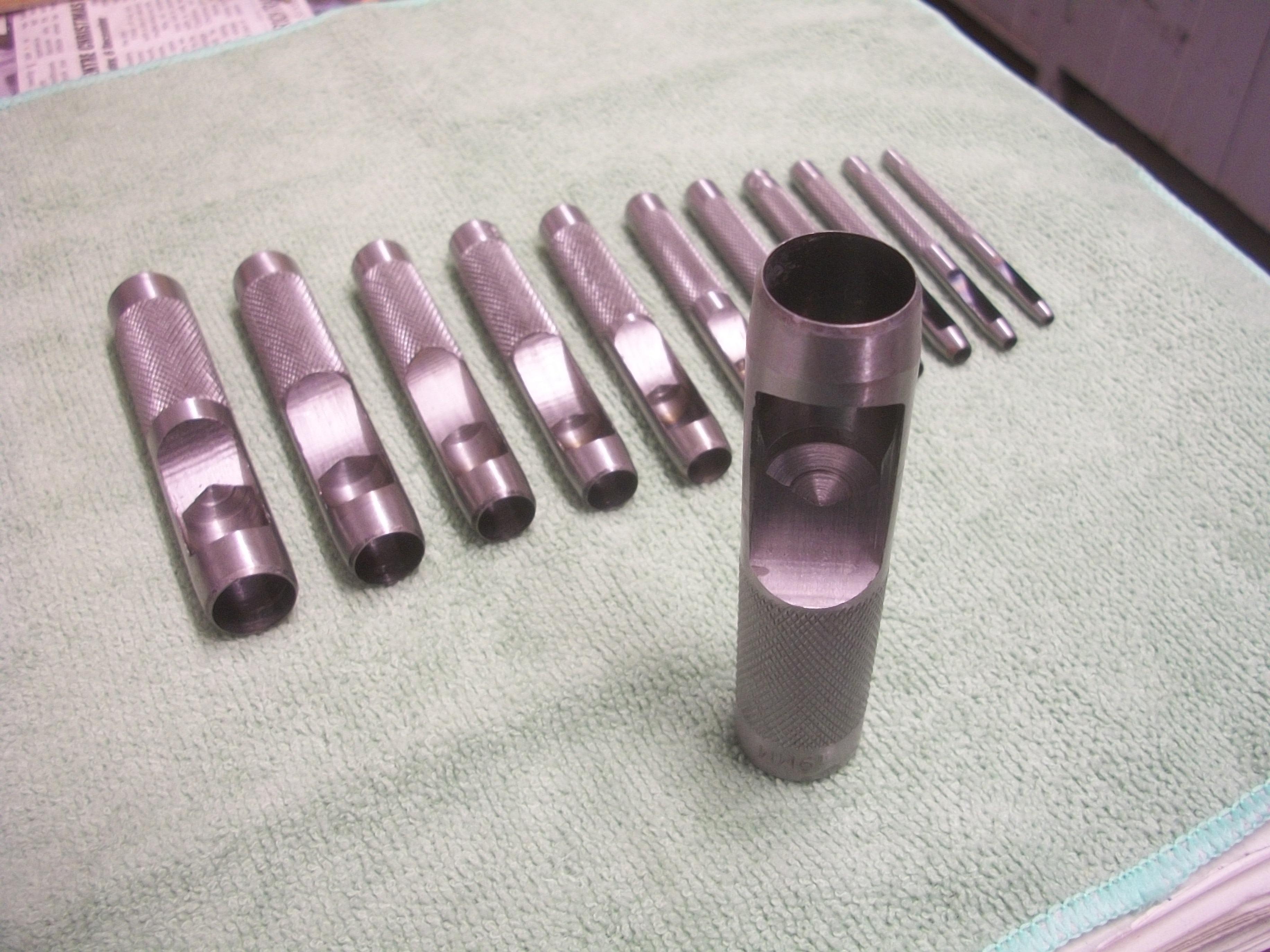
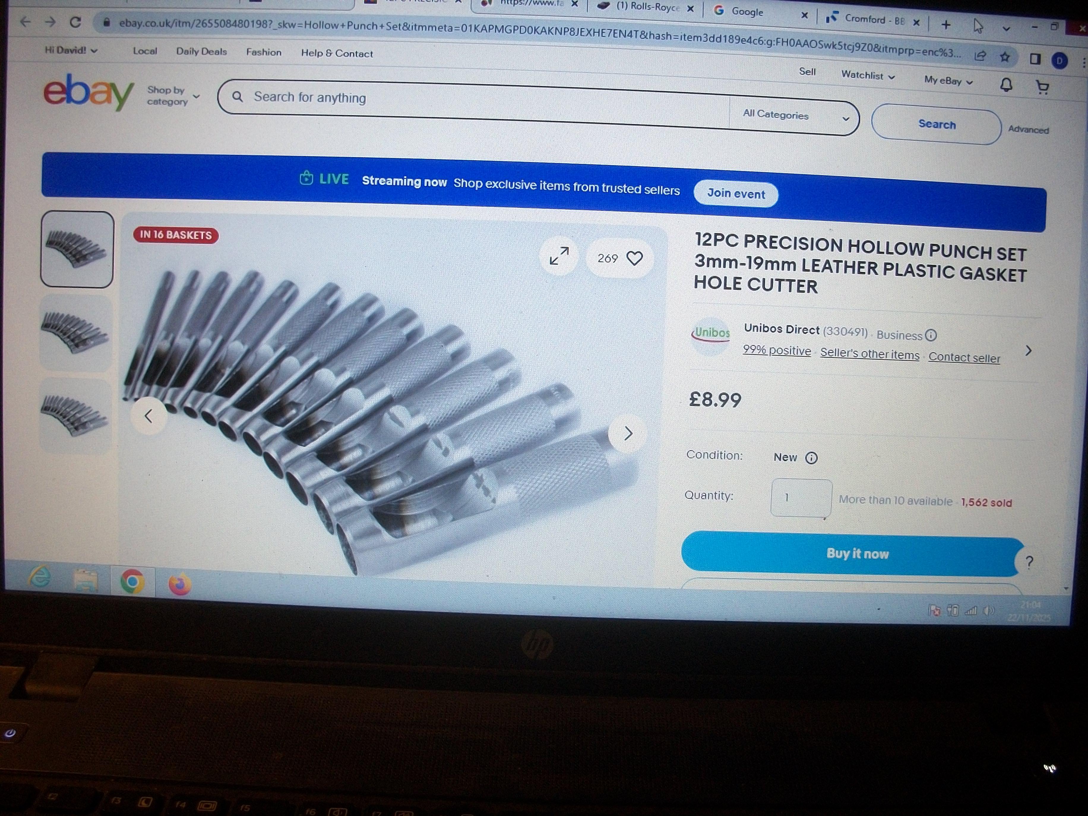
Good thinking Les . . . That would indeed be a possibility. I have just found a product on Ebay, which is only £8.99 and free delivery. Here is the link :https://www.ebay.co.uk/itm/265508480198?_skw=Hollow+Punch+Set&itmmeta=01KAPMGPD0KAKNP8JEXHE7EN4T&hash=item3dd189e4c6:g:FH0AAOSwk5tcj9Z0&itmprp=enc%3AAQAKAAAA8FkggFvd1GGDu0w3yXCmi1ftgxk--rXBNqSoPmtJWNWfYkuCIAdoc%2BYohQec%2BqfWg6LEuf4ZKAuJolZcMlE6DsQRgAe%2F3eoK18kG31kUxXnffmA7%2FDP%2F7hGDYLyeIMMerSxIFBnw8Er5AY%2FPxJCRXlNvRO08lopUt50BX4tEPkt5YQeRSrD67xNzJmzmzRCOi4K1TCD1%2B7%2BoXwF2LMWIyneCsTU1oOt%2B8734BWK0C13do%2F%2Bv5RLia58XGtRVgv9v6Atg%2FXeYF%2BBXlR47iDE6ZCN3%2Fte%2F0E791KvW32Po3U6oZ7xt9yhHBtI5DCClEmkp1g%3D%3D|tkp%3ABFBM9ubC1NVm Two photos below also David
-
Rolls-Royce No Chemicals, No Paint, No Harmful Glues
Anglia105E replied to Anglia105E's topic in WIP: Model Cars
Thanks John . . . I would think a fabric or leather working store is the most likely type of store for this product . . . David -
Rolls-Royce No Chemicals, No Paint, No Harmful Glues
Anglia105E replied to Anglia105E's topic in WIP: Model Cars
Okay Les thanks . . . I shall do some browsing when I get a moment this evening. Certainly, I am in need of something clever to do these rings . . . David -
Rolls-Royce No Chemicals, No Paint, No Harmful Glues
Anglia105E replied to Anglia105E's topic in WIP: Model Cars
That would take a steady hand Jose . . . Not sure I could do that. Thinking about it, the wheels don't rotate now. Interesting suggestion though, so thanks for that ! David