absmiami
-
Posts
4,779 -
Joined
-
Last visited
Content Type
Profiles
Forums
Events
Gallery
Everything posted by absmiami
-
and on a completely different note here's a link to some marvelous Gulf team race car porn.. www.rofgo.com/collection
-
wait a minute ... I'm missing a connection here ... It appears that you were the drafter ?? so this was really a two continent project ?? and yes I've seen the 43th sc engine who's going to dare to make the throttle link/arm assembly in 43rd scale //// ??? So if I finish mine in 24th scale I can request a mod? and did you draw the Ford DOHC ? and have I opened up another can of worms ? and do you have the Becassa app also ??
-
1907 Rolls Royce Silver Ghost, 1/24 Finecast metal kit
absmiami replied to Matt Bacon's topic in WIP: Model Cars
my favorite Brit expression - Oh Dear ... -
1907 Rolls Royce Silver Ghost, 1/24 Finecast metal kit
absmiami replied to Matt Bacon's topic in WIP: Model Cars
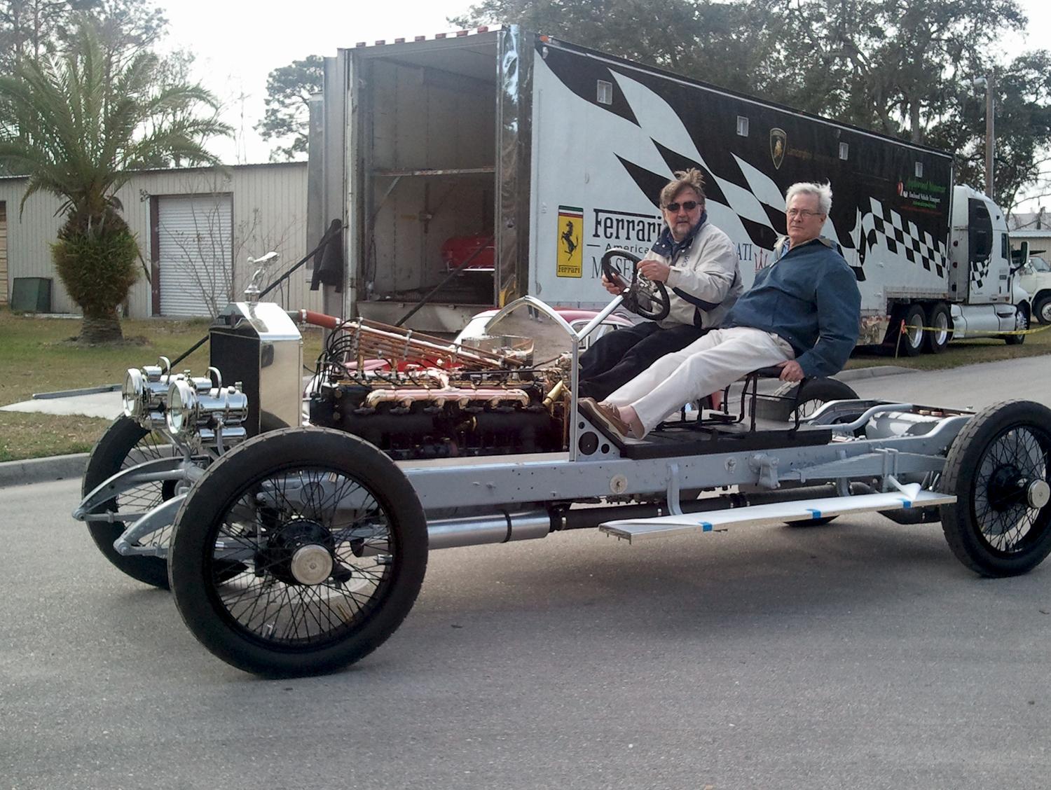
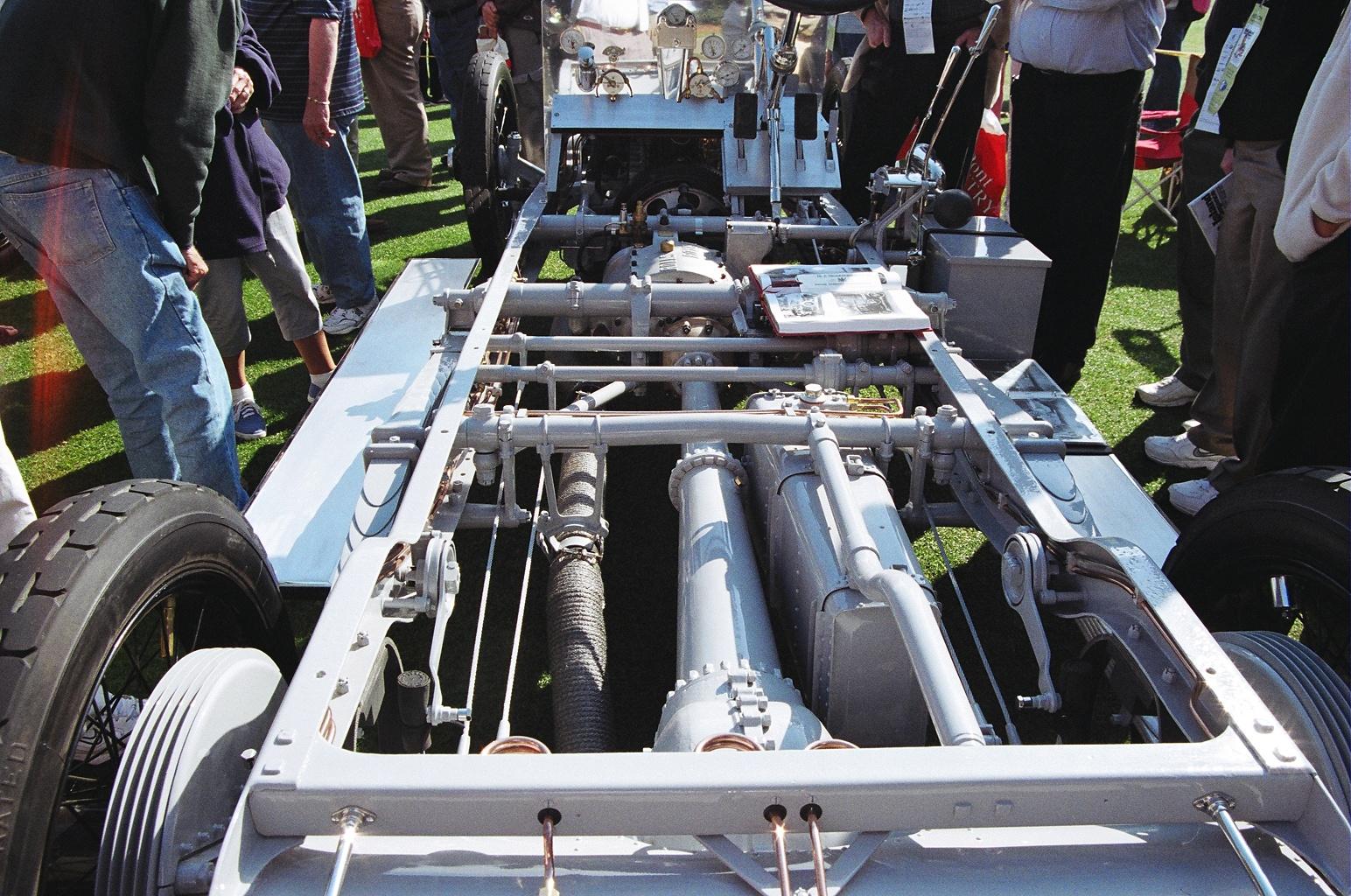
nope you're gonna be mad at me - or maybe not ... the car that i photographed is a 1914 silver ghost - this is another shot of the same chassis I'm pretty sure that the kit instructions - famously vague - threw you off looks like the axle sits at the extreme end of the leaf springs and that the springs are attached to the chassis further forward. this matches the chassis drawings of the car that float around the internet ... now about that third leaf spring? maybe Finecast just enclosed a spare part //?? you may need a hand from some of our British forum members to settle this ....
-
1907 Rolls Royce Silver Ghost, 1/24 Finecast metal kit
absmiami replied to Matt Bacon's topic in WIP: Model Cars
I think you can tell that this display chassis had a different rear suspension layout Finecast was pretty careful with their research - I'm assuming that the this is a later chassis - as the Ghost was produced for years and almost certainly went thru lots of changes ...
-
1907 Rolls Royce Silver Ghost, 1/24 Finecast metal kit
absmiami replied to Matt Bacon's topic in WIP: Model Cars
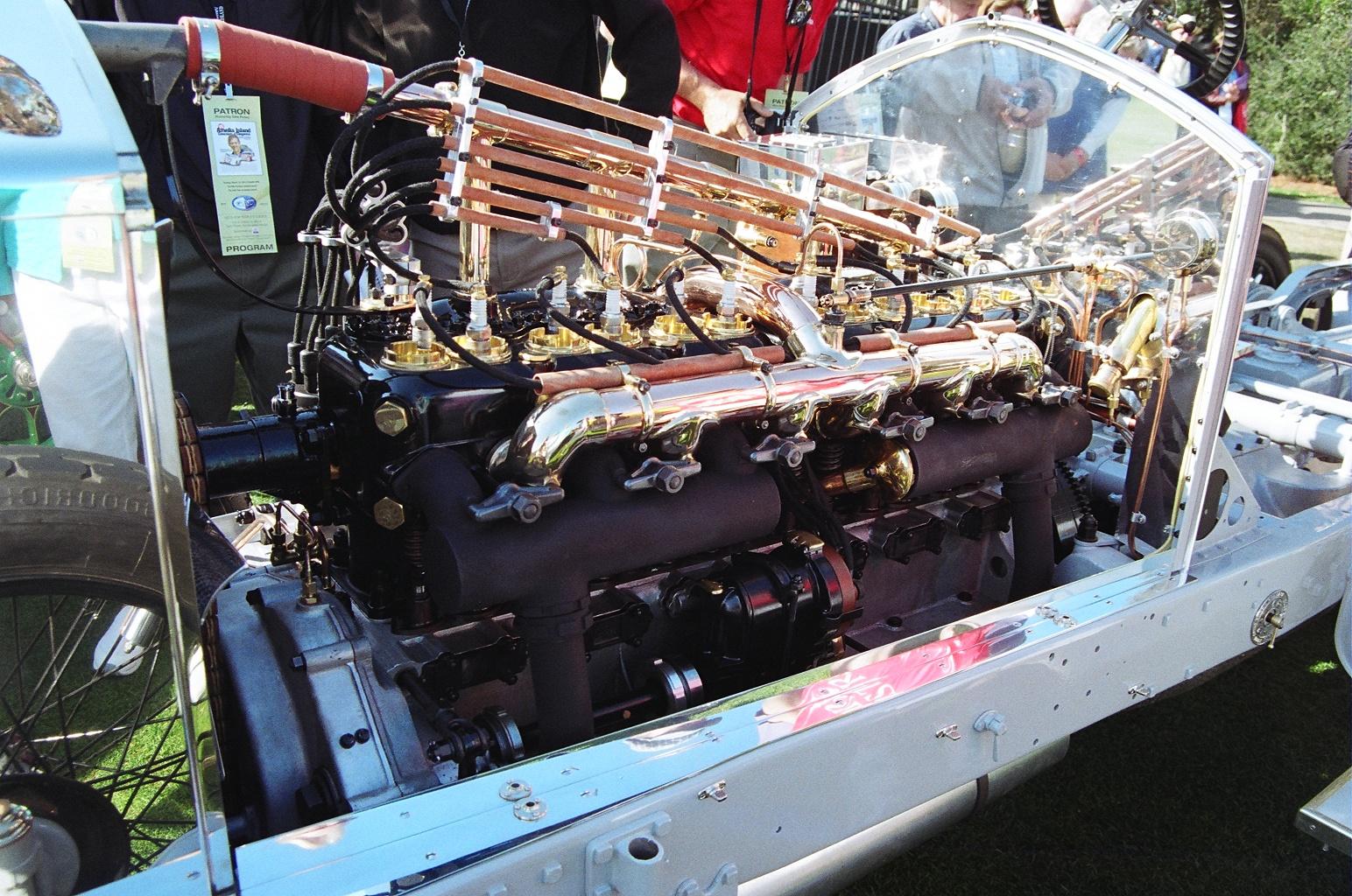
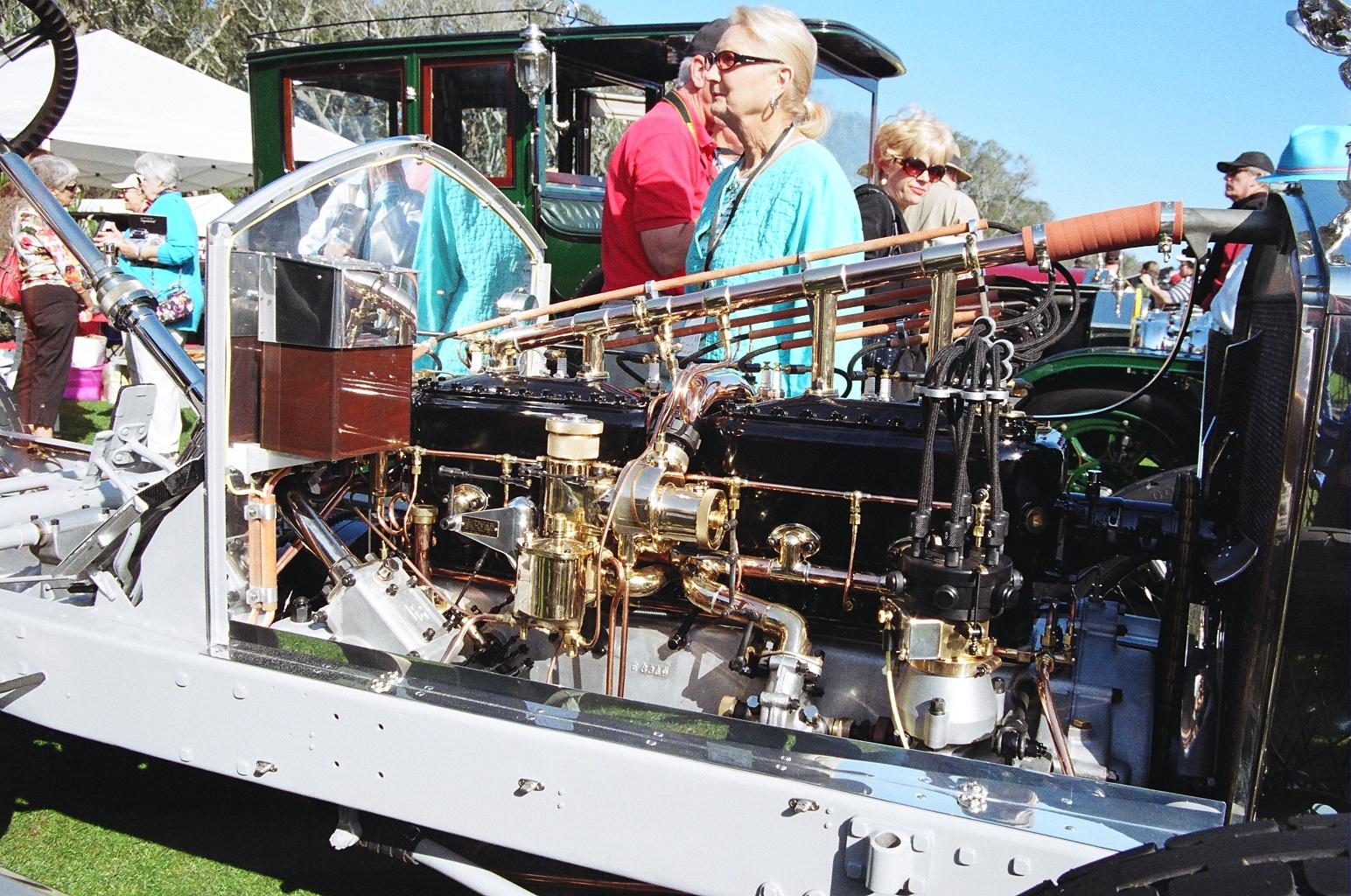
well - I'd say that your doing quite well don't bother separating the ignition wire tubes - enough is enough .. what a bonkers engine ...
-
1907 Rolls Royce Silver Ghost, 1/24 Finecast metal kit
absmiami replied to Matt Bacon's topic in WIP: Model Cars
So. I’m rather enjoying this build. I think everyone is ... I took some photos of a Silver ghost display chassis w engine at Amelia - displayed maybe 7 yrs ago ... It appears to be this car or very close - would you like me to post a couple of them ? by the way I’ve built the Finecast Bugatti 59 and I’ve just purchased the Alfa Romeo P3 kit direct from their site. The Alfa, unfortunately, is a curbside kit - but it is the only choice in24th scale ... I’m a fan of their kits anyway ... have been for many years... -
That’s a rule ...
-
1949 Ferrari MM Le Mans Winner
absmiami replied to Gramps46's topic in WIP: Other Racing: Road Racing, Land Speed Racers
Michael Quarterman's wife has shared news of husband Michael's serious illness on the Grand Prix Modeler's Association forum hoping Michael will pull through - I'll pass on any more news that is posted on the GPMA forum abs -
(HRM) Shelby Cobra Daytona Coupe
absmiami replied to Venom's topic in WIP: Other Racing: Road Racing, Land Speed Racers
Wait : ... ... girls ? well. You’ve got lots of horses ... -
(HRM) Shelby Cobra Daytona Coupe
absmiami replied to Venom's topic in WIP: Other Racing: Road Racing, Land Speed Racers
Wyoming? Well your winters must be Like my summers ... you’ll have enough time to start and even finish this ! Let me know if you need a photo of something ... -
(HRM) Shelby Cobra Daytona Coupe
absmiami replied to Venom's topic in WIP: Other Racing: Road Racing, Land Speed Racers
And Brad stubbornly doesn’t blog, or trawl forums, do we can all heap praise on these pages and he will blissfully have no clue ... -
(HRM) Shelby Cobra Daytona Coupe
absmiami replied to Venom's topic in WIP: Other Racing: Road Racing, Land Speed Racers
For those forum members who don’t know - I think most of you do - the kit is all resin cast - thus no parts trees - I happened to speak with the “factory” yesterday. Brad is prepping some more kits for Randy D. He is one of the last of the Mohicans - the effort required to mold and cast these parts is fantastic - and the quality of this kit rivals MFH - soon this will all be overtaken by 3D printing - But we can leave that debate for another time - for now - this will be really cool to watch - the Simeone museum in Philly has one of the first Daytona Coupes - in dented and chipped unrestored glory. -
Cooper barn find
absmiami replied to absmiami's topic in WIP: Other Racing: Road Racing, Land Speed Racers
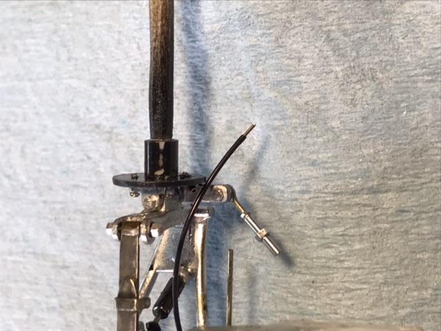
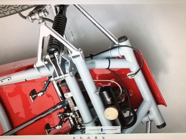
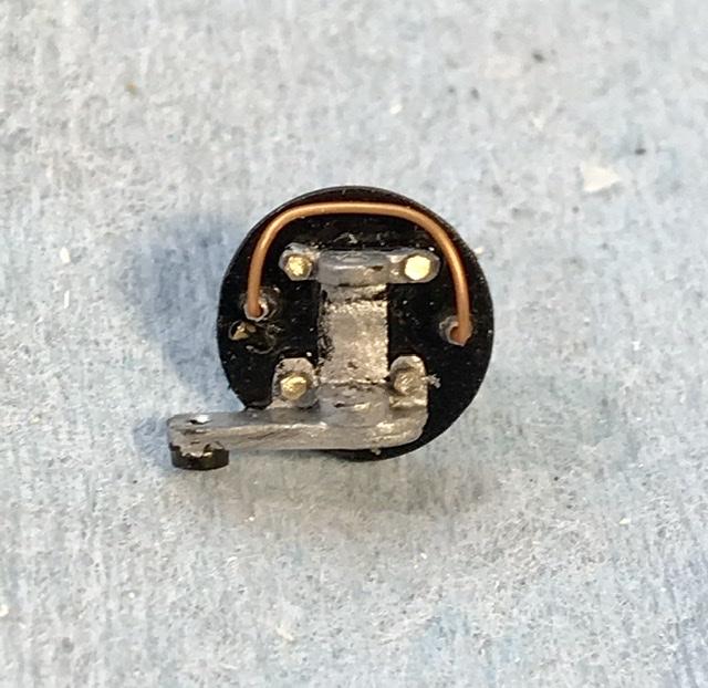
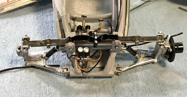
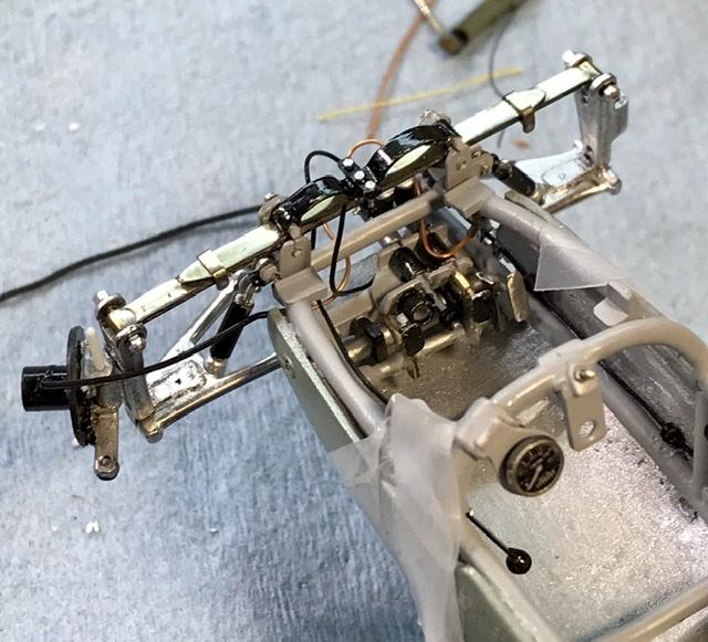
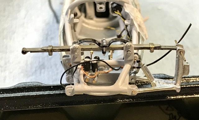
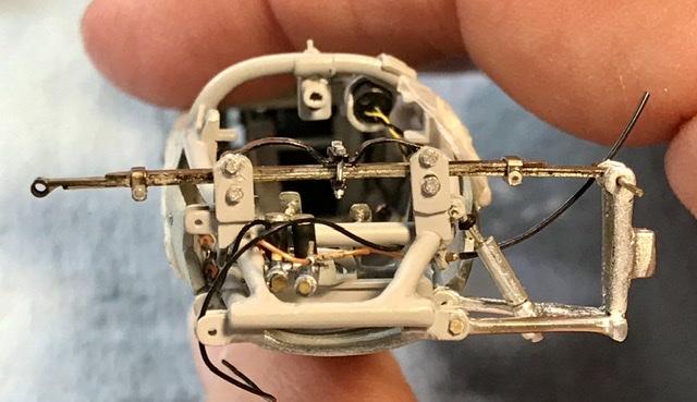
The steering arm is set with my top secret / xtra special alignment tooth picks.... now about that spare wire that loops thru the front of the frame without a destination. That is the end of the park brake cable. The picture of the real car frame is from the Canepa site. They have a terrific walk-a-round of a Cooper Mark 9 with some suspension updates that is for sale - got a spare 100,000 ?? That picture solved my “where does the park brake cable go” mystery - which of course has kept me up many recent nights - thank you Bruce Canepa ...
-
Cooper barn find
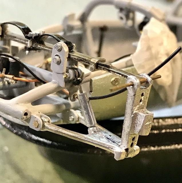
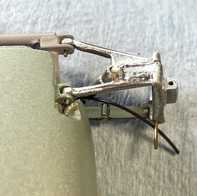
absmiami replied to absmiami's topic in WIP: Other Racing: Road Racing, Land Speed Racers
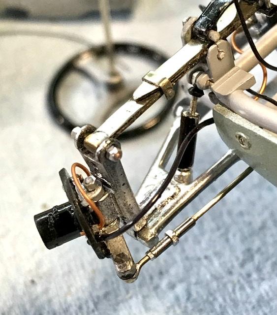
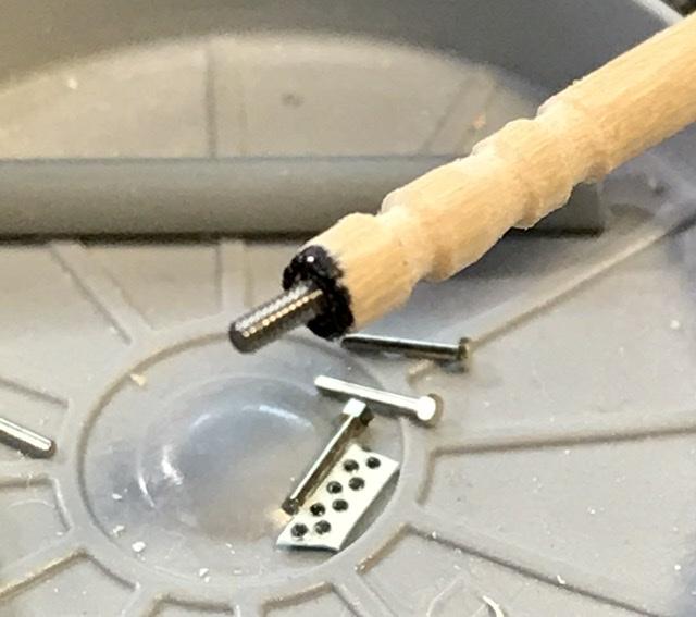
So the hub and spindle are finished and the bolt is screwed into the end of the steering arm - which was made months ago from brass - this was threaded by a corresponding thread tool - which is one of those tools that you don’t use very often but you’re glad that you have ...
-
Cooper barn find
absmiami replied to absmiami's topic in WIP: Other Racing: Road Racing, Land Speed Racers
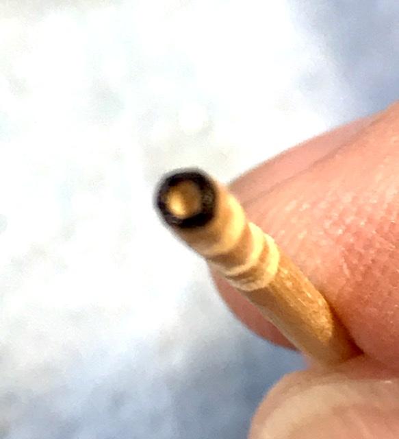
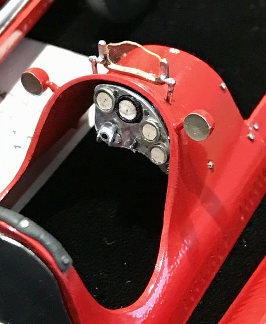
Got some bolts for the steering assembly - but the size of the bolt head- about .040 across flats - doesn’t match the opening in any of the mini wrenches that were sold with these - so I finally figured out how to make myself one. I drilled a .038 hole into the head of One of my favorite Toothpicks - jammed a bolt into the opening- dabbed a little CA glue over the surface - and voila - mini hex bolt wrench ...
-
Cooper barn find
absmiami replied to absmiami's topic in WIP: Other Racing: Road Racing, Land Speed Racers
I’m still mad at MFH for abandoning 24th scale GP kits. Imagine how great there Maserati 250F and Alfa 158-159 kits would have been. Maybe some day - just for laughs ? And why haven’t they produced Lotus sports cars in that scale ?? ??? -
Cooper barn find
absmiami replied to absmiami's topic in WIP: Other Racing: Road Racing, Land Speed Racers
Not likely ... couldn’t see how the expense of cleaning and/or preparing the very old molds would be practical. Would probably be easier / cheaper to 3D print them... and of course there would be the temptation to upgrade parts - such as wheels and tires. Assume that you know that the SMER repros of the Talbot Lago and Alfa Romeo are still readily available. And there is the option of FPP for the Vanwall - and his has an engine and excellent wire wheels ... I’m planning a Vanwall build - I’ll include a comparo if the Merit kit. And there are better / current resin kits of the Lotus 11 and of course the Jag D... back to the Cooper front suspension ... almost there ...
-
Cooper barn find
absmiami replied to absmiami's topic in WIP: Other Racing: Road Racing, Land Speed Racers
Well. You made me put the Maser back together ... -
Yup
-
Cooper barn find
absmiami replied to absmiami's topic in WIP: Other Racing: Road Racing, Land Speed Racers
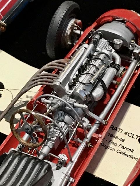
You might say that I have had a LONG relationship with Merit kits... the Maser was built MANY years ago. As was the Lotus 11. - Which is a curbside rep of a salt flats car that was hi-lited in - I think - Vintage Motorsport mag years ago ... I mite take another shot at the Maserati 48CLT ... since I built this one - I have photographed on at Goodwood and gotten more reference material. - would like to correct some errors in this build - there are several of them - and I’m trying to convince Reverend Davis to build one too ...
-
Cooper barn find
absmiami replied to absmiami's topic in WIP: Other Racing: Road Racing, Land Speed Racers
Well as a matter of fact ... -
Cooper barn find
absmiami replied to absmiami's topic in WIP: Other Racing: Road Racing, Land Speed Racers
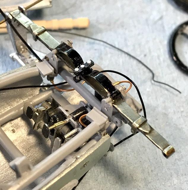
Thanks. I sprayed a coat of Alcad clear on them. - To avoid tarnish. And the larger bolts. — the “Russians” - are by Master Club .... -
This is really turning out nicely. Could I impose upon you to replace the fuel injector pipes with some polished alu ?? ??
-
Cooper barn find
absmiami replied to absmiami's topic in WIP: Other Racing: Road Racing, Land Speed Racers
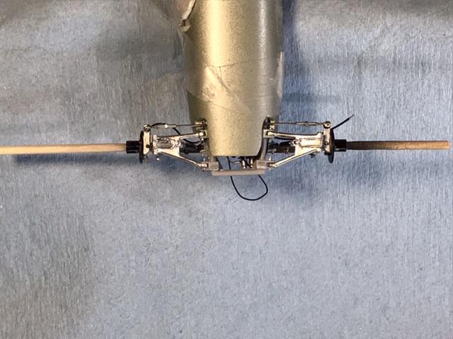
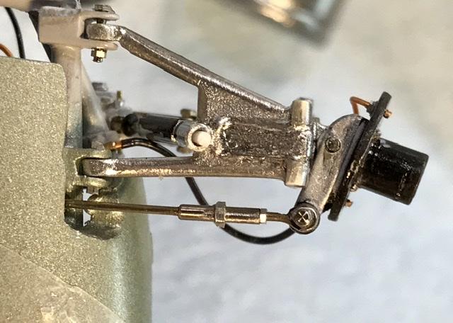
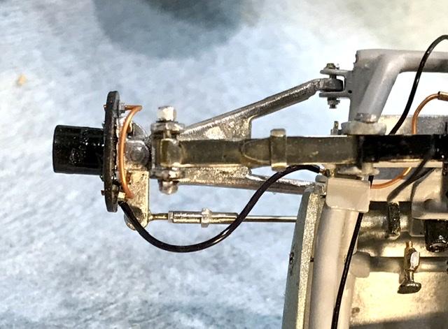
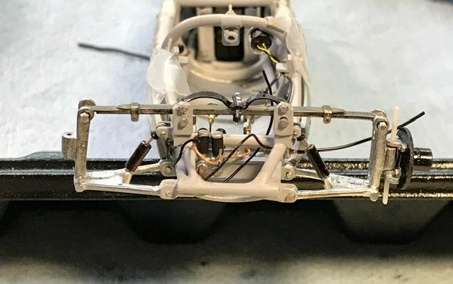
The crowded engine compartment and transaxle detail is fighting me - misplacing small parts and measurement errors on others - so I retreated to the front of the frame to attach some suspension members. Using resin printed bolts (those Russian accessories) and bolts from RB motion - whatever works ... the nickel silver springs will really stand out ...