absmiami
-
Posts
4,779 -
Joined
-
Last visited
Content Type
Profiles
Forums
Events
Gallery
Everything posted by absmiami
-
 Yup. Like that low shot. A lot ...
 -
What do you use to do the acid etch. ? Good point about the brightness of the hardware ...
-
And thanks ...
-
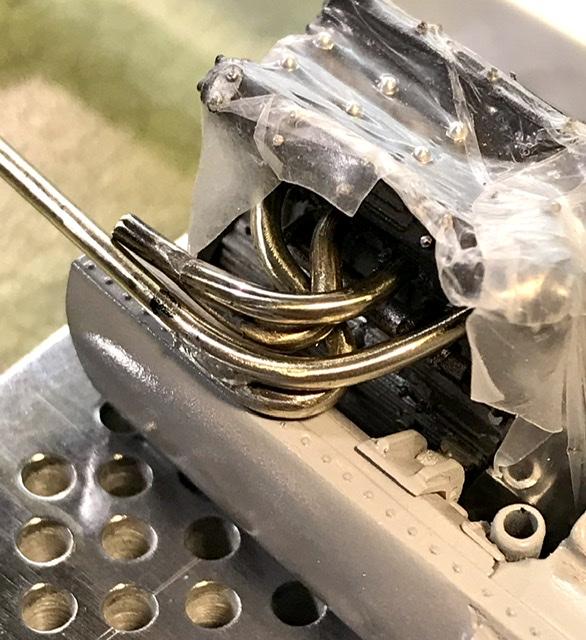
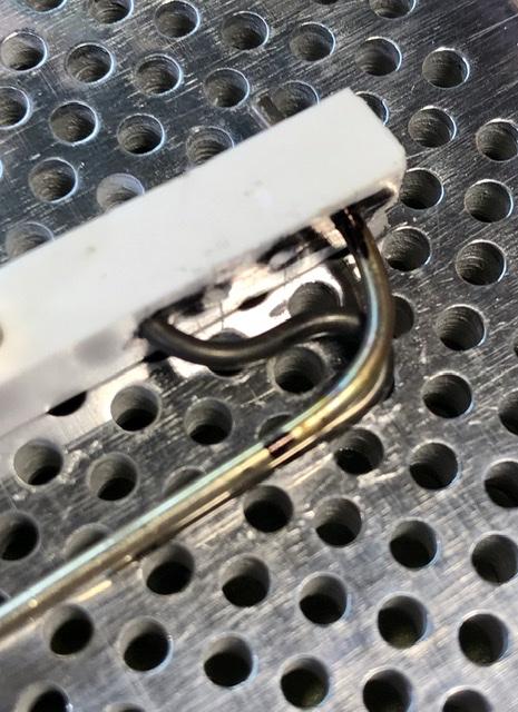
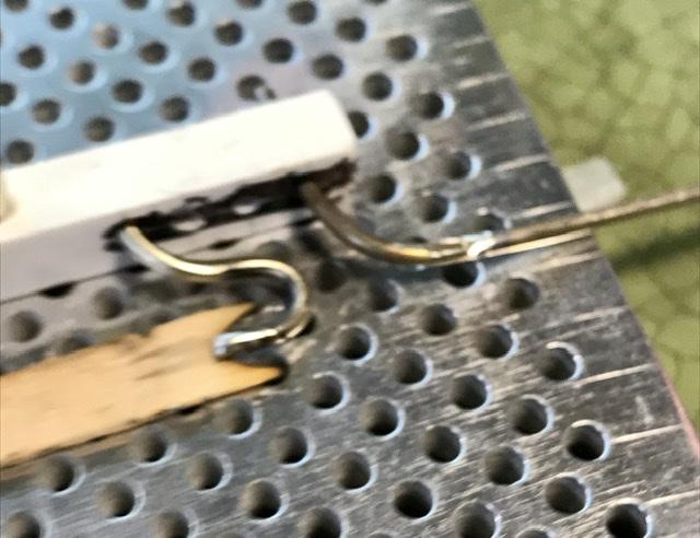
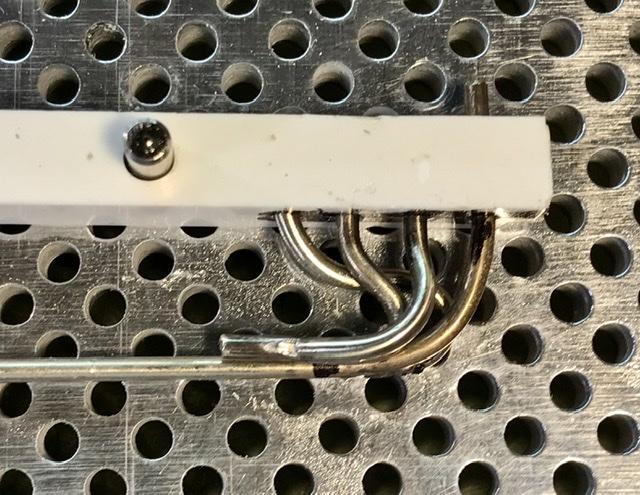
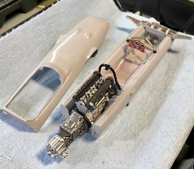
Getting there. Will need a few more Small bends And then the collector pipes - which have to clear the side of the engine cover. Oops - still have to make that ...

-
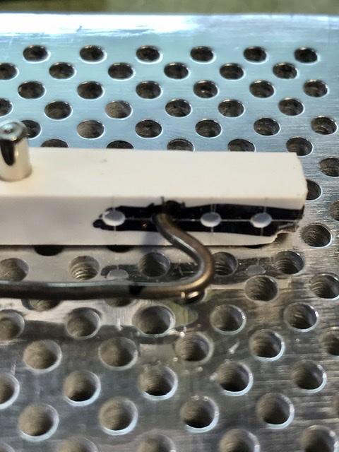
And some more ...
-
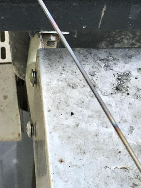
heat and bend ... repeat ...
-
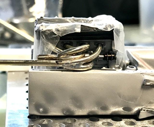
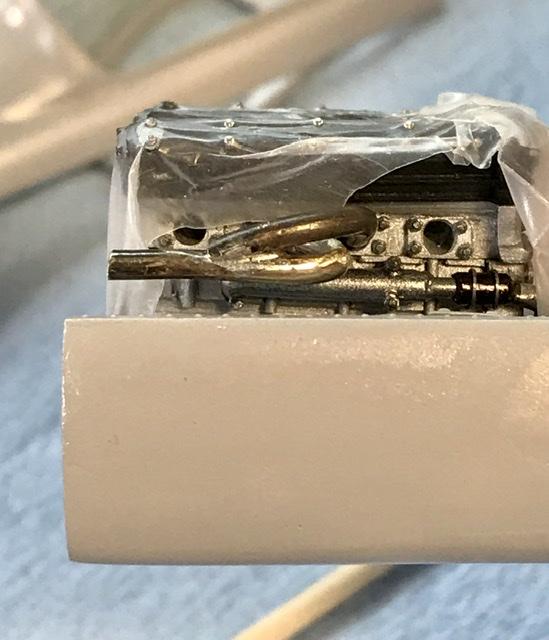
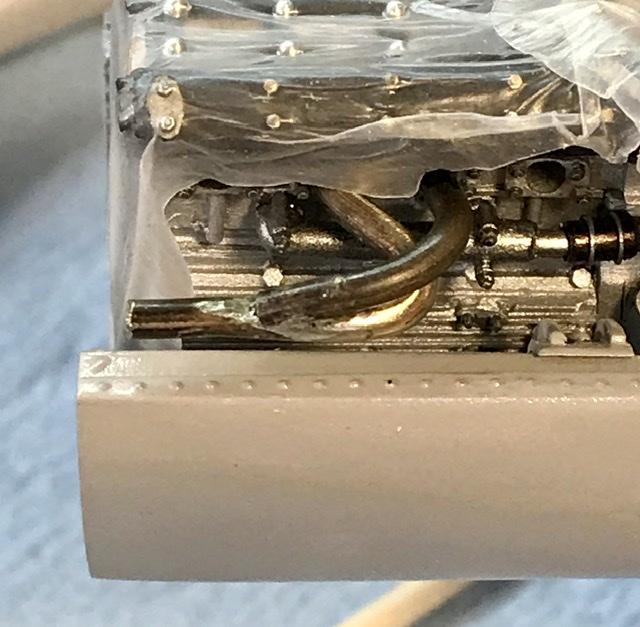
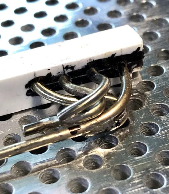
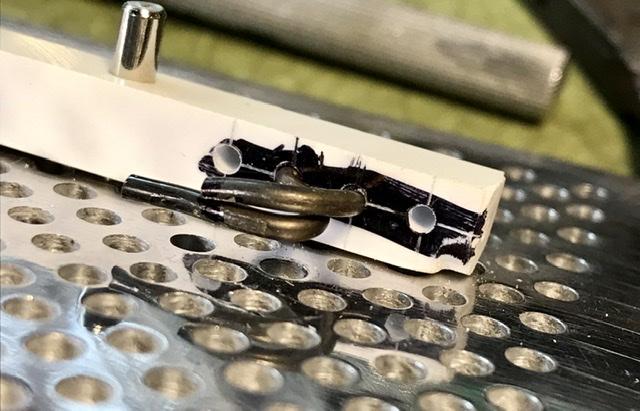
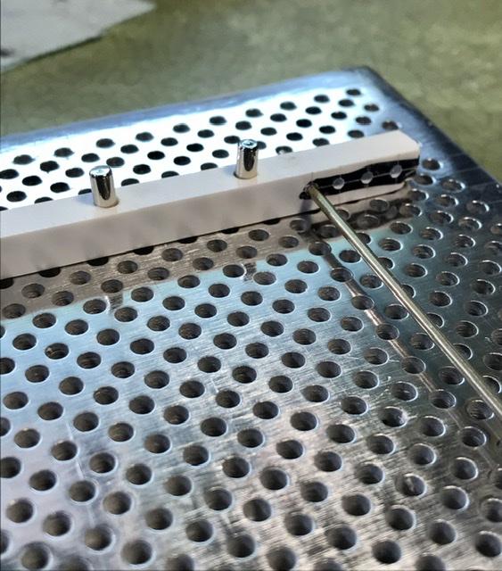
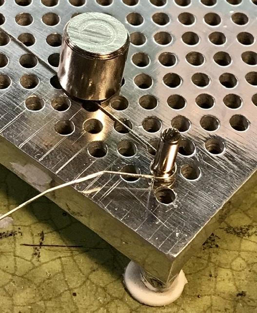
Now to the exhaust pipes. 1 & 4 and 2 & 3 join in collectors and end in a single pipe. Using nickel silver rod. .062. This is probably slightly under scale. But .070 will not fit well into the cylinder head. So this is a scale casualty but not a terrible one. Set up a jig on the beaders’ tool Plate that Randy D used for the exhausts on his bonkers Porsche engine ... speaking of bonkers ... don’t miss the Cosworth WIP ...
-
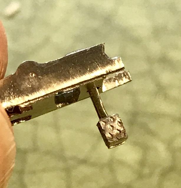
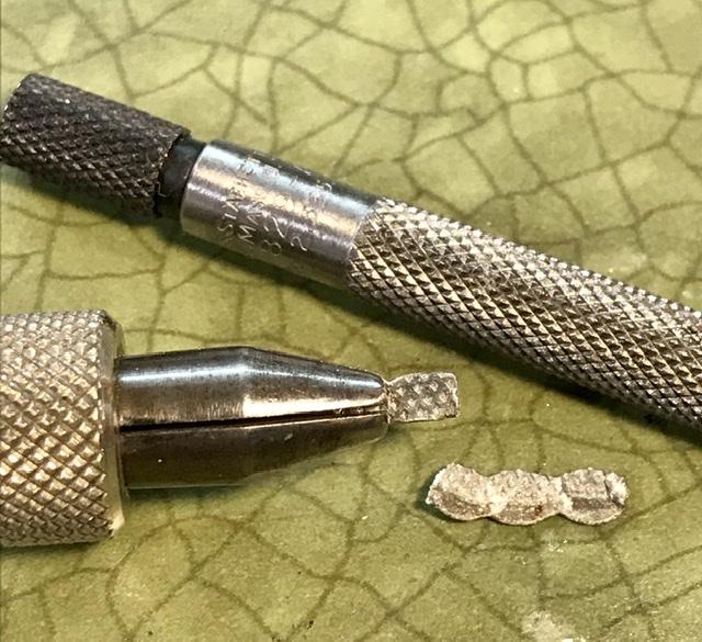
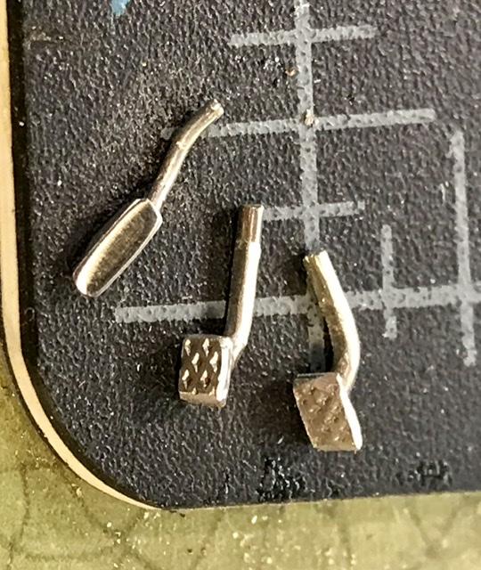
The pedals hang down from this part. The clutch and brake are made from smashed tin solder with a pliers - then I rolled a diamond pattern onto the surface and then cut and shaped and glued this onto a pedal bracket made from nickel silver
-
So. As long as I am breaking things .... might as well show you the broken halves of the rocker arm bulkhead ... this is a lovely kit part - I messed around with it so much that it finally broke in half ... fortuitously, the part(s) are sandwiched between two thin supports so the final installation will look fine...
-
1/8 Ford Cosworth DFV engine
absmiami replied to mad mike's topic in WIP: Other Racing: Road Racing, Land Speed Racers
And yes. There is some lovely red goop seeping out of the transaxle. Can even see it on my I phone ... -
1/8 Ford Cosworth DFV engine
absmiami replied to mad mike's topic in WIP: Other Racing: Road Racing, Land Speed Racers
Oh no .... -
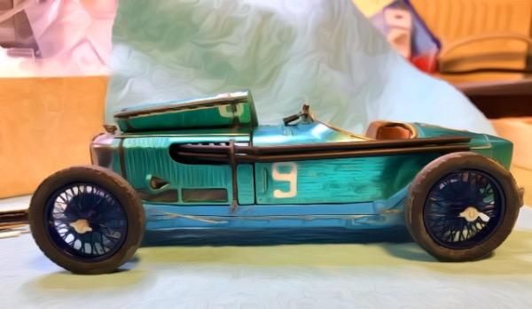
'Blue Bird' 1935 1:18 scale
absmiami replied to FURBALL's topic in WIP: Other Racing: Road Racing, Land Speed Racers
Well. This is cool ... what is the length of the bluebird in 1/18 th ??? -
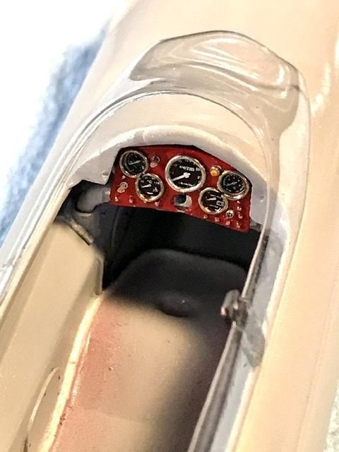
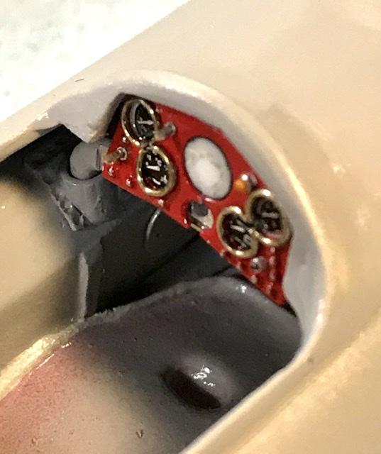
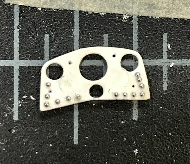
Bezel for tach made fr .015 nickel silver ... glued with Tamiya clear ... dash is almost done ...
-
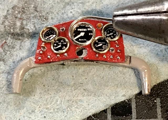
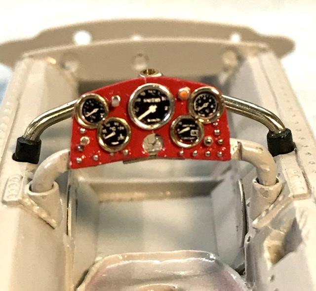
Taking shape ... the left / right halves are glued to the brace - the instr gauge housings on the back side are then glued and will / should / probably hold everything together ... added ignition and fuel pump switches plus oil temp light and starter button. Pretty crowded. Next is the tach and the last detail on the back side ... this process reminds me why I don’t build 43rd scale kits ...
-
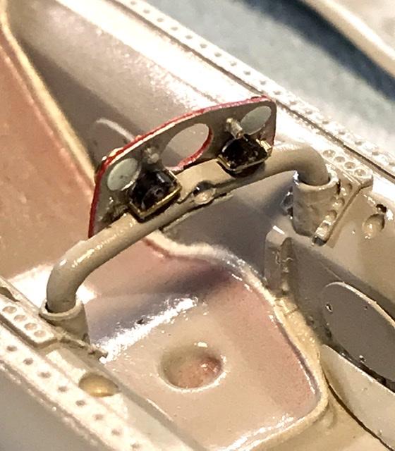
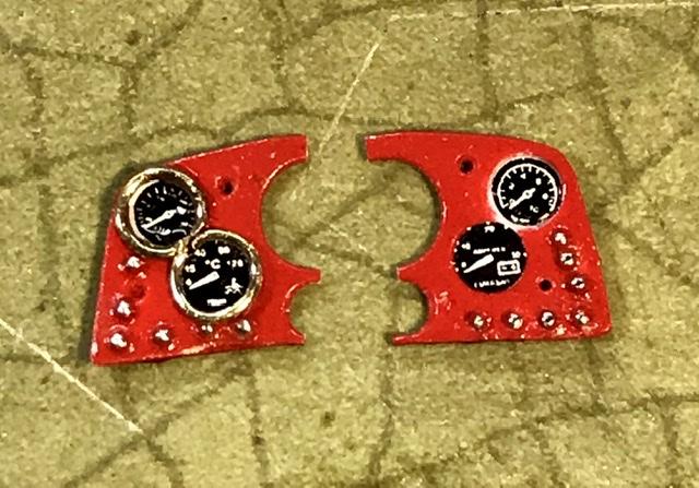
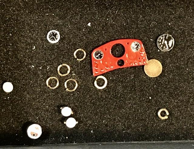
The modeling gods had some fun at my expense tonite ... not surprised ... the thin plastic panel required a lot of handling. And sure enough - it broke in two while I was installing the gauge bezels ... should have made the panel in aluminum or brass ... but I can still use this - I think - when left and right are glued to the brace and the other parts are attached - I think it will look fine ... to be continued ...
-
Revell 1/24th scale Jaguar E-Type FHC: Test Shots
absmiami replied to Justin Porter's topic in Car Kit News & Reviews
Long story short. - looks really good. And it’s 24 th scale ... at least as good as the Heller and probably better ... whose going to be the first to build one with opening doors and rear hatch ??? Might be time to splurge on that wonder cutter ? -
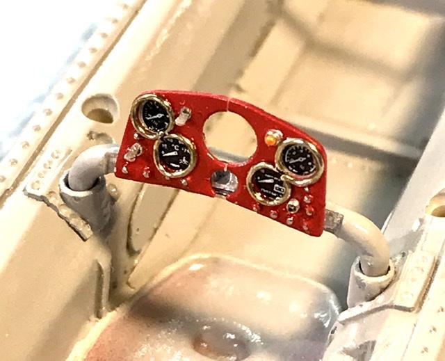
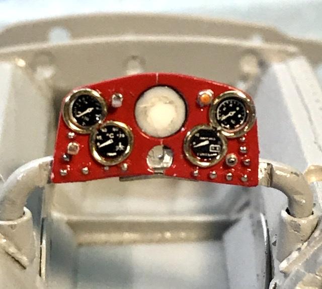
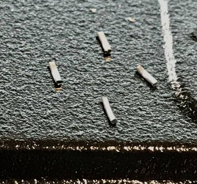
Gauge bevels made from .013 nickel Wire bent around a file to make that curly Q. Which is cut into rings and filed flat in the bottom side . ... this should work ...
-
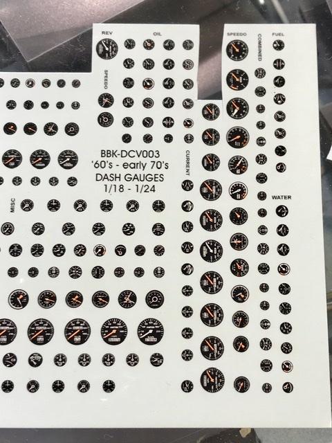
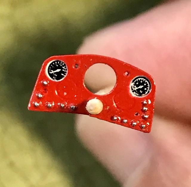
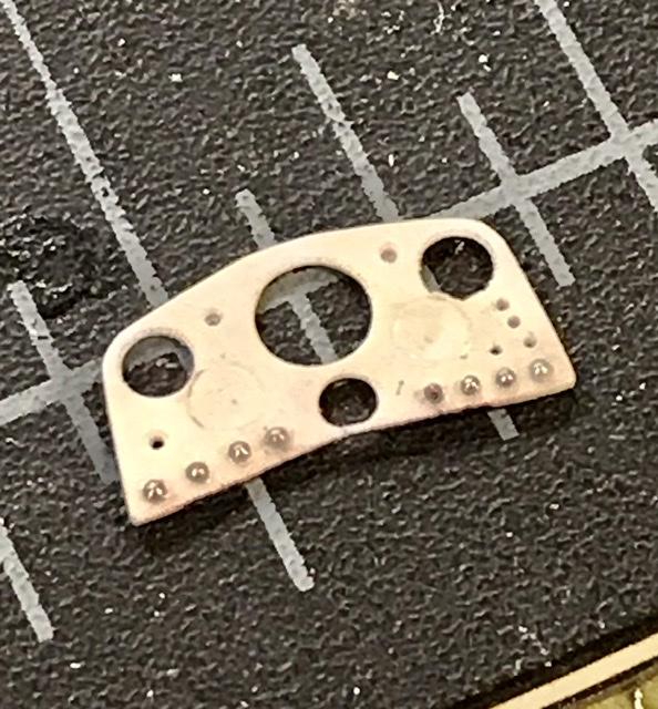
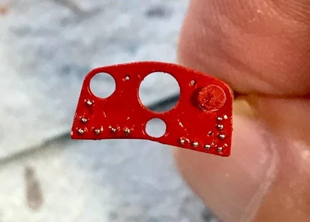
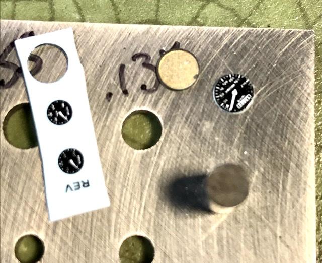
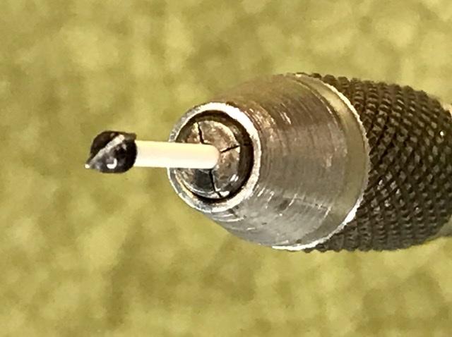
I the instr panel is fighting me ... I’m fighting it back ... the rivets were difficult to install. Would have been smarter to have used a rivet decal and picked out the silver after painting. Anyway ... punching out and installing BBK gauges after a coat of Tamiya red. With some flat additive ...
-
Yup. It’s a tank. Gotta revu my doug Nye stuff. The 159 added a bunch of things not used on the 158 ... I’ll figure it out ...
-
Not that you asked .... but a clear red vinyl LP would match the base color of the body rather nicely ...
-
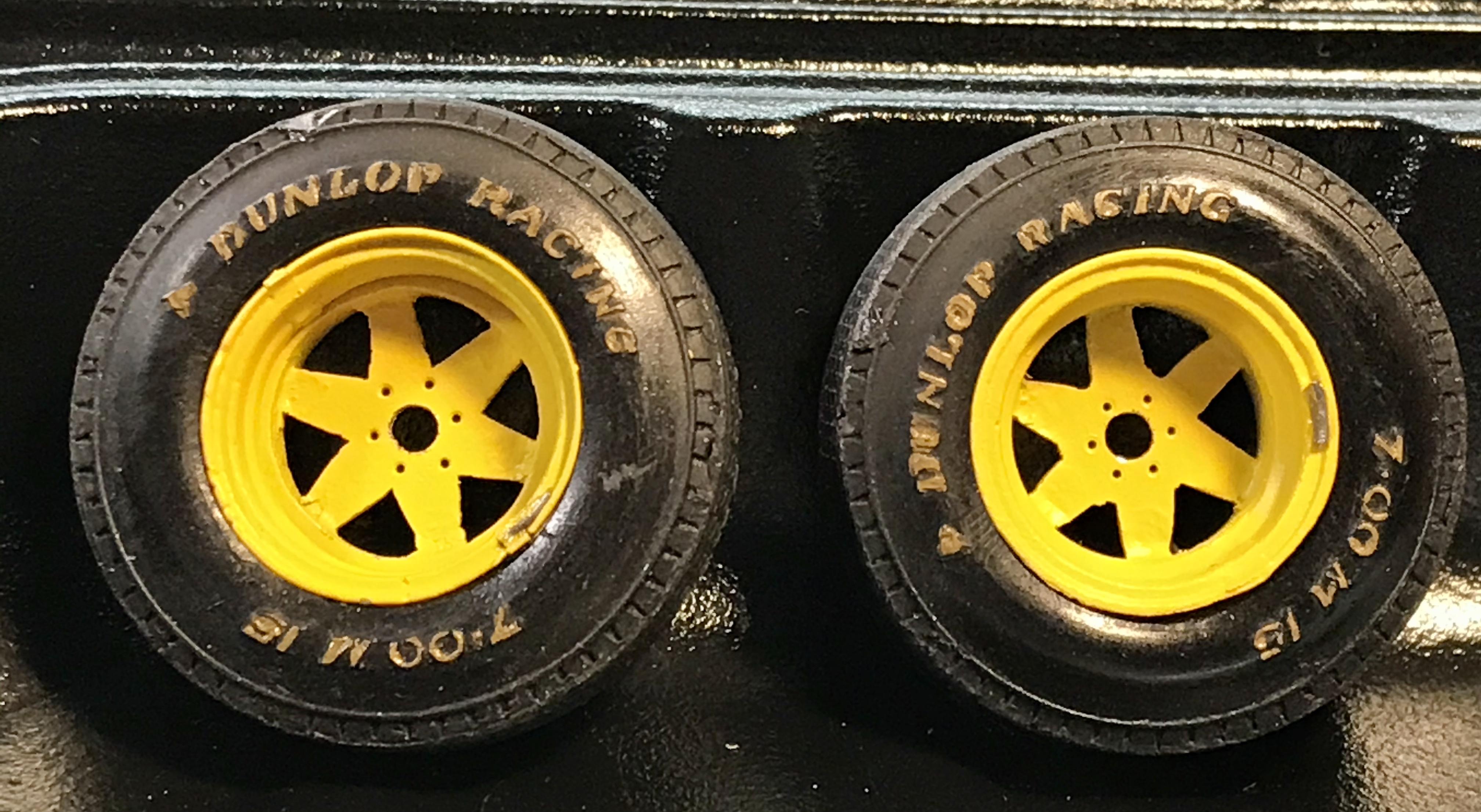
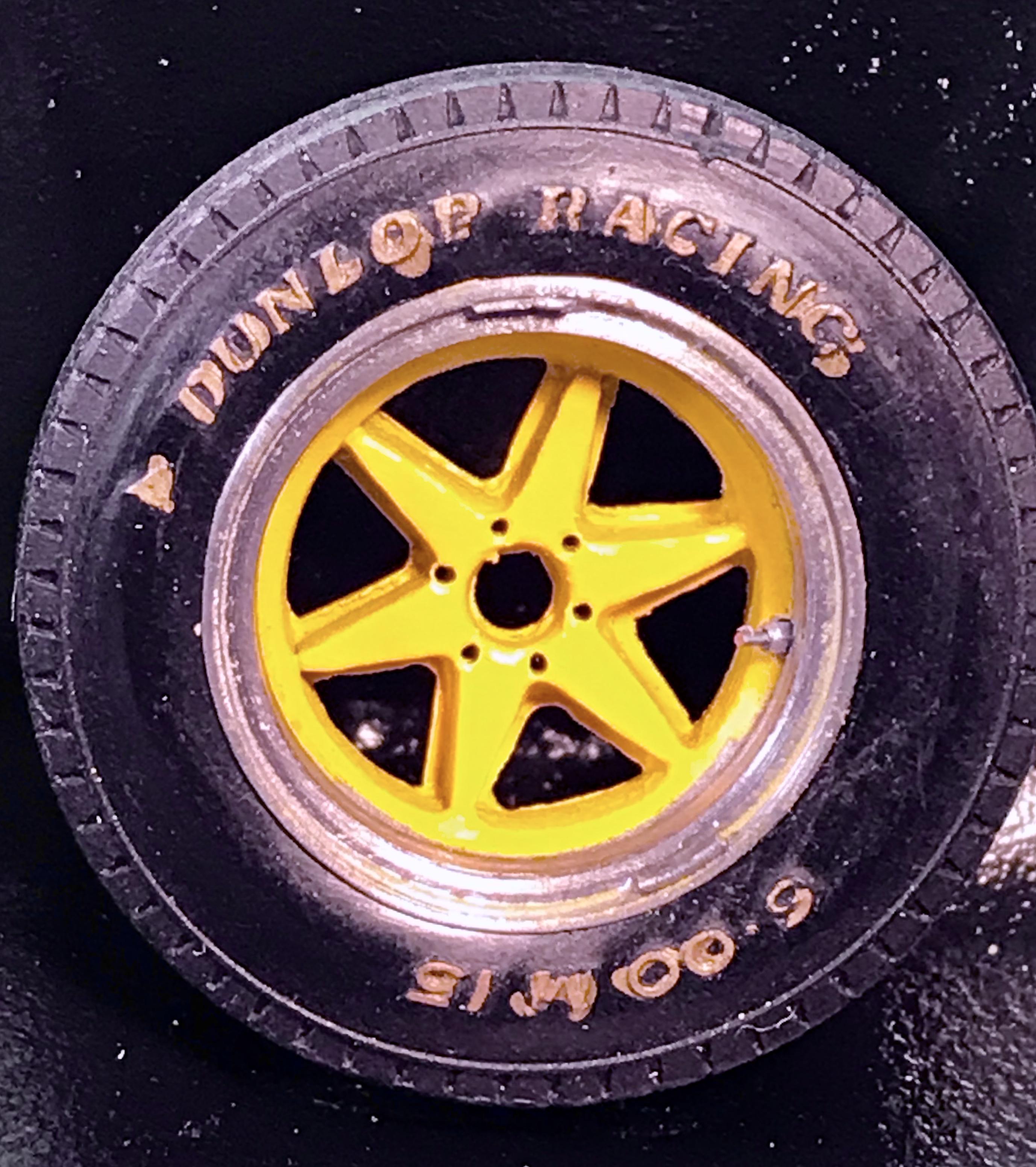
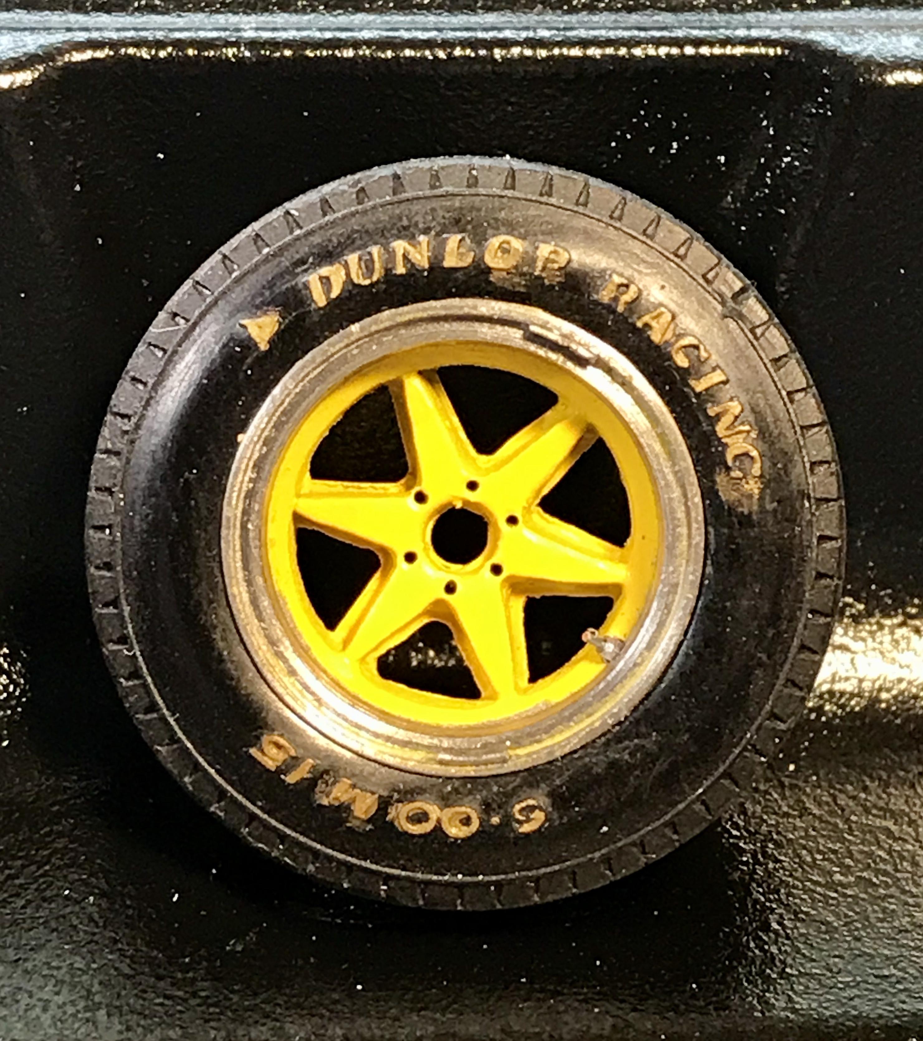
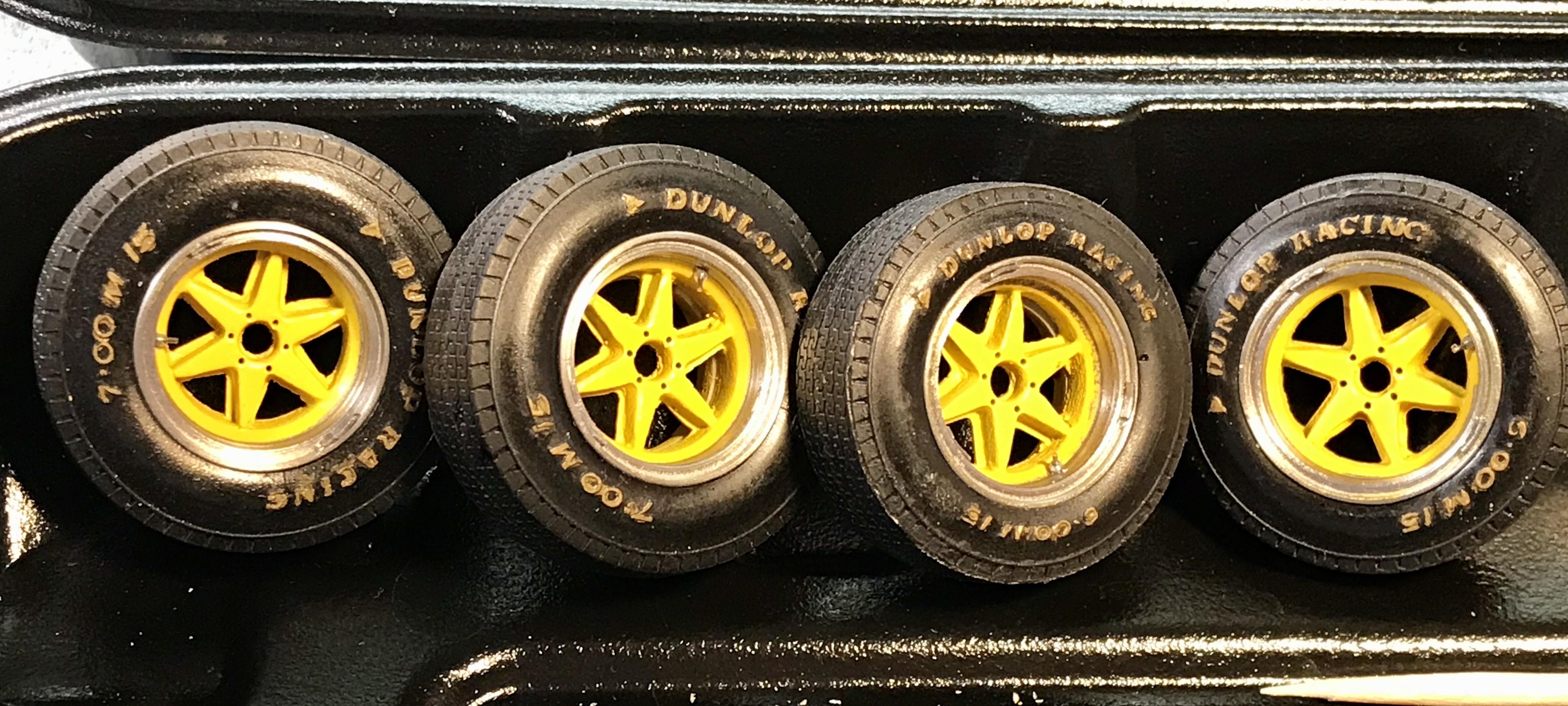
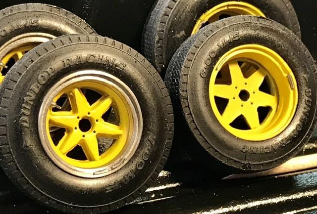
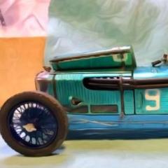
The few contemporary photos from the Tasman campaign suggest that the tire markings were painted gold. Again not certain but taking a shot with an ink based Fine point gold sharpie. This is some hold your breath - not after a beer Modeling and yes magnified - most of this build has been done with an opti-visor. Which is now a more important tool than my Xacto knife .... the excess ink is mostly removed with the point of the xacto ...
-
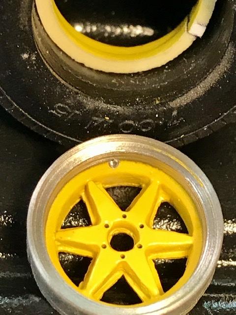
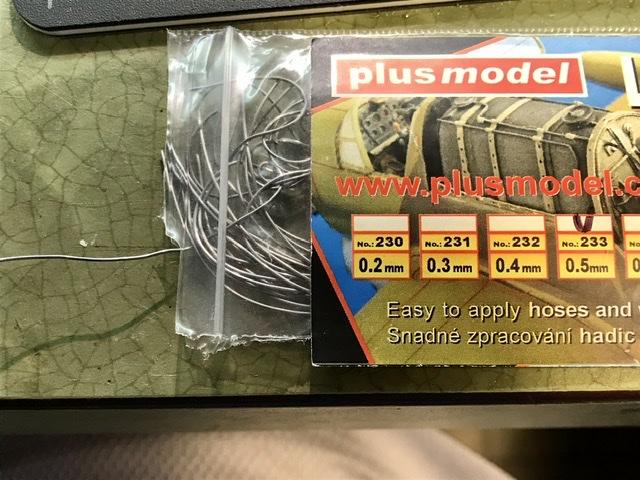
Also did some work on the wheels and tires while waiting out our last ?? ?? Tropical storm of the season to pass ... tire valves made from RB motion fuel line connections and steel wire. And wheel balance weights Made from soft tin wire ... pondering the wheel nuts . .. not certain yet ...
-
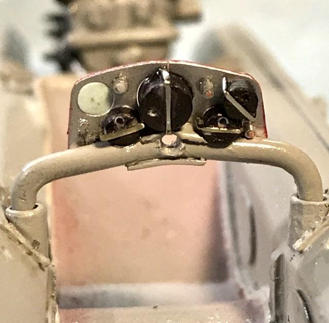
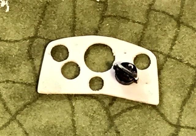
The panel is exposed. So I have to show some of the detail on the back side. Making the instr housings from plastic tube and rod and straps made from .013 nickel Wire bent, sanded, and glued to the plastic housing
-
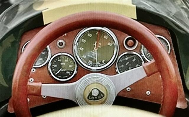
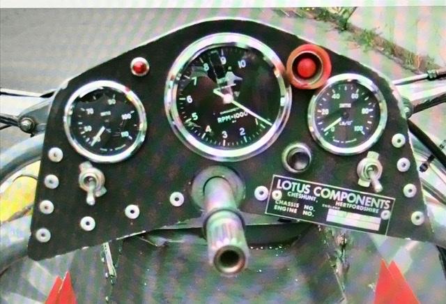
The panel on the Team Lotus restored 32b is here. There are no good pictures that I have seen of the panel as raced in the Tasman series. But I’m pretty sure that it was different than the restored panel. - so I’ll make some changes based upon what I have seen in contemporary shots of Lotus formula cars in ‘64 and ‘65 .
-
Back to the dash before making the exhaust pipes .. the instrument panel on the 32b is based upon the Lotus 32 panel. A restored one is pictured here ...