BK9300
-
Posts
1,986 -
Joined
-
Last visited
Content Type
Profiles
Forums
Events
Gallery
Everything posted by BK9300
-

Western Star 4900 FA plow truck
BK9300 replied to BK9300's topic in WIP: Model Trucks: Big Rigs and Heavy Equipment
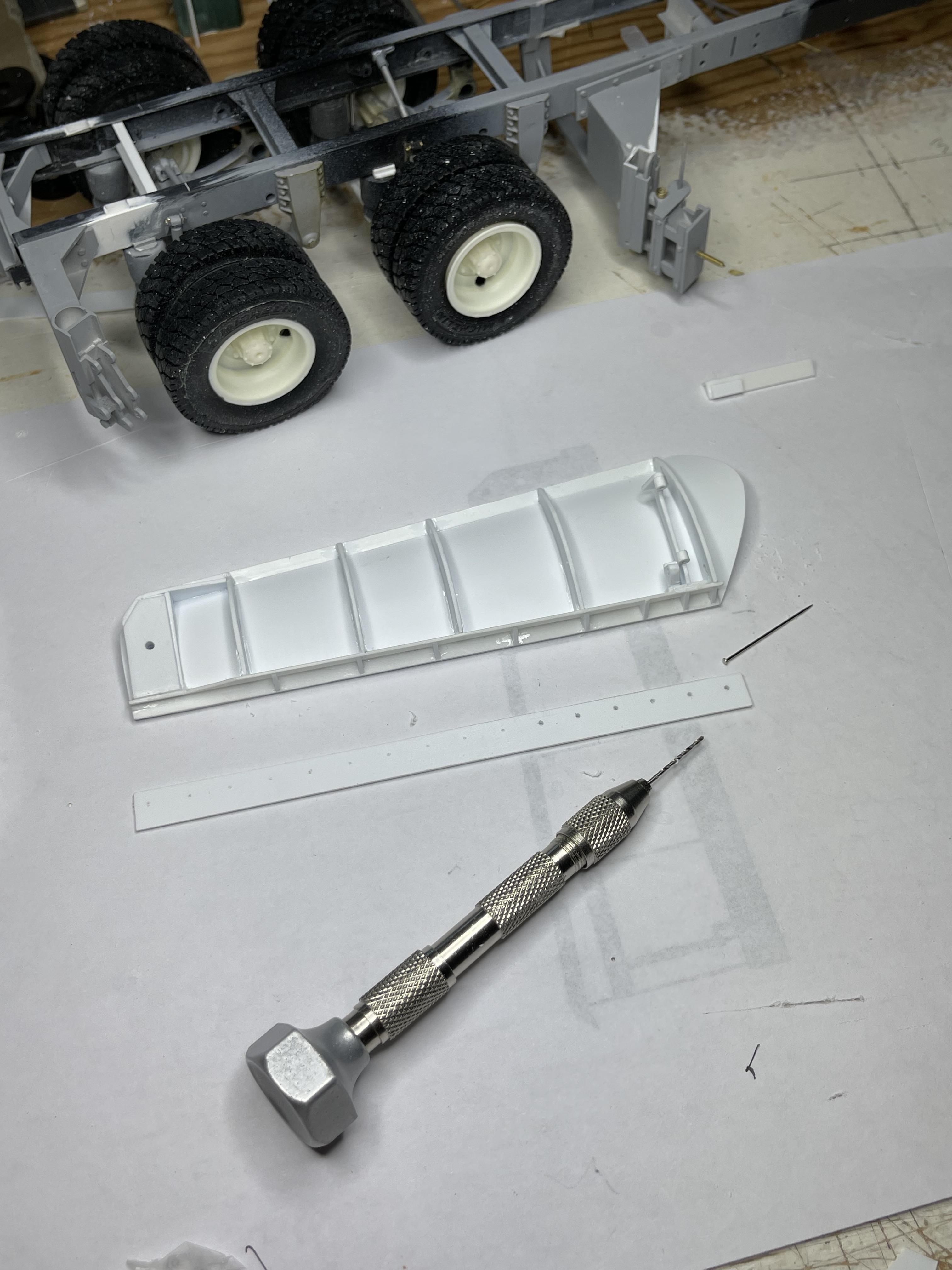
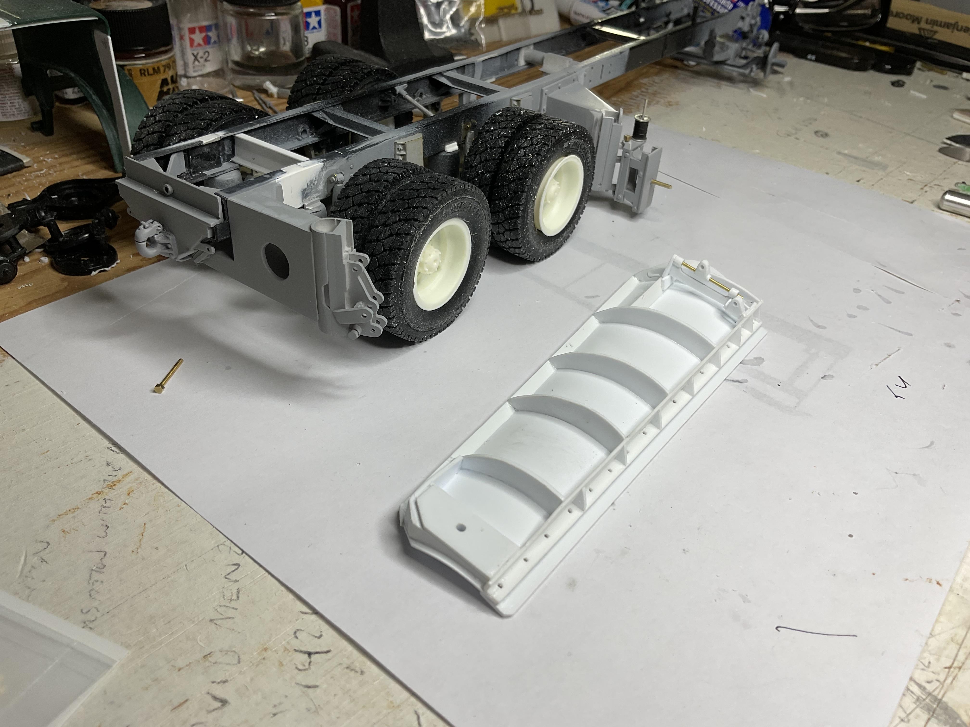
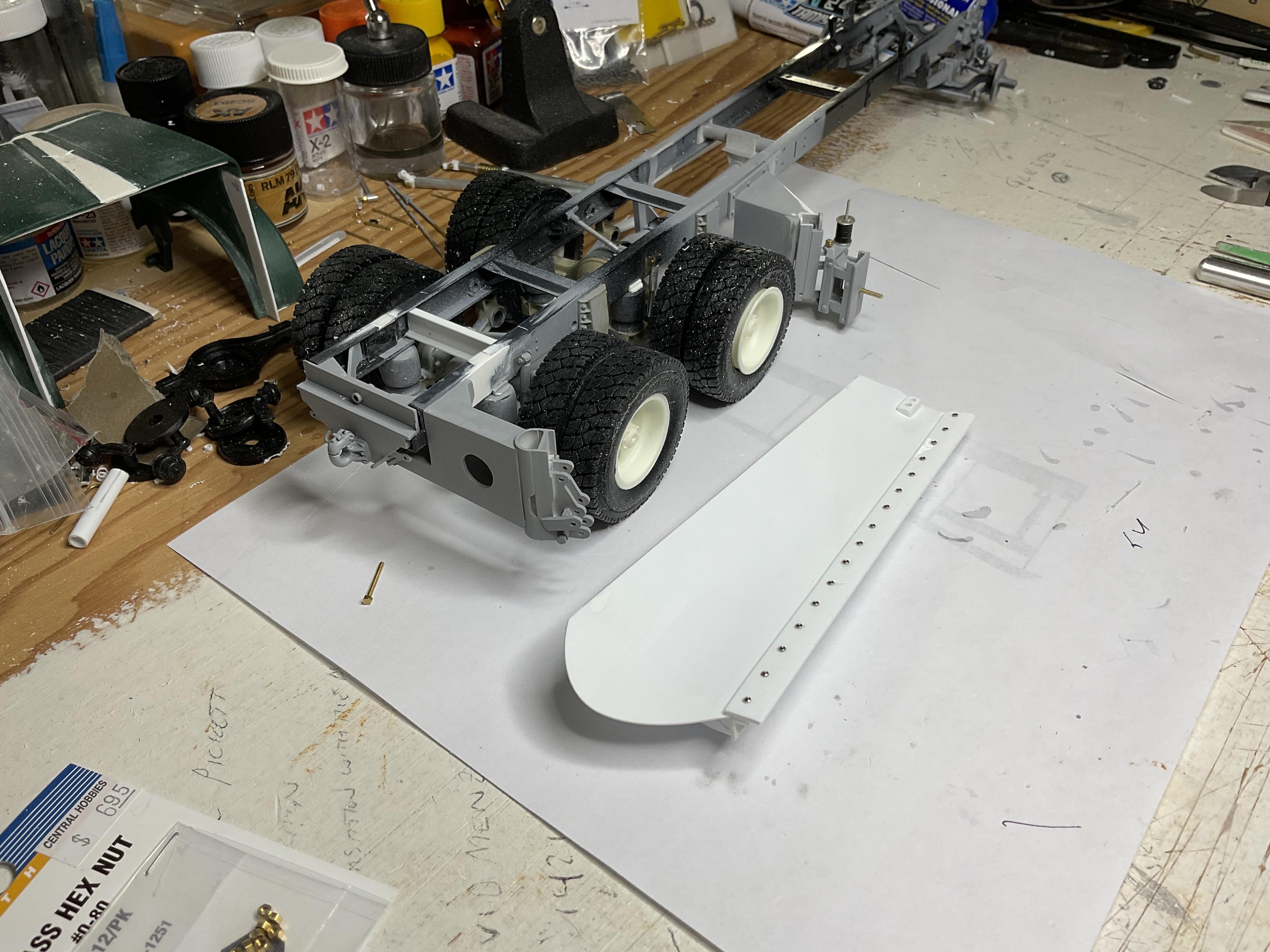
So far, I’ve been lucky to find some version of the real truck’s equipment online (like Tenco’s Wear Parts book for the wing plow mounts), plus using my own measurements of real truck; for the underbody, no such luck with manuals, so measuring the real one was the only way to go; the curved surface of the model's moldboard was bent along “brake” lines using a steel ruler to simulate the real life machine brake lines; tried to avoid getting whipped again making the plow's lift cylinder (failed!) more patterns and cutting - 30 plus pieces - good thing for extra readers and magnifying desk lamp! pattern for surface of plow moldboard - trying to lay out the machine brake lines angle iron backbone of the moldboard and pivot brackets that plow raises and lowers around intake portion of the "skin" attached these (adjustable) brackets are the frame mounts that the plow's vertical support pins attach to Exhaust half of "skin" formed and attached resin nuts and washers from A & N attaching blade to moldboard support pins on plow and frame brackets for pins - pins is probably not a good term - on real truck these are 2 1/2 inch solid steel lengths of rod this cylinder raises and lowers the plow - end of hydraulic cylinder moves inside spring and slotted support - another anti-kickback dampener lift cylinder attached to its frame mounting bracket on left better view of cylinder frame mounting bracket - cylinder pivots slightly in this bracket as the plow is raised and lowered mockup of underbody plow - intake side - raised and lowered plow "exhaust" or outlet side - raised and lowered (had to add front tires to see if plow height was ok) a lot of hours can pass by doing this hobby - great therapy - more later!
-
Farm Floater Truck 1/24th scale
BK9300 replied to Randy D's topic in WIP: Model Trucks: Big Rigs and Heavy Equipment
An amazing amount of detail in your engine - very inspirational! -
I think we have the sluggish forum problems solved
BK9300 replied to Dave Ambrose's topic in How To Use This Board
Great job, Dave sure is faster than this morning! -
1955 Ford F-100 Street Rod
BK9300 replied to Zippi's topic in WIP: Model Trucks: Pickups, Vans, SUVs, Light Commercial
Hi Bob - stance is looking good! Making the vision come to life can test one’s patience. -
Western Star 4900 FA plow truck
BK9300 replied to BK9300's topic in WIP: Model Trucks: Big Rigs and Heavy Equipment
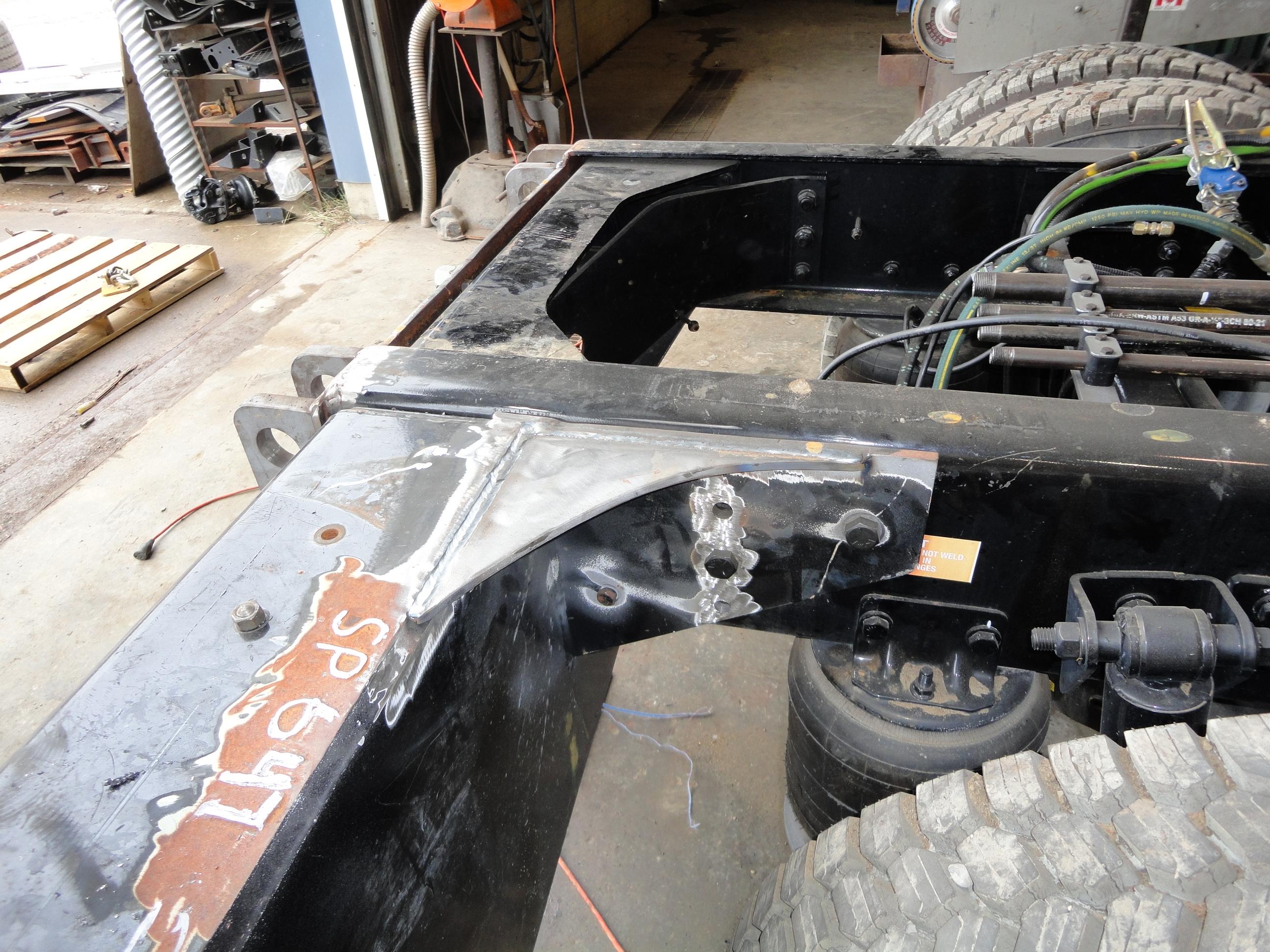
Thanks, Gary. Lots of pics and measurements. I'm guessing about a third of my build time has been spent looking at all the photos, and on the web, figuring out how all the pieces work together. Was also fortunate to have had access, over the years, to the shops where our trucks were built and talked with guys making all the real pieces come together.
-
Hello everyone, from North Vancouver
BK9300 replied to BK9300's topic in Welcome! Introduce Yourself
Mathias, thanks for the welcome! -
Johnson & Towers DDA
BK9300 replied to Scott Eriksen's topic in WIP: Model Trucks: Pickups, Vans, SUVs, Light Commercial
A little crane would very typical for these service trucks. If its an out of the box build, who makes the truck body? Looks great so far! -
IH Transtar 4300 converted to a 4200
BK9300 replied to k100's topic in WIP: Model Trucks: Big Rigs and Heavy Equipment
Love all the metal - u-bolts, rad supports, shocks - great detail! -
Building the Streamliner from the AMT Double Dragster kit
BK9300 replied to OldNYJim's topic in WIP: Drag Racing Models
Nice work, Jim. Your custom brass work really makes the details pop. I think I'd burn the place down trying to do it! -
I needed another project....T800
BK9300 replied to gotnitro?'s topic in WIP: Model Trucks: Big Rigs and Heavy Equipment
Hi Jeff - going to be a big trailer when its finished - great detailing going into this. Where did you get the laser cut frame pieces you mentioned earlier in your thread? -
Terrific build - these trucks are really impressive in person (as well as the rig moving truck on the trailer in your first pic). Back in the day, used to live in Fort St. John, BC and saw trucks like this owned by L.A.N.D. Transport on the road all the time. Very good job!
-
Western Star 4900 FA plow truck
BK9300 replied to BK9300's topic in WIP: Model Trucks: Big Rigs and Heavy Equipment
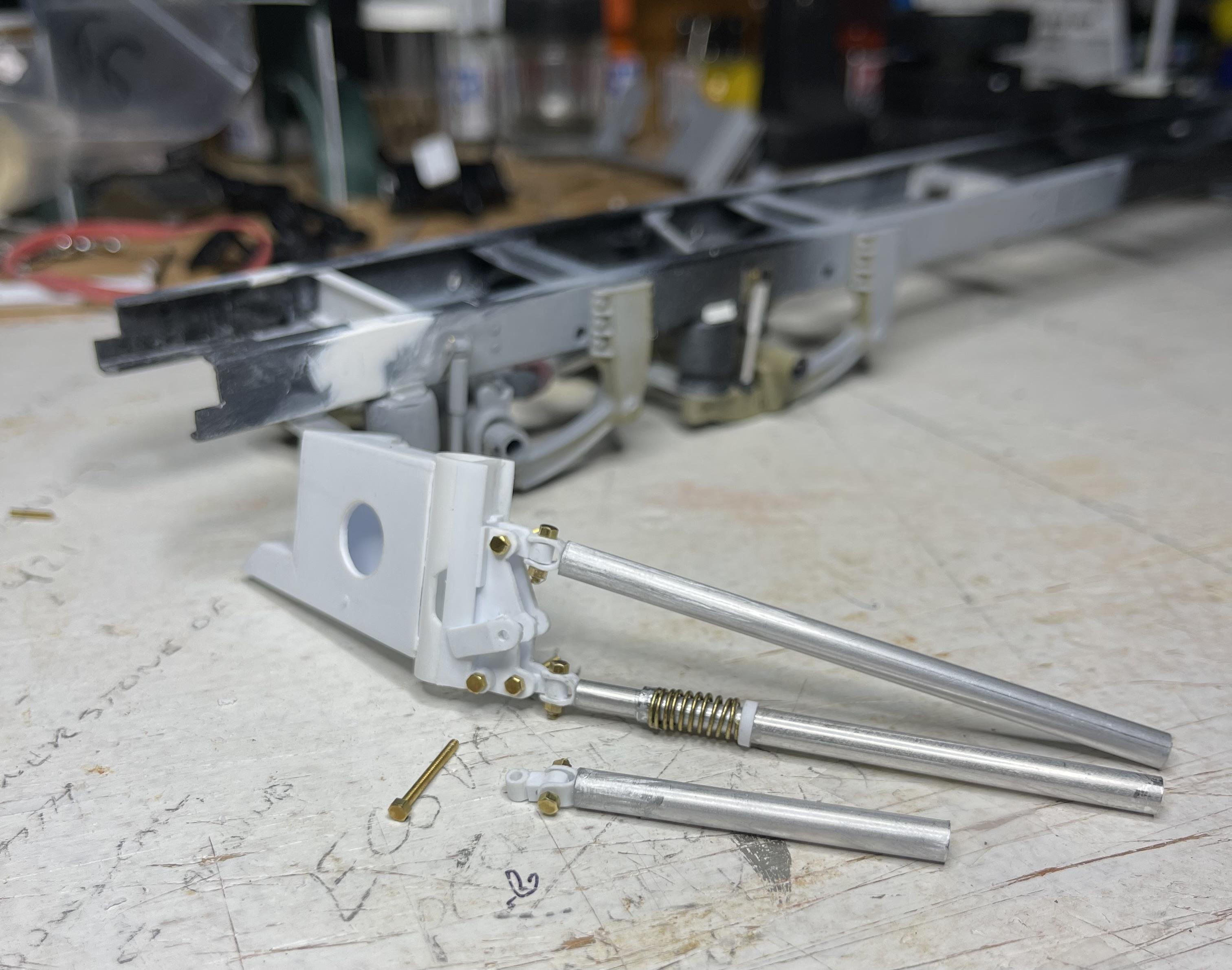
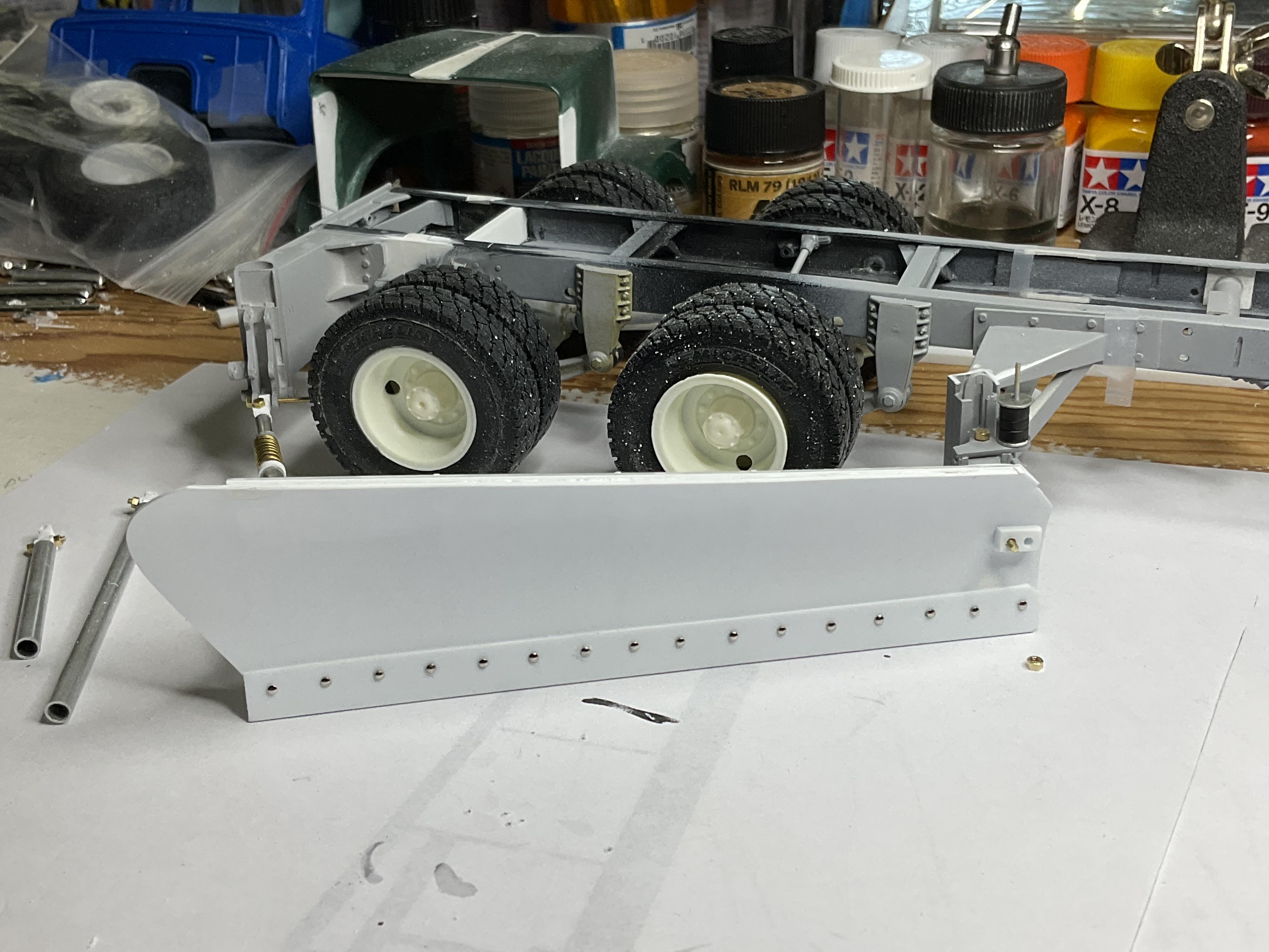
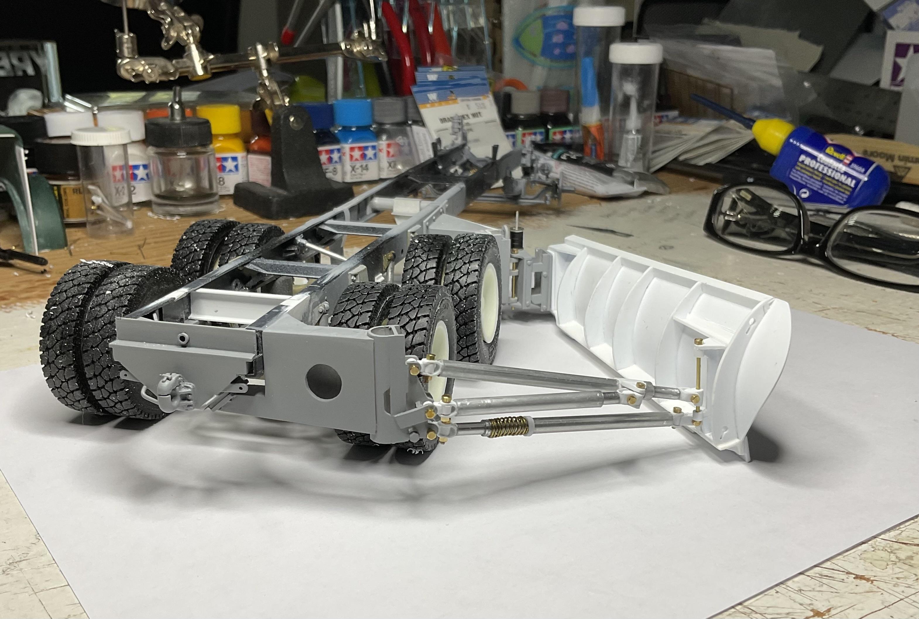
Been doing some priming of parts along the way – nothing like primer to show all the spots that still need work! I started on the wing plow itself – cut the pattern pieces and assembled them over a couple days, to keep the plow frame straight; in between, fabricated the wing plow’s support bracket, on the rear frame mount, for the two lift arms and hydraulic lift cylinder to mount to; added some bolt head detail where the plow mount attaches to the rear cross member – this unit slides over the end of the frame rail, into final position; worked on the lift arms and lift cylinder using aluminum tubing, more brass bolts/nuts and styrene joints; added tops of dress maker’s pins to front of plow blade (for bolt heads) and A&N nuts on washers to the back of the blade wing plow frame - front of plow is on left side - the rectangular box is reinforced box for the plow to bolt to the front, frame mount finished the lift cylinder's support bracket that is part of the rear frame mount bolt head detail on frame mount, which is now attached to rear crossmember - slips onto frame rail where the black and white pieces meet, for final positioning started work on lift cylinders mostly completed lift cylinder arms (two longer ones) and the hydraulic lift cylinder; lift arm with the spring is another anti-kickback dampener - spring was made from brass wire gripped in drill chuck and wound around tubing - whipped myself pretty good, a couple times, before I got a spring that looked okay! test fitting the lift arms and cylinder "skin" of the moldboard is attached; vertical sliding joint on the right is where lift upper lift arm attaches - the anti-kickback lift arm attaches at the bottom joint; the lift cylinder will attach to the upper lift arm making the plow blade bolt holes and bolt heads (from pins) initial mockups of rear wing plow - reinforced area of blade for bolt attachment to front plow mount still some way to go to get the wing articulating right - just about there! Enough for now - will post some more soon!
-
Western Star 4900 FA plow truck
BK9300 replied to BK9300's topic in WIP: Model Trucks: Big Rigs and Heavy Equipment
Thanks, Gary - so far, so good. I'm going to have trouble with the body work I need to do to widen the WS Alaskan Hauler hood. was never very good with putty at this scale! -
Hello everyone, from North Vancouver
BK9300 replied to BK9300's topic in Welcome! Introduce Yourself
Thanks, Mike, I appreciate the welcome! -
Western Star 4900 FA plow truck
BK9300 replied to BK9300's topic in WIP: Model Trucks: Big Rigs and Heavy Equipment
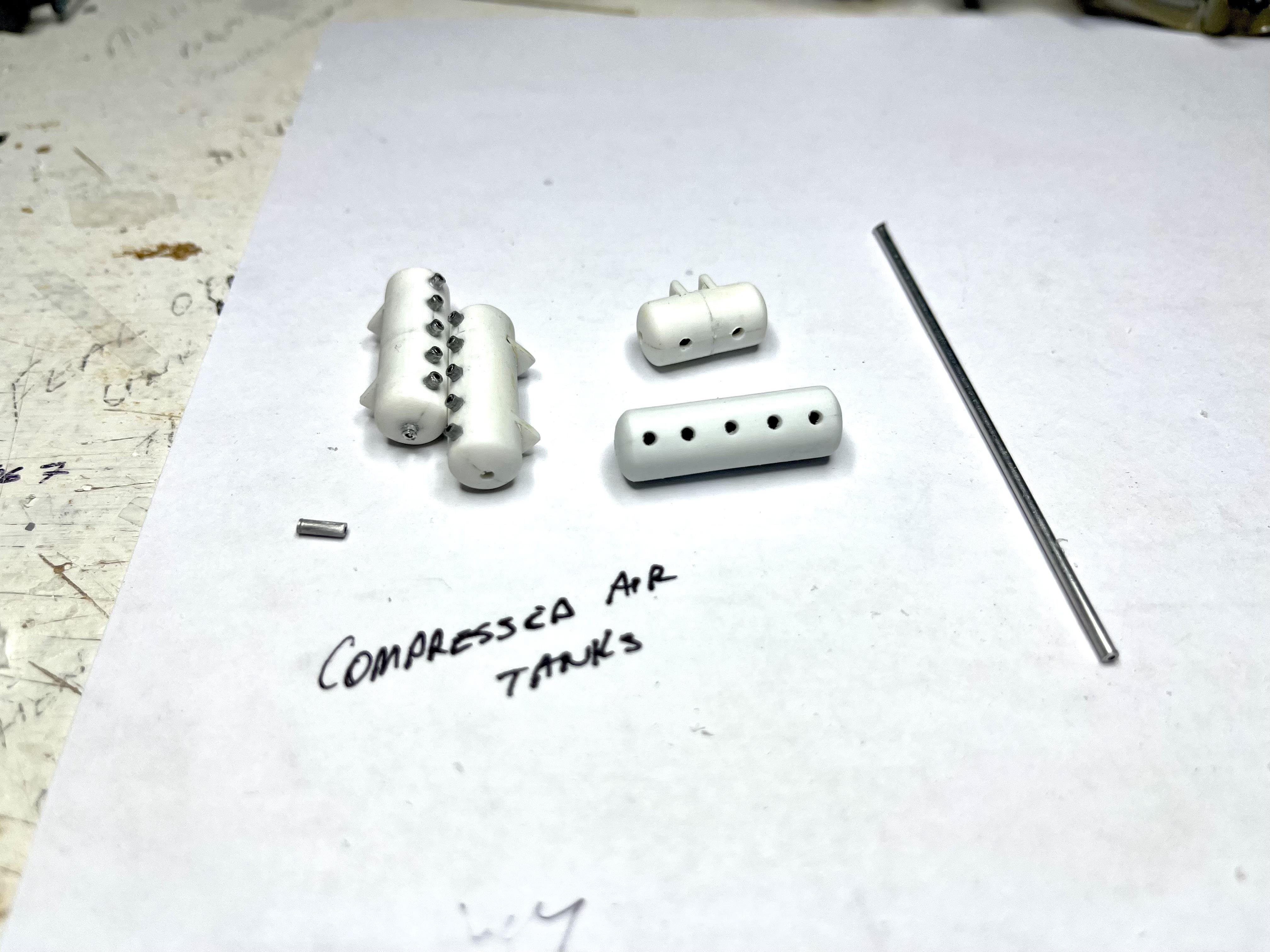
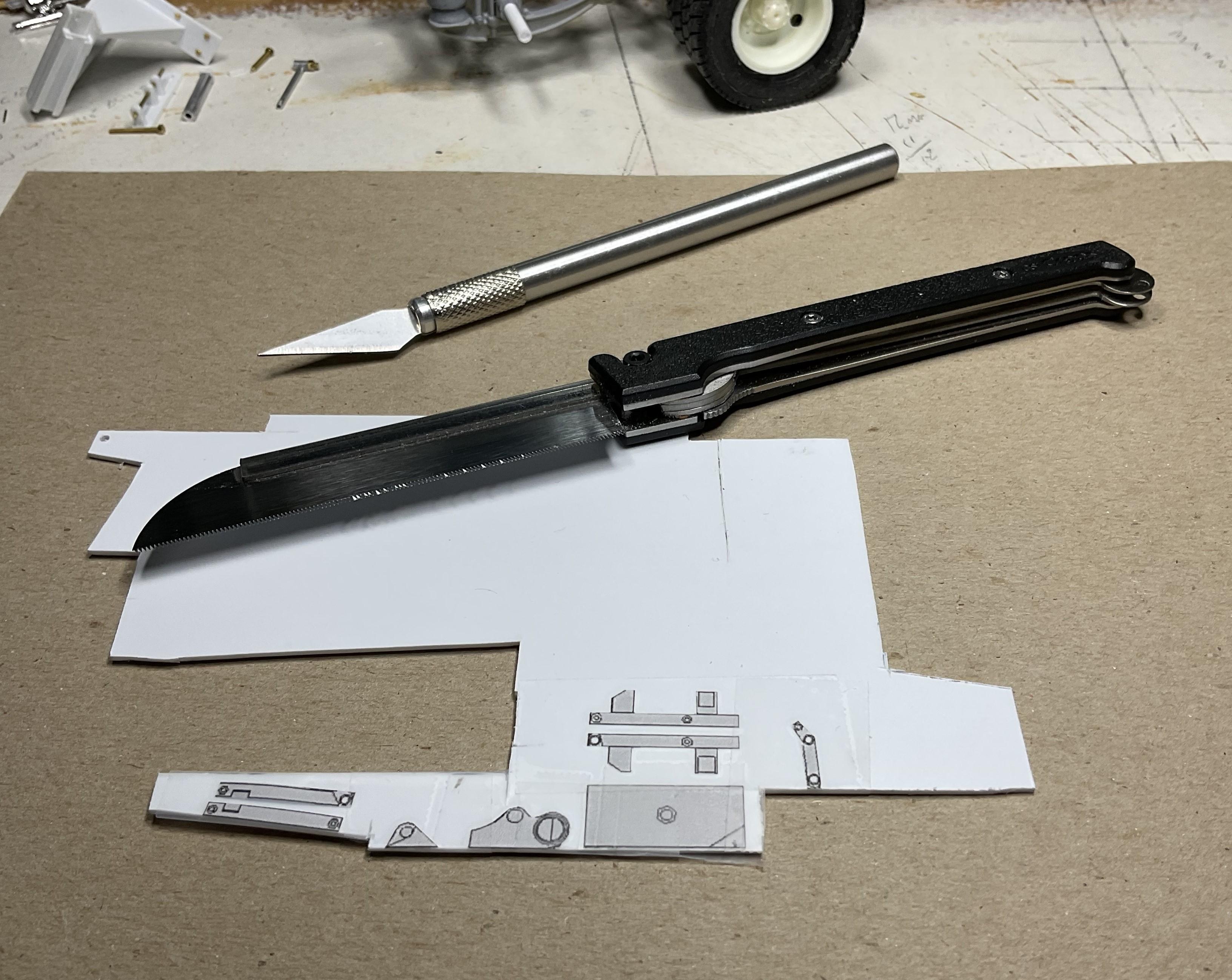
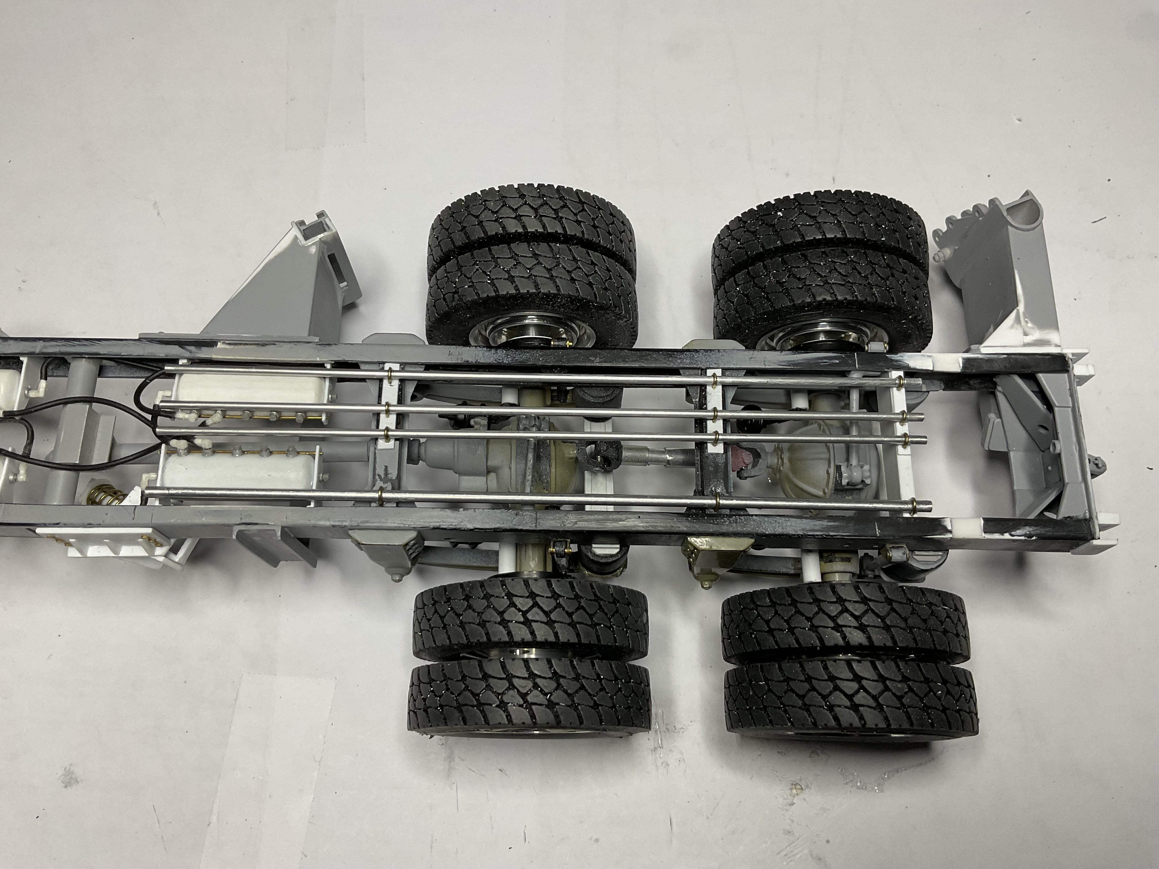
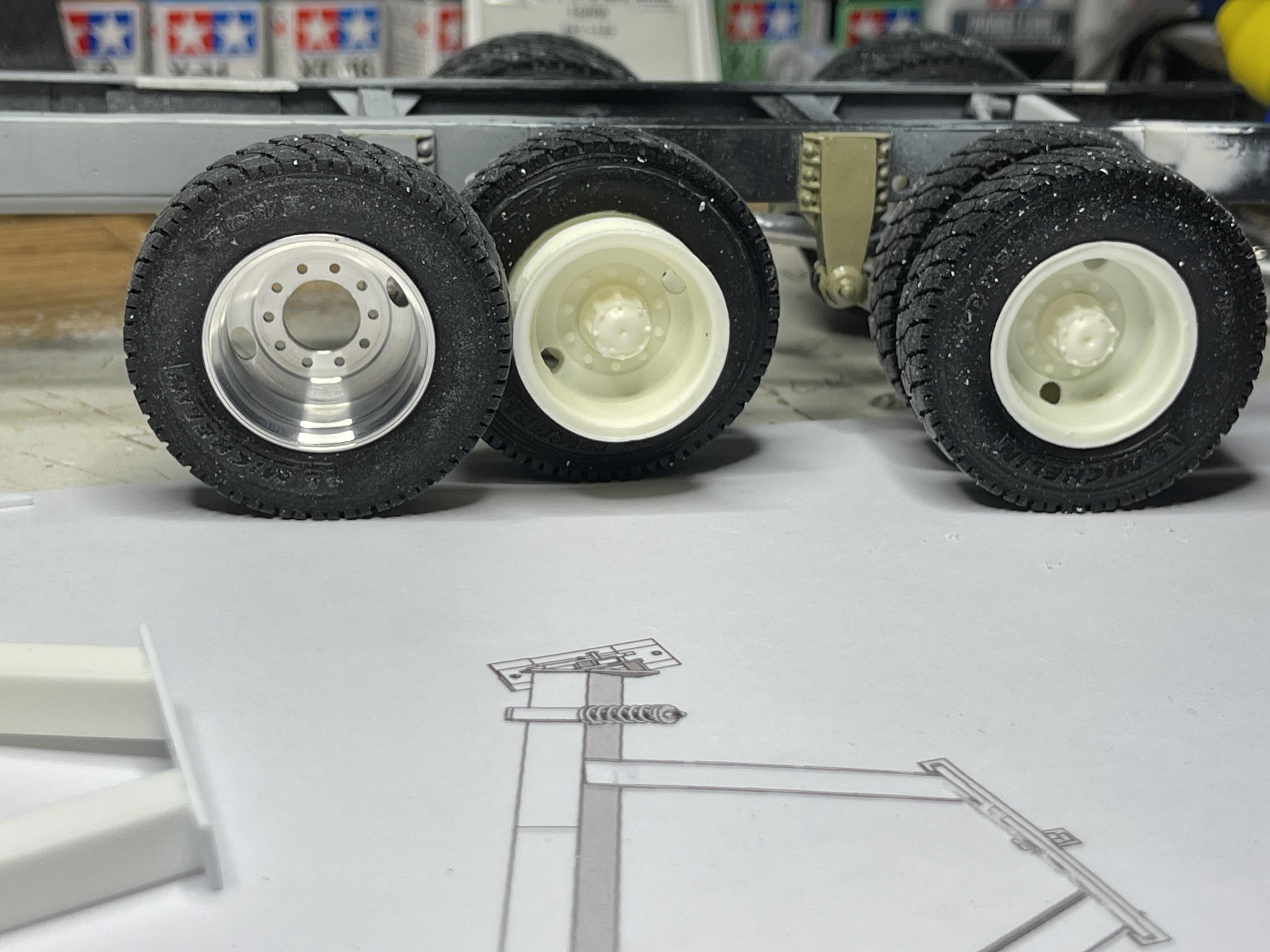
Hope everyone’s having a good summer, staying cool as you can and clear of the fires! I’m going with fewer pics per post in hopes I can get past the moderator’s approval process for new members. I get the reason for the process so maybe shorter posts will get me there quicker! (as all these pics are from last year, I didn’t do all this work in a couple days – I’m at about a month and a half into the build at this point). Threw in a pic of my workspace around that time - lots of "stuff" in the picture and about 1 1/2 square feet to work in! I forgot to include a picture of one of the wing plow, frame mount patterns laid out before cutting – lots of sanding to get back to clean edges! Carrying on with work on the frame and added front cab supports, replacing the kit’s supports – the host truck had two related supports attached to bottom of cab with a metal tubing component passing through all four supports; worked on the truck’s air tanks and some plumbing; added some power steering lines and added four, hard lines for hydraulic runs to rear of truck – larger line goes through rear cross member for trailer use, two pressure runs that will go through a valve body out to hydraulic lift cylinder for rear of wing plow and a return line back to hydraulic tank. (In some of these pictures you'll see parts related to the underbody plow and I'll get to that in future post!) Workspace. When into it, can spend 5 - 6 hours a day here! Sharp little saw! front cab mounts - also improved poseable steering - kit provided for melting plastic pins to make steering articulate these donor tanks came from an old Kenworth kit - one shortened in keeping with real truck frame mounts for tanks tanks mounted in place - there's an air dryer from CTM that will plumbed in as well, using some fittings from Top Studio and lines from Ted's Modeling; some plumbing started aluminum wheels from Jim Russell at M & R Wheels arrived - much better fit on tires from Moluminum than kit wheels! air lines continued - as the frame was already started, my hands weren't going to get into the places where valves and lines needed to go for the rear brakes - next truck I'll be better prepared. I won't pretend to know where all the lines needed to go - I placed them as close as possible to the pics I took from the real truck power steering lines the line from the air dryer hanging loose along the frame will eventually hook up to engine's compressor; altered the front axles with plastic tubing inside aluminum, with a recessed, Walthers brass 00-90 bolt in to black portion of axle, so wheels would still turn and give me something to glue hubs to (carefully!) four hard line hydraulic runs (earlier pic showed rear cross member painted - I kind of bounced around while building, so you'll likely notice stuff like that!) thanks for looking in!
-
Dennis, what an stunning achievement - considerable upgrade for this classic little car!
-
Very helpful - much appreciated, Bill!
-
Marvel's Hydra coupe 1/12 scale full scratch build
BK9300 replied to François's topic in WIP: Model Cars
Your 3D modeling makes a complex suspension so much easier to visualize. You’ve likely mentioned it in other posts but what program do you use? Followed your Bentley build - many photos of the model difficult to distinguish from real car - incredible work -
New to the forum - would appreciate help with proper steps for private messaging - thanks!
-
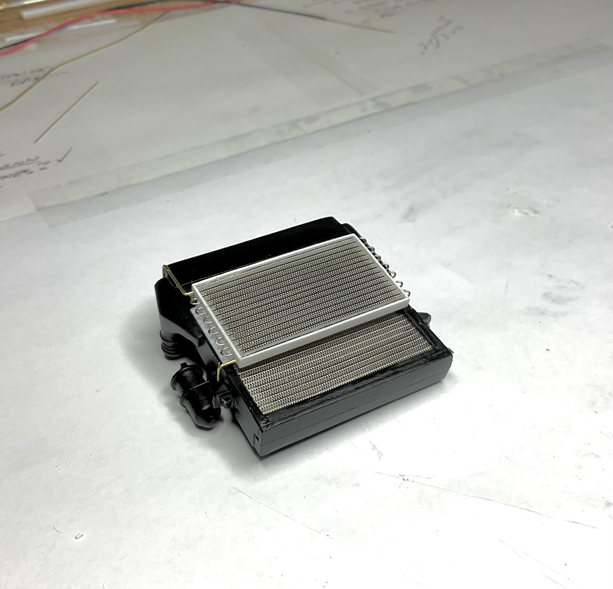
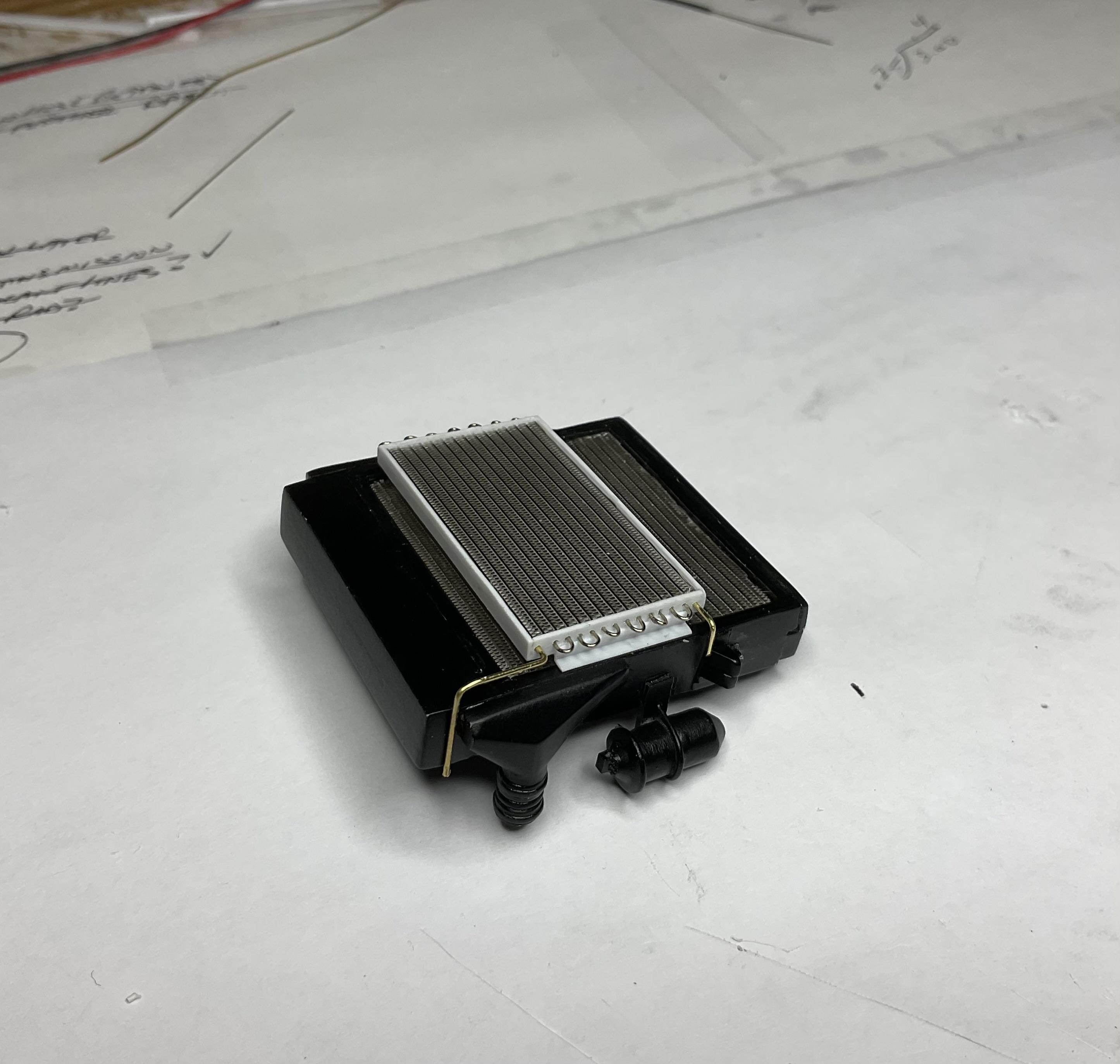
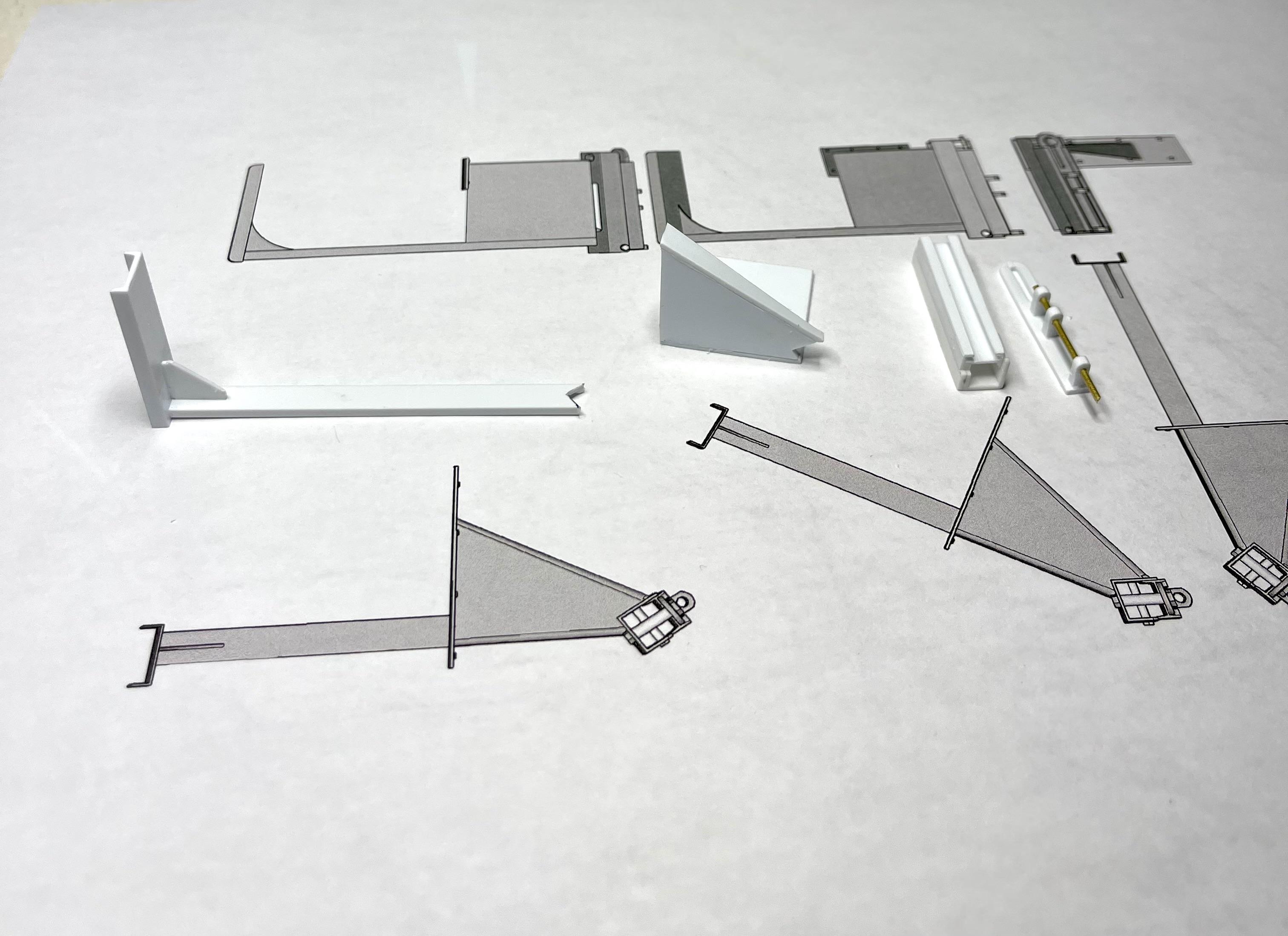
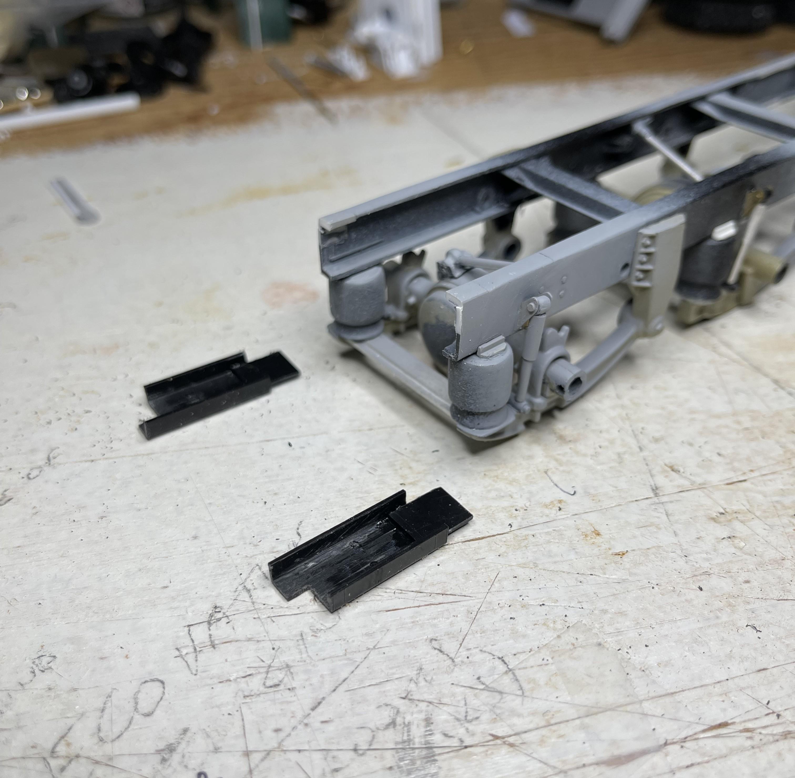
Western Star 4900 FA plow truck
BK9300 replied to BK9300's topic in WIP: Model Trucks: Big Rigs and Heavy Equipment
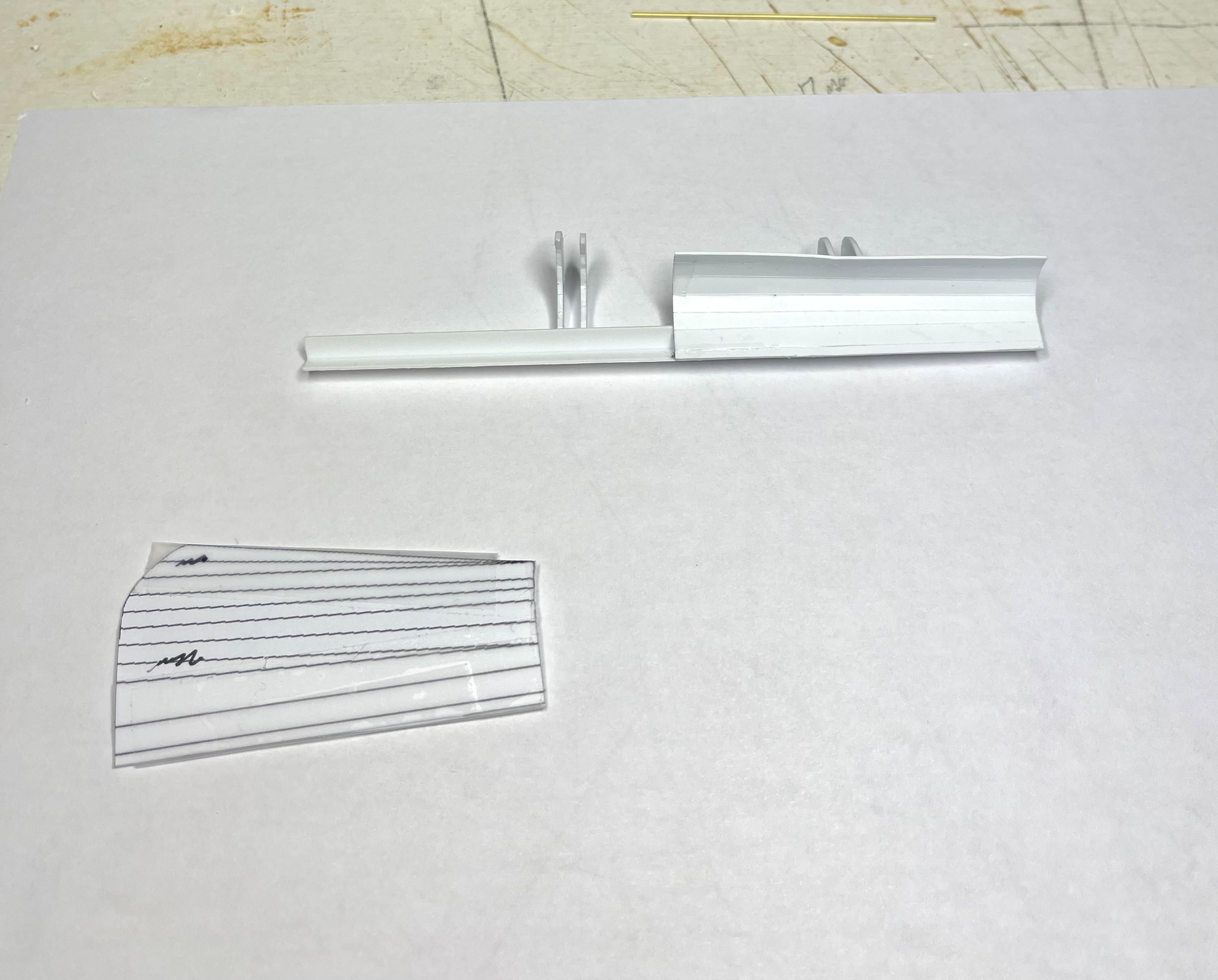
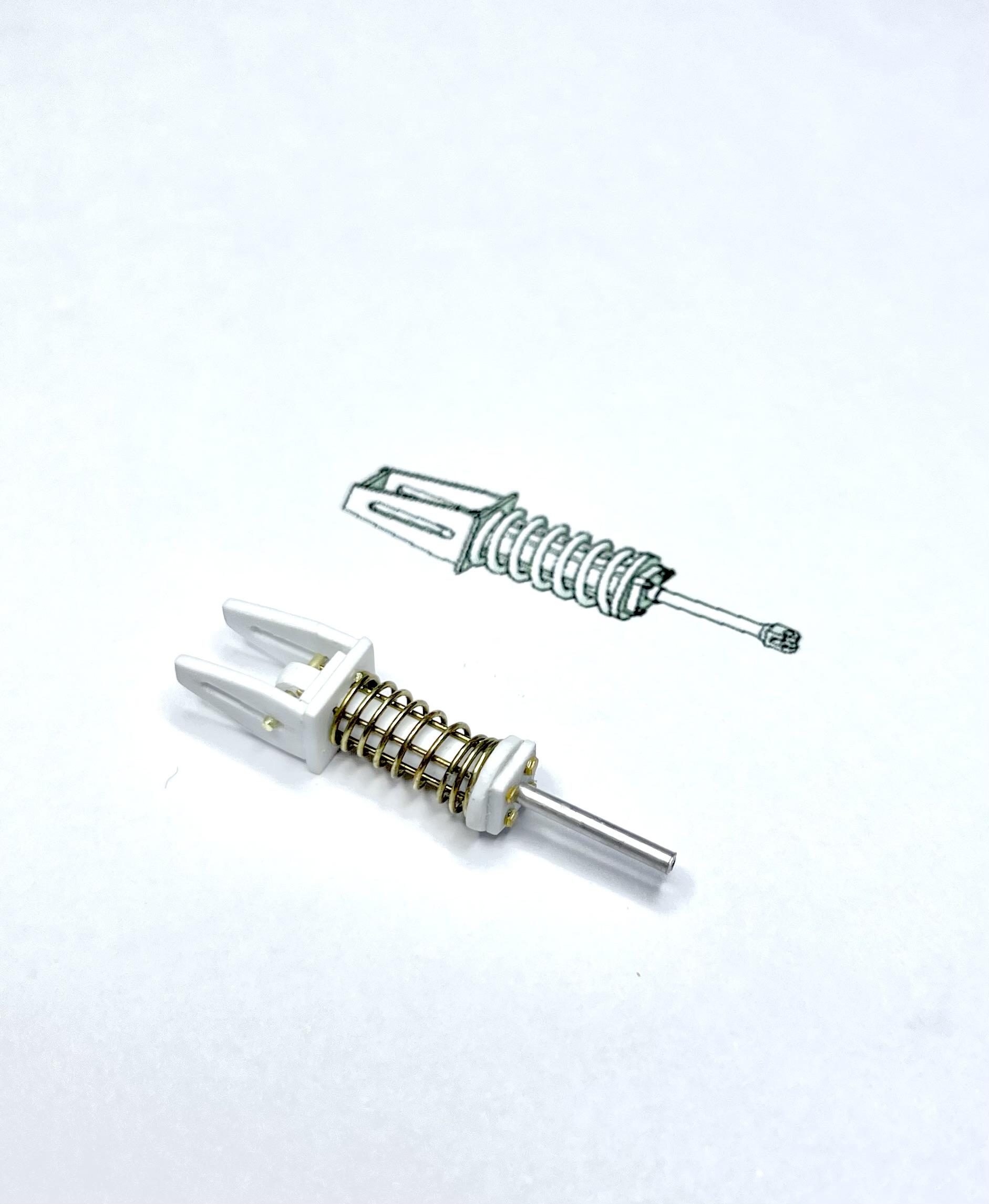
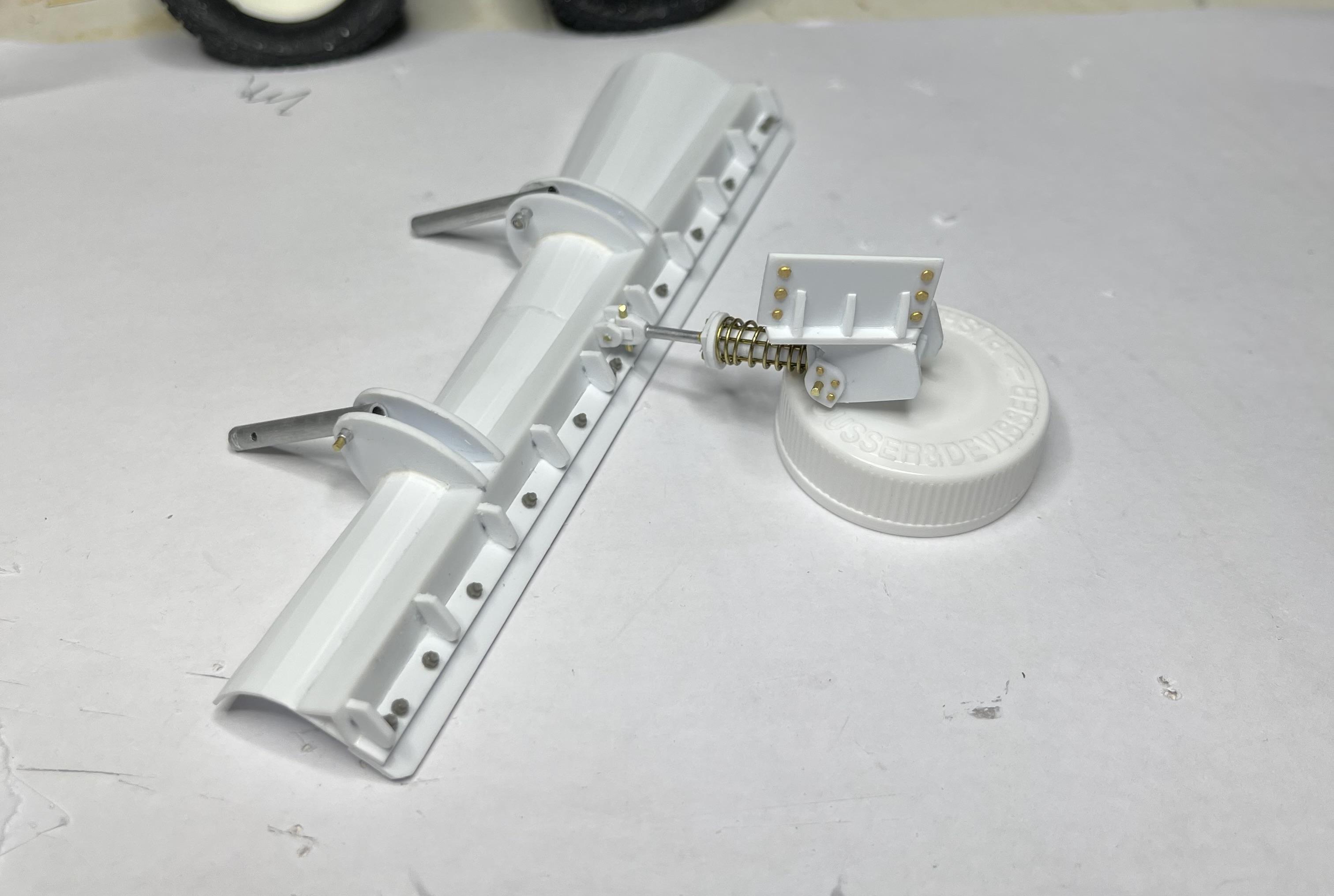
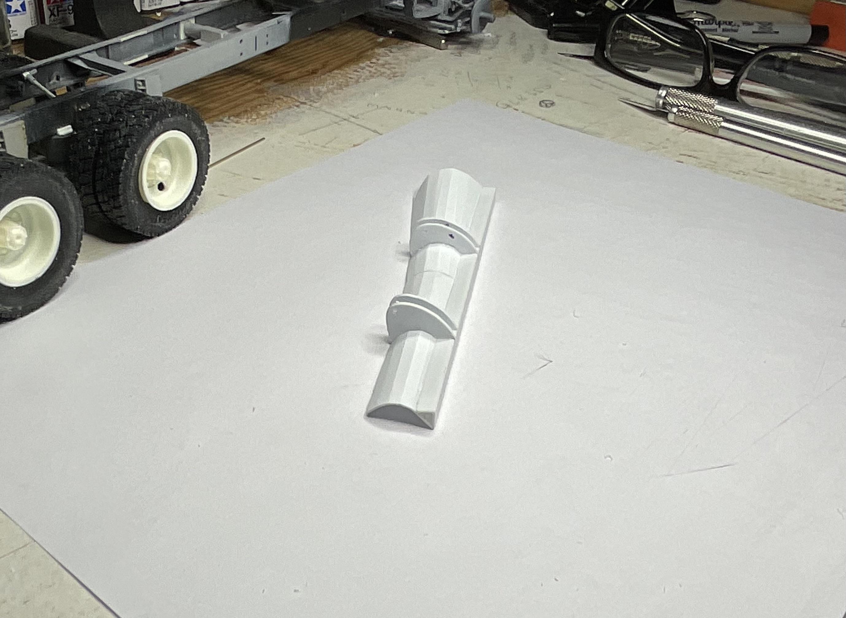
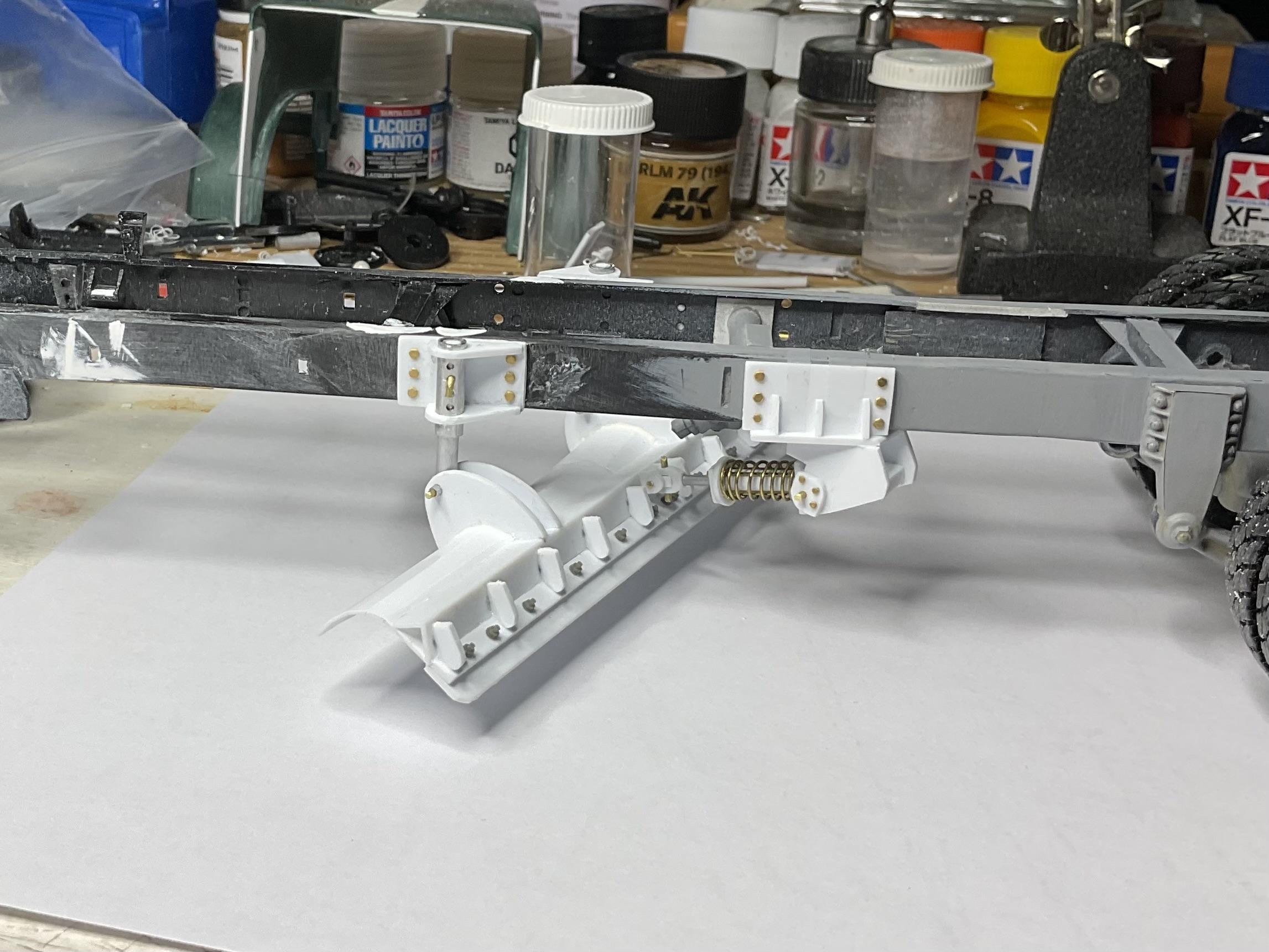
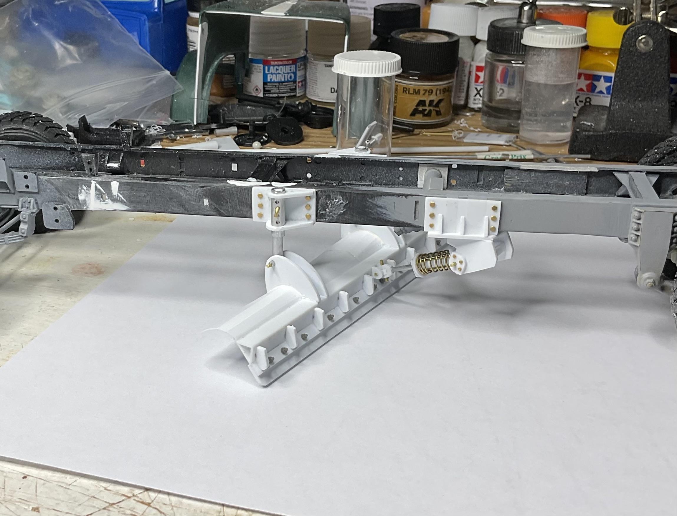
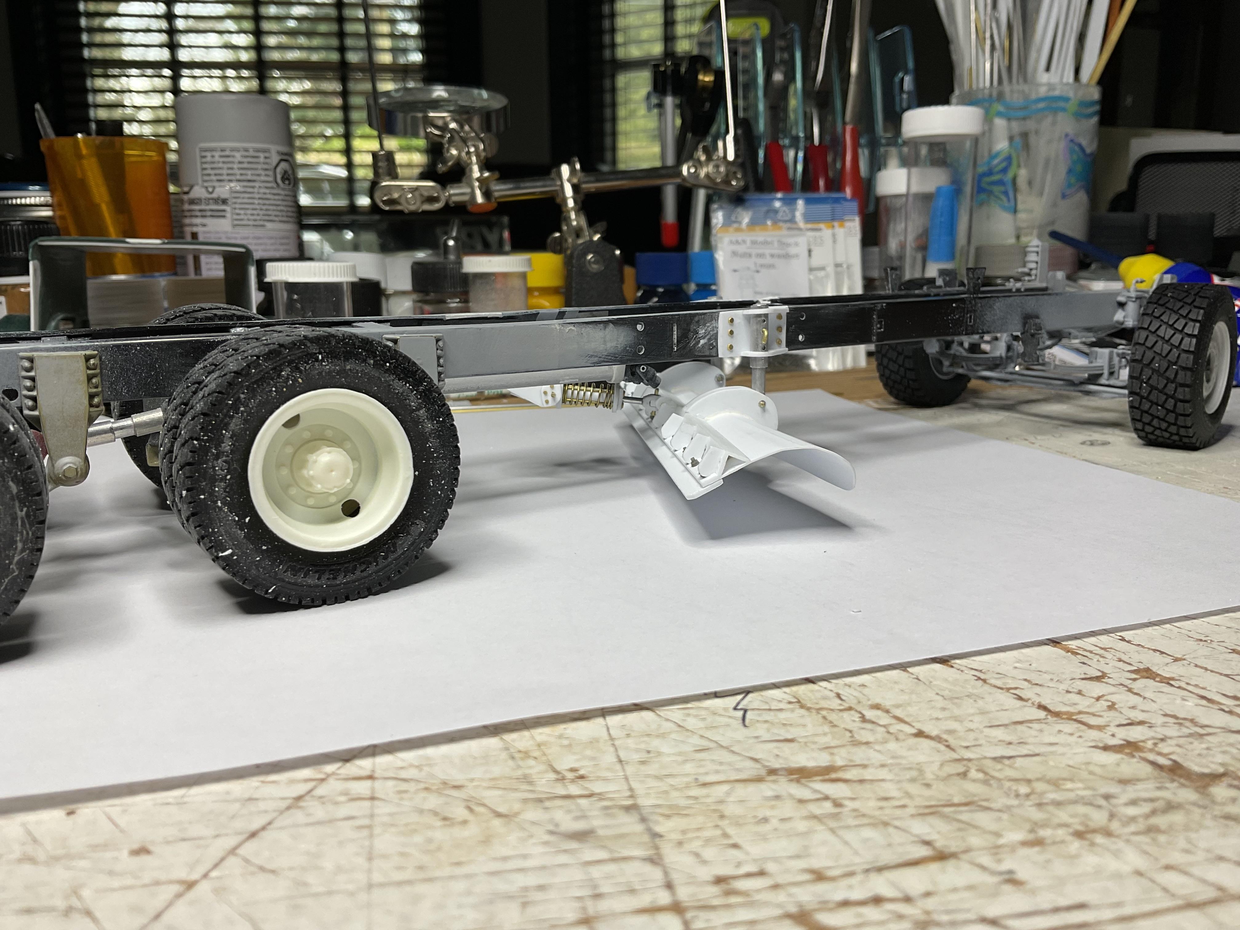
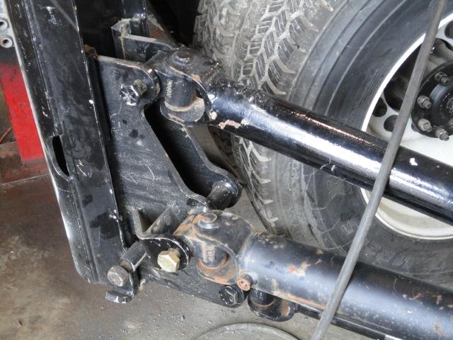
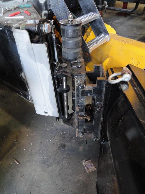
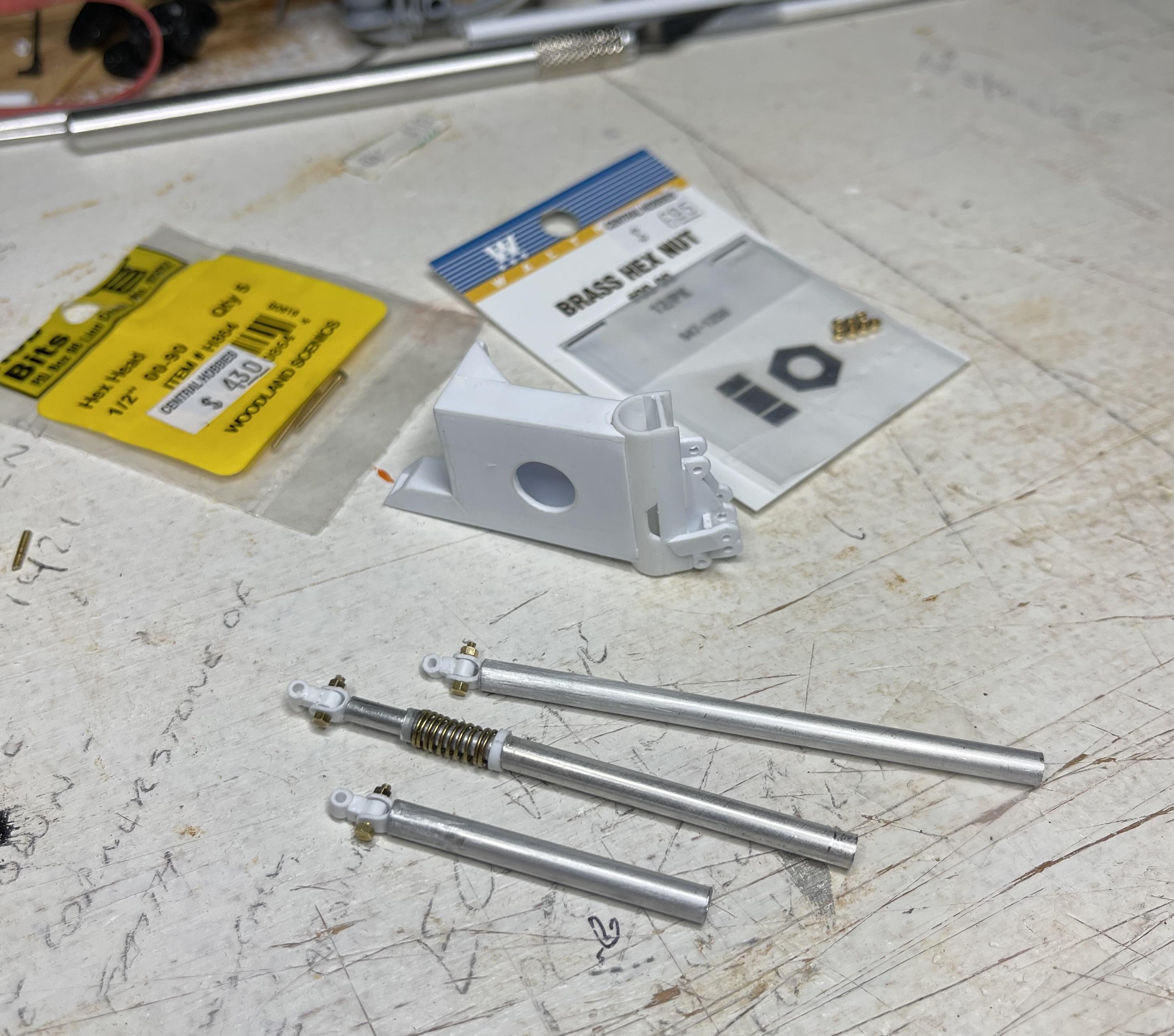
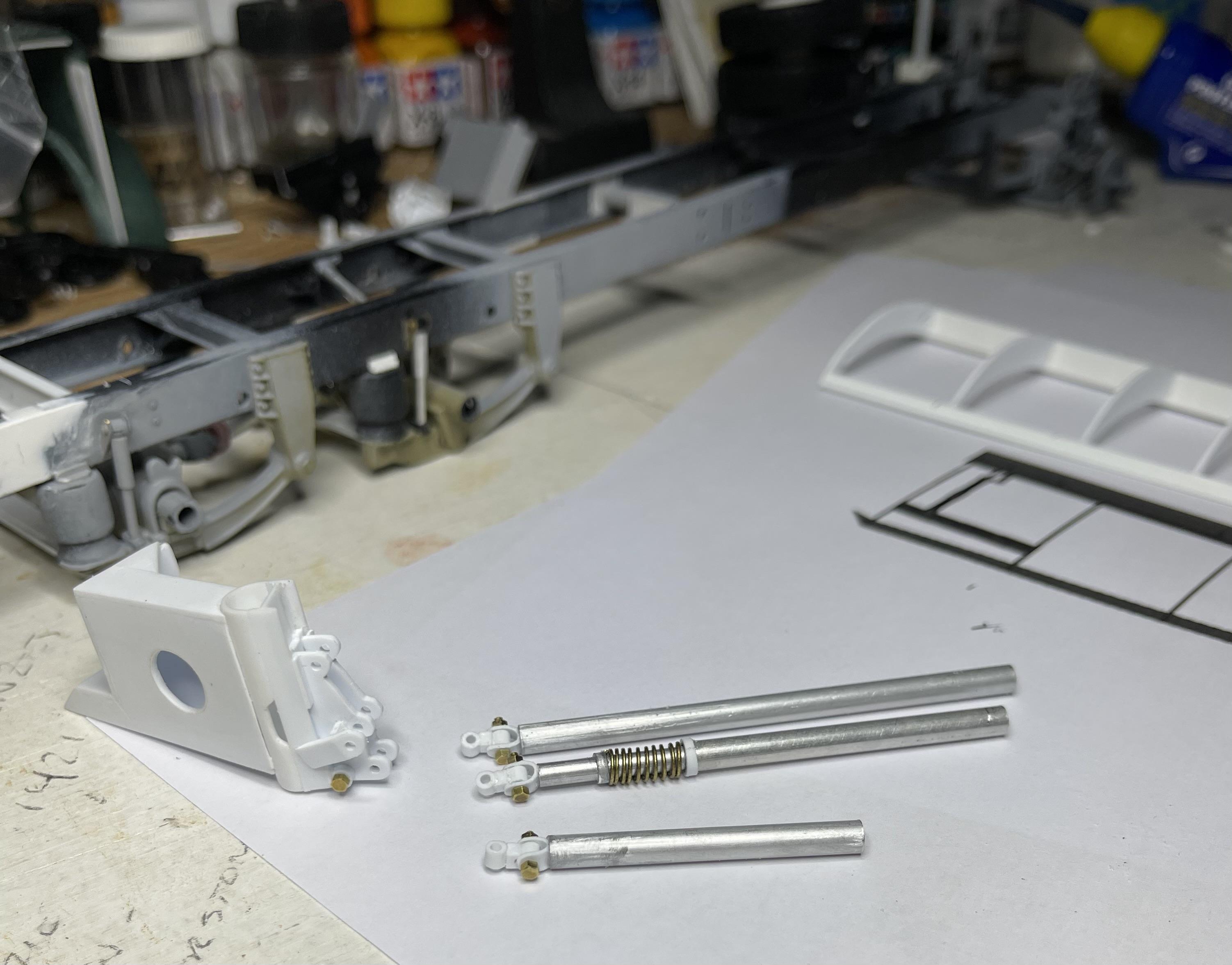
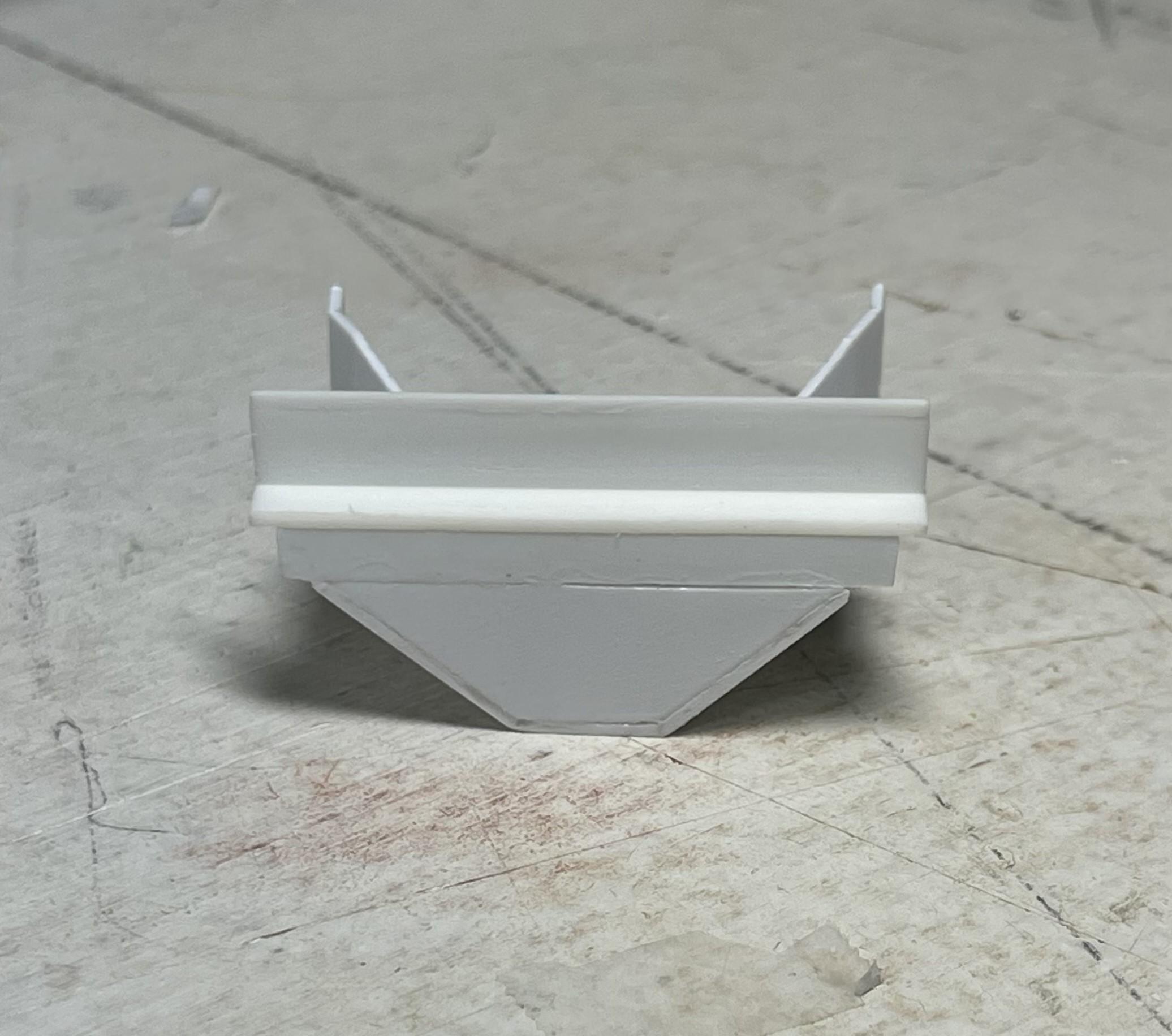
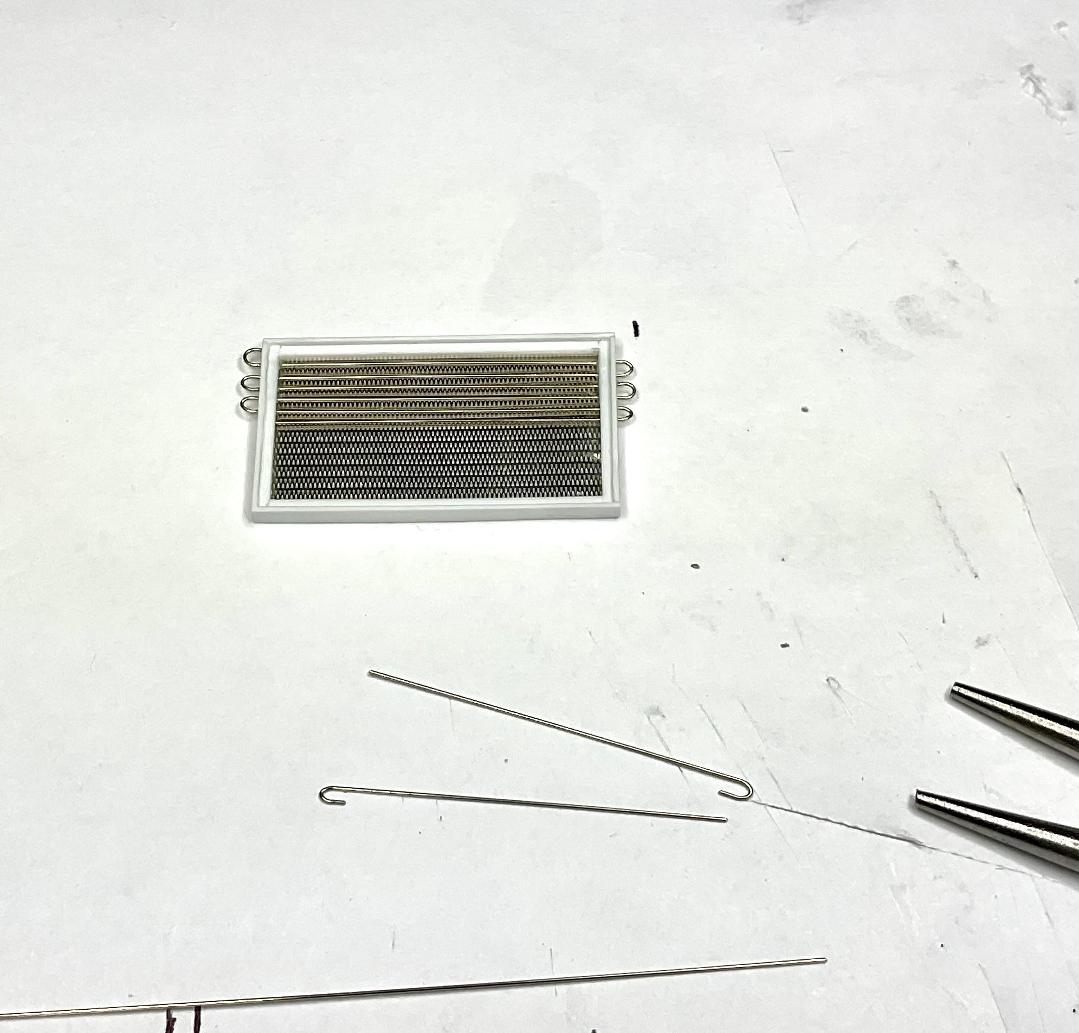
I worked on an air conditioning condenser, using the CTM radiator mesh front and back and 0.3 mm nickel wire to simulate tubes; want to build a transmission cooler to mount below the AC condenser – just haven’t figured out what to use for the thin vanes; built a drop center towing crossmember - some of our winter trucks were converted to truck and pup units for summer; started making the frame mounted supports for the rear (rear, RH side) wing plow, using the patterns I printed from my Sketchup model; made a measurement mistake and had to lengthen the rear of the frame because first attempt at the rear mount was rubbing tire – glad I made the change! drop center towing crossmember - took lots of pics of one of our trucks under construction and used the Western Star Body Builder notices as well work on the AC condenser hoping to plumb in the AC brass return line and outlet to receiver/dryer later in the build - transmission cooler to mount below yet as well patterns were trimmed and taped to 0.5 and 1.00 mm styrene sheets and cut out using razor saw - haven't made the leap to 3D printing, so lots of elbow grease sawing out parts! this front mount lowers and raises the front tip of the wing plow - another piece for it to come yet sample view from Sketchup model - this final part swivels on front mount for wing plow and the front of the plow rotates on the bolt shown as the rear of the plow is lifted lots (lots!) of pieces cut out during this build mock up of the towing crossmember and wing plow frame mounts in place - screw up with rear mount - need to lengthen frame to clear tire - the lever assembly with the brass rod going up through the “grooved cylinder” (represents a rubber component) is an anti-kickback mechanism to dampen any impact of the lower front plow blade and uneven road surface rear mount is correctly space now - no blowouts! (these are not the final wheels for this build). mount doesn't look vertical but will when finally set in place need to leave it at that for now - more to come!
-
Western Star 4900 FA plow truck
BK9300 replied to BK9300's topic in WIP: Model Trucks: Big Rigs and Heavy Equipment
Thanks, Gary - first truck build in over 30 years - lots of new skill needed to be learned on the fly! -
M-20 Prime Mover is Finished
BK9300 replied to Chariots of Fire's topic in Model Trucks: Big Rigs and Heavy Equipment
I am in awe of your brass work - its a skill I'd like to learn - amazing detail! -
1953 Mercury M100
BK9300 replied to Chuck Most's topic in Model Trucks: Pickups, Vans, SUVs, Light Commercial
I like the way the late afternoon sun makes the truck seem to glow - very clean build. Just got a notice from Model Roundup that Moebius Models is releasing a 1968 M 100 pickup in early August. -
Hello everyone, from North Vancouver
BK9300 replied to BK9300's topic in Welcome! Introduce Yourself
Thanks Guys, still figuring my way around the forum (and waiting on the mandatory moderation period) - I'll get back quicker in the future! -
Donato, I don't know much about modifieds, but your quality build speaks for itself