François
-
Posts
489 -
Joined
-
Last visited
Content Type
Profiles
Forums
Events
Gallery
Everything posted by François
-
body prototype number 3 is fully assembled using an assembly jig. Next up are the panels. I found another material for the skin that is 4 way stretch and shinier. But is it better, not sure. I think what would be best in latex but I'm having a hard time finding some.

-
Fusion is not really the successor but a more affordable 3d cad system that will cater more to the educational/ hobbist crowd like autocar did in tge late 80's and 90's. Inventor is, for now at least, a more powerful mecanical design tool.
-
Thanks Bugatti, I'm not using fusion 360, l work with Inventor which is a mecanical design software. So making 2d line drawings from the 3d cad is quite easy, every part I would design had to be transfered to a 2d line drawing so it could be machined.
-
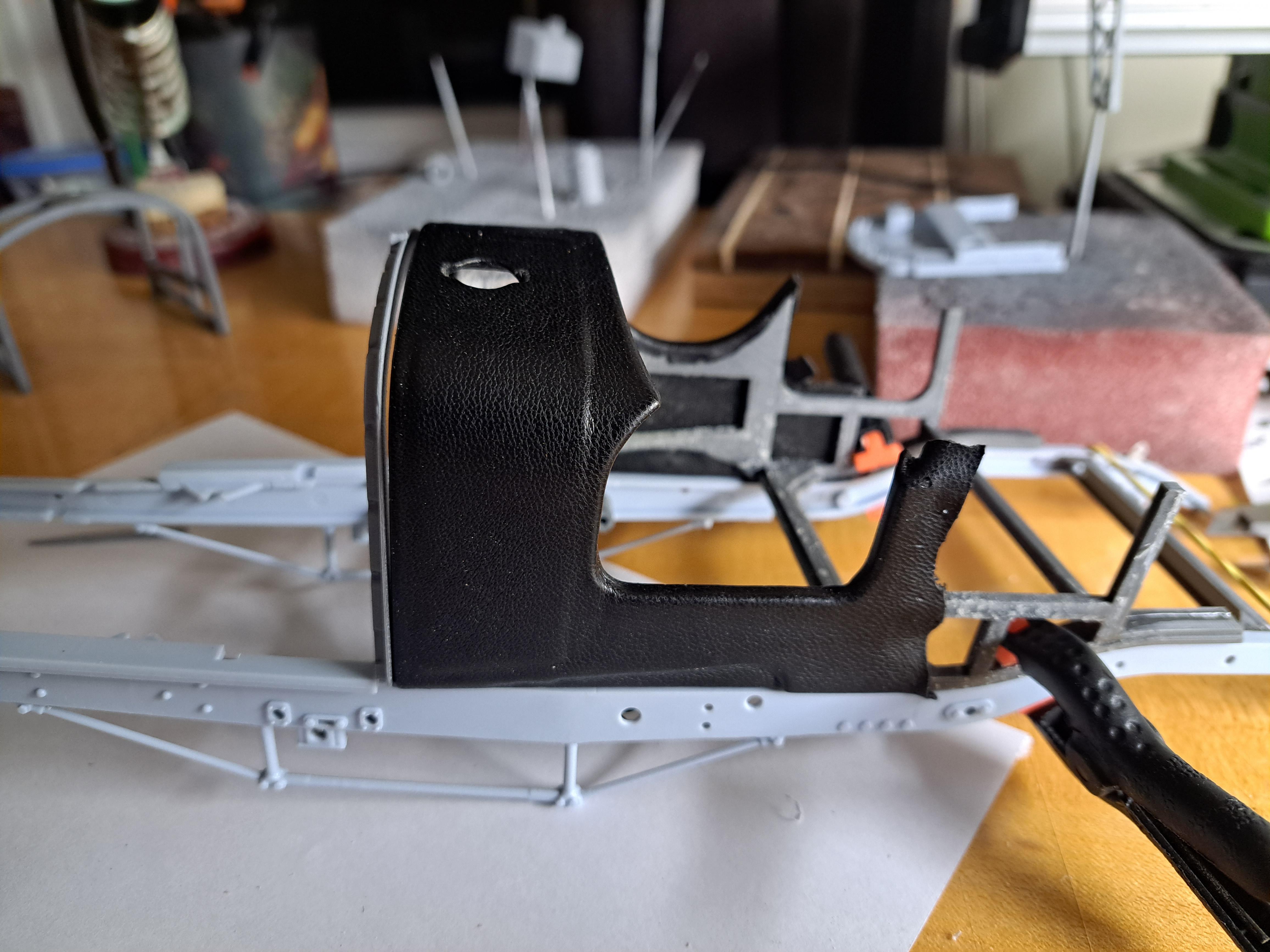
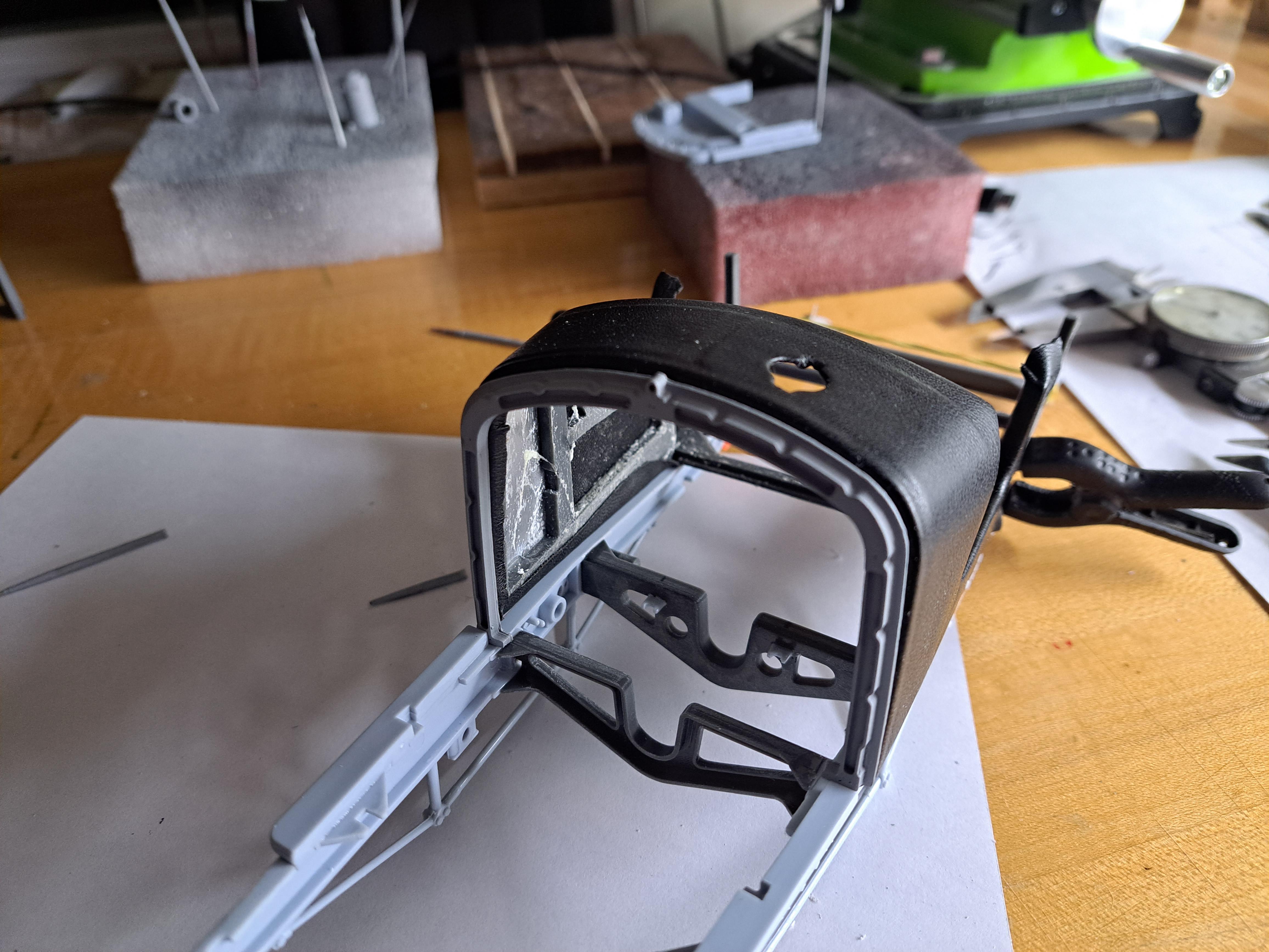
Still working on the second body prototype. Added the aluminium sheets to the front portion and tried my hand at covering it with the faux leather I found. Not to bad for a first try. I still have to work on the flatness of the assembly so that the seams aren't as visible. Not sure about my fabric choice. The ref car look a bit more shiny.
-
Second prototype of the body. I'm getting closer with every try. I'm trying different slicer applications to see which will give the better result.
-
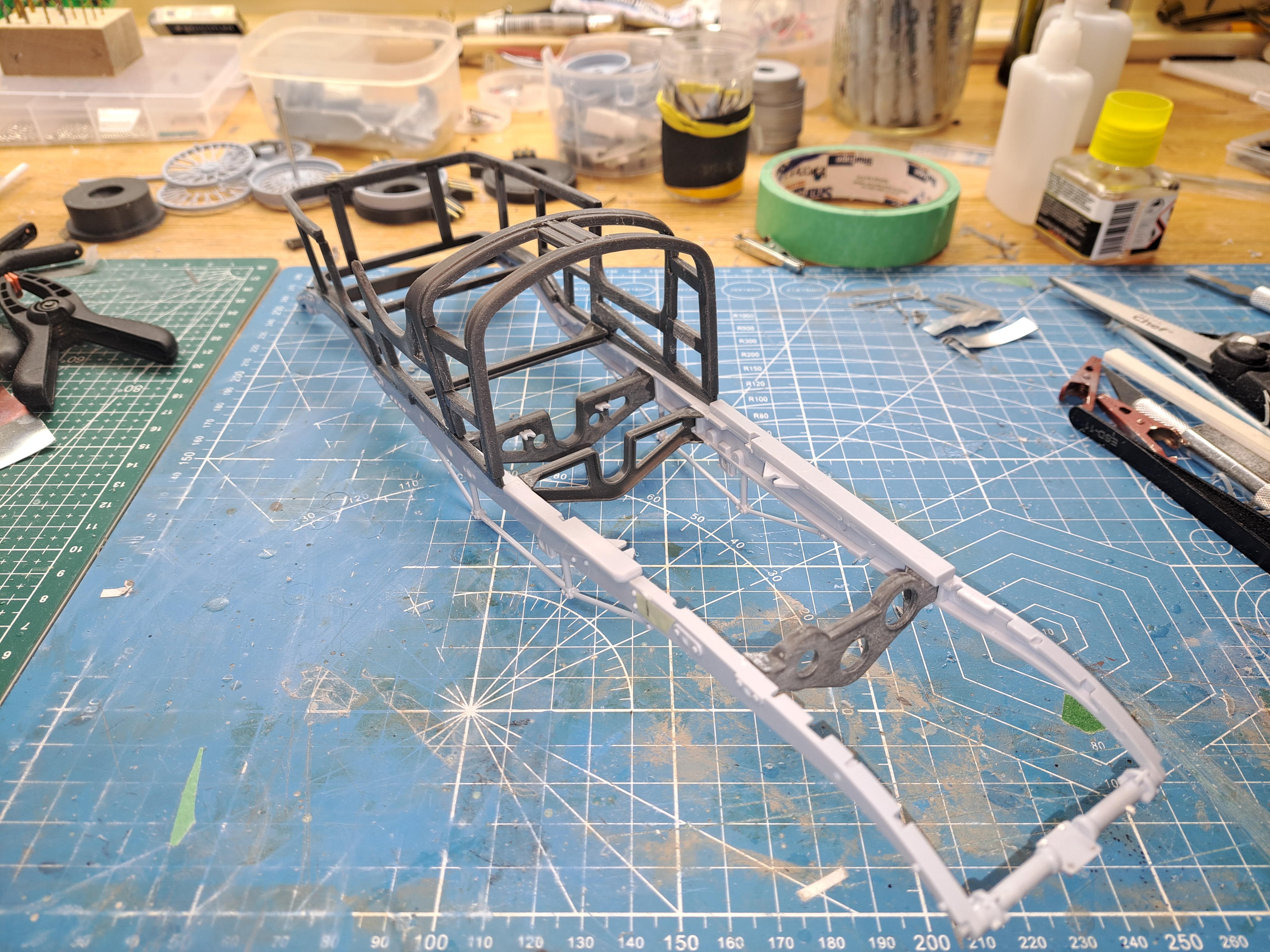
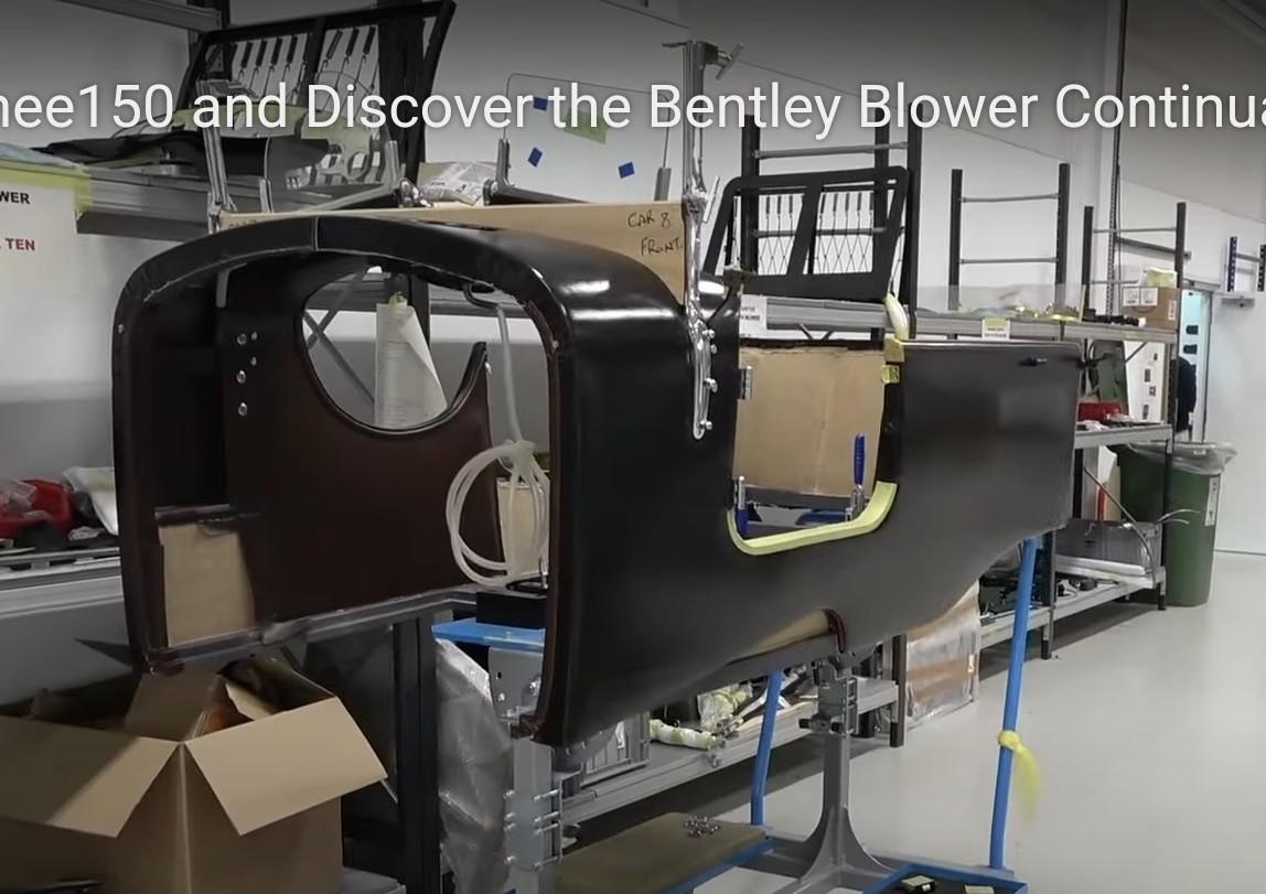
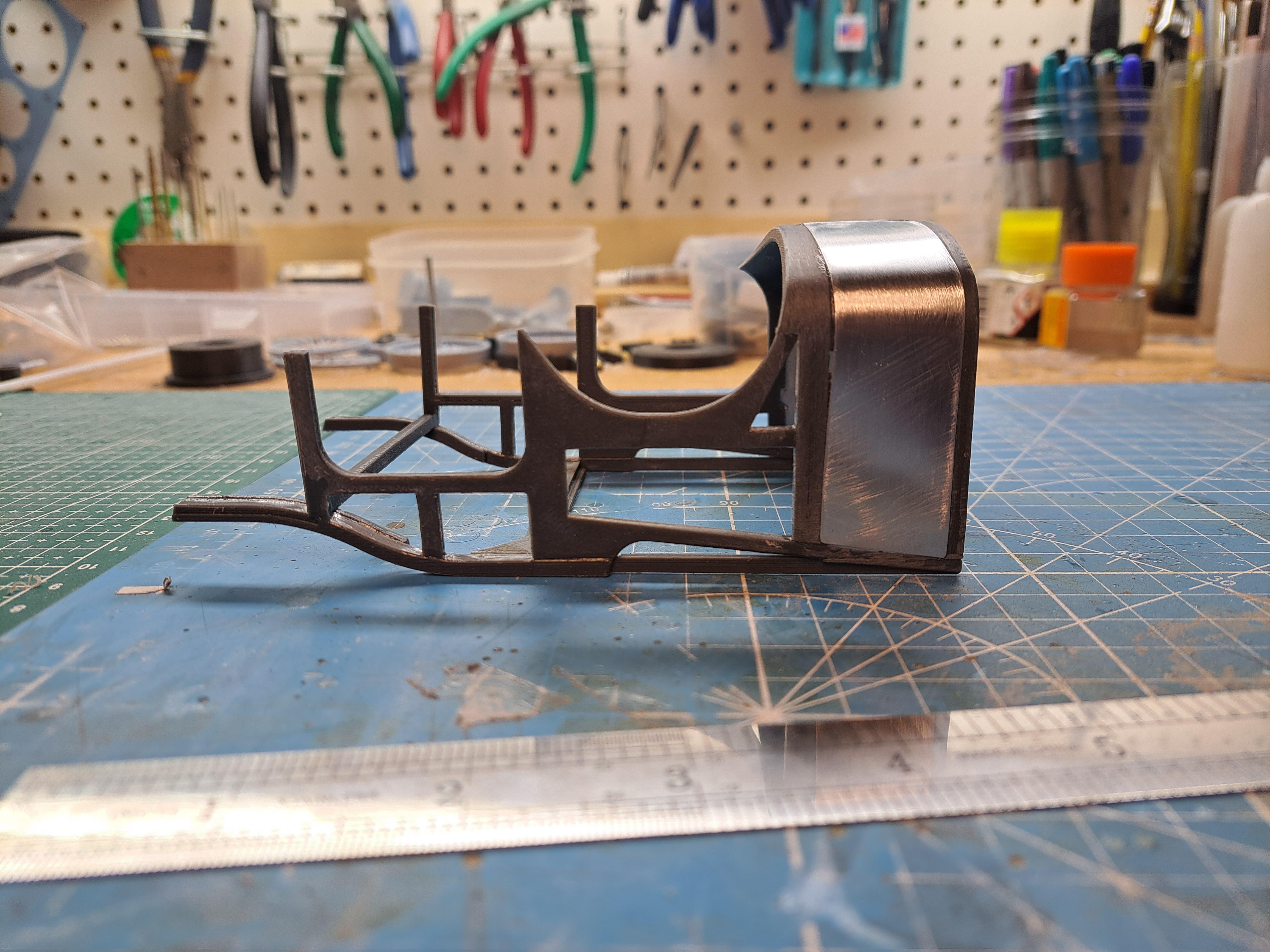
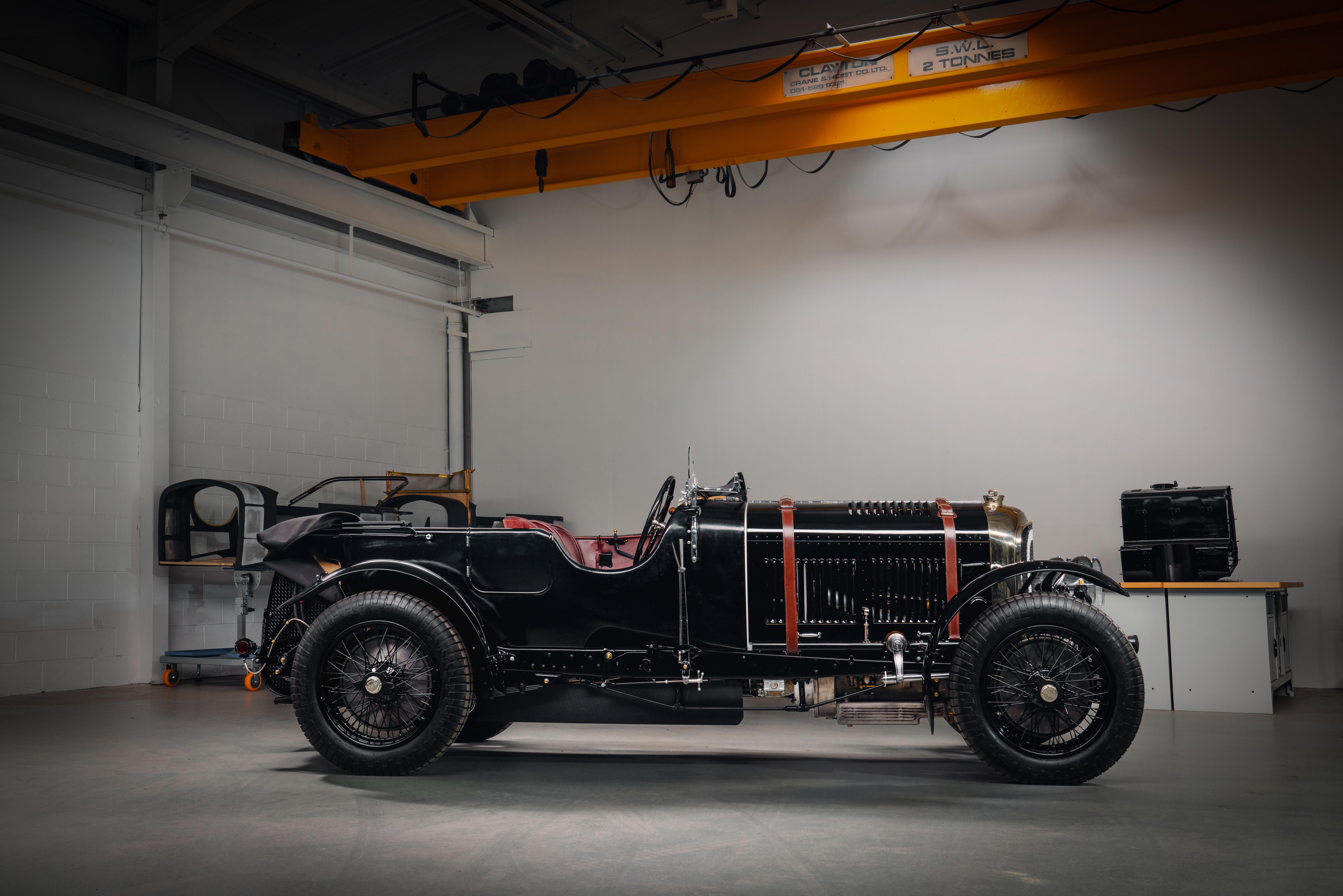
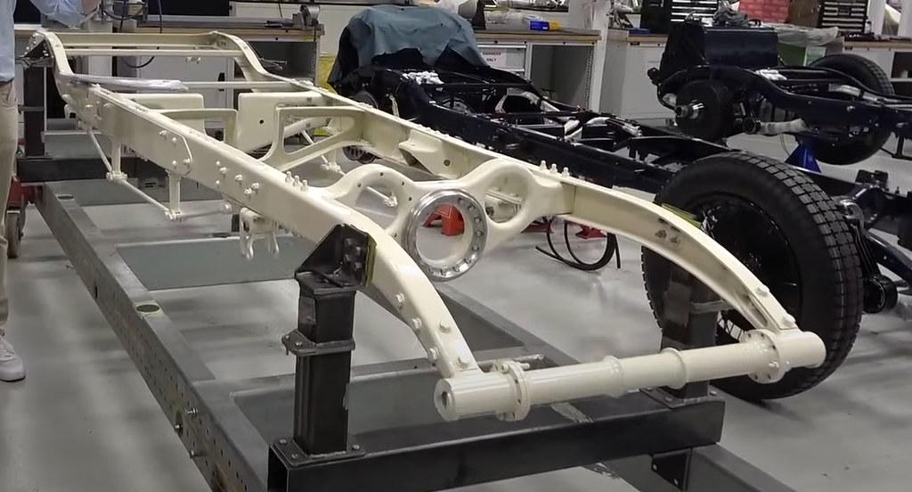
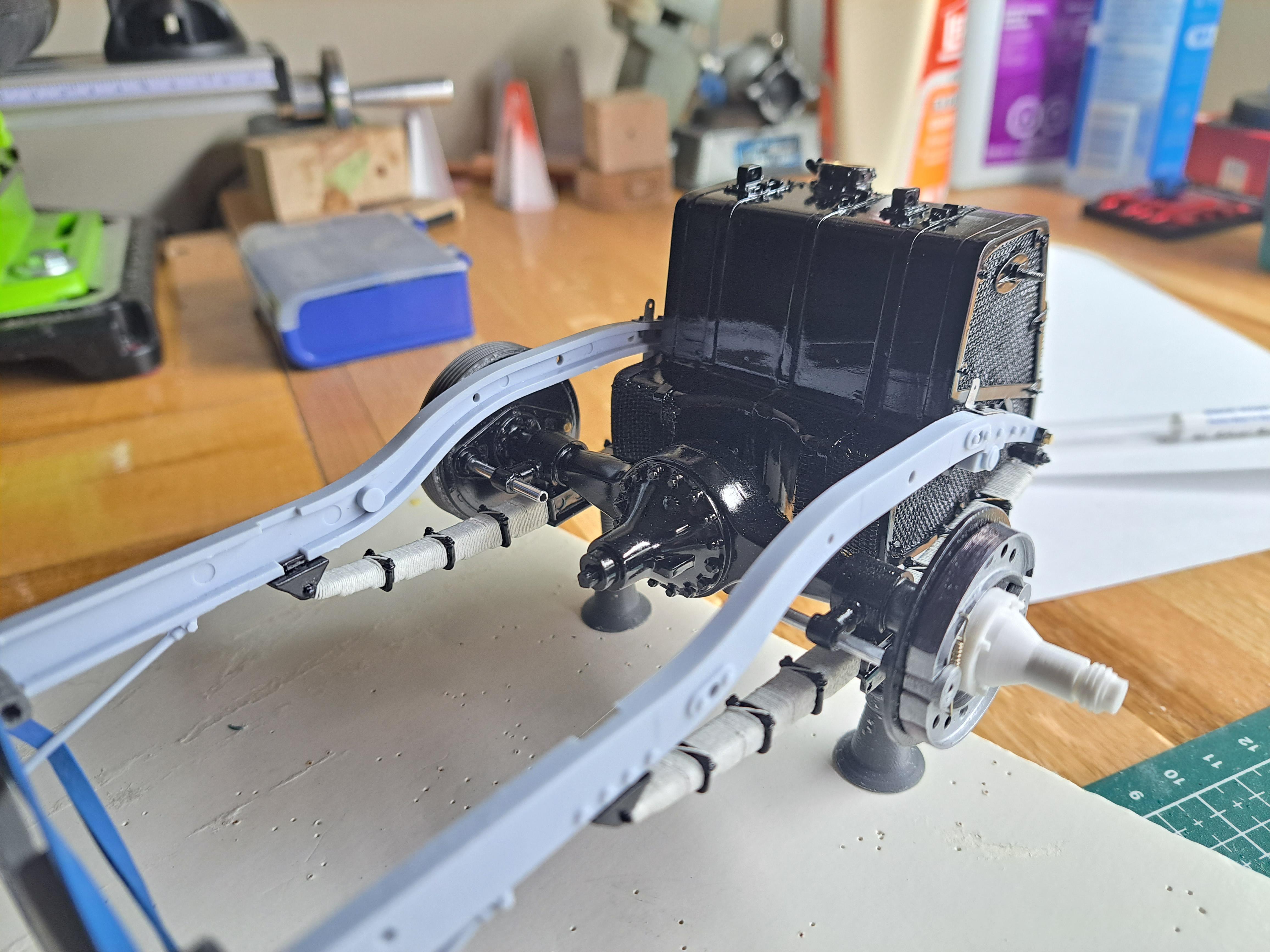
2 big steps were achived today. I finally assembled the ladder frame with a mix on kit parts and newly printed parts. Everything went together well. next, I test printed the front portion of the body. I wanted to see if the parts were printable and how they would fit together. Again, I'm very happy with the result. Even if preliminary, it is promissing Althougt I'm not sure l'll ever make it in wood. Here the newly completed 3d body on the frame and as a reminder, the real thing Next, I'll do some test fitting of the aluminium sheets on the body.
-
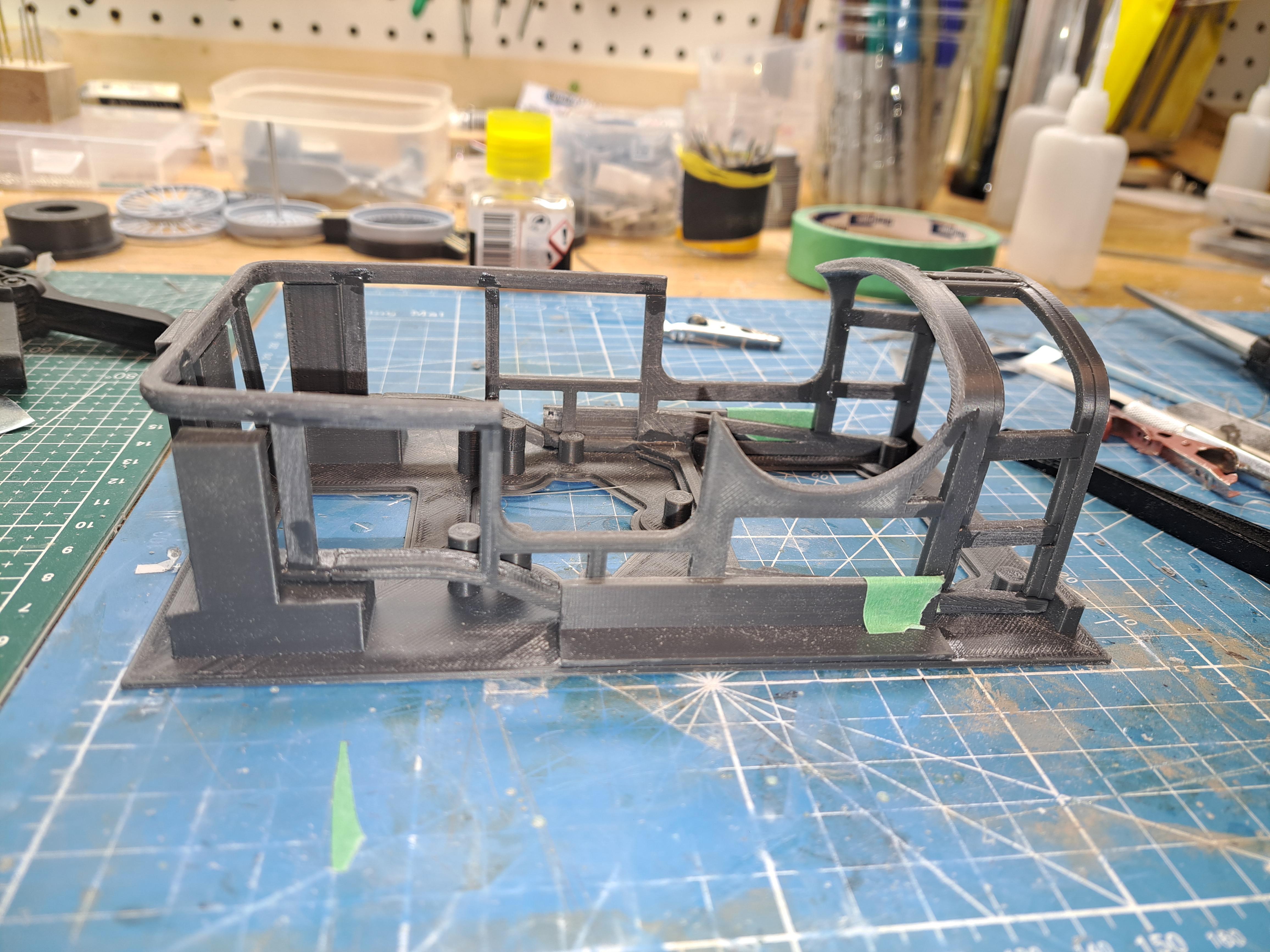
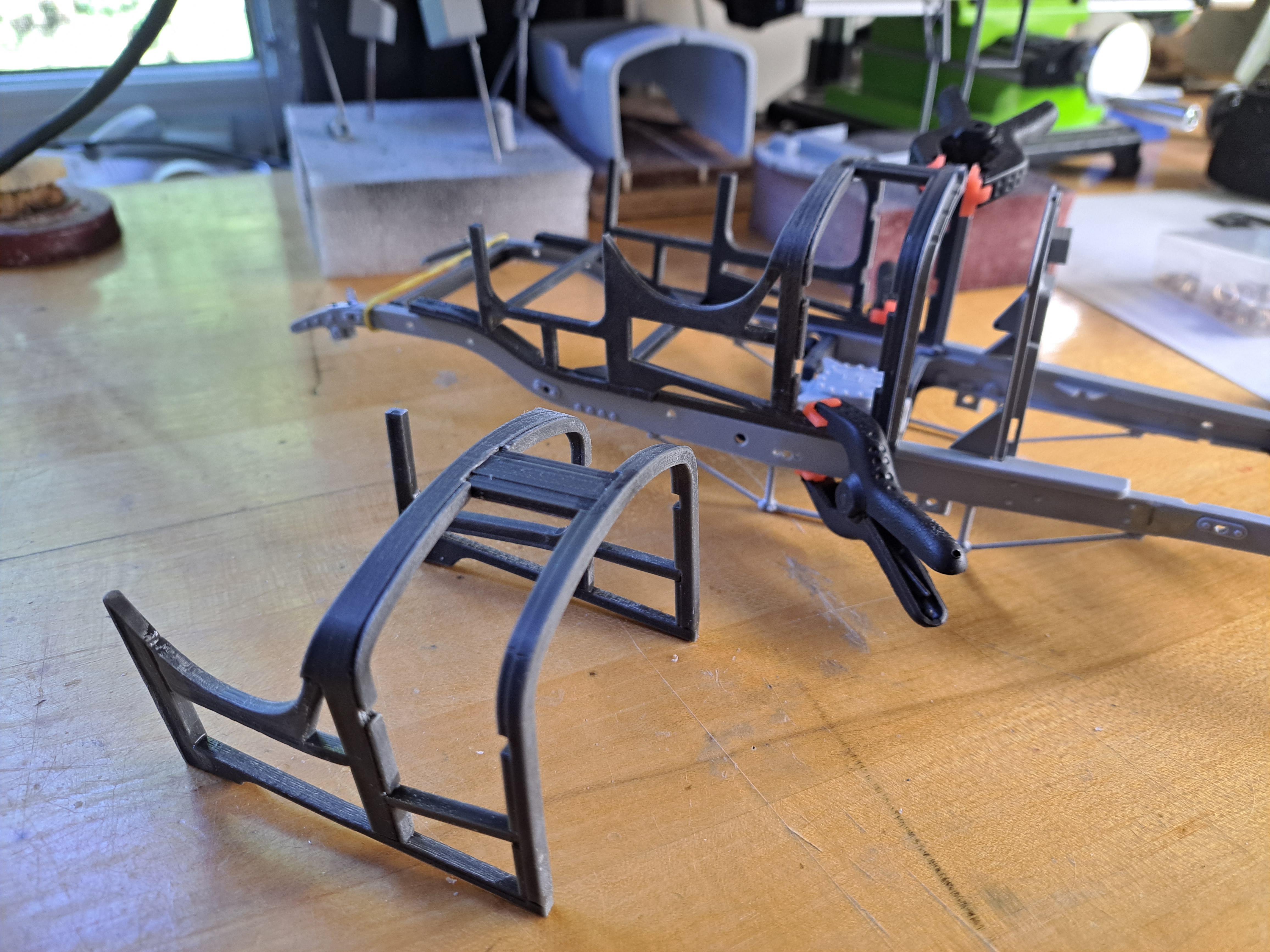
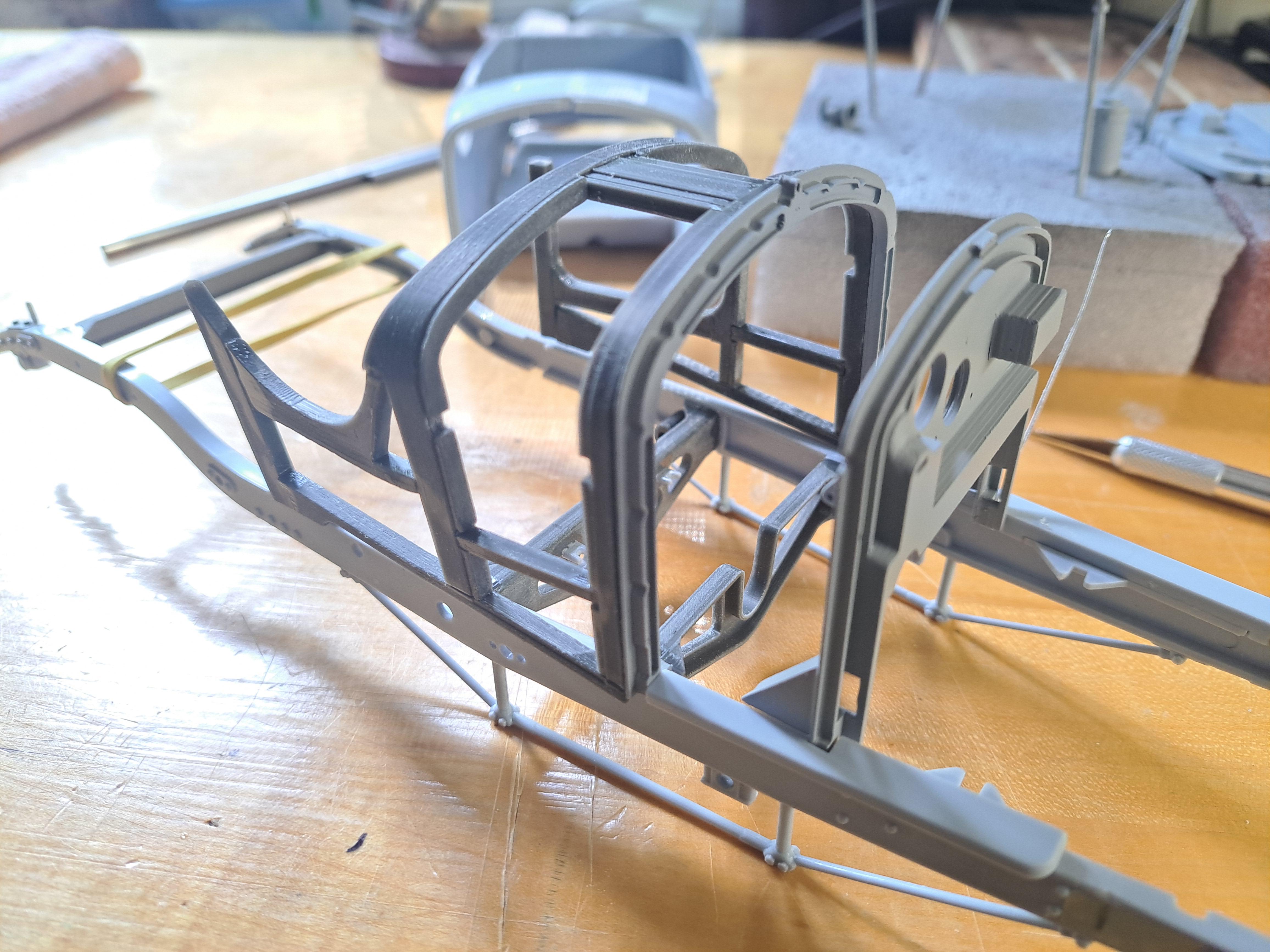
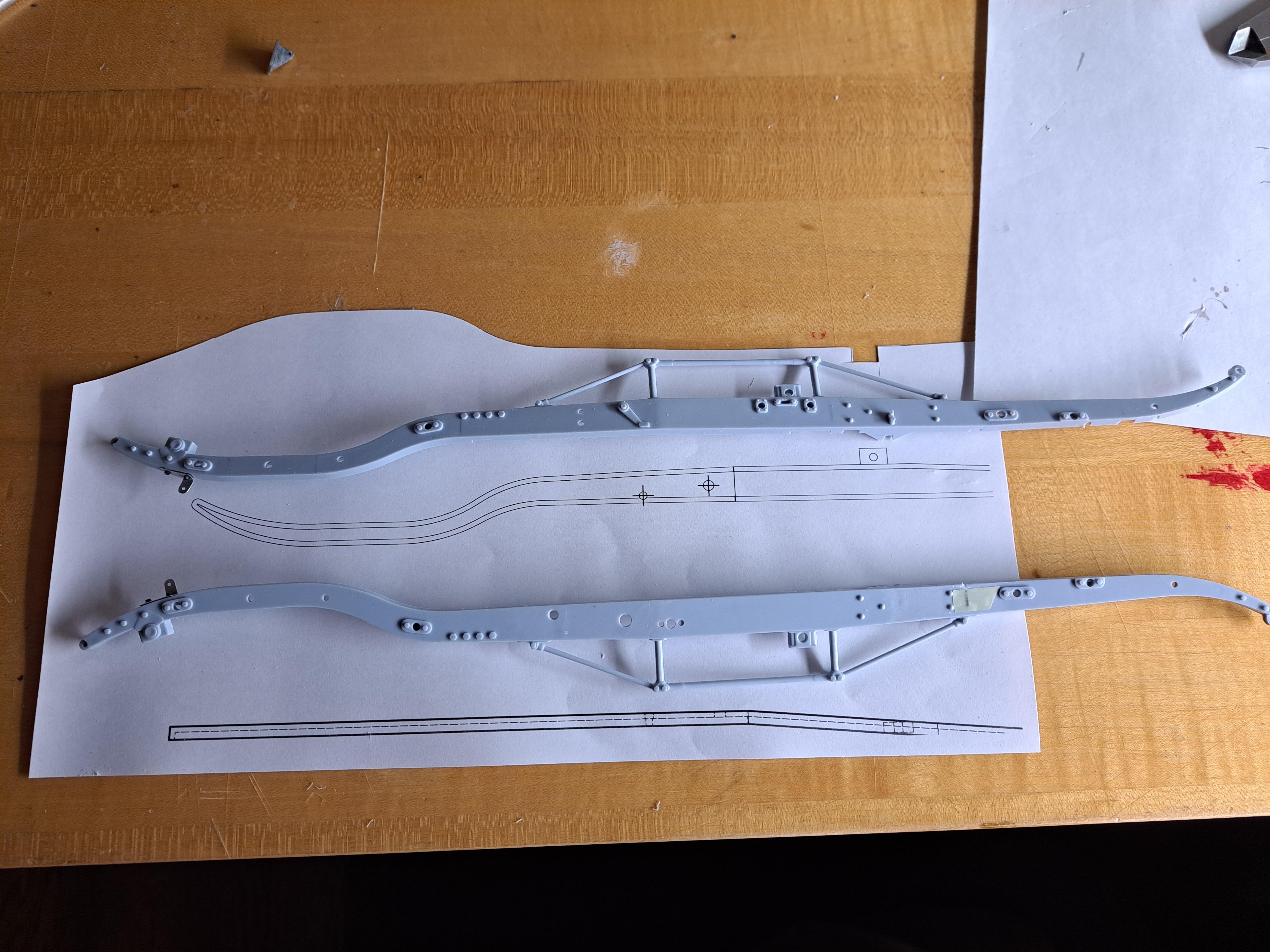
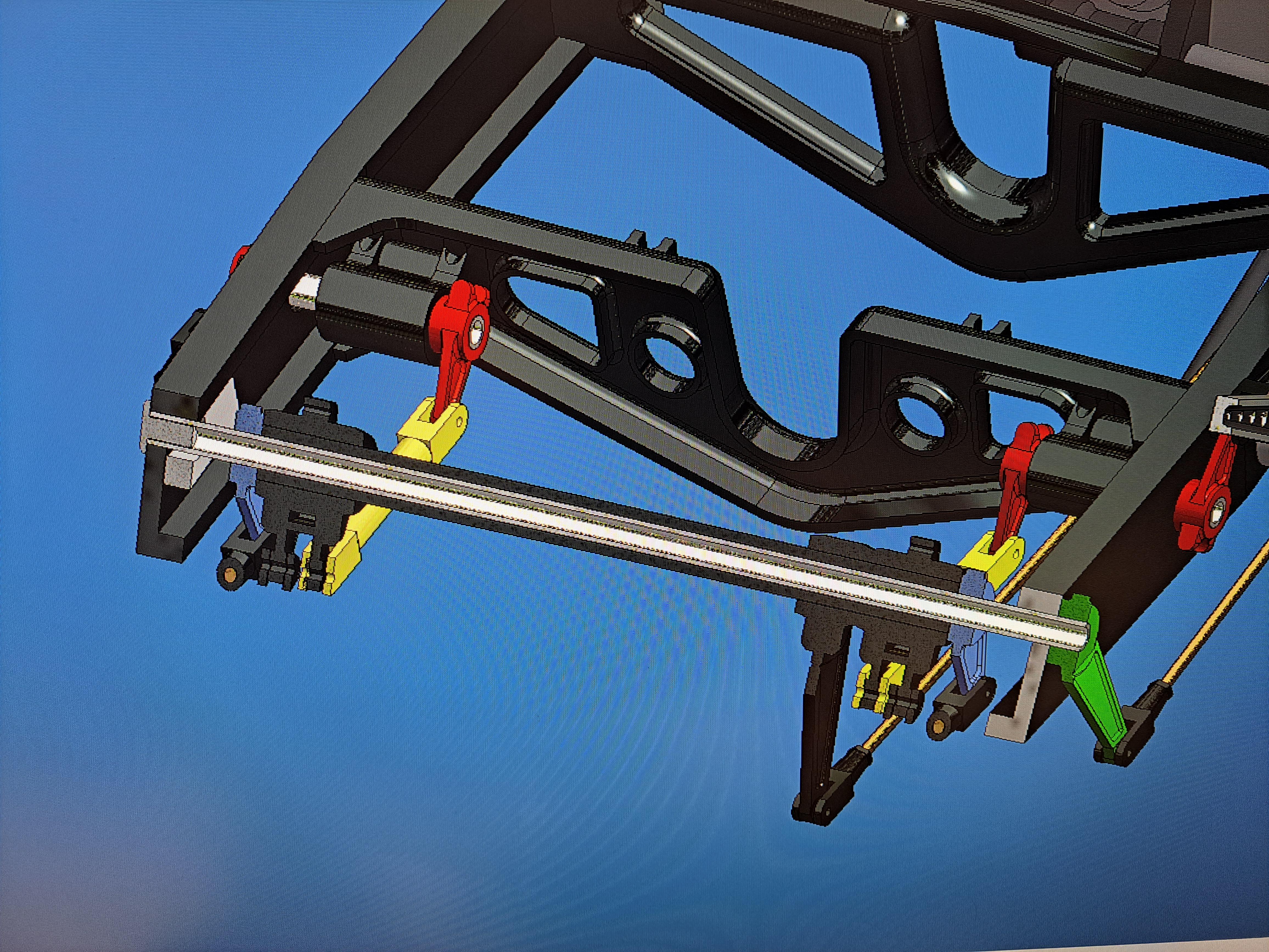
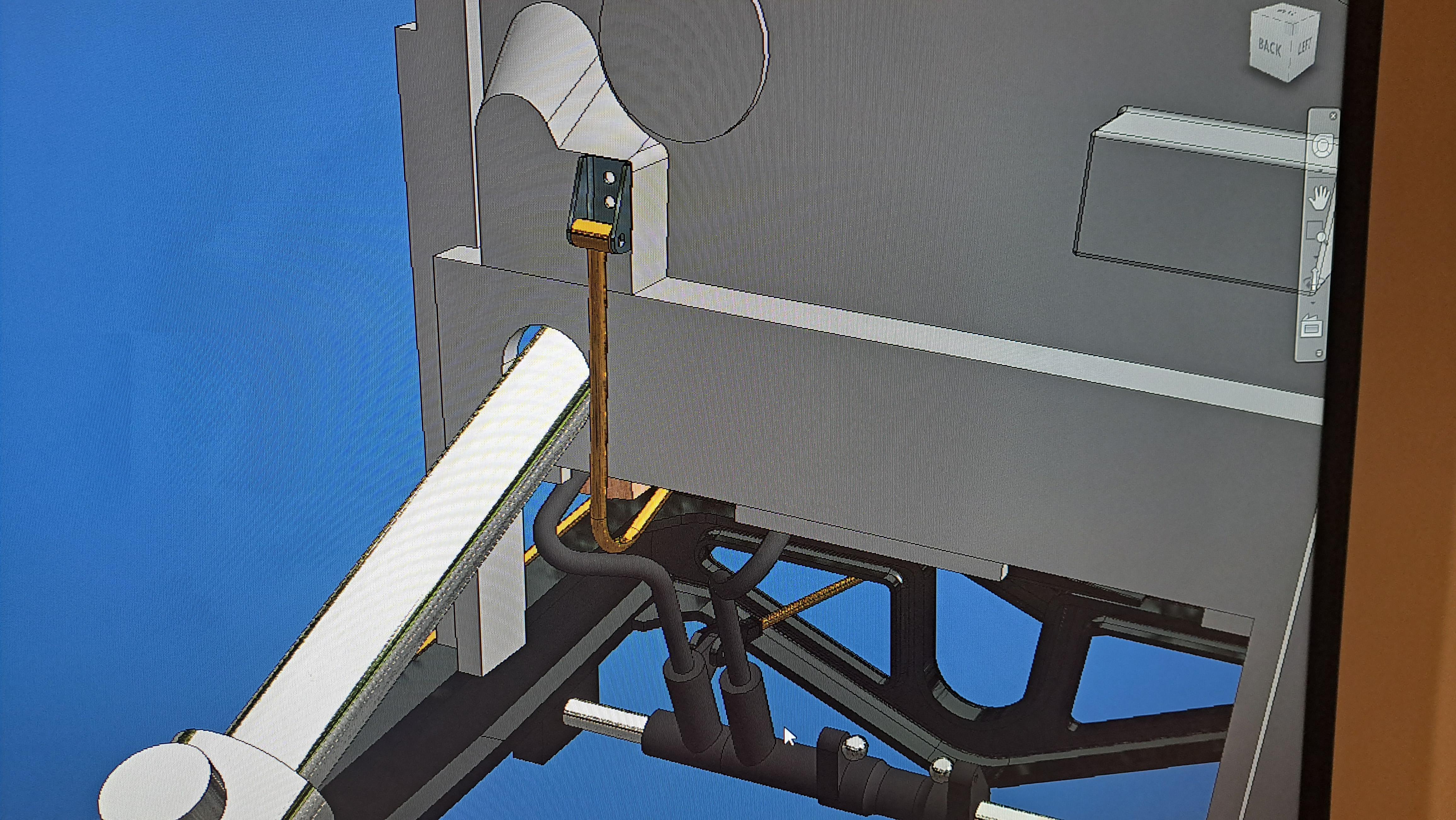
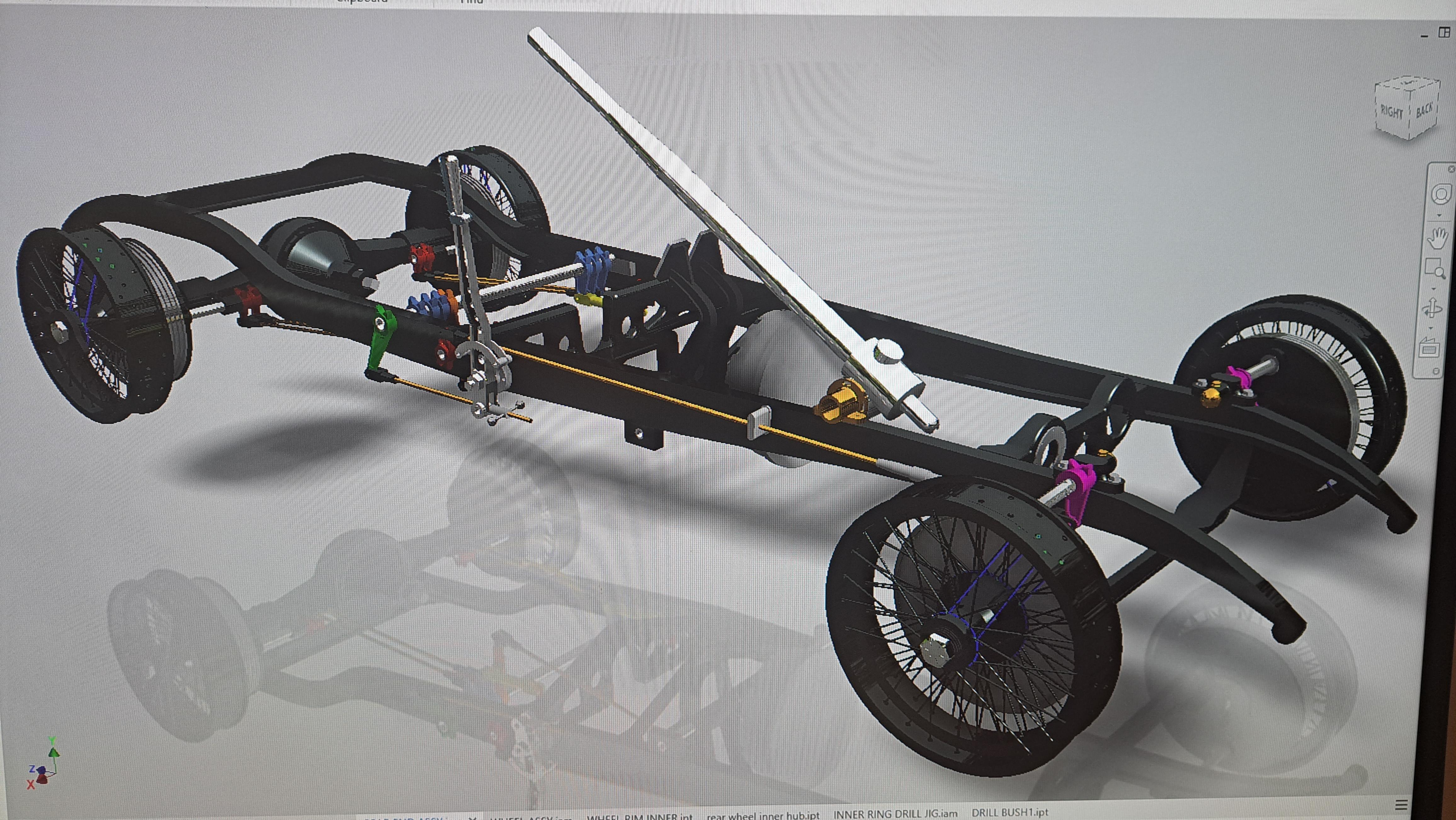
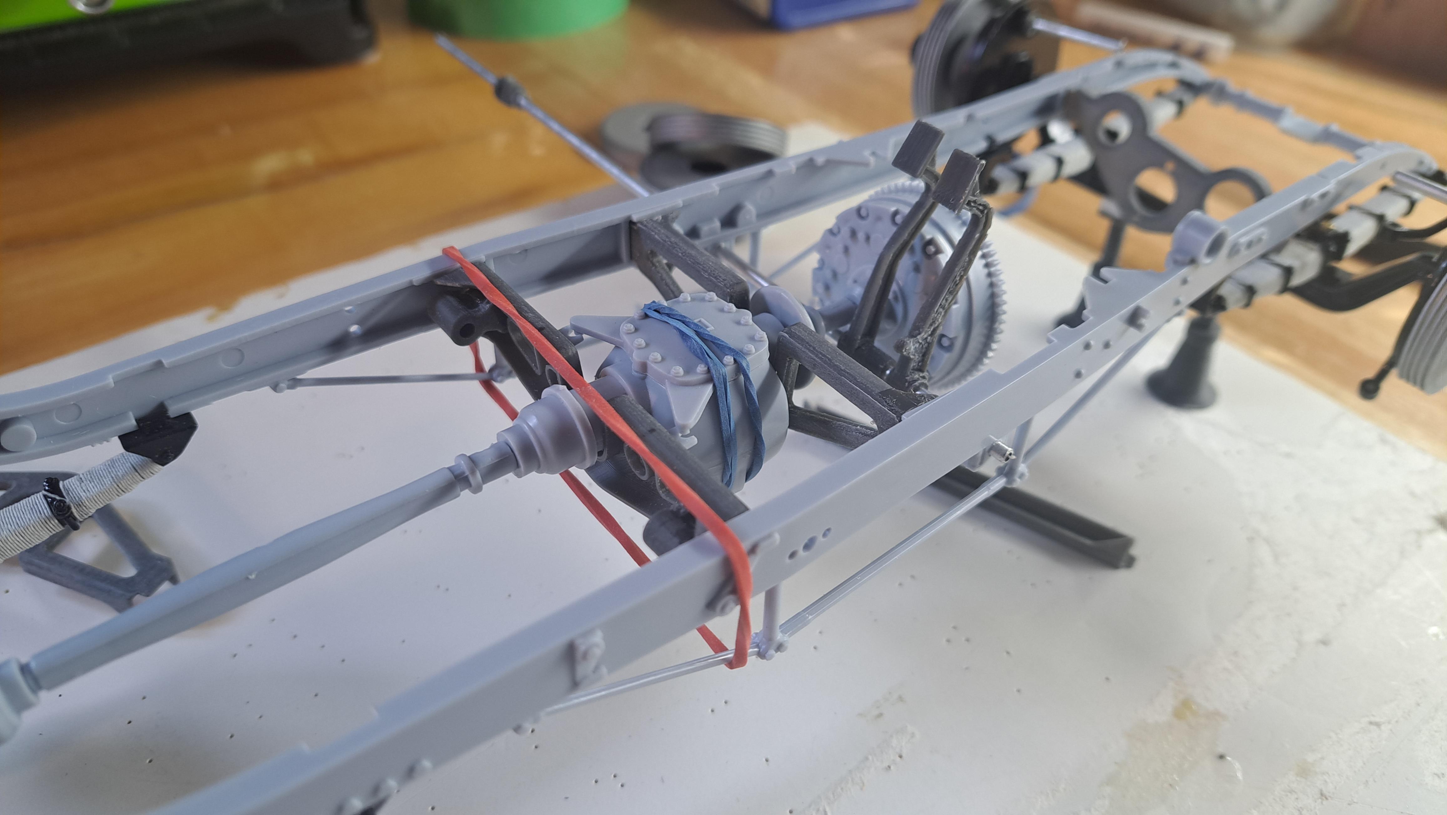
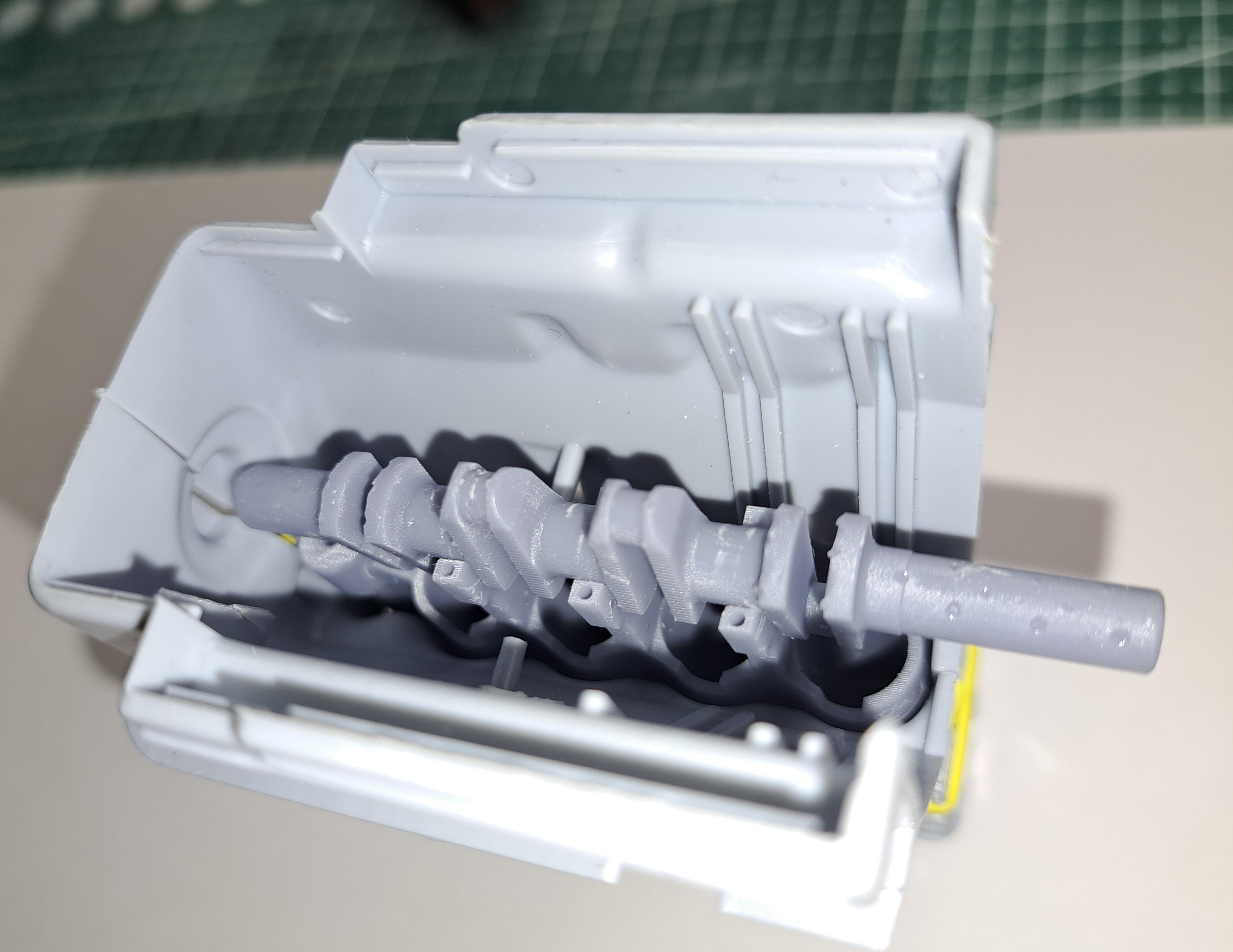
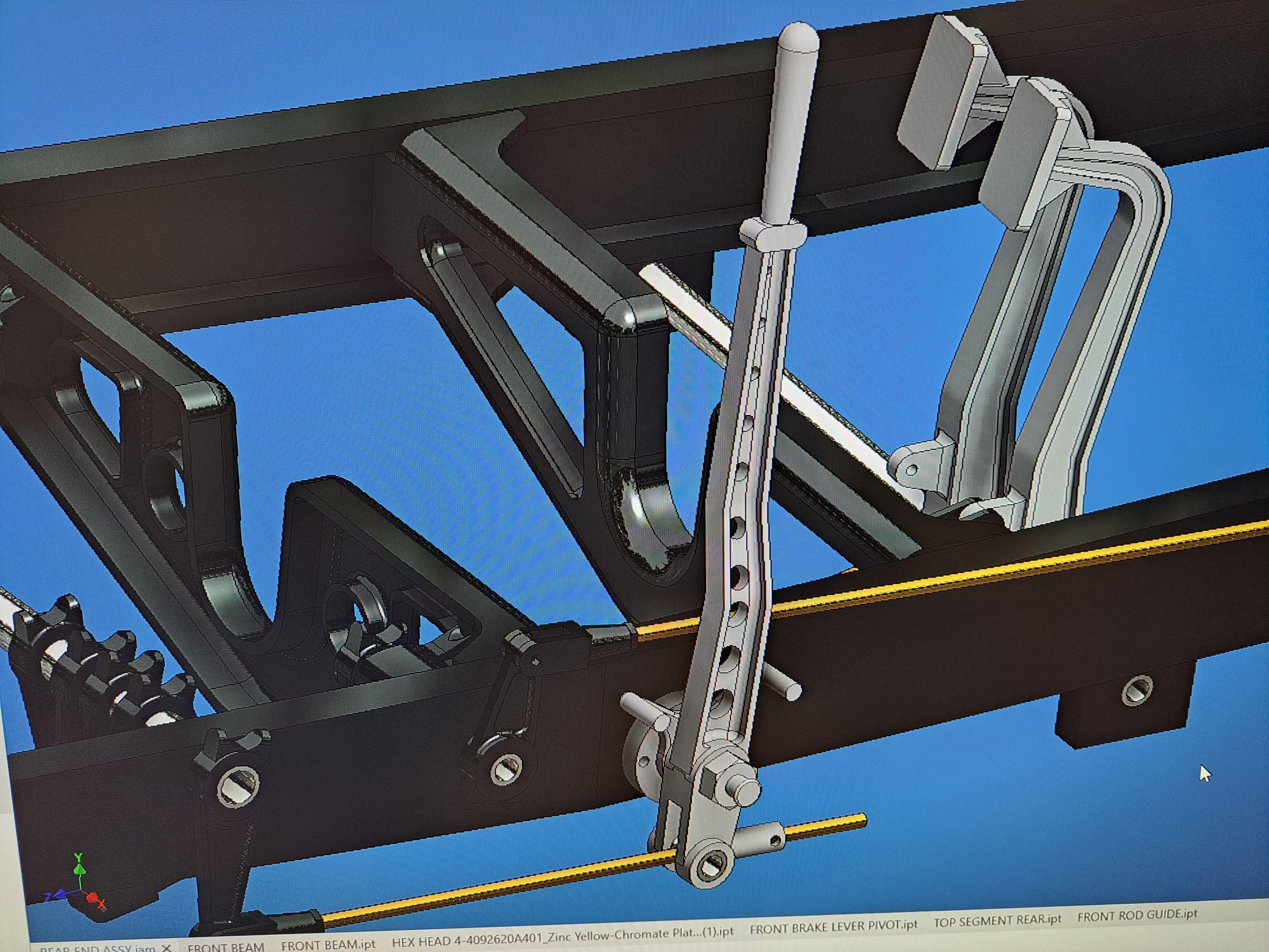
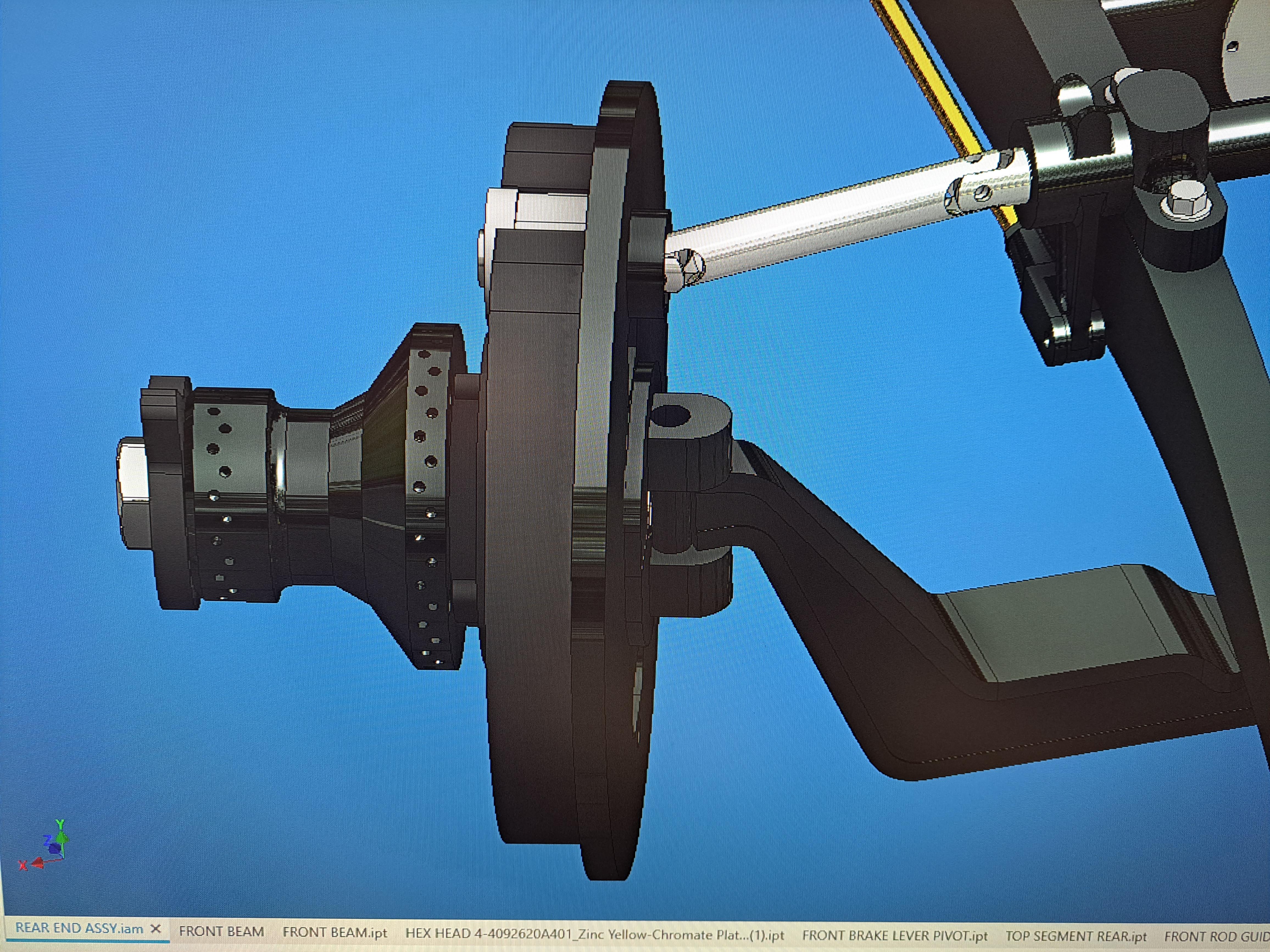
Ok, so I finaly finished modeling the brake linkage and all the parts that need resin printing are sent out. It took me a while to figure out how the system works but know it's ok. When you press on the foot pedal, the hand brake doesn't move and vise versa. It was just a question of mounting a pivot tube over a pivot shaft 20230718_221136.mp4 the pivot tube (in black) over the pivot shaft (aluminium). I also finished modeling the main bulkhead (firewall) with all the brackets to attach the steering column, dynamo, oil tank and dashboard. There is also a smaller bulkhead frame that is attached to the body. Fun fact, these 2 bulkheads where made out of magnesium, quite adventurous for the time as magnesium is explosive. I worked on a dashboard fabrication line for a GM car 15 years ago and I remember it was a big safety issue even with robots doing the majority of the part handling. all components printed (the part over bulkhead is actually a locating jig to help me glue the various parts in the proper location. a bit of assembly on the bulkhead And l finally started modifying the frame rails by removing certain moulded features such as the fake brake linkage levers which will be replaced by real ones and the steering column mounting bracket which will be replaced with a more accurate one. I'm also drilling a few holes for various pivots.
-
Thanks Bugatti fan, I already have some wires like that but I find them to stiff. The good news is the Italeri is willing to send me a good length for 5 euros.
-
I'm not familiar with this, could you please elaborate ? Thanks
-
It's actually silicone. I contacted italeri, hopefully they can help.
-
Hi all, when I did the Alfa from Italeri, the kit came with a small coil of 1/16 dia rubber hose. I didn't use it all on the Alfa but used the rest on this build's fuel line. I'm trying to find some more but all my searchs have failed. Any body know where I could find some? I was about to write italeri to see if they could sell me some but I would like to cut the middle man. Here's the tubing in question.
-
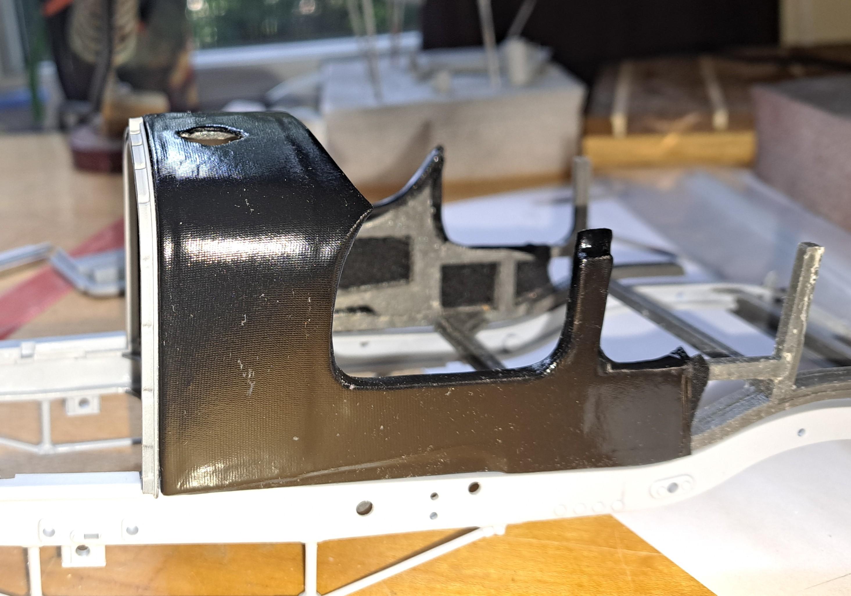
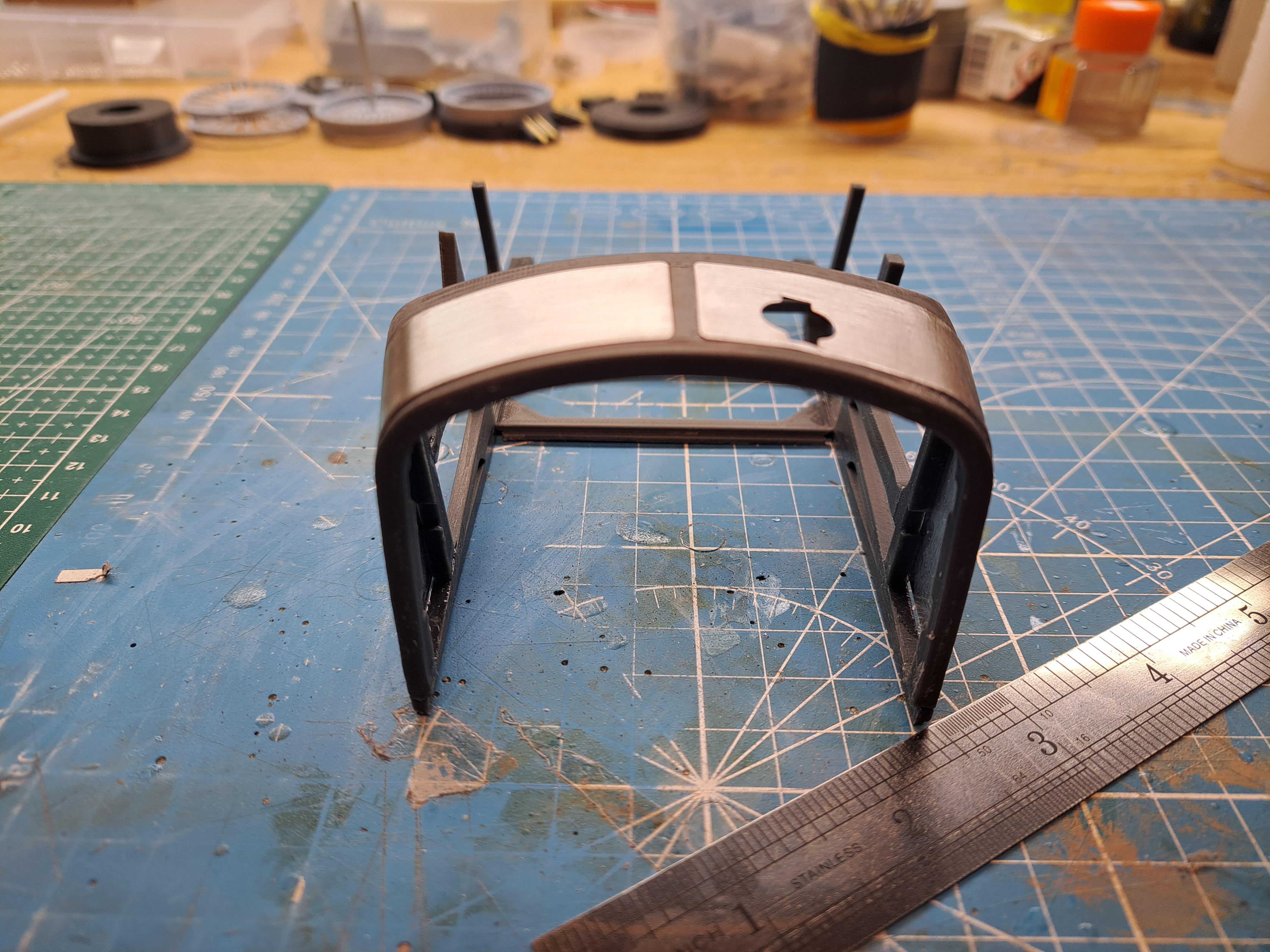
My first test bulkhead, the shape is not quite right yet but almost. Once painted aluminium, l'll add polished aluminium curved sheets with the bolts. Should eventually look something like this.
-
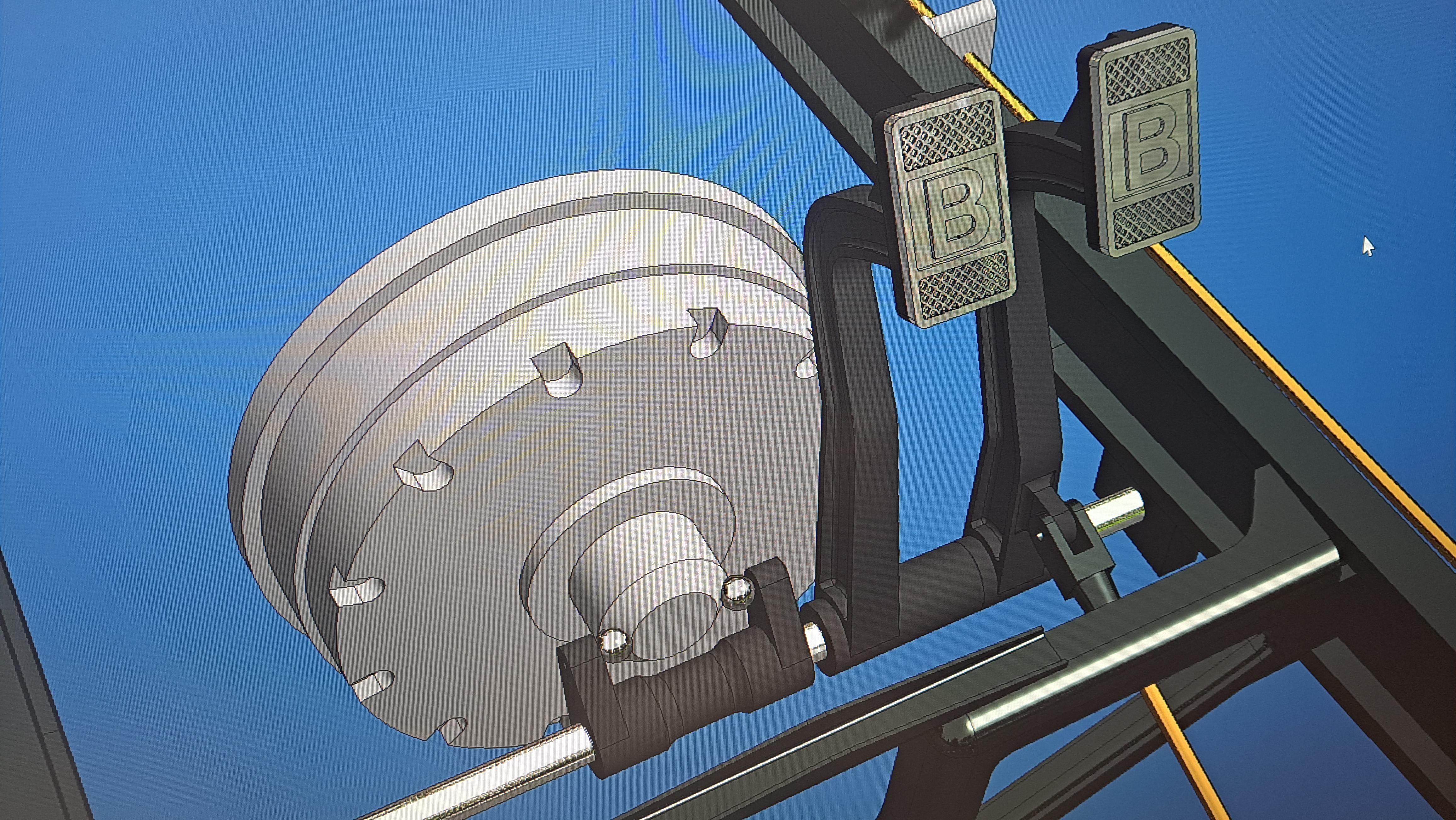
I reworked the pedal arrangement and incorporate the throttle between the clutch and the brake. I 3d modeled the firewall as per the kit's part but l'll try to get it closer to the real thing and print it. If it looks ok, it will replace the kit's firewall. I finaly got the drums right.
-
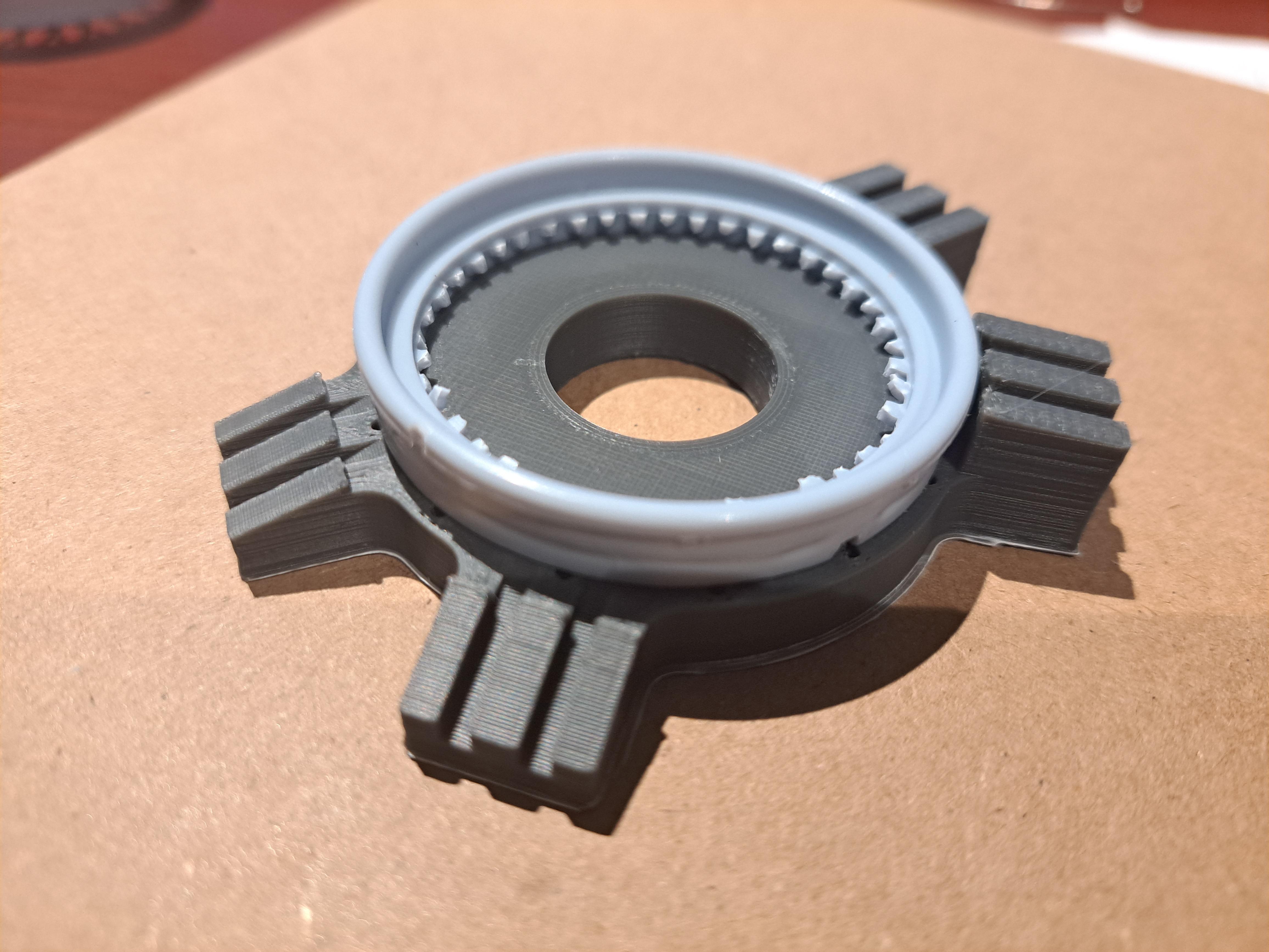
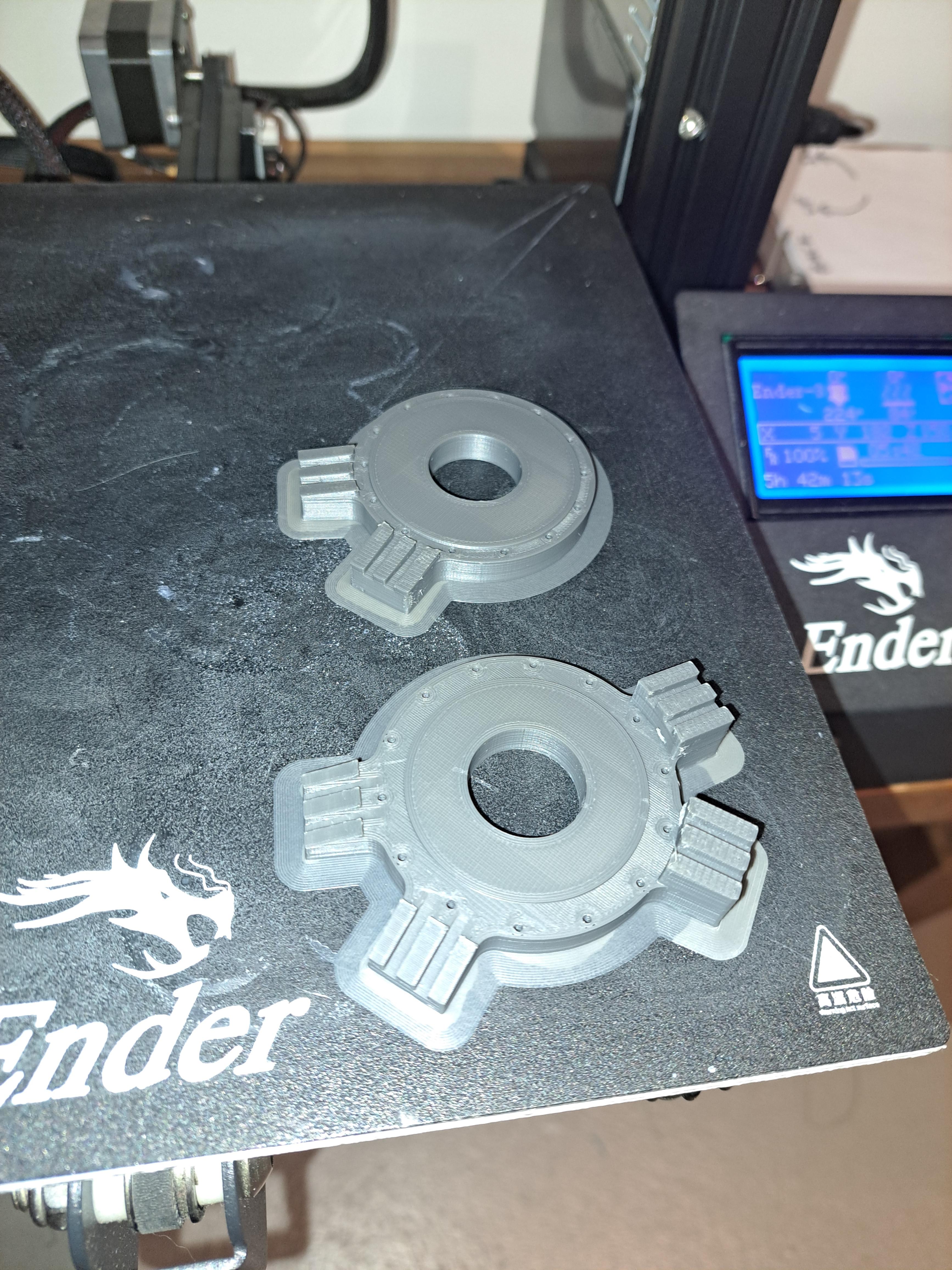
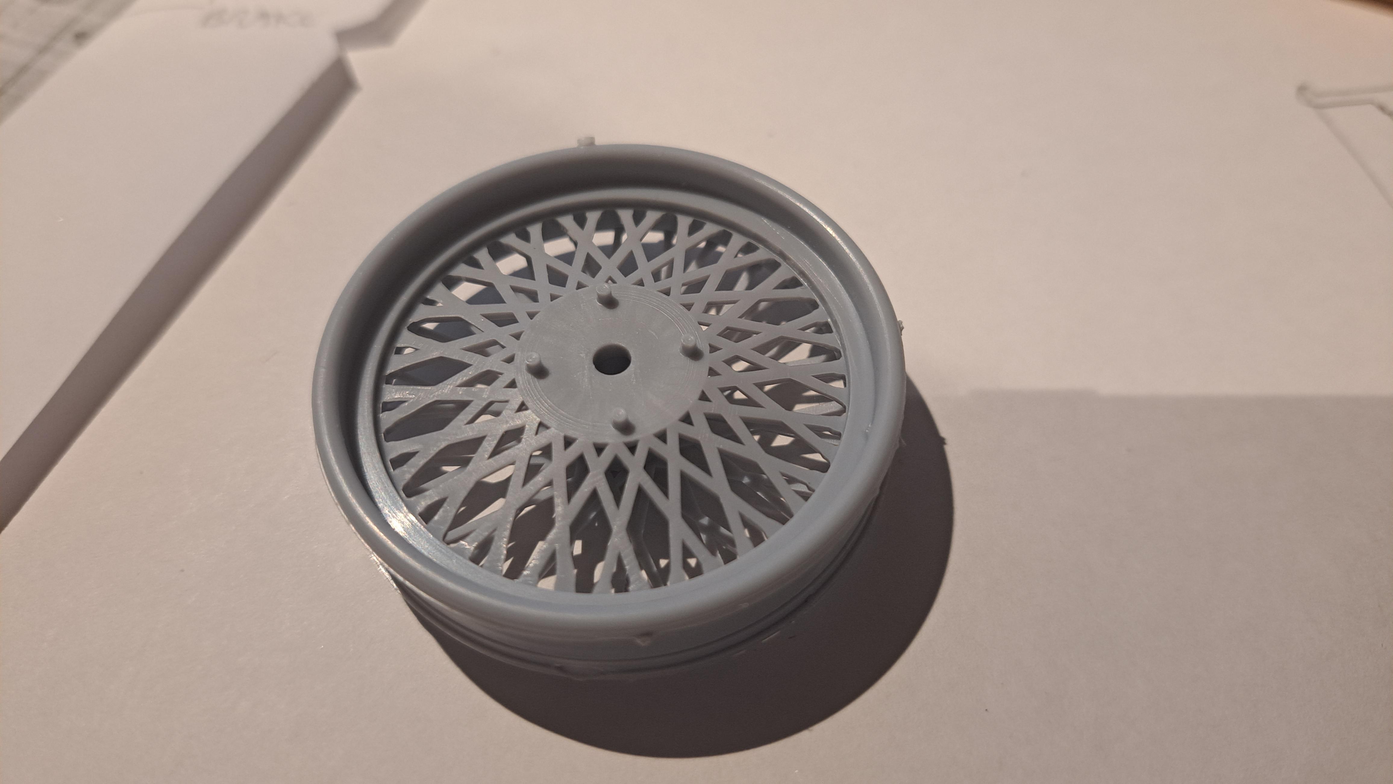
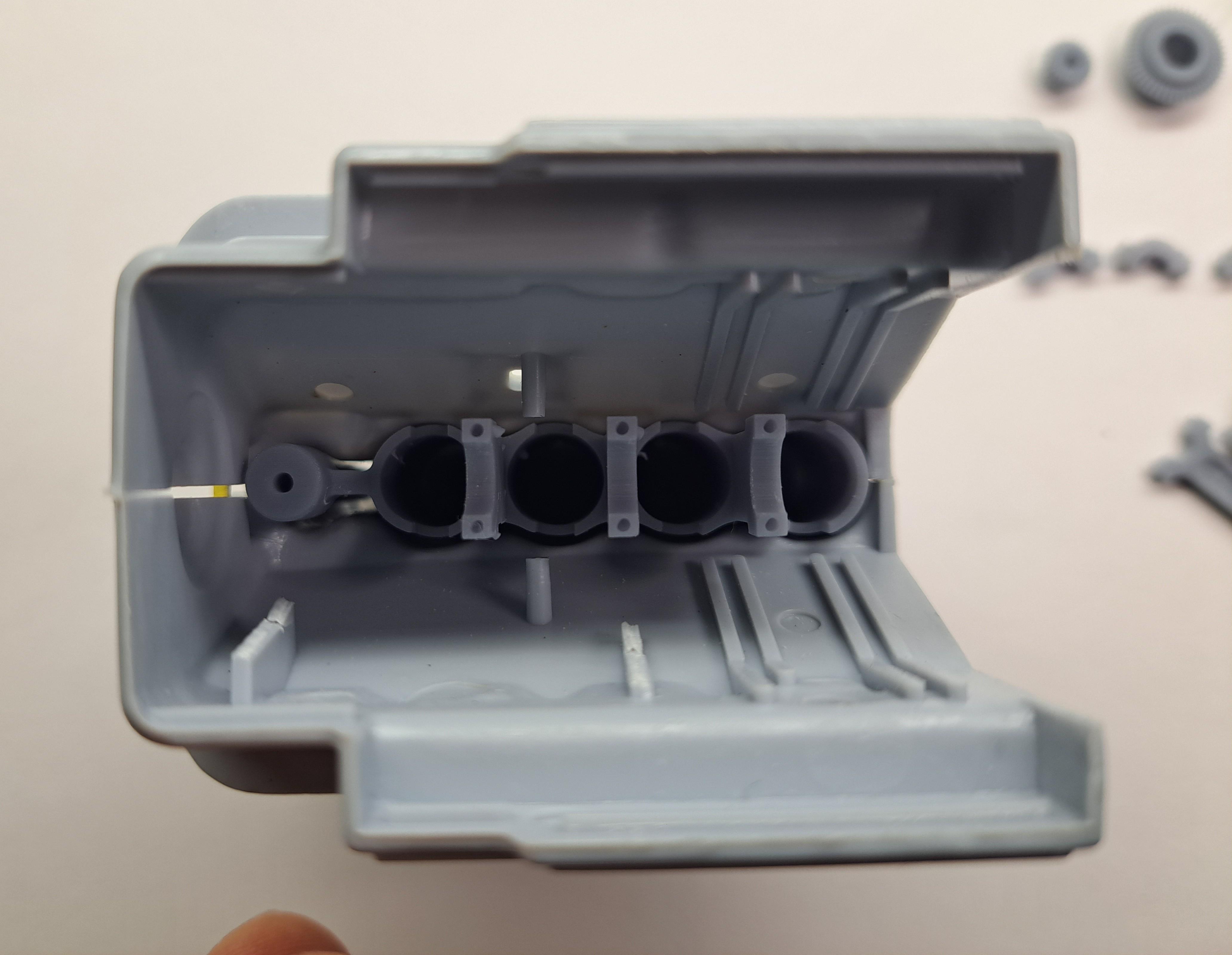
Printed the drilling fixtures for the rims. I just need to glue in small tubing in the appropriate slots to act as drill brushings and I'll be good to go.
-
Thank you Bugatti fan. Just to clarify, the only part l'm printing is the hub. I could have used the kit's hub like I did with the Alfa but it doesn't fit the new spinner hub l'm making and it basically didn't have the correct shape. The rim portion comes from the kit. And of course the wires themselves will be hand bent and hand laced. 3d printing has in deed upped the game but I still like to use the kit part whenever it is possible.
-
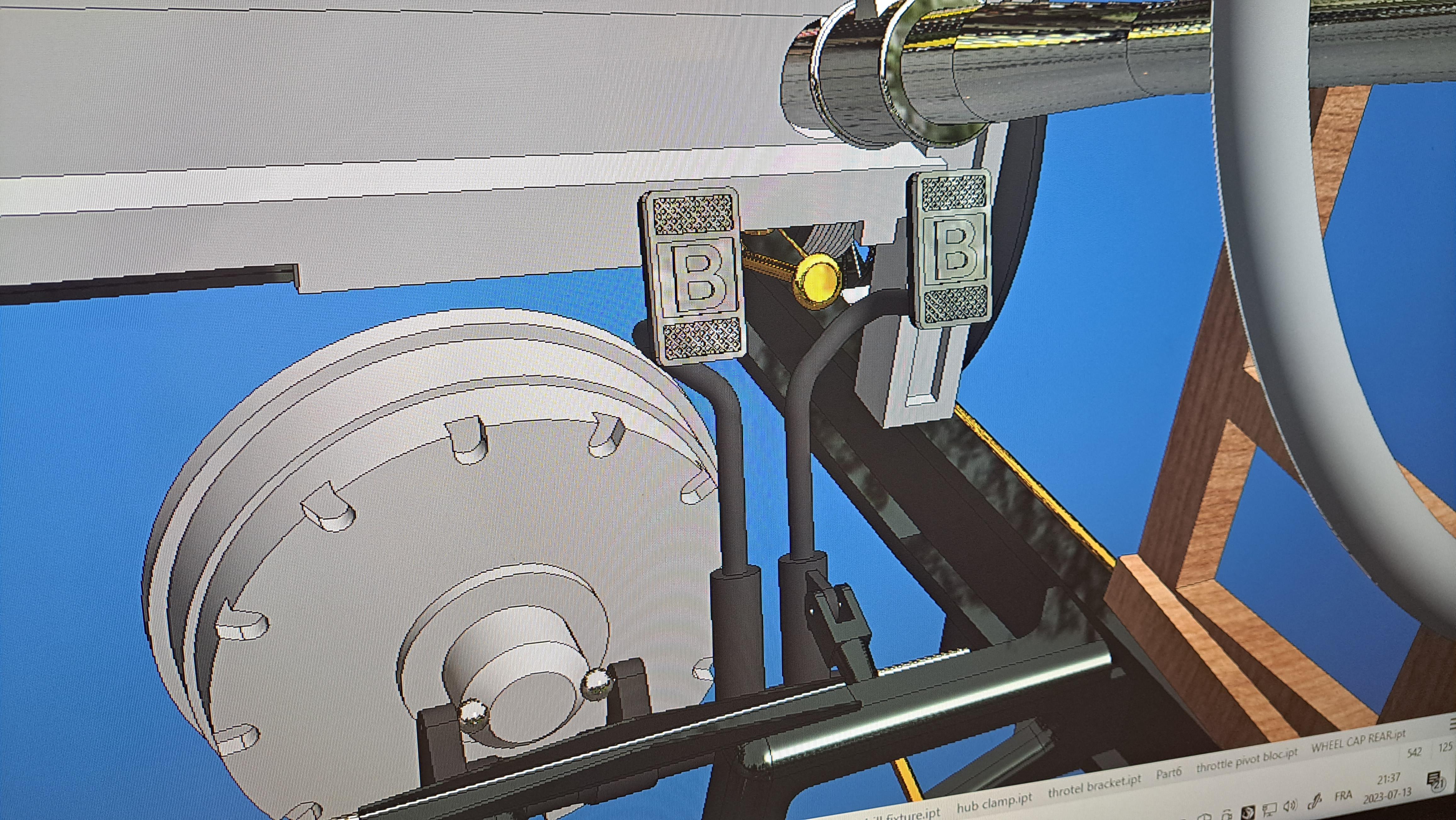
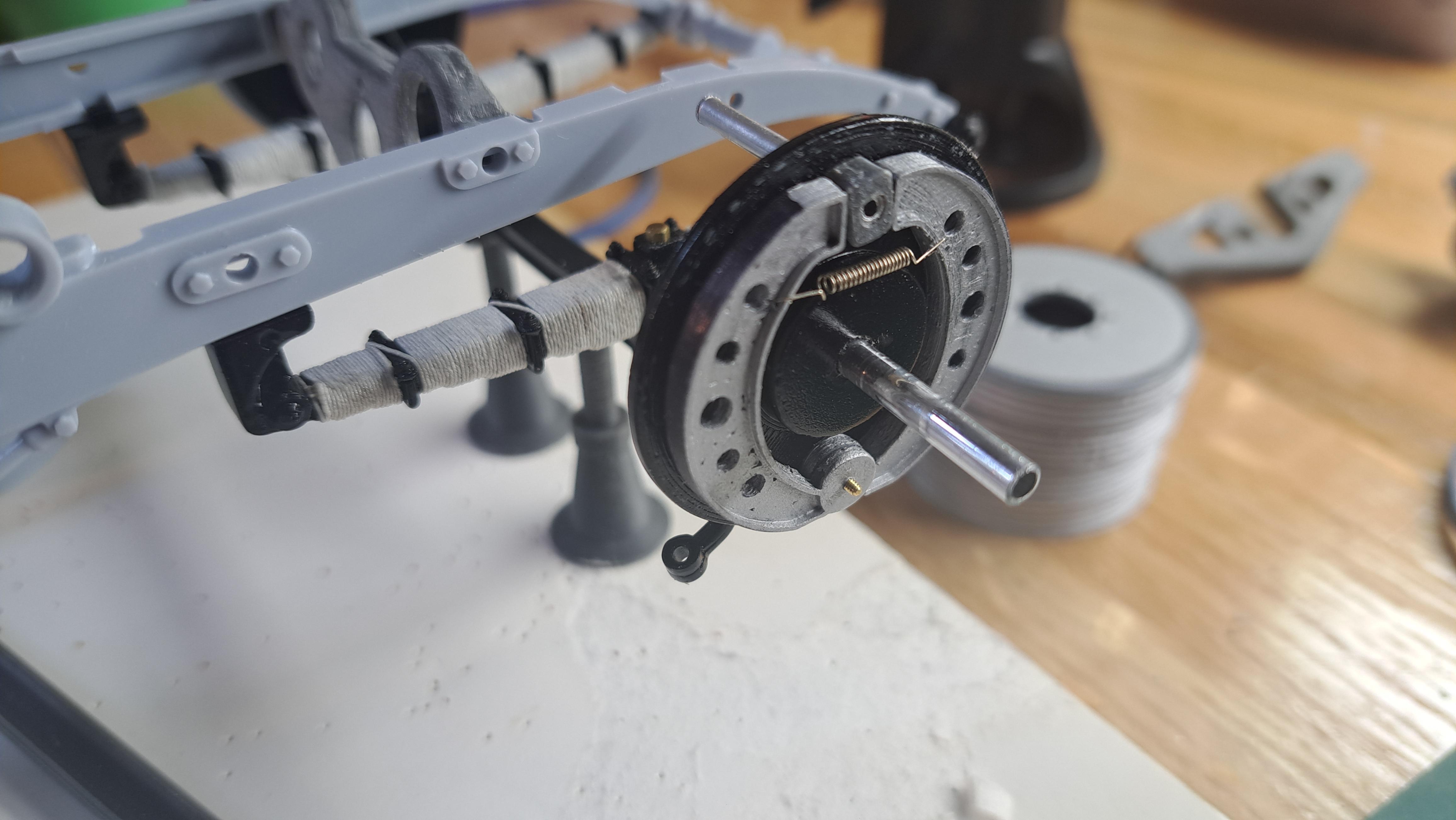
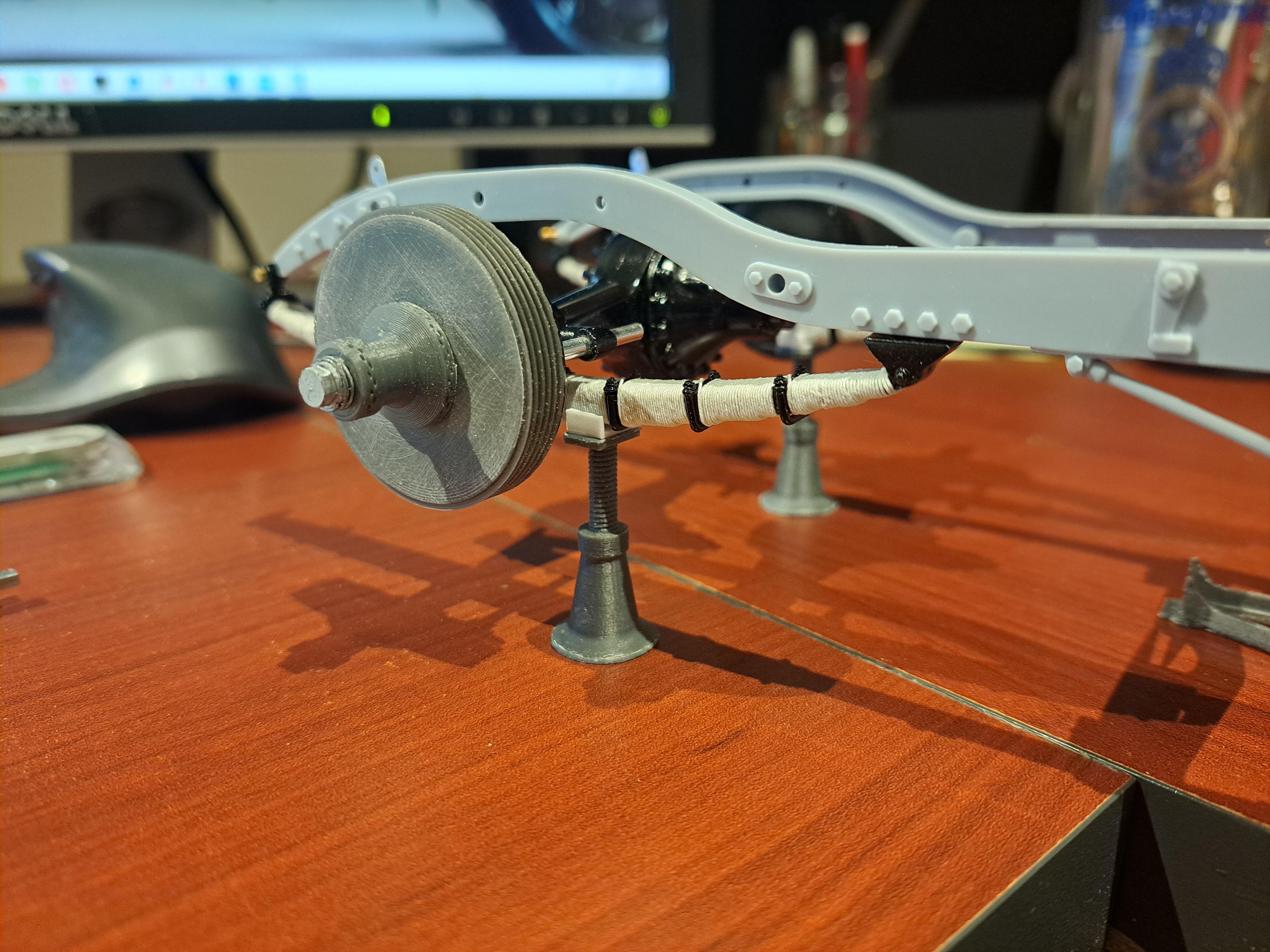
Did some more work these ladt few days. Added the front brake shoes with spring. Modified the rear shoes to simulate the double shoe setup (I missed that one). The real setup calls for one pair of shoes actuated by the foot pedal and one pair actuated by the hand brake. Started tinkering with the gear box and drive shaft. I 3d modeled the wire wheels. it's not 100% accurate but all I needed was to create the hole patterns on the rim so I could design the drill jig.The kit's wheel are not accurate, they have 1 set of holes on the outside rime and 2 sets on the center portion. In reality, it's 1 set on the outside rim, 1 set in the center and 1 set on the inside rim. The hubs will be printed. And the jig I'm still not happy with the brake drums I printed. New one are being printed as I write this. I also added pedal pads with the Bentley 'B' on thems. And the clutch fork. That's pretty much it for now.
-
John, l'm using the kit's original frame that l'll be updating so I can fit the brake system's various pivot shafts and whatnots. The reason I 3d modeled it was to be able to fit the brake linkage. I mainly use a dial caliper, scale protractor, a ruler and my eye ball to copy the parts. The Airfix's body supplied with the kit is a simple molded tub.
-
Big John, what I meant was that 9 months ago, l modeled the wooden body using the kit's plastic body as a reference and a few weeks ago I modeled the frame using the kit's plastic frame as ref without ever checking one with the other. I'm just surprised that my models fit together.
-
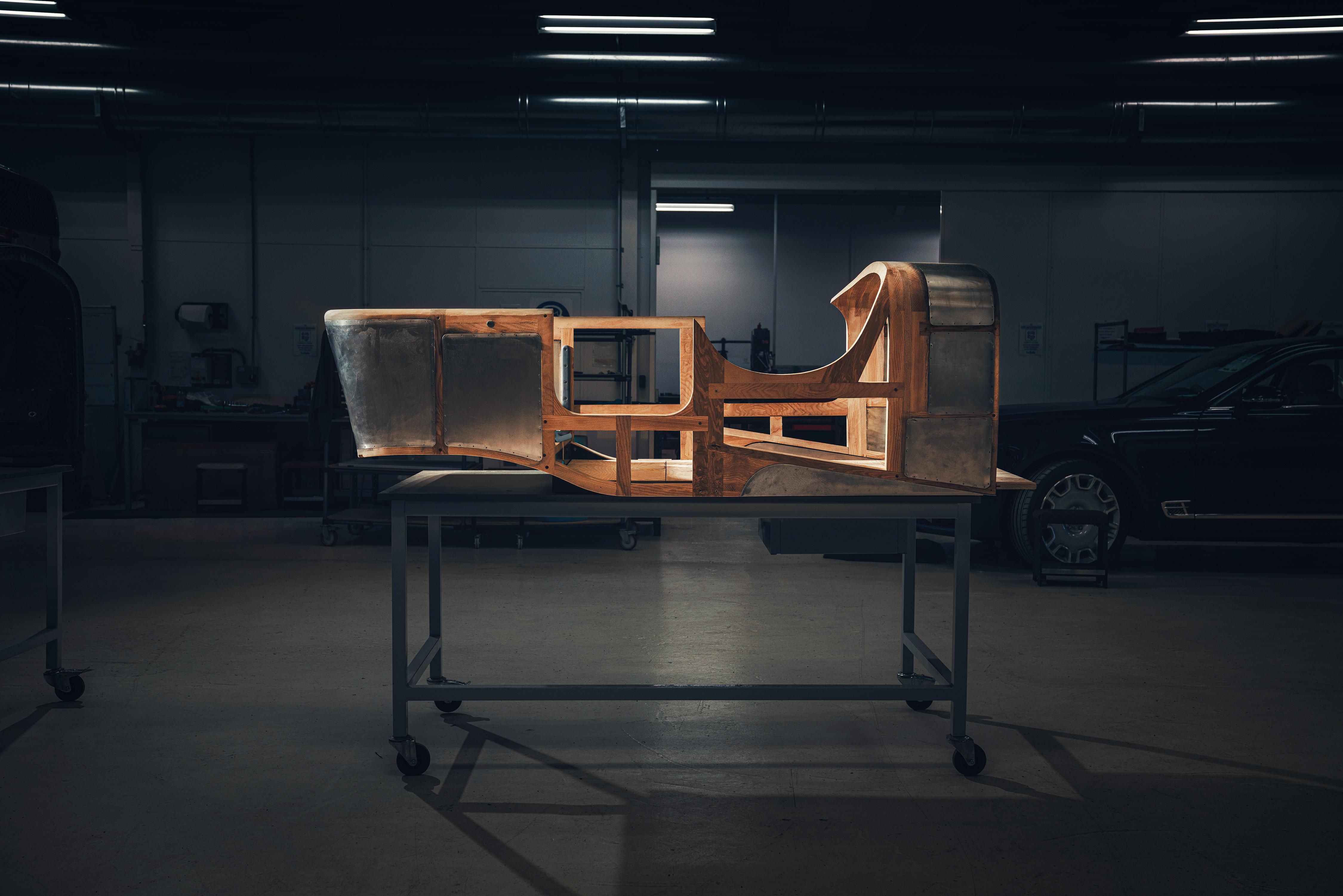
I mated the wooden body with the frame and the fit is surprisingly good considering that they where 3d modeled 9 months apart.
-
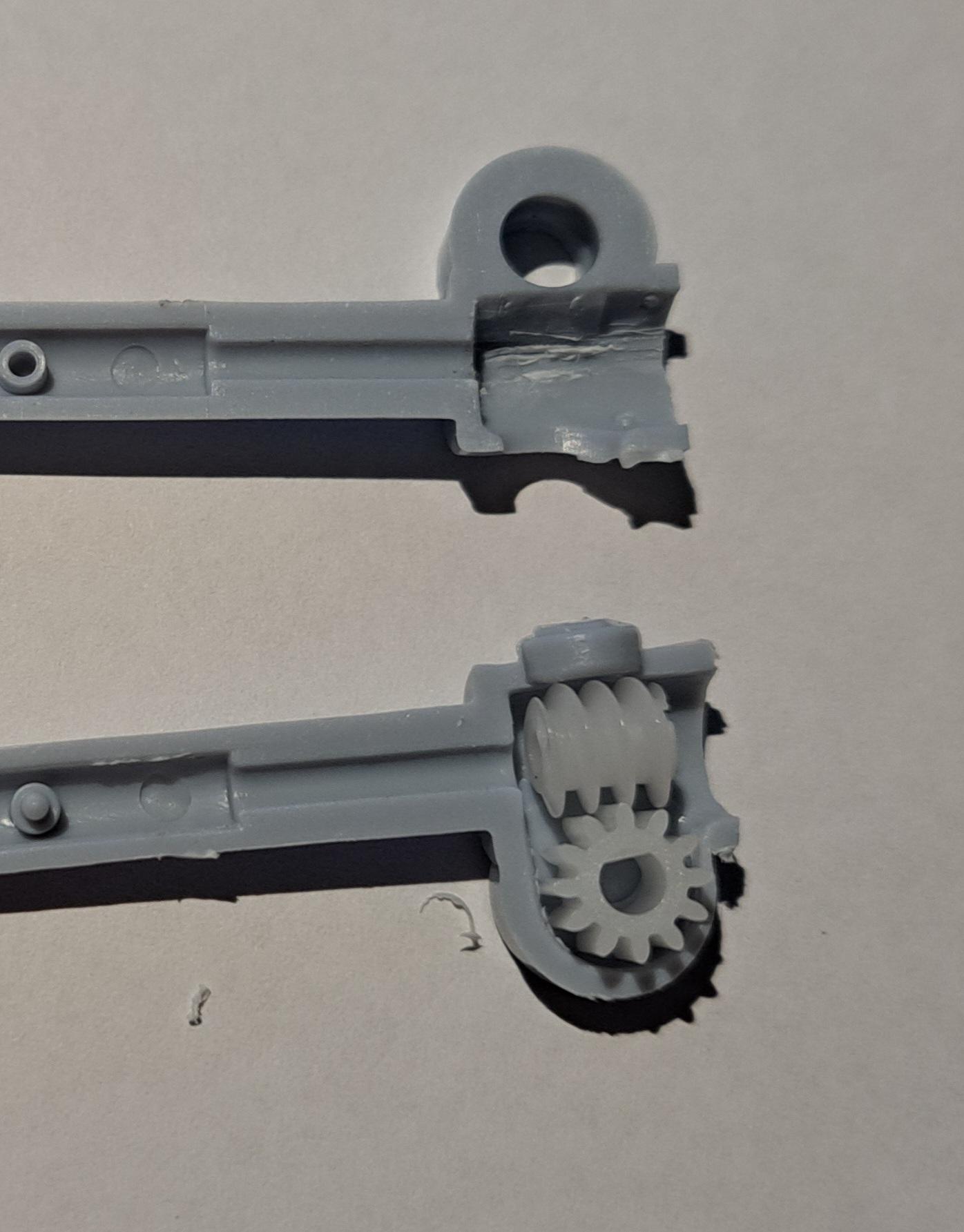
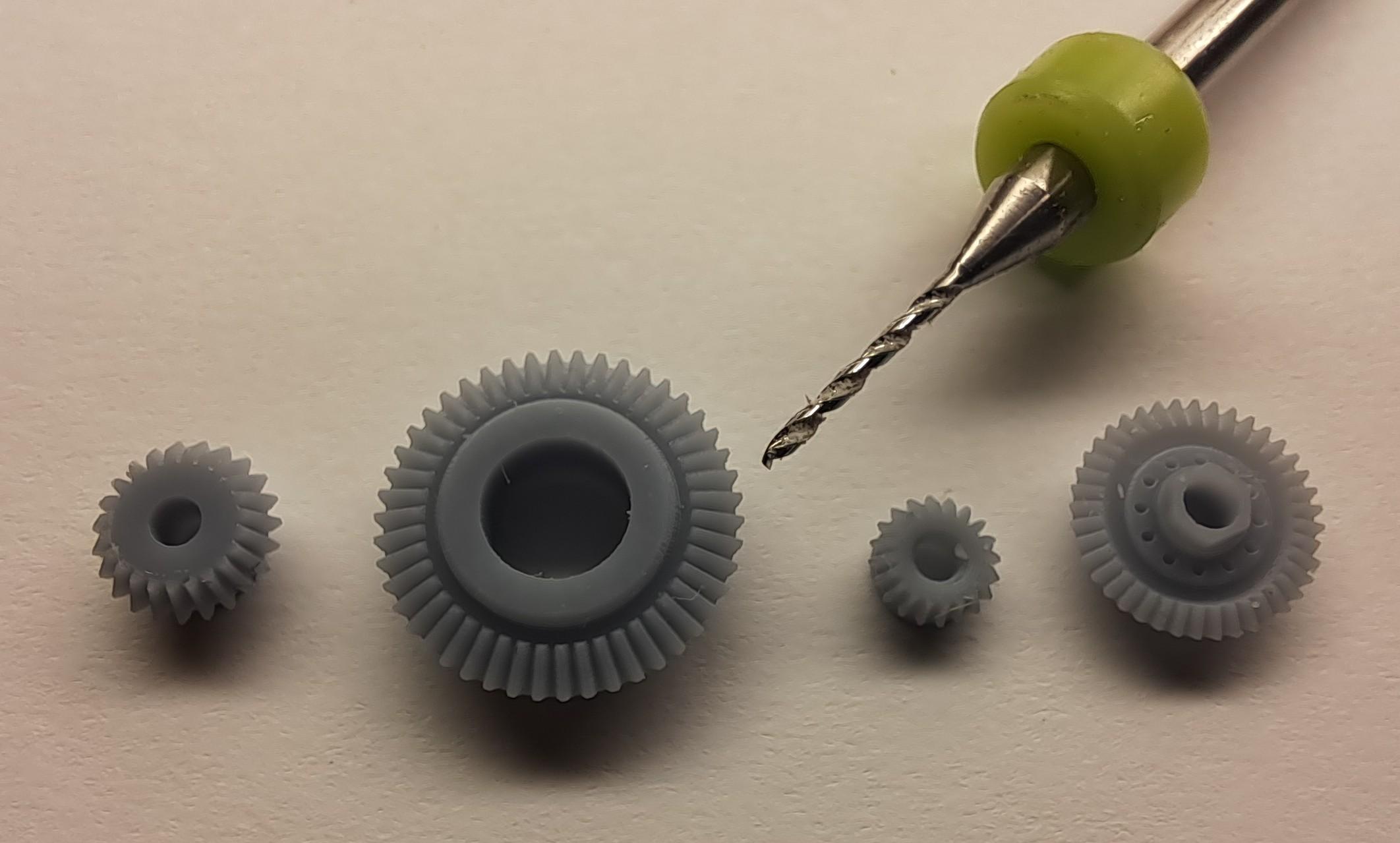
I've pretty much finished the brake linkage modeling, l should be ready to send these parts to resin print next week. 20230706_222859.mp4 I decided to tackle the steering box. To my 'not so big surprise', the steering wheel is not linked to the wheels on this kit, in other words, the front wheels won't steer by turning the steering wheel. That's not acceptable. So I decided to add a worm gear combo to fix this. Here's what the kit provides what's surprising is that there seems to be a space already moulded in to receive a worm gear. Could it be that in the past, the kit provided something for this? So here's what I wanted to do and after final fitting and the result 20230706_214017.mp4 I should be ready to start the frame rail modifications soon and should have a glued up frame shortly.
-
Thank peteski yes, it was effectively a C section frame hand beaten on special toolings.
-
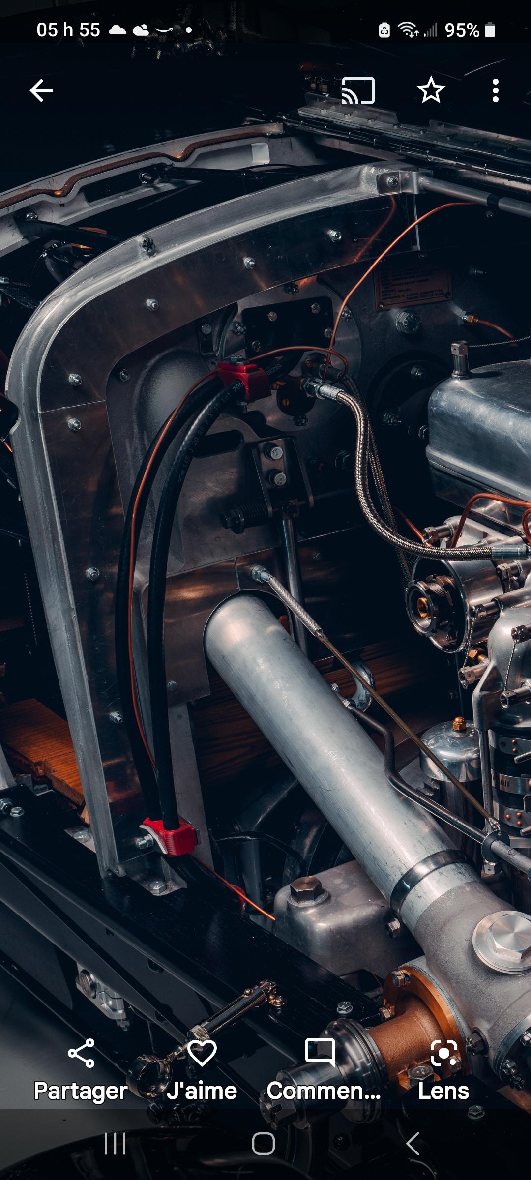
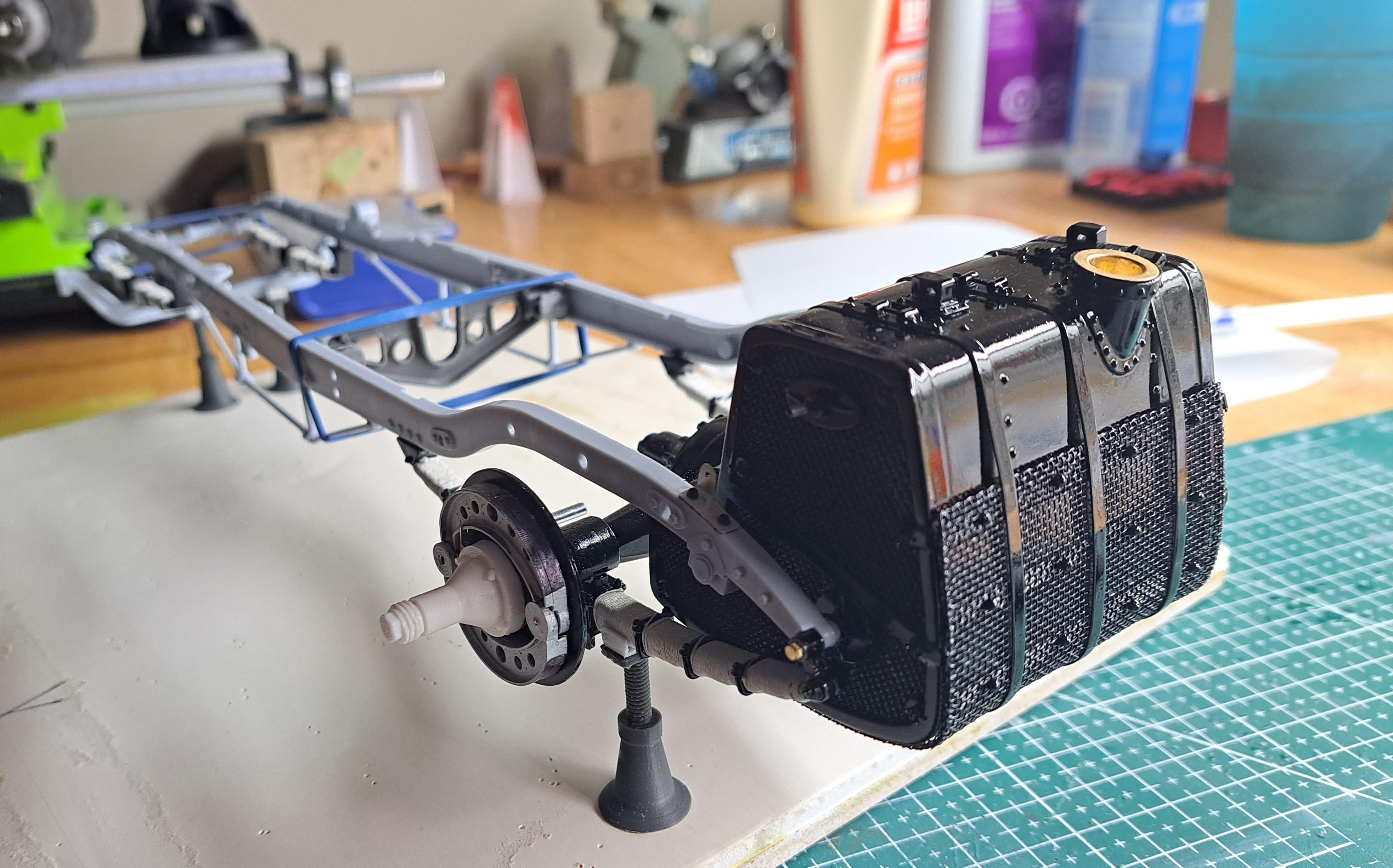
Test fitted the fuel tank in the chassis, it fitted fine. I also received all the internal parts for the engine, there's a lot of fitting to do but the result should be good.
-
Thank you absmiami, I didn't know about the Delage. l have no doubt that these type of systems must have been quite scary to use let alone ajust. So many pivots and levers but, from a pure design stand point, you have to admit it is way cooler then a simple hose filled with fluid. It's a lot more fun to 3d model this then a simple hose and a lot more fun to do in scale.
-
I'm almost done with the brake system modeling. I thought the italiens where gutsy designers, but the way these bentley boys did the front braking system is beyond cool! They use double universal joints with the pivot points properly located to permit both an up/dw mouvement of the wheel while still being able to steer. Quite a nice design. 20230701_221945.mp4 I started modeling the handbrake system, and if all goes to plan, it should be functional And finally, I printed some small ajustable candles, I wanted to see if I could print functionning threads, and it's possible
-
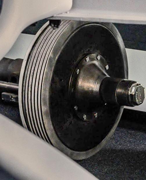
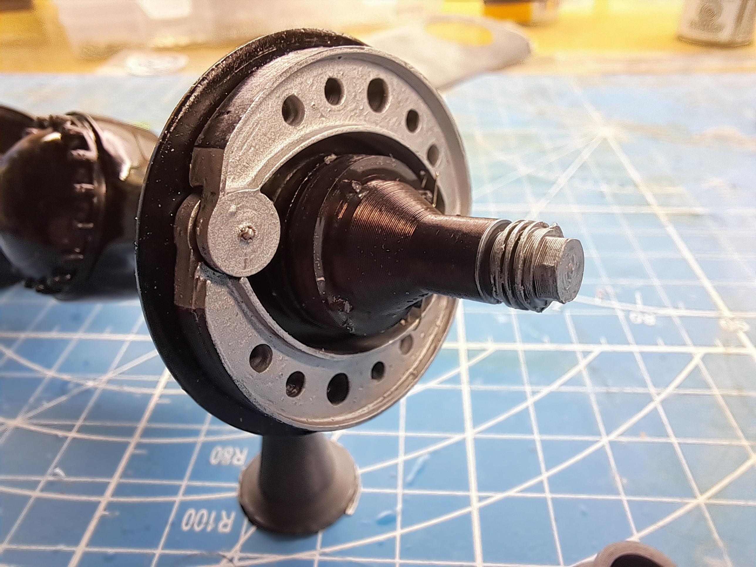
So, I've been working alot on the rear drum and spinner hub, printing like a mad man. Here's a crude sketch on how I think the set up would be like. here's a shot of spinner hub and nut mounted with the drum in place. We can clearly see that un like what the kit provides, the nut is just à threaded plate with wings. The chrome cap is not part of the dpinner nut but rather of the spinner hub. My version so far.

2.jpg.2f51bf4fd8542cc22d30111b6baae4c2.jpg)