François
-
Posts
489 -
Joined
-
Last visited
Content Type
Profiles
Forums
Events
Gallery
Everything posted by François
-
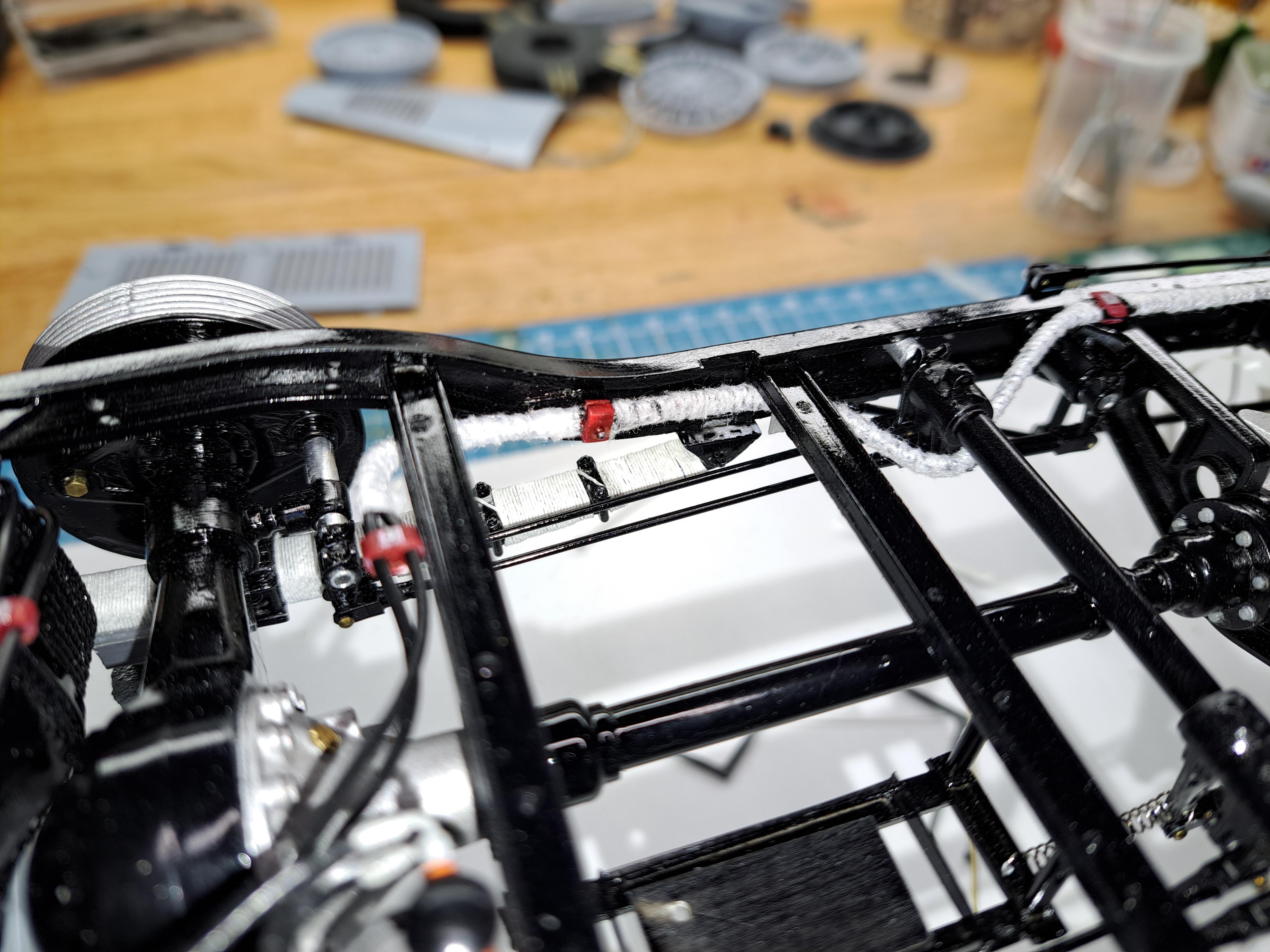
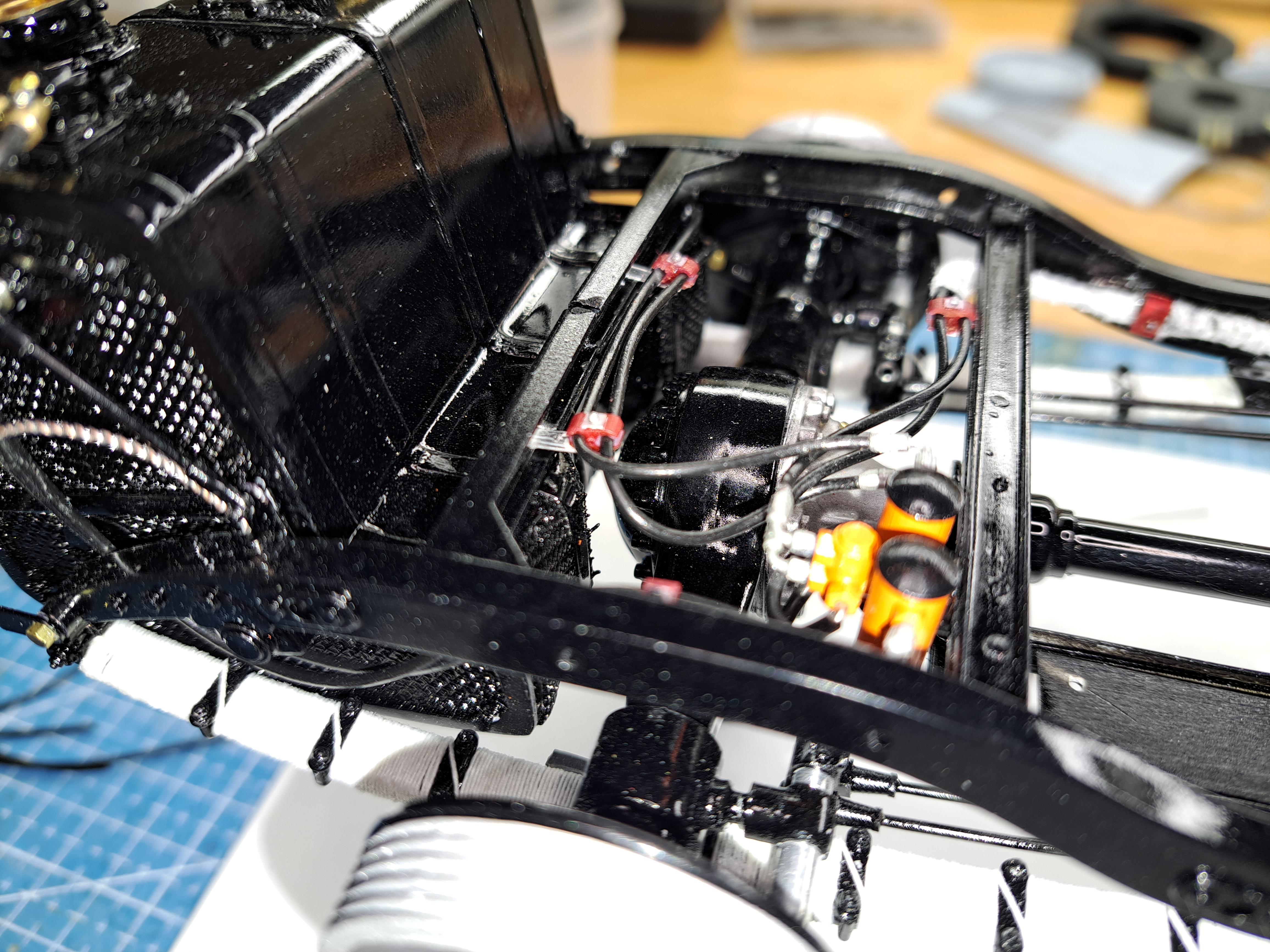
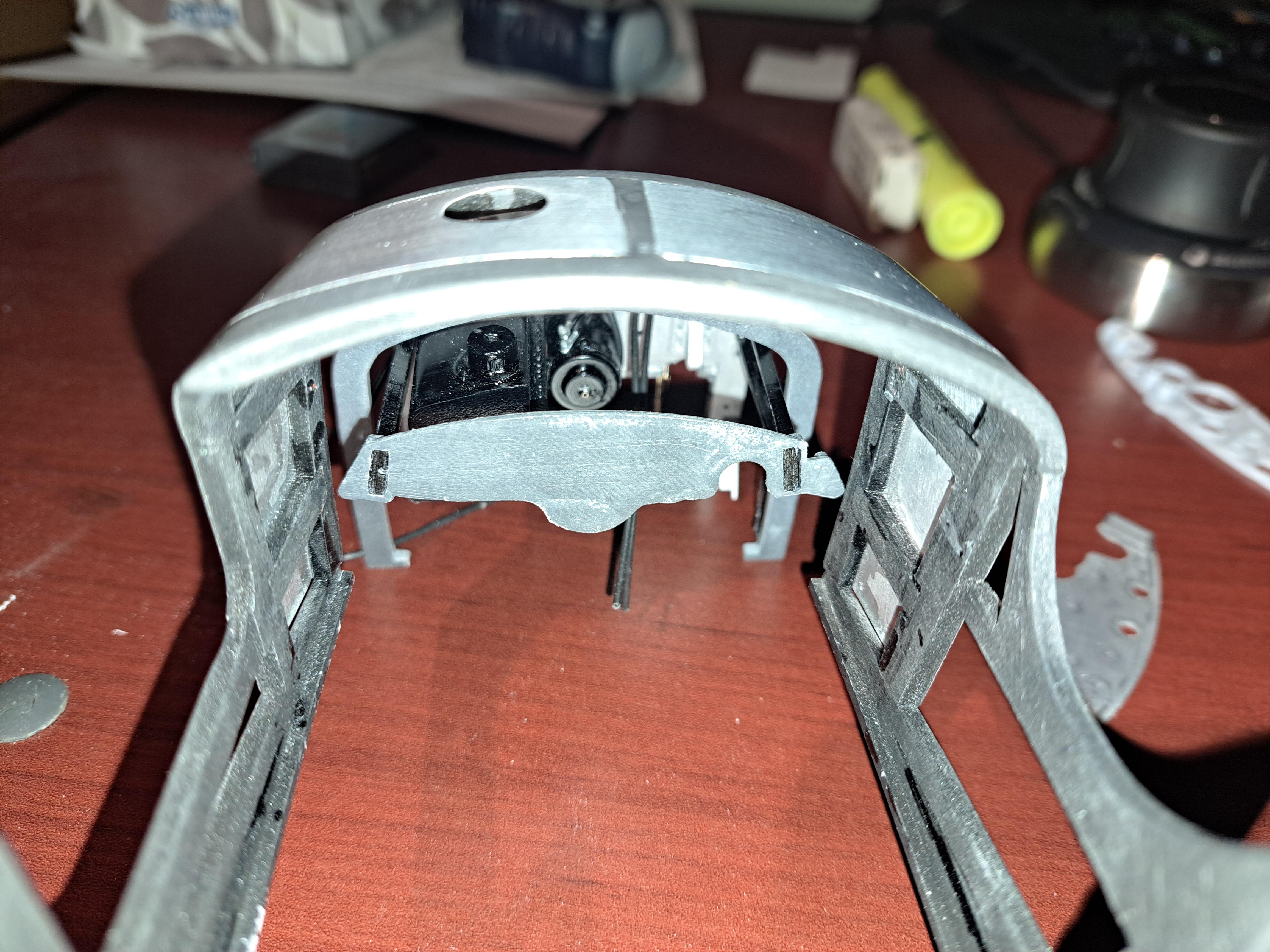
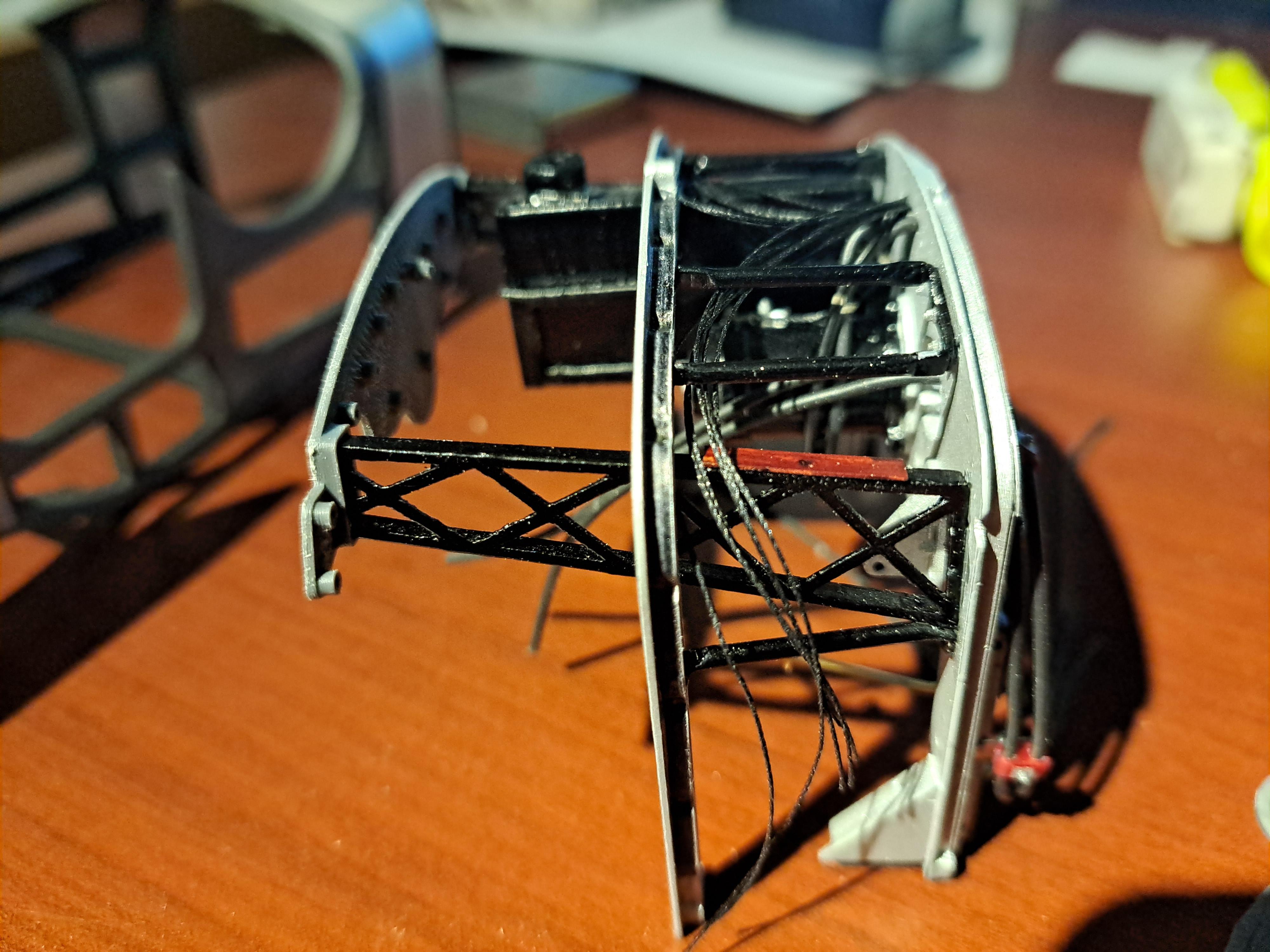
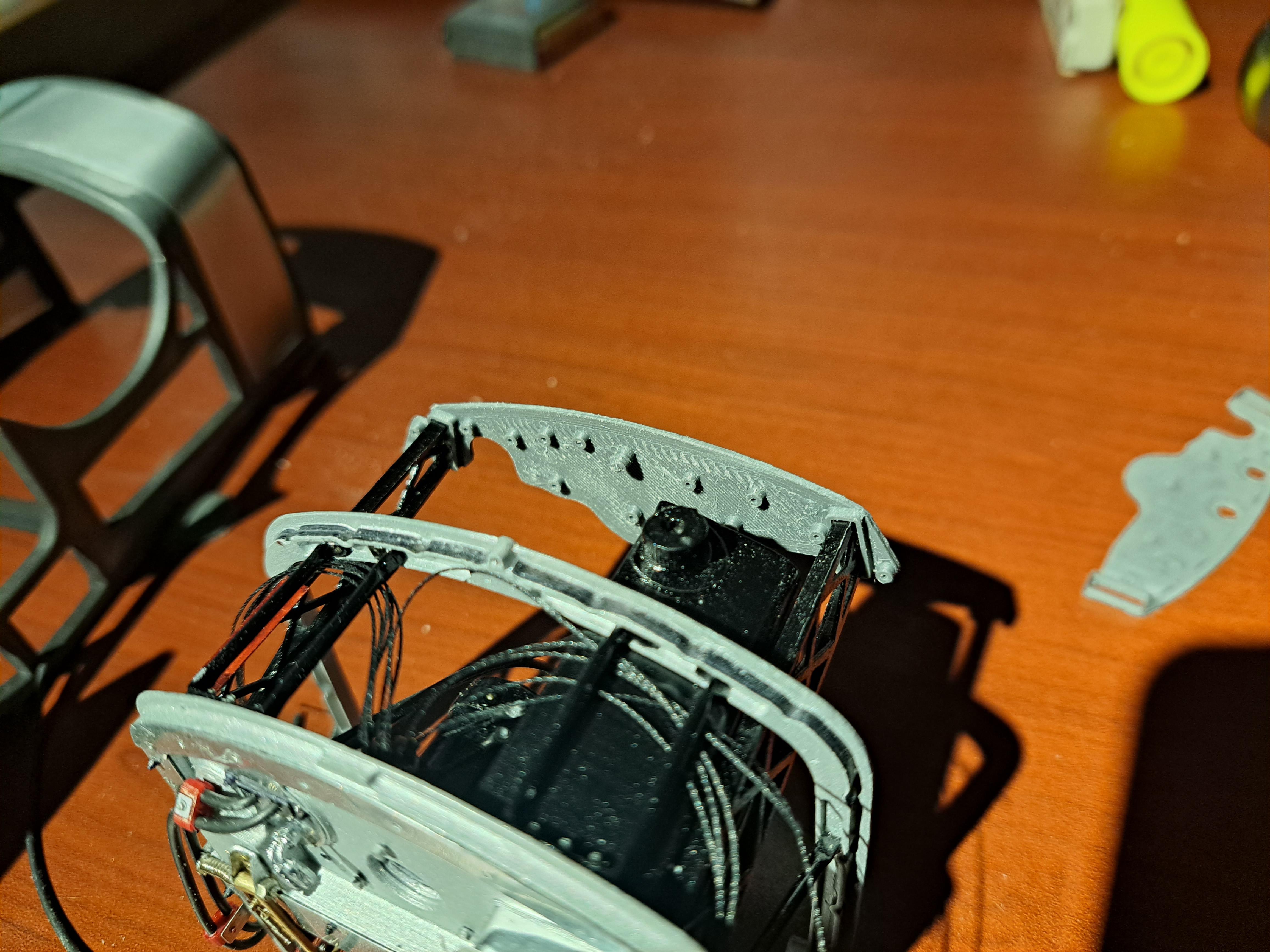
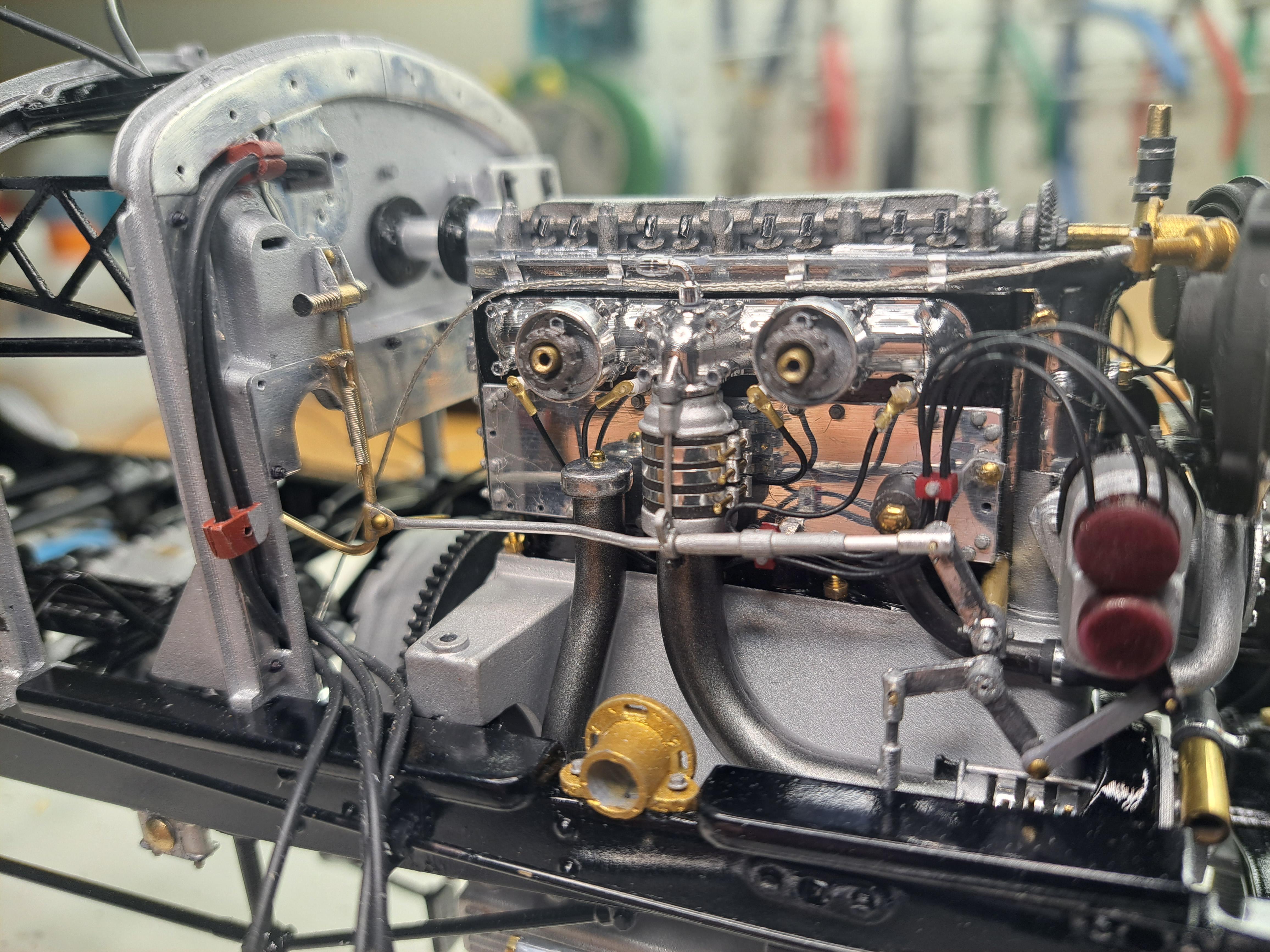
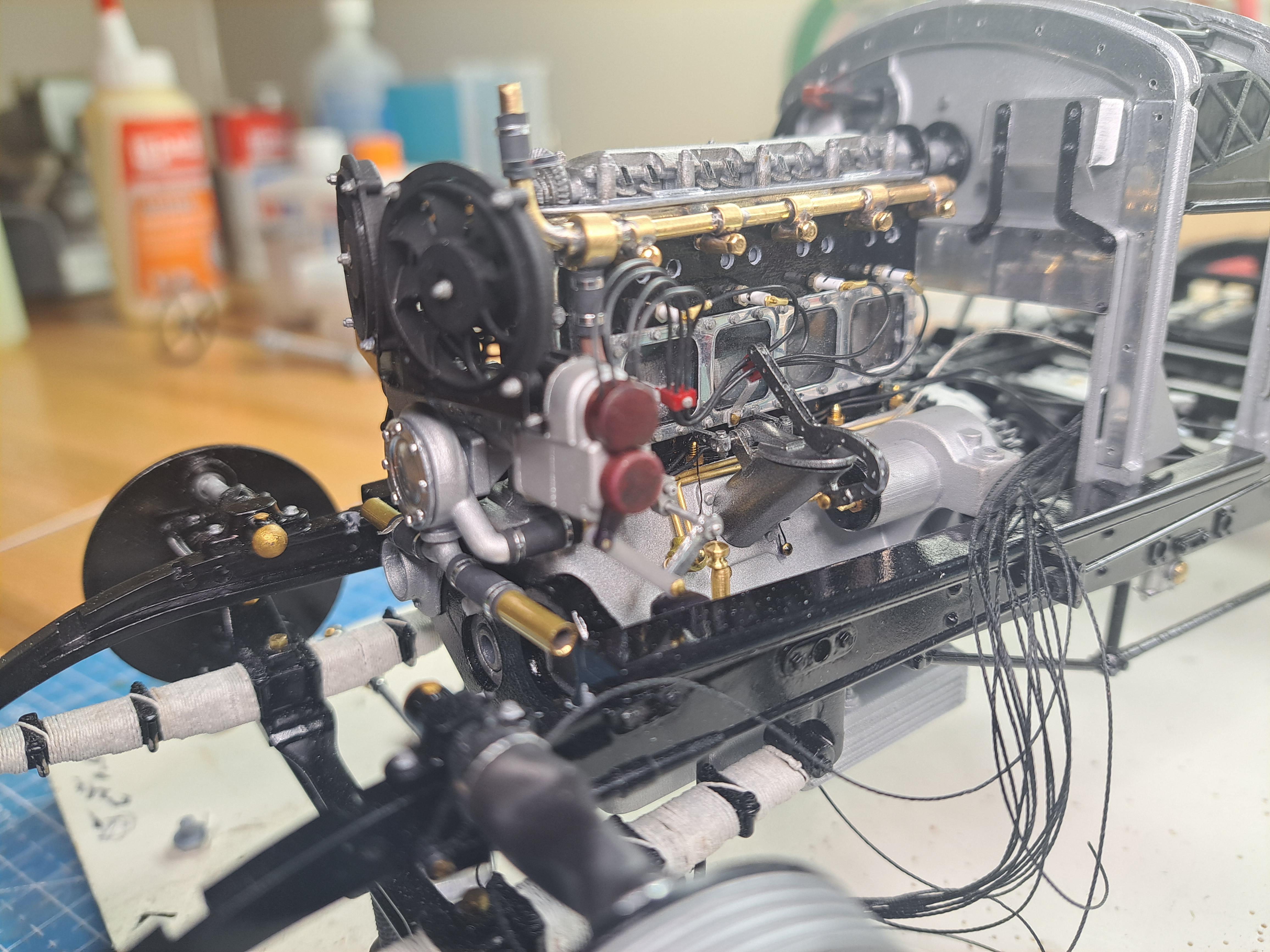
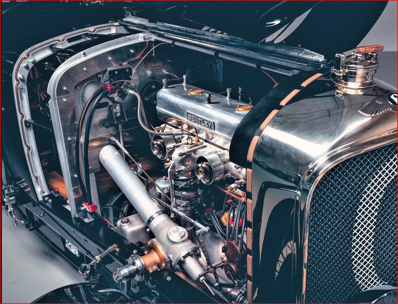
Thank you LaughingIndian and Ace-Garageguy, your comments are much appreciated. When I started this build I had a vague idea of what I wanted to do and where I wanted to go with it but frankly, I didn't think I would go this far. Like I said in my last post, I'm just about ready to install the engine but I've hid a catch-22. I can't install the engine before finalizing the hose/tubing/wire routing, but I can't finalize the routing before installing the bulkhead assy, but I can't install the bulkhead before installing the ingene... see my dilemma? So I figured out an assembly sequence that permits me to get everything in place. It's tenions and complicated but doable. But first, I have to finish wiring the dashboard. Here I hit another snag. To do this wiring, I need to install the dashboard on the bulkhead assy but if I do this, I won't be able to eventually install the body because the dashboard is to wide. On the real car that's the way it's done but for some reason, I can't. It's probably due to the fact that I based my bodywork on the kit's body that might not be 100% accurate. So the solution I came up with is to print a dashboard back plate that is narrower so the body will fit and that has holes in the back to receive the different wires. The finished dashboard will be installed only once the body is in place. I might even glue the board to the body, that way I could remove the body to better show the details. Here are some pictures. Dashboard on bulkhead assy (real car). You can see the ton of wires and hoses. My bulkhead assy with a fraction of wires and hoses. The almost completed 3d model of the dashboard, the board will be made from aluminium. I'll try to replicate the swirl patterns on the front face. The bezels, switchs and knobs will be 3d printed. The body doesn't fit if the dashboard is already in place. Back plate solution, the body will fit over ity Back plate in place, you can see the small holes to receive wires. I made new higher candles to be able to flip the car once the engine and bulkhead are in place. here are some more pictures of the fuel line snd fuel pump install.

-
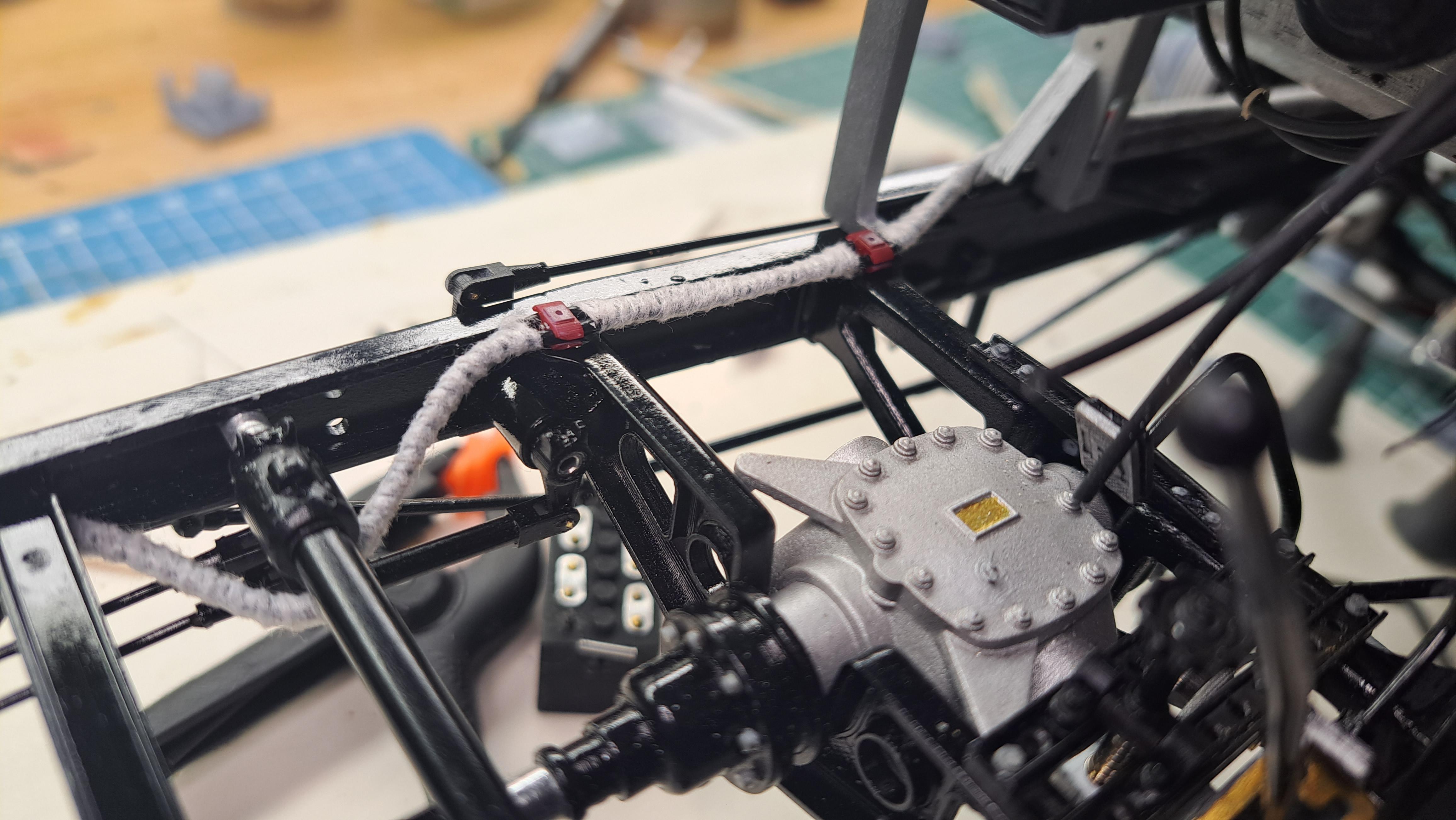
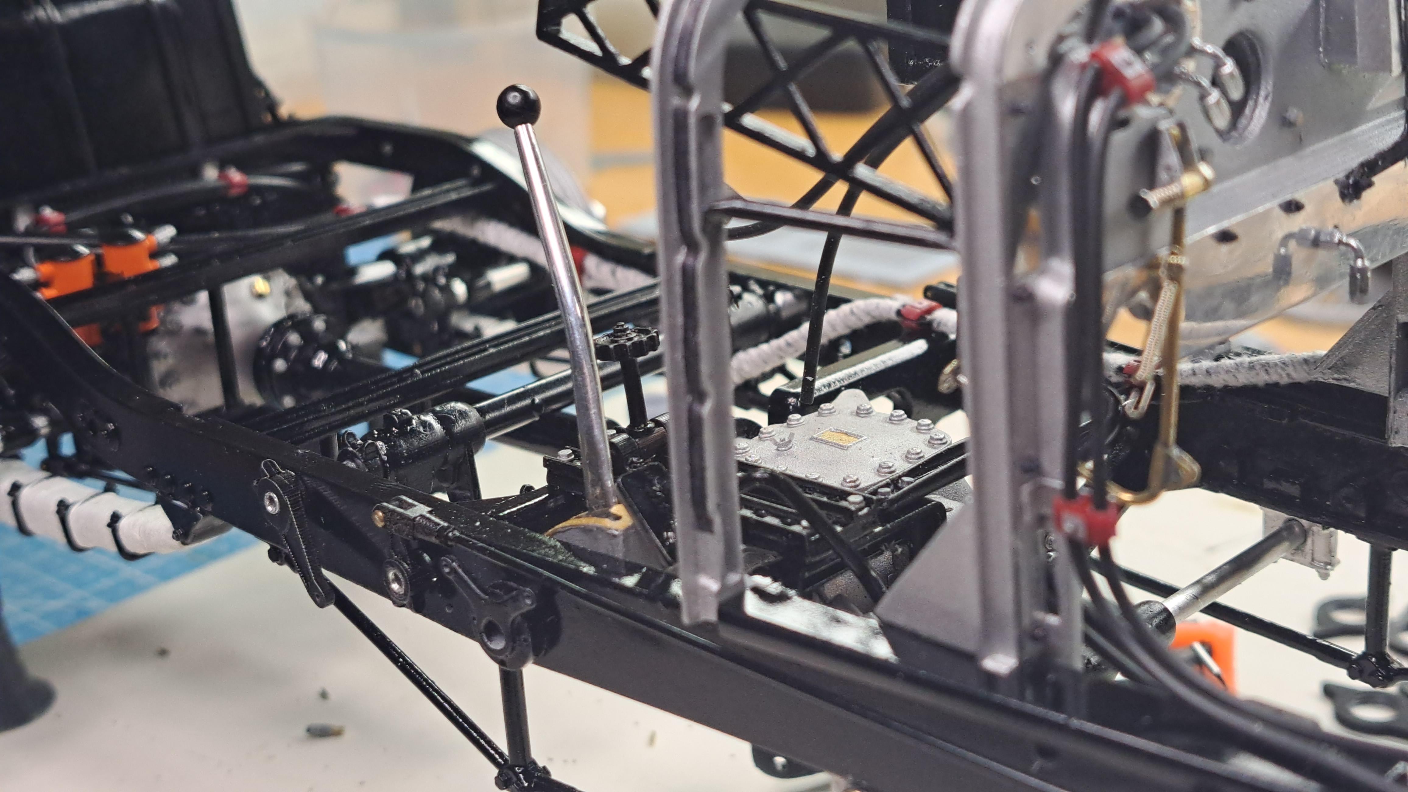
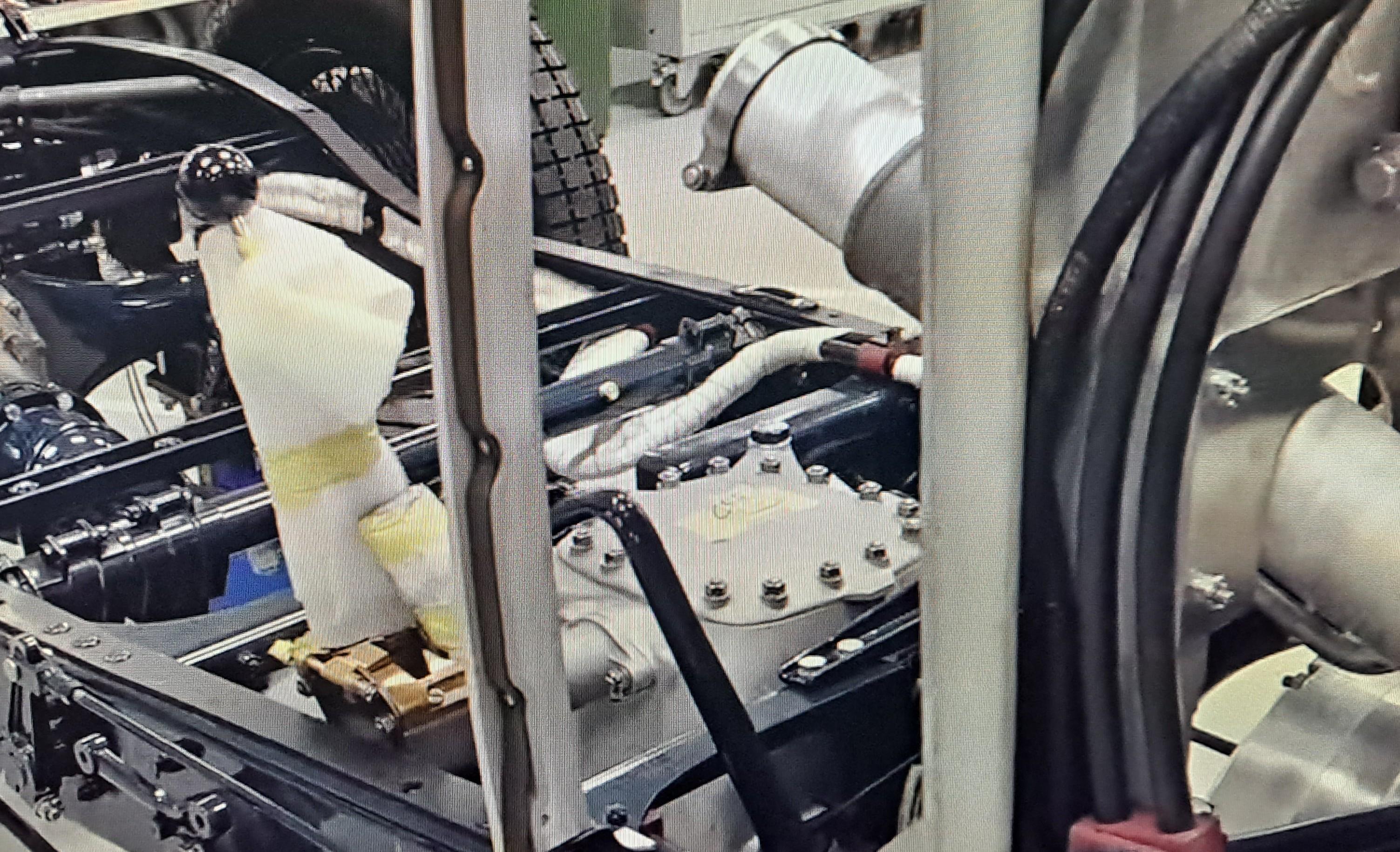
Ok, so I'm just about ready to install the engine on the frame but before I do that, I need to rout the fuel lines from the tank all the way to the front. So I decided to finish the fuel tank install and go from the tank to the fuel pump and to the from. On the real car, the fuel lines are coverded with a cloth tape that I imagine is fire proof. I tried many different type of tape but nothing worked until I remembered a medical tape used on a WW1 plane I did last year. It's called Hypafix, it's seems to ge made of some type of fabric l, is very thin and flexible. It did the trick. This is the tape. This is what I was aiming for. And here what I made.
-
I worked on the magneto linkage and after some tweaking and lever reprinting, I was able to assemble a functional mecanism. Now, it still needs to be connected to the stator shaft on the steering column but that will be much later. Here are a few pictures. 20231113_120750.mp4
-
The plug wires are done on the passanger side and with the installation of the oil filler tube assy, the oil management system is now complete. I'll try to complete the magneto linkage next. I really wanted these linkages to work but I'm not sure l'll be able to. In order to respect the scale, the levers are very small ans fragile. They break very easily. The worst case will have them glued in place and for show only. In other news, I had to redesign the wheel rim drilling jig. When I first modeled the wheels, I copied the lacing pattern of the Alfa romeo wheels but it turns out that the number of holes between a given pair of wires is different so the drilling angle is different. I also had twice too many wires on the inner most part of the wheel. I'll continue the wheel lacing as soon as I finish the engine.
-
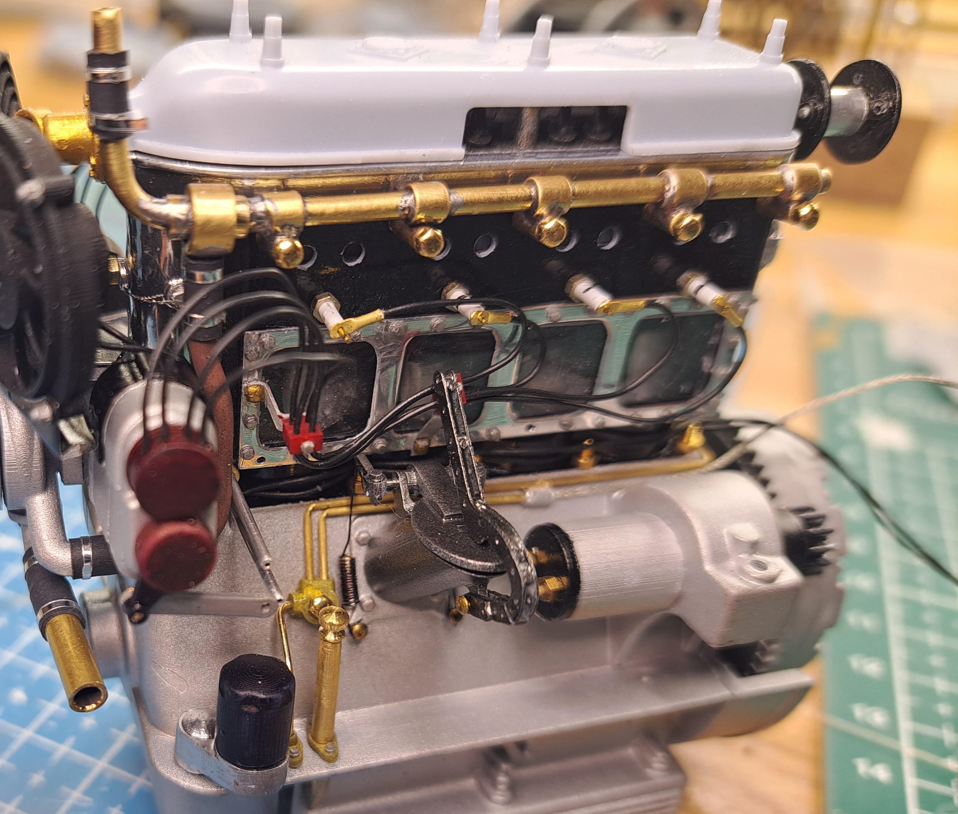
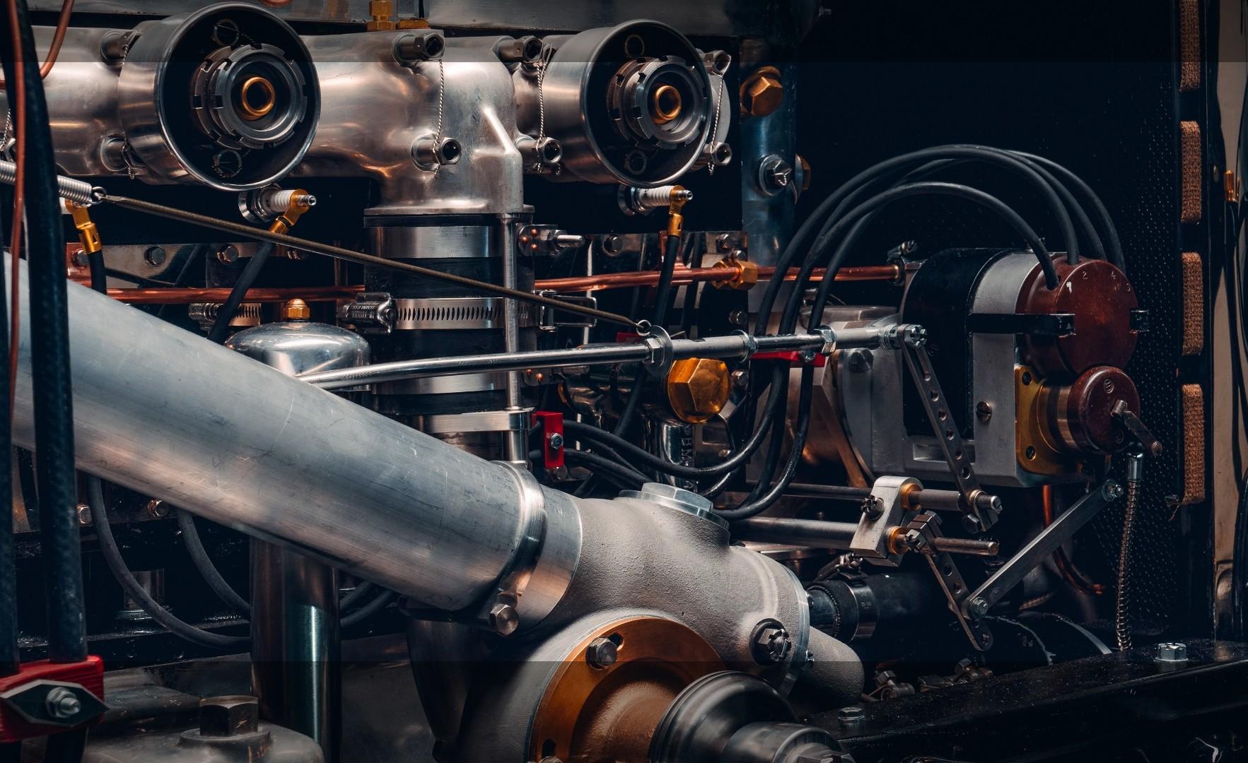
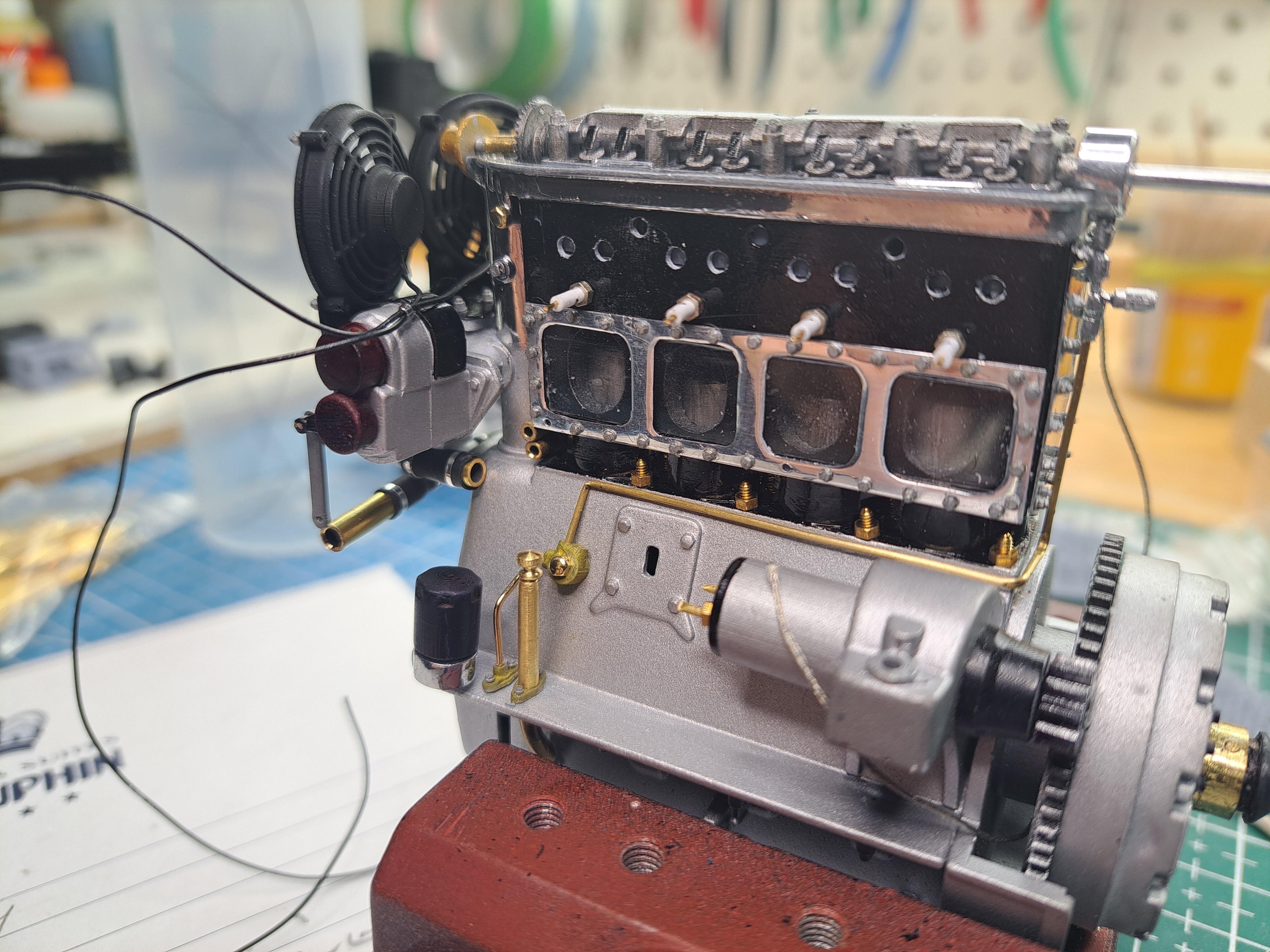
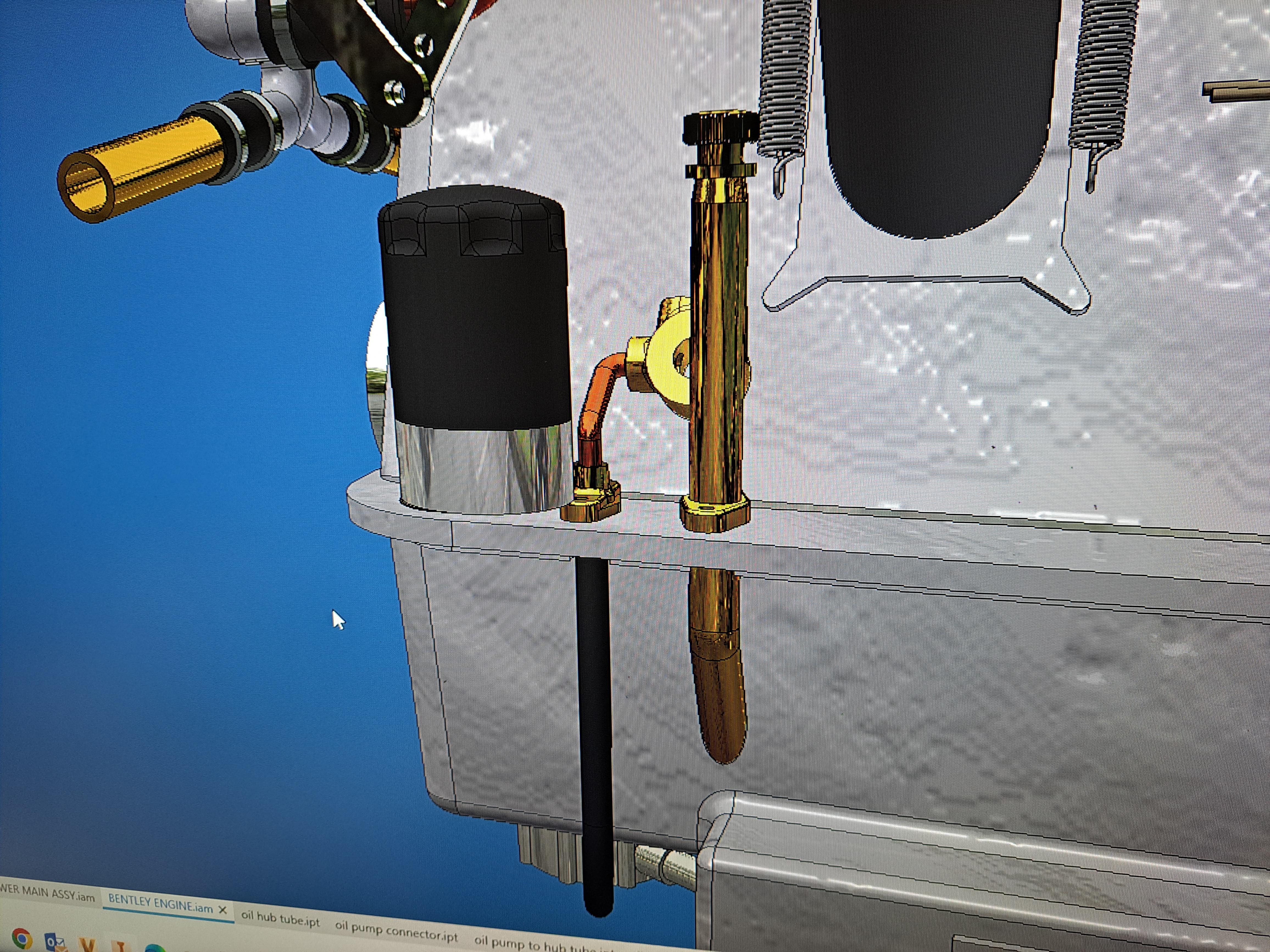
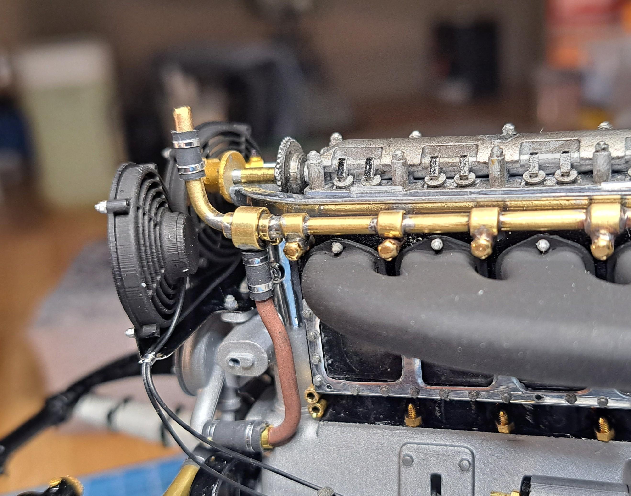
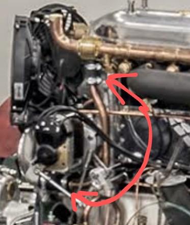
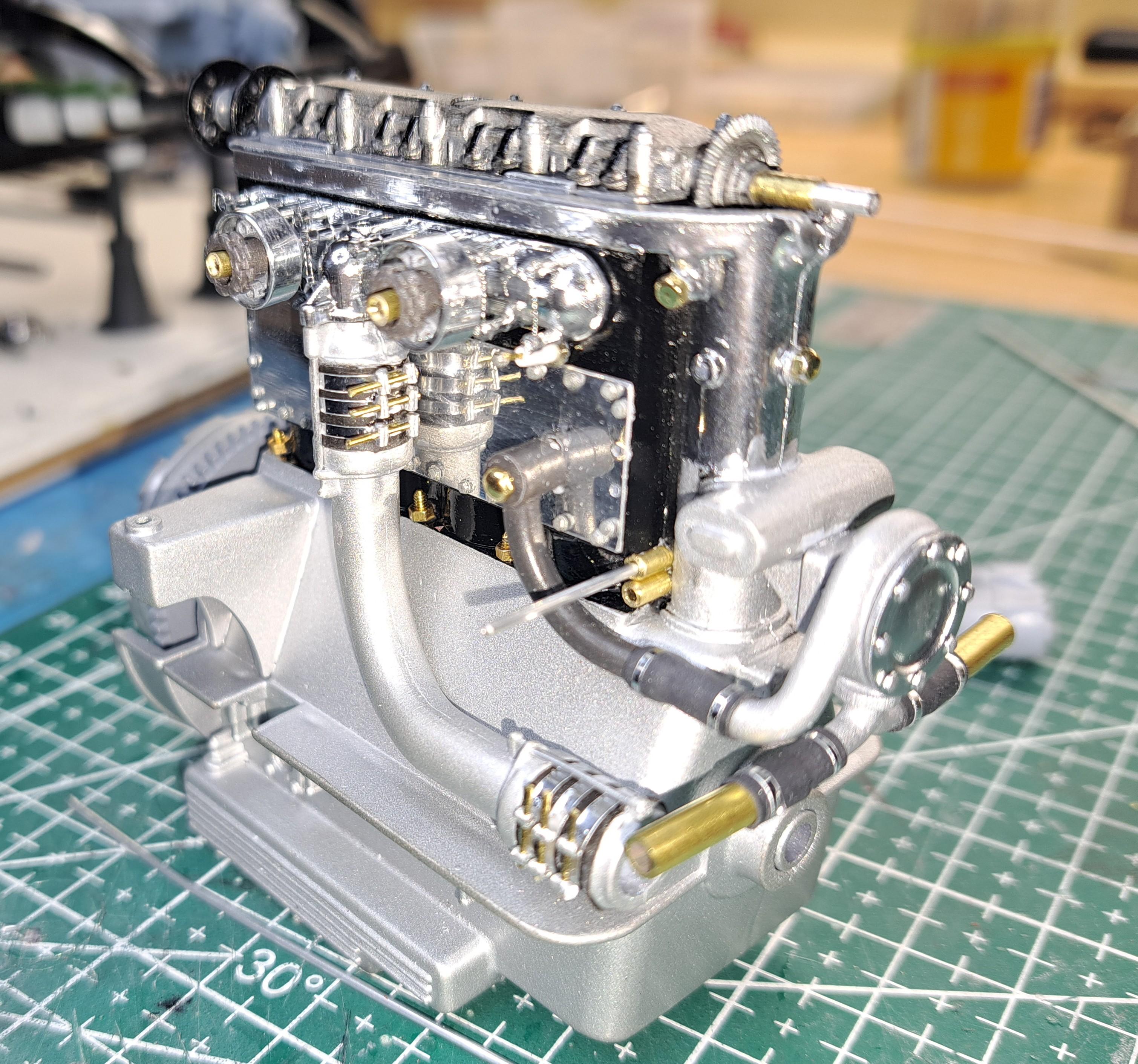
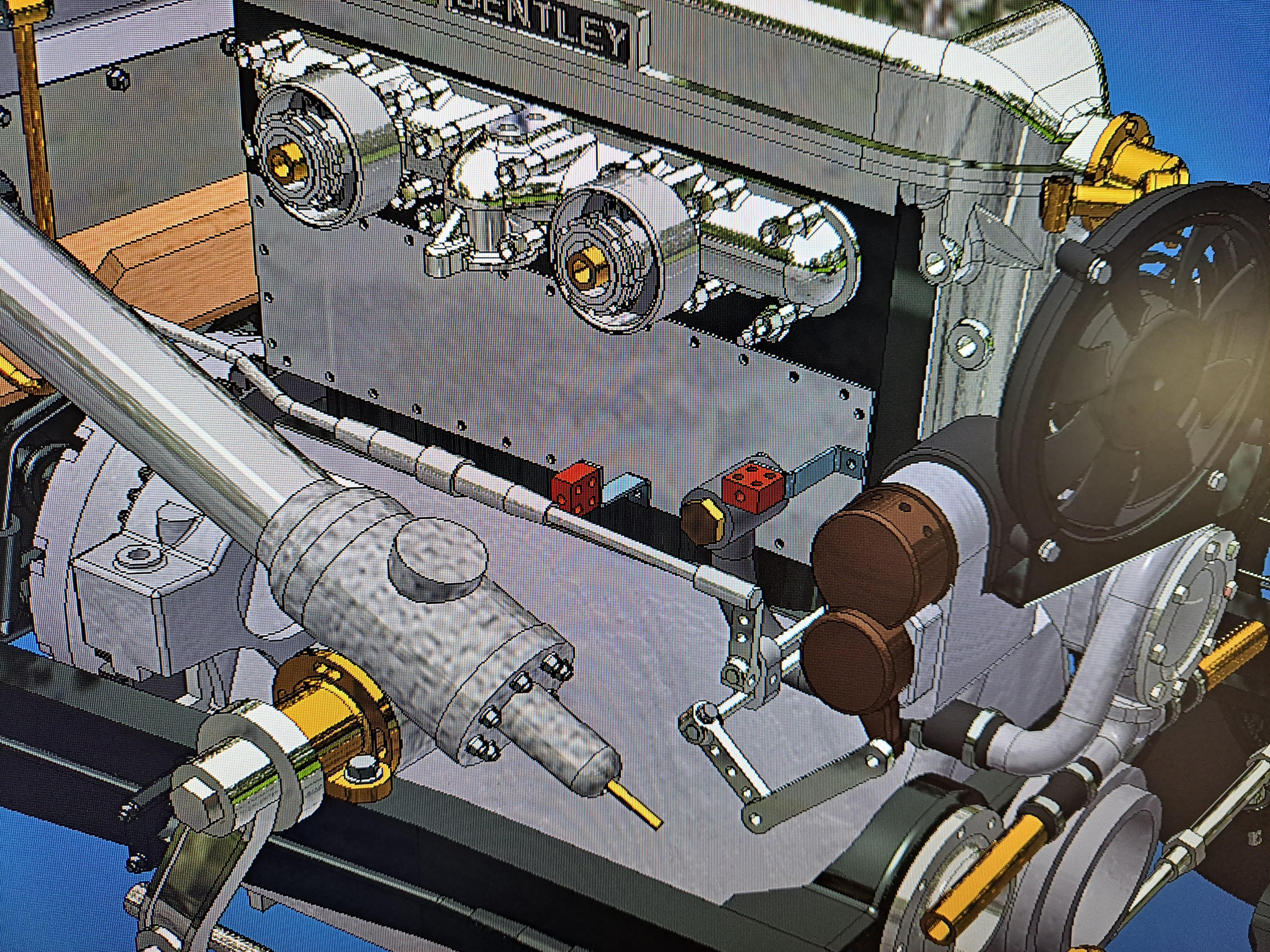
Received a bunch of printed parts for the engine. I test fitted the oil filler tube. Installed the oil filter along with a small connection hub and oil line to cam shaft. made 4 spark plug cable pass thru bloc Installed plug cables and magneto on drivers side. the real thing
-
Thanks peteski, Soudure, soudage...soldering, welding...ahhhh, l'm getting a headache!
-
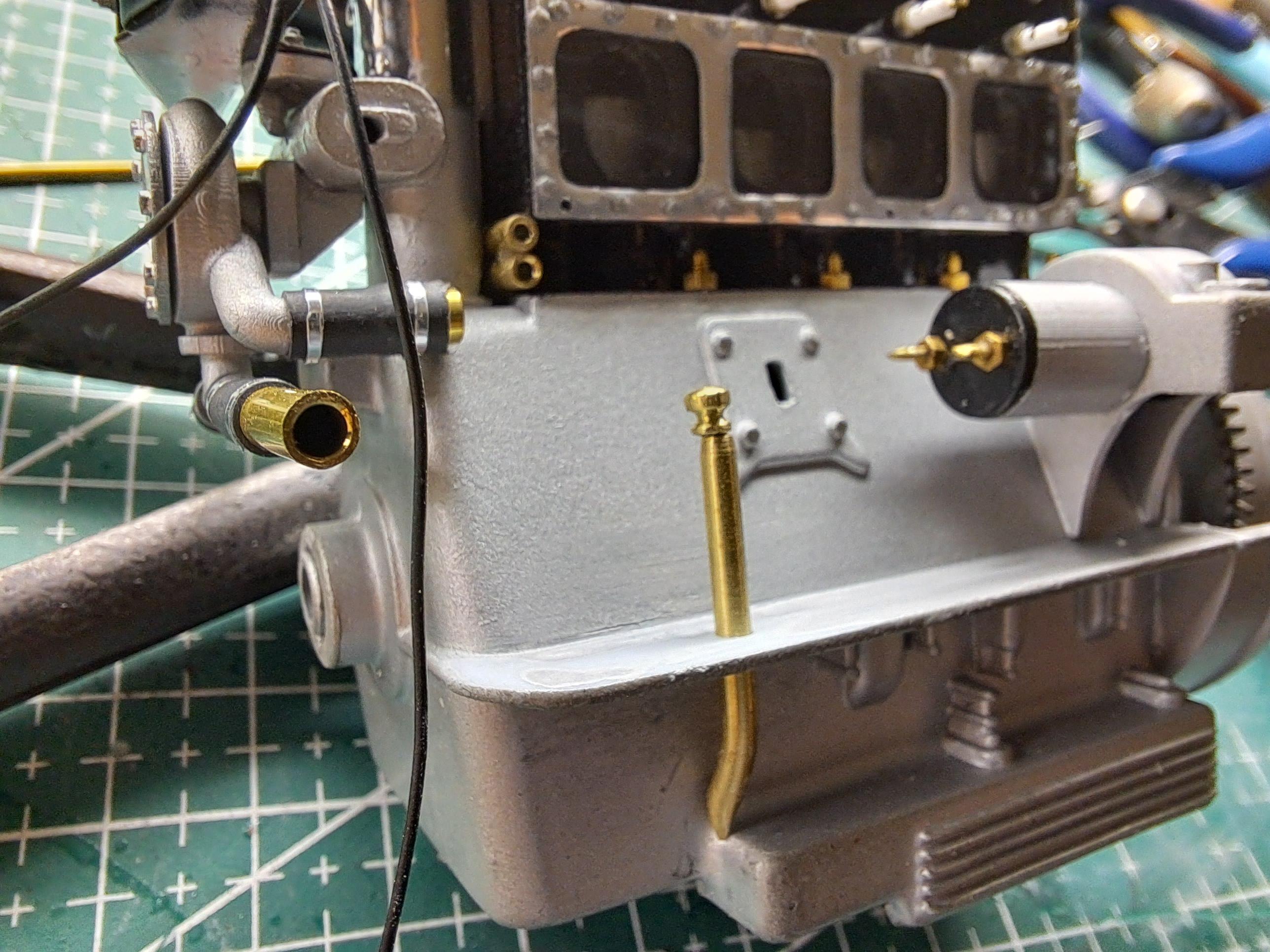
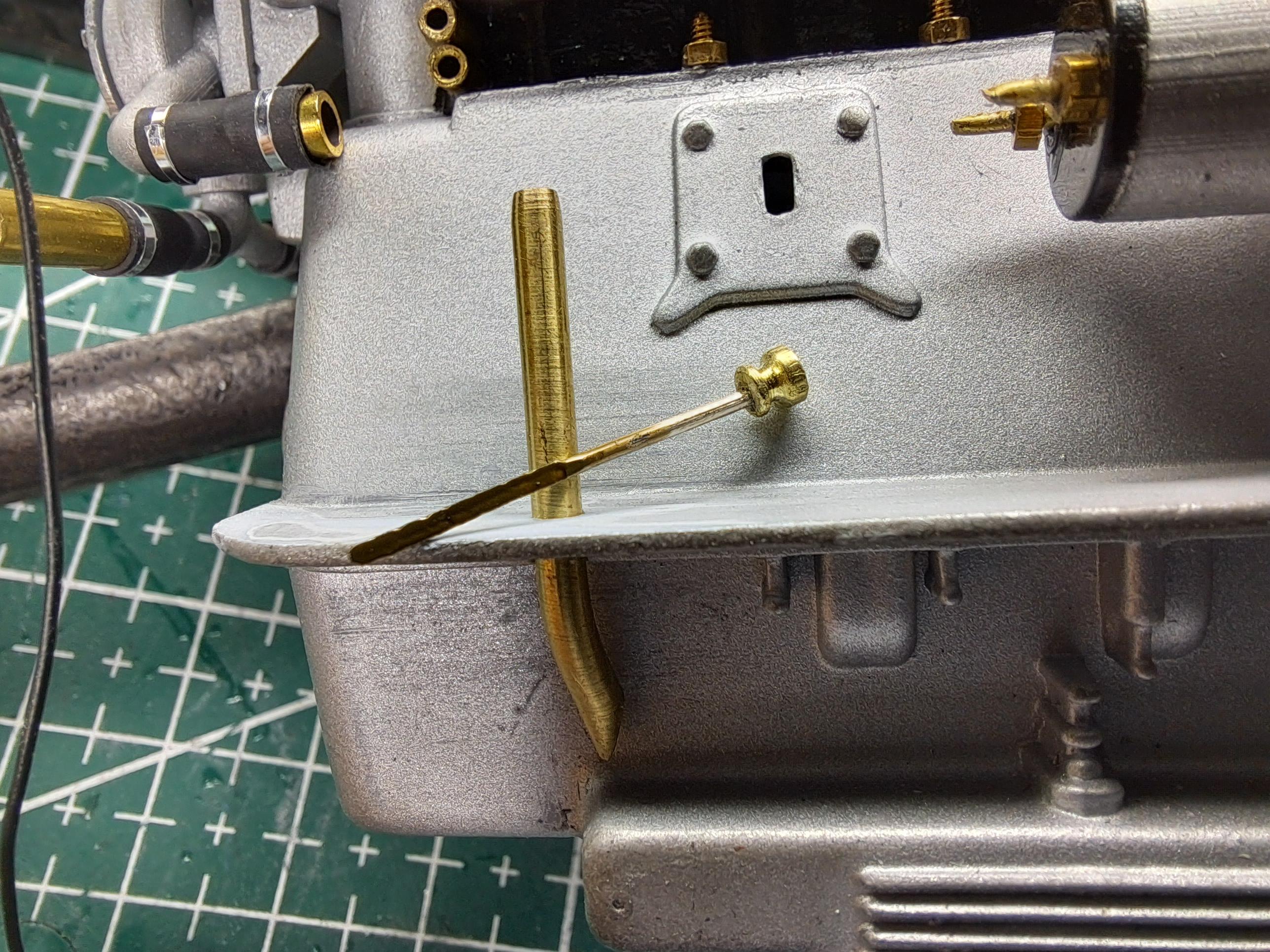
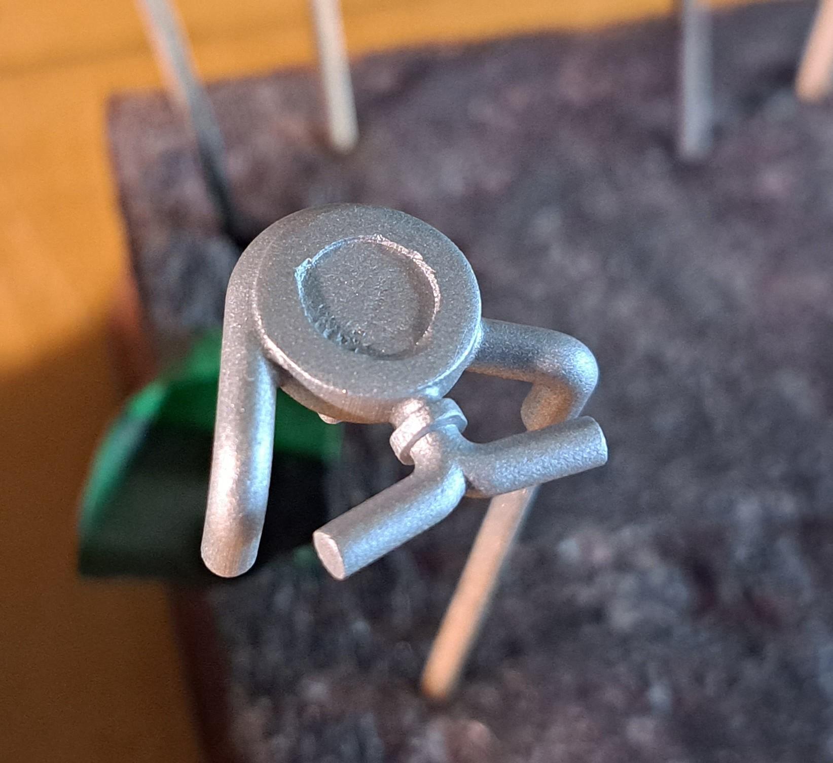
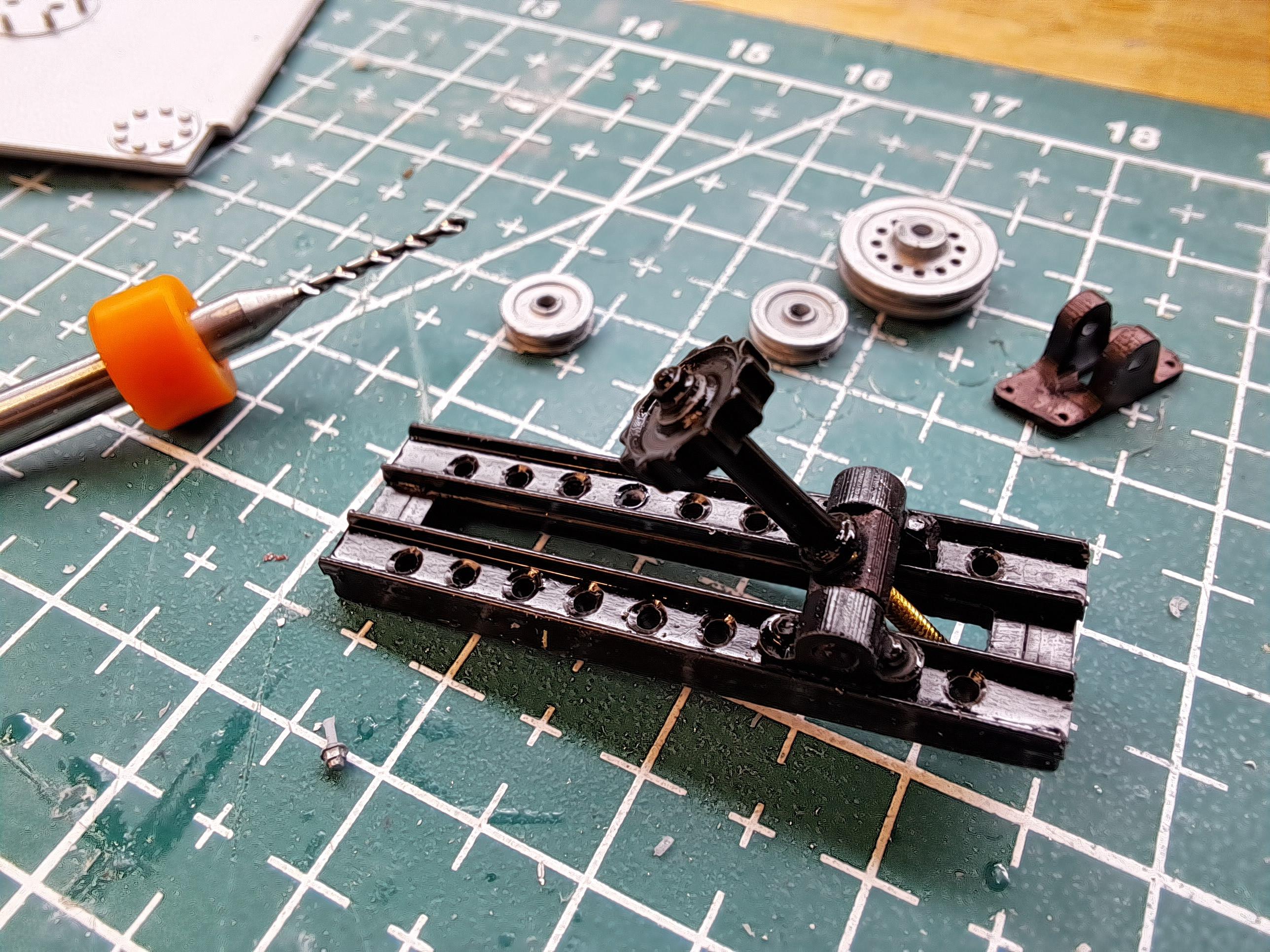
I did the accelarator. It's a welded brass assembly. The pivot incorporate a compression spring as on the real thing. I also started the link rod that goes from the pedal to the carb lever along with the springloaded return rod that goes with it. Here's what the real thing looks like. and my version Since I'm waiting for a bunch of resin printed parts, I decided to do a bit of ground work on the wheels. First, I drilled the rims using the drill jigs I designed and printed last summer. They worked great. Then I printed a lasing jig to hold the rim and hub in relation during lasing. And did a bit of test lasing to get the feel of it. It should turn out all right. Drill jig in use Lasing jig lasing jig in use test fit on car
-
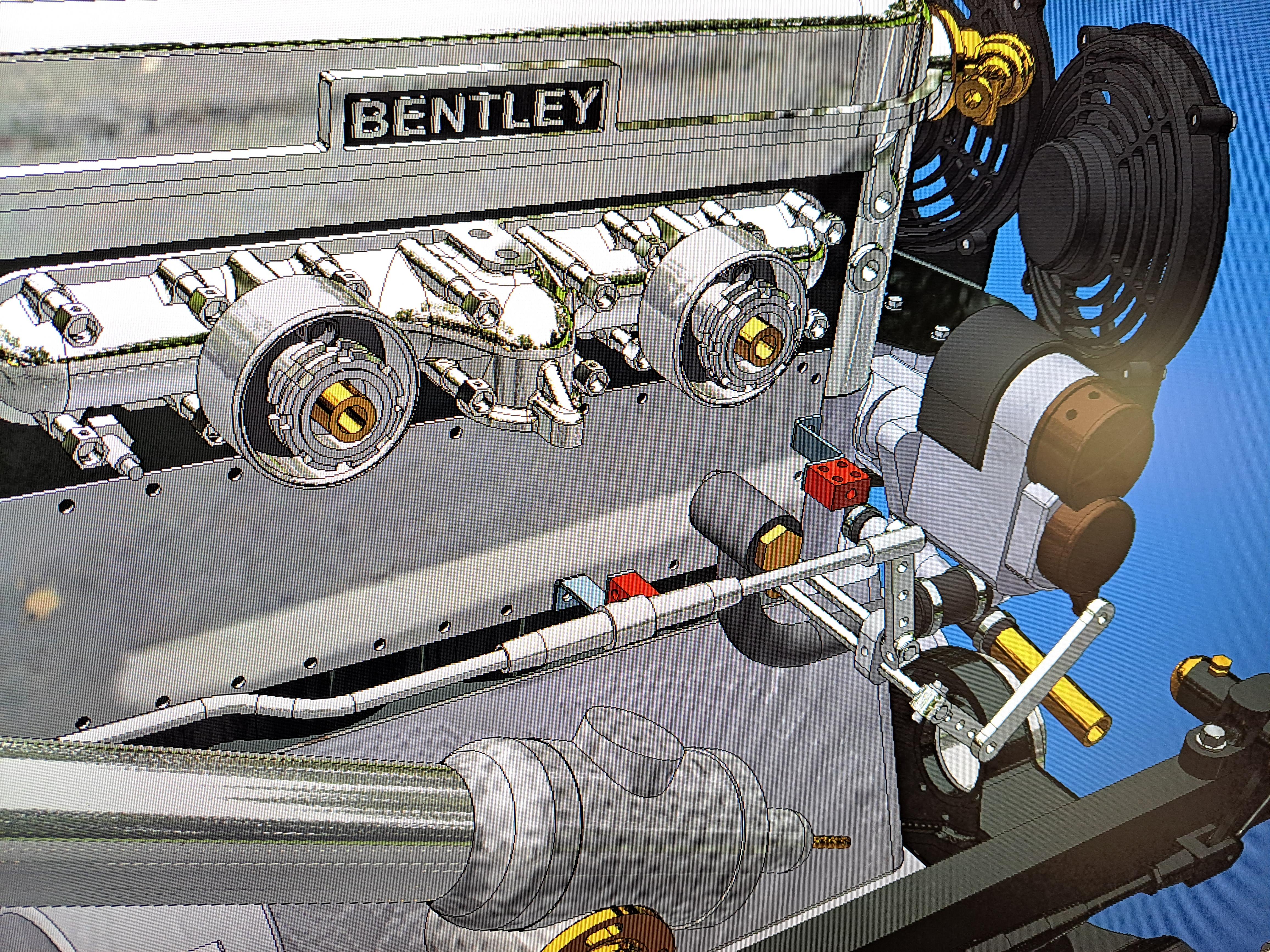
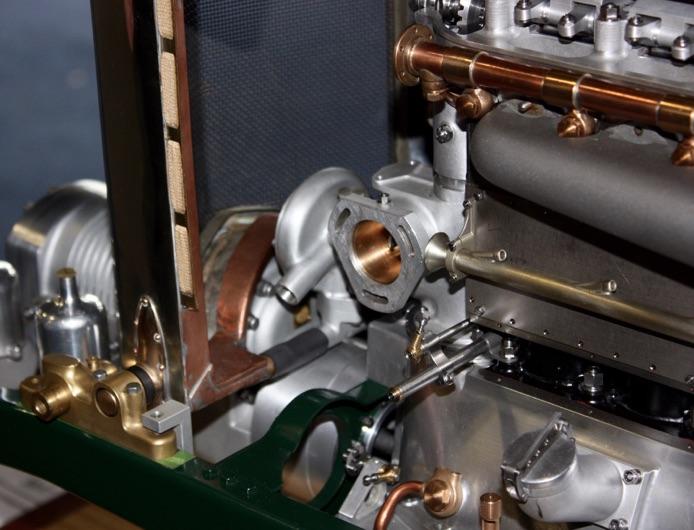
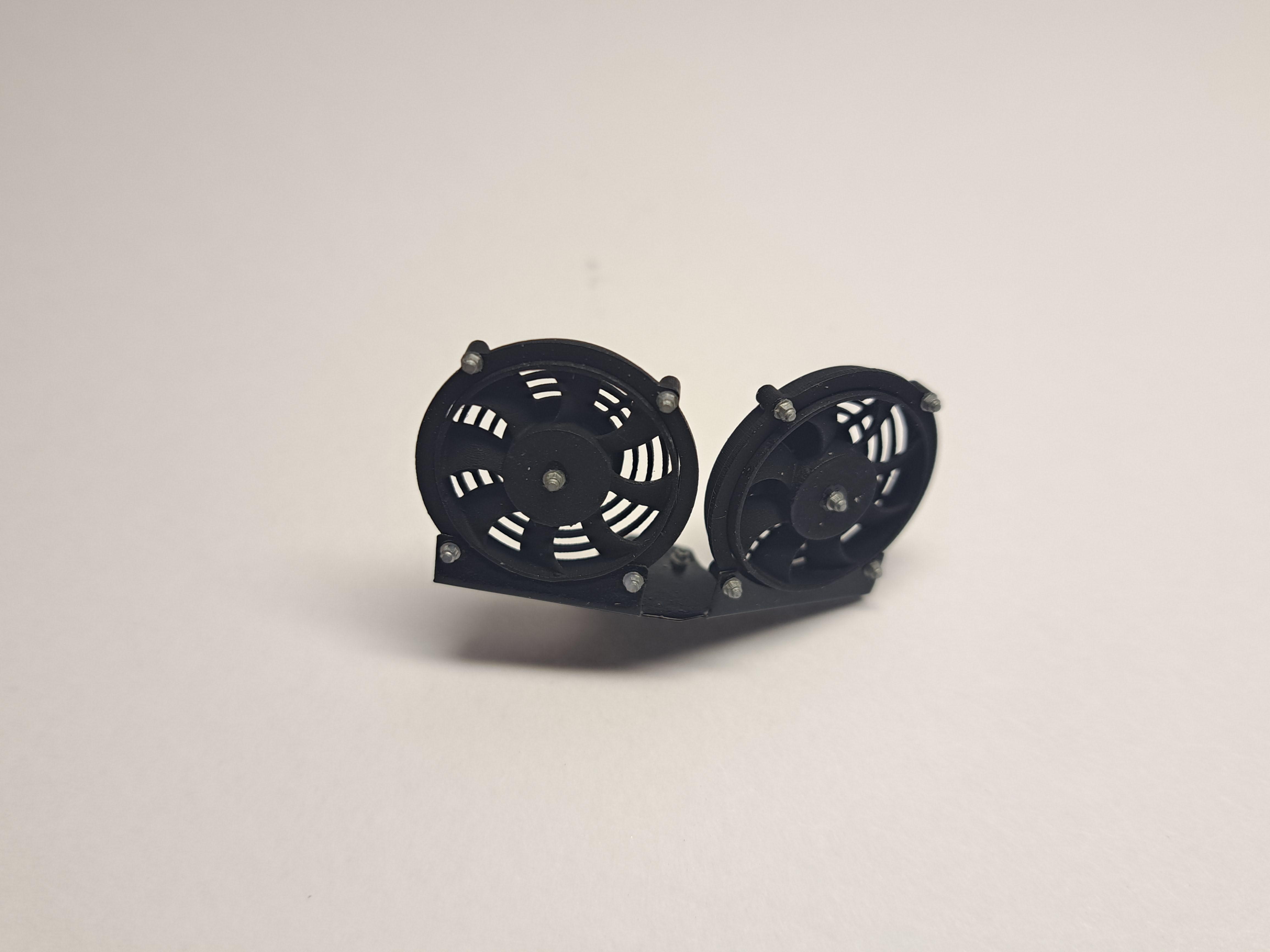
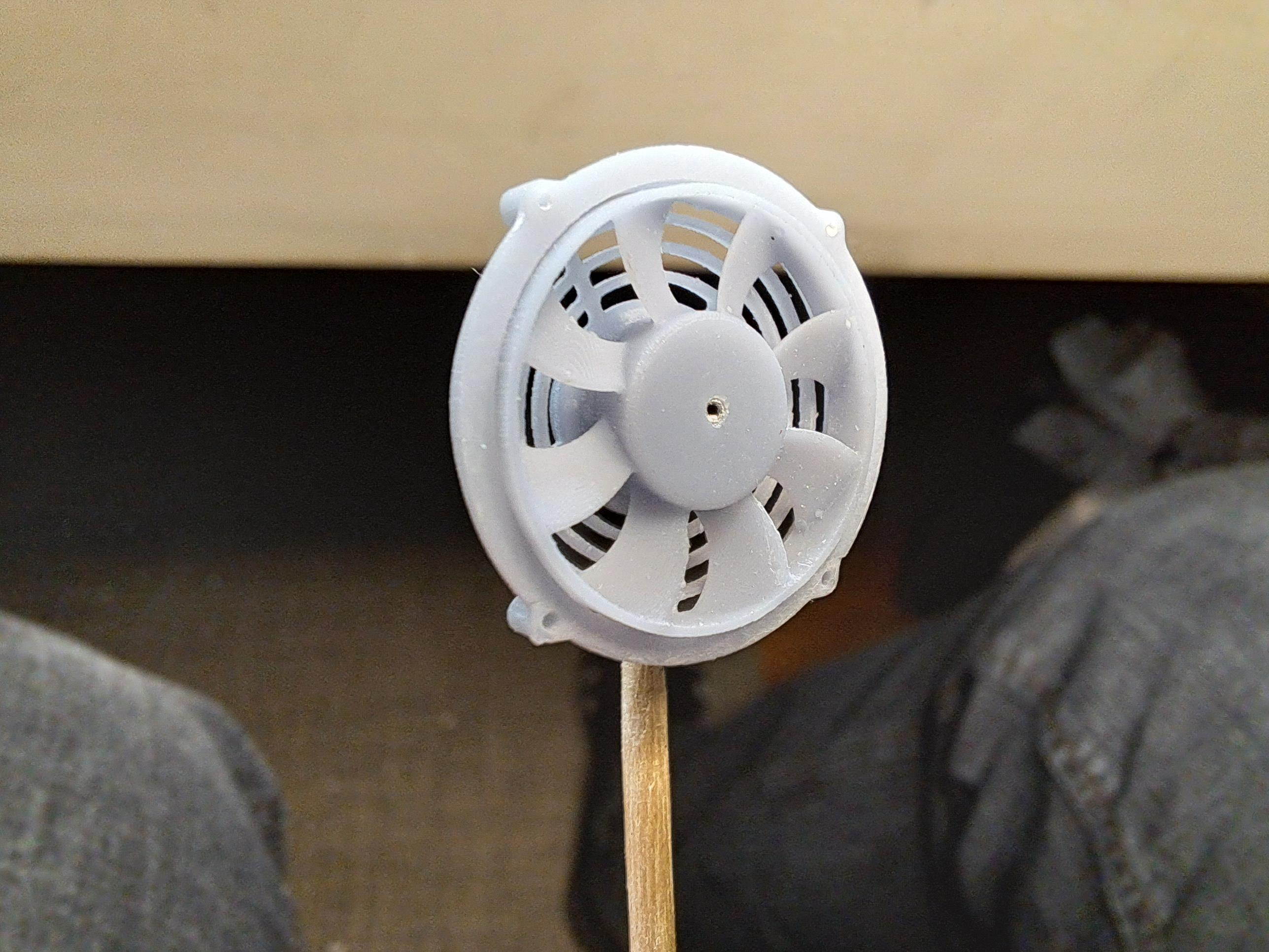
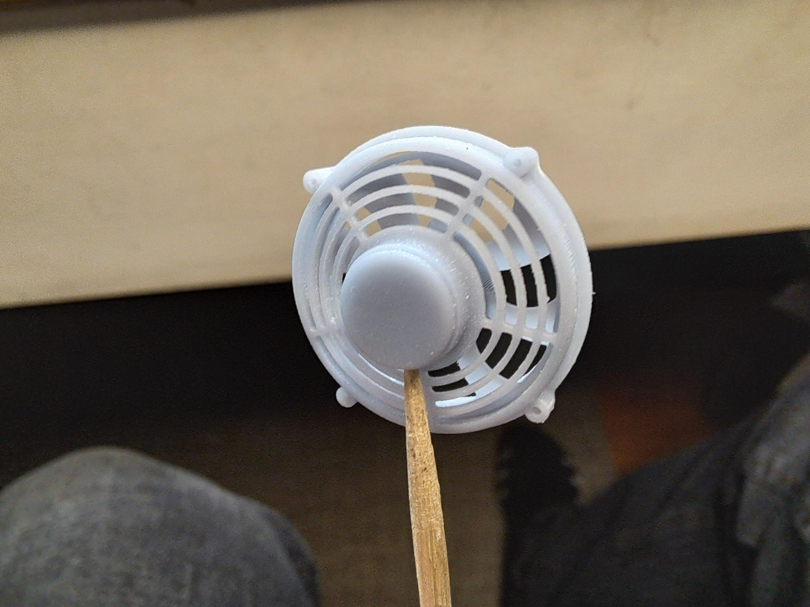
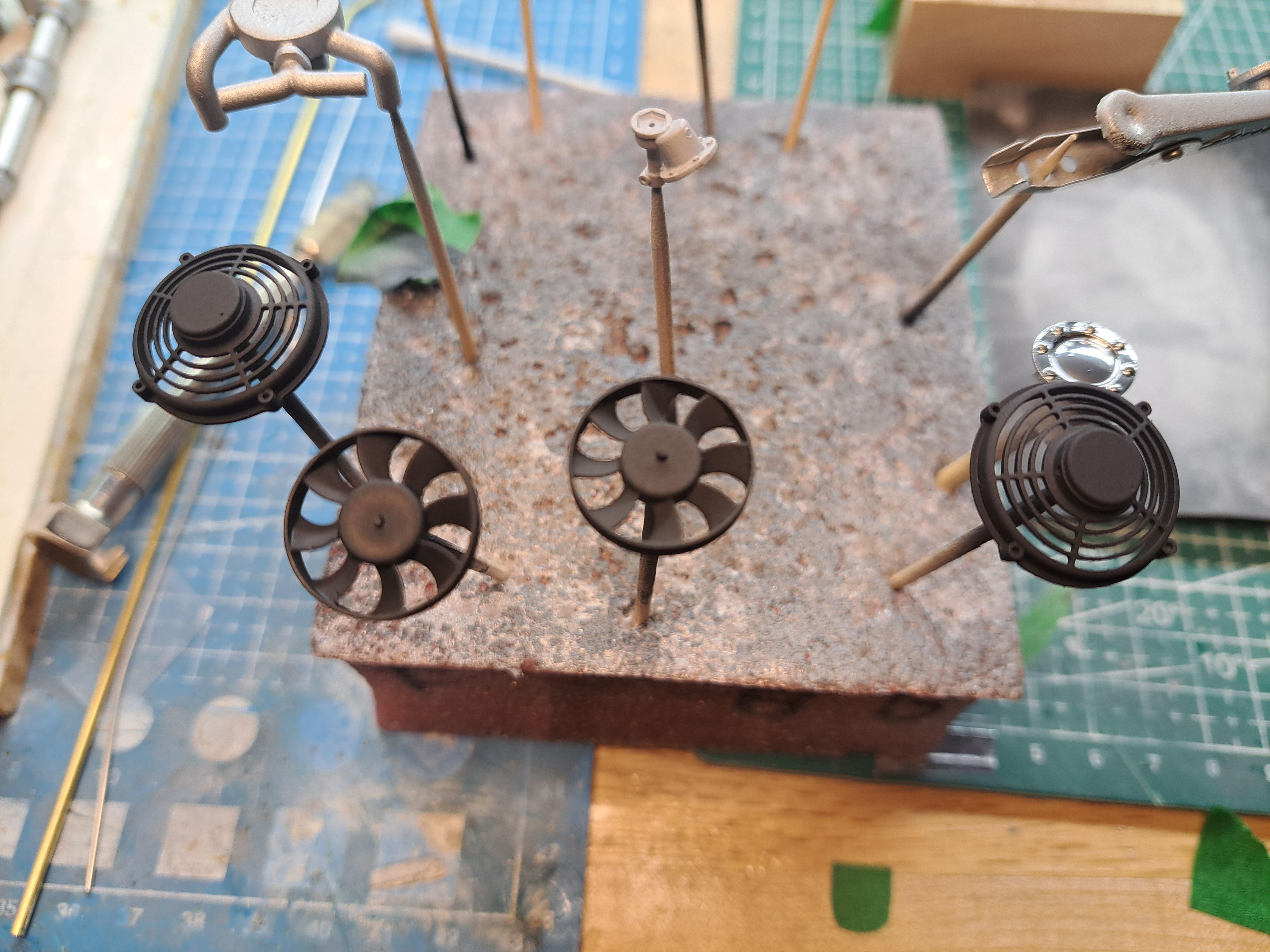
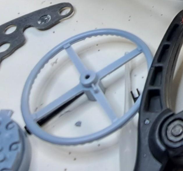
Pierre, most of the original parts are used althougt most are modified to some degree. Pretty much all printed or fabricated parts where not in the base kit and are add-ons. I've been working on the oil management system which is not present in the base kit. Aside from a hose on the underside of the engine, that seems to go from the oil pump to the sump, there's nothing. I had already made the oil level dip stick but I didn't like it so i made a new one. I'll also add a modern type oil filter, the oil pump, an oil distribution hub that will connect to the cam shaft among other things. The one part that is in the kit, the hose under the engine, will be modified by replacing the plastic hose by a real rubber hose plus I'll add another hose from the pump hub to the distribution hub. I also added the cooling fans. Here are a few pictures. Only part present in kit New dip stick Oil on stick 3d modeled components to be added Cooling fans in place 20231102_114231.mp4
-
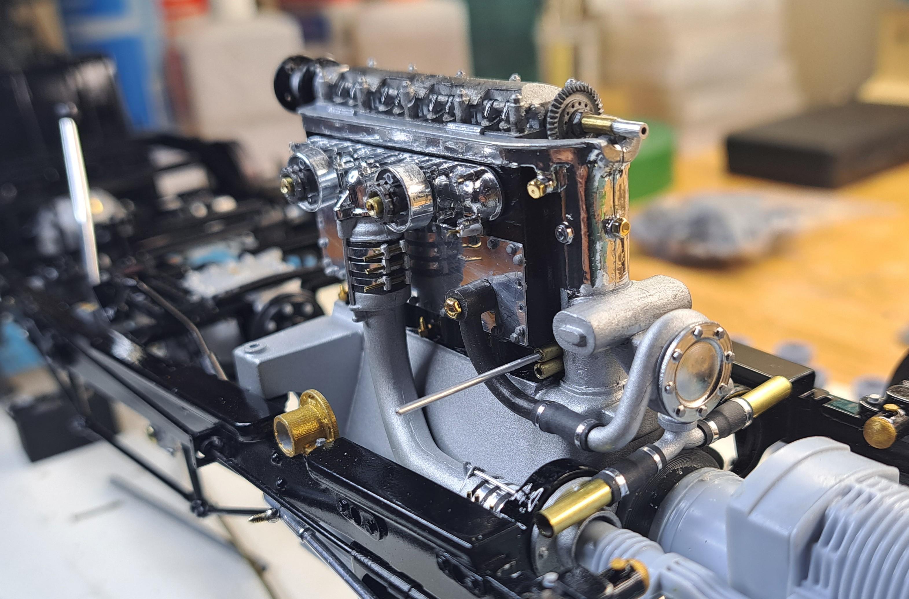
I discovered that on the new old bentley blowers built in 2019, there's a pipe connected to the water rail going down to the water pump. Back in the 30's, this pipe was used only on the non blown car, not on the blowers. Here's the pipe on one of the 12 new Blowers. So I added it to the rail setup. I also added the tubing that will connect to the top of the radiator. I also added the starter motor which is actually a micro gearmotor.
-
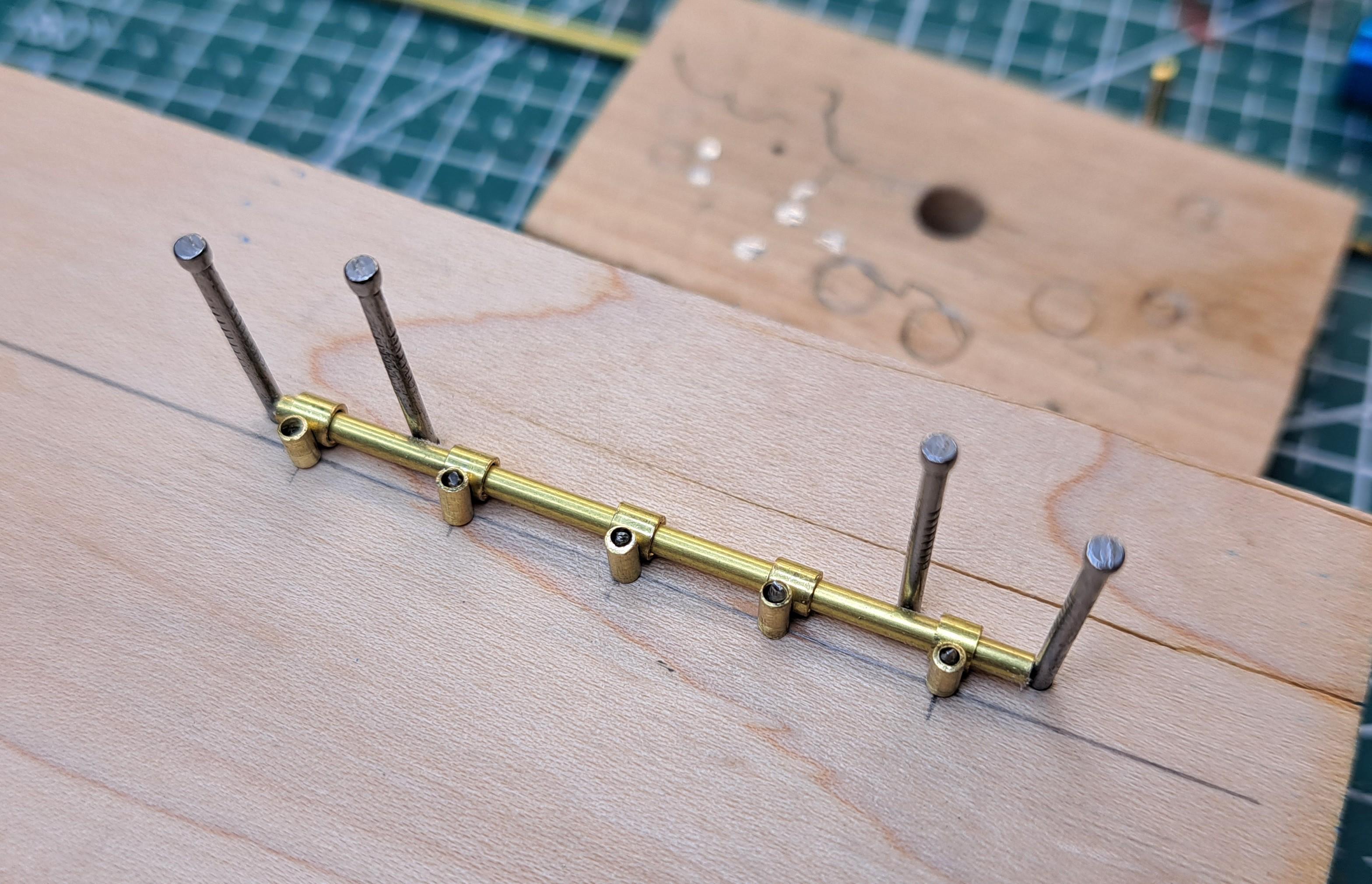
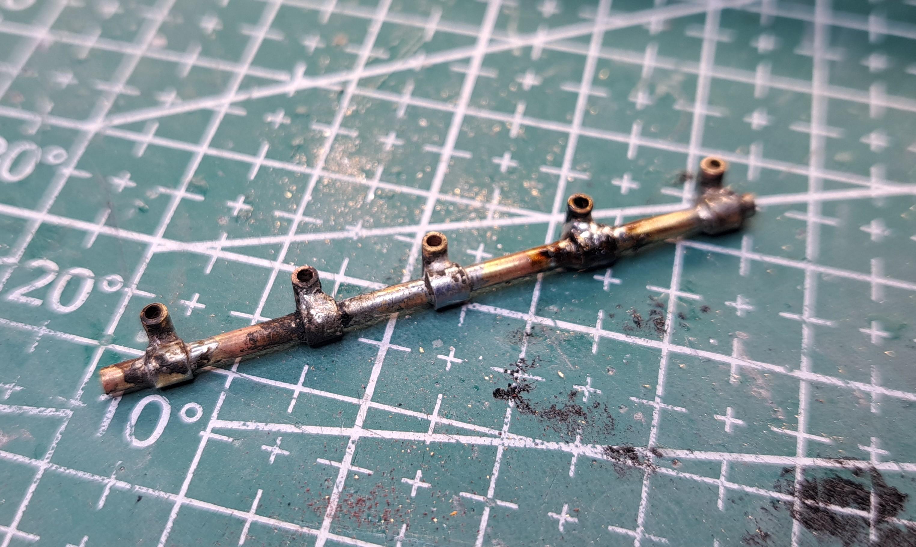
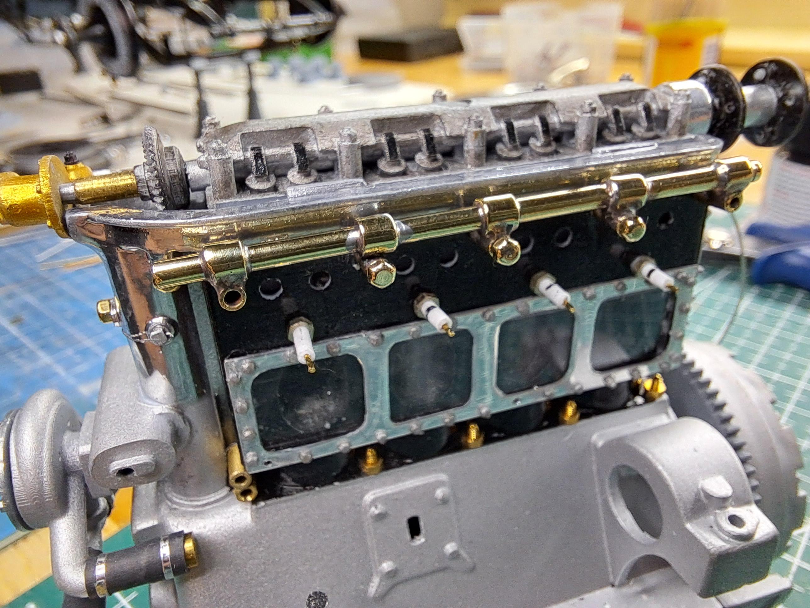
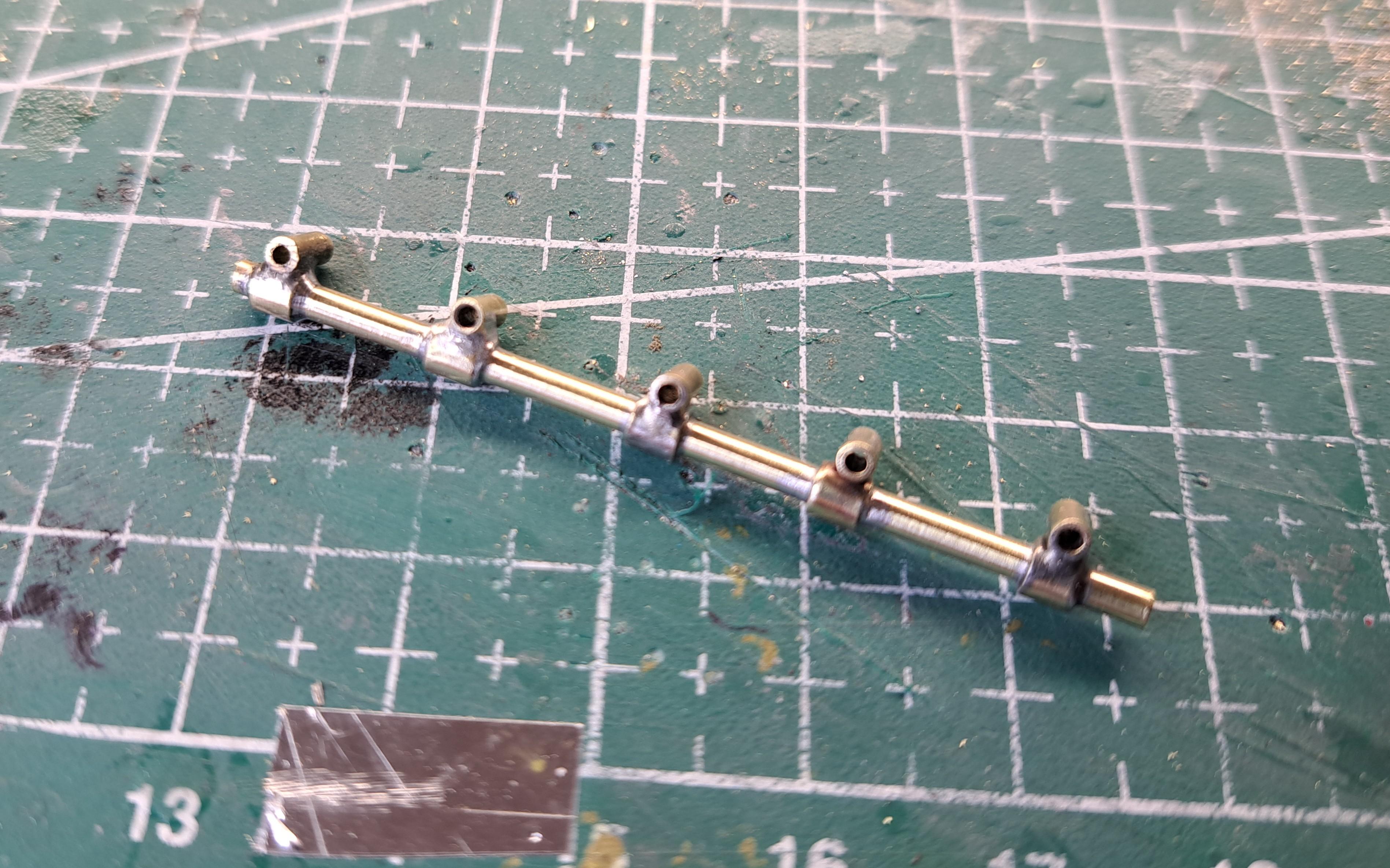
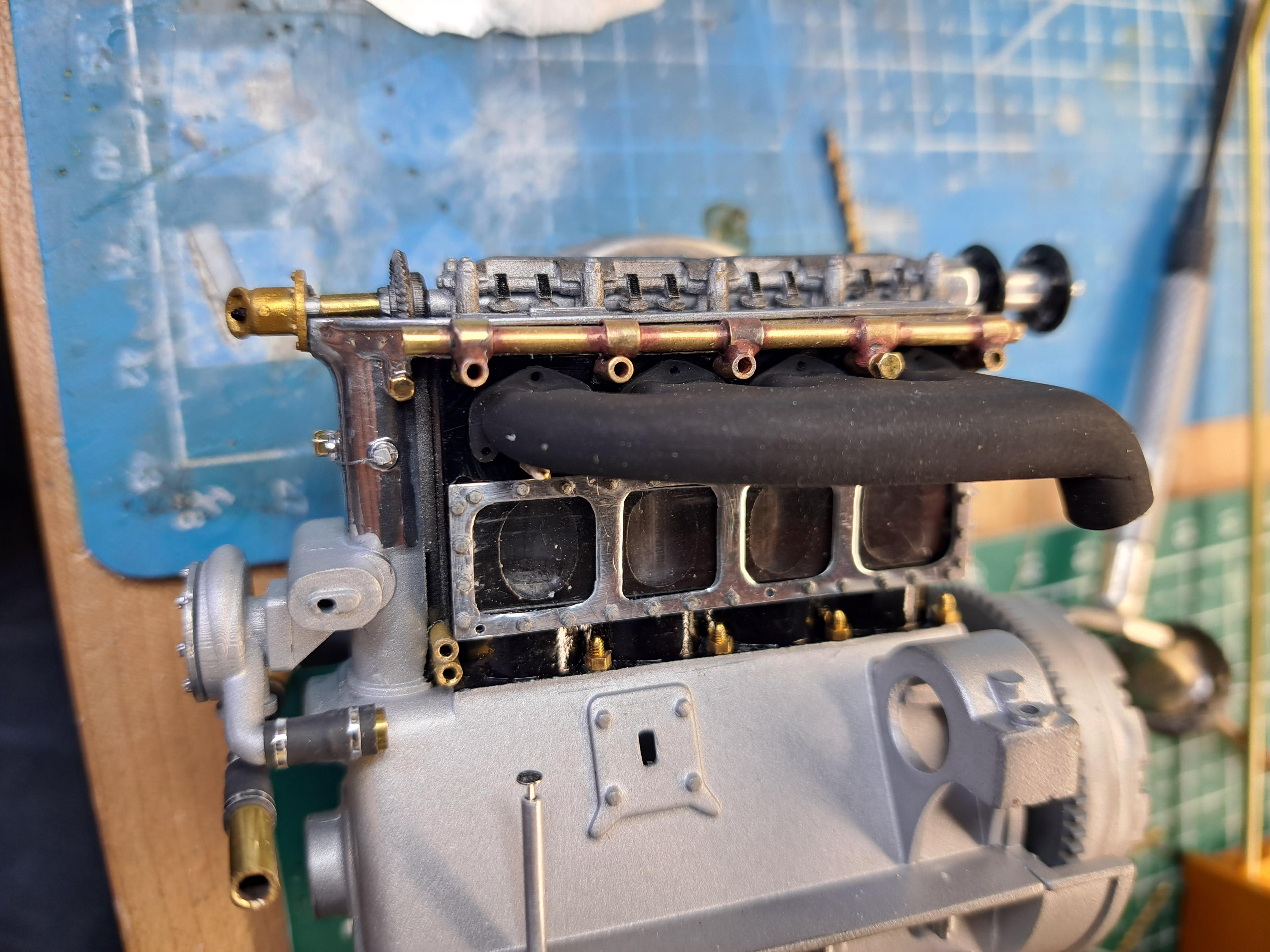
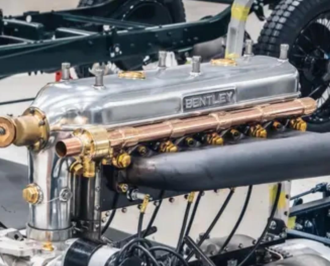
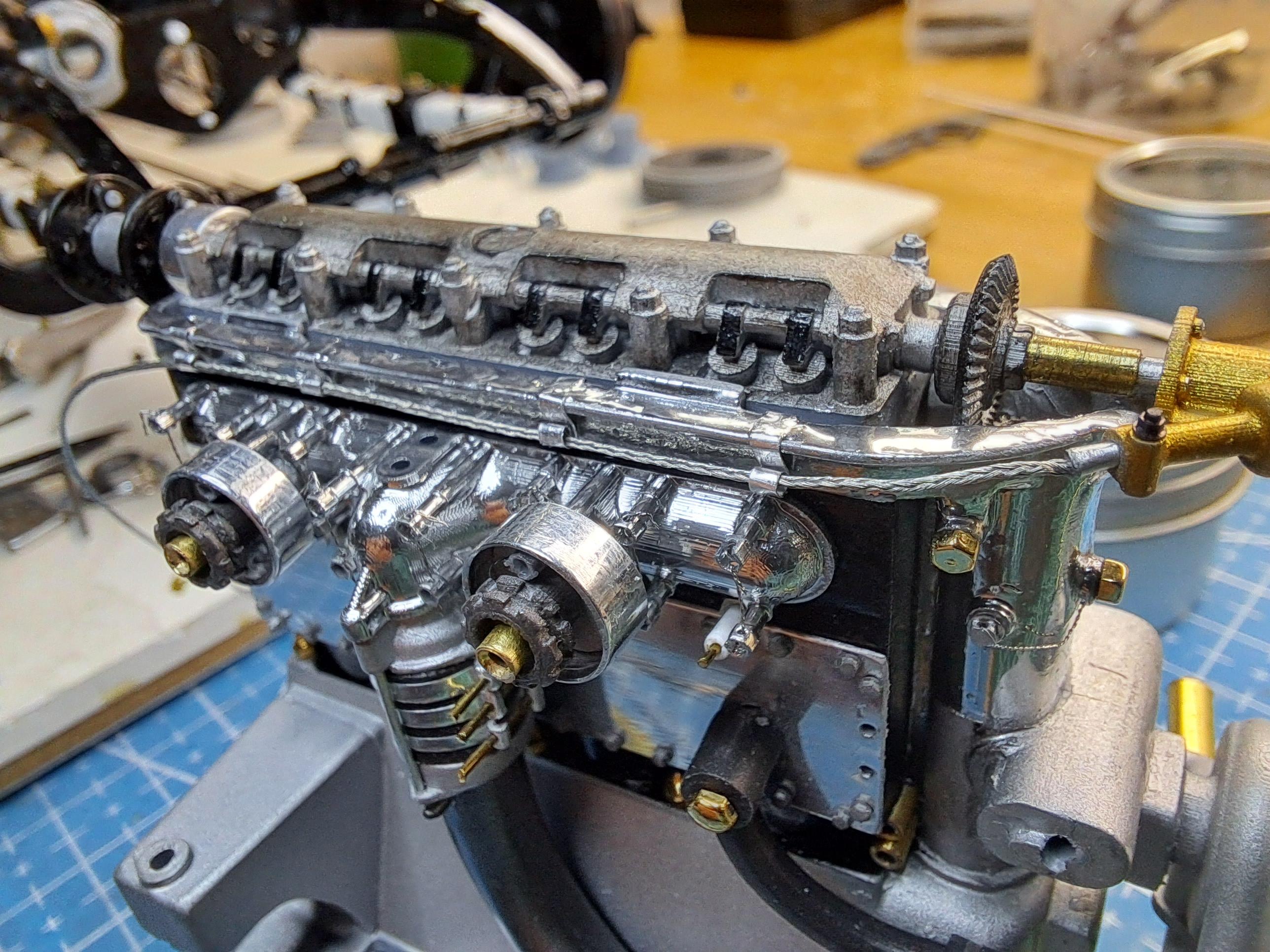
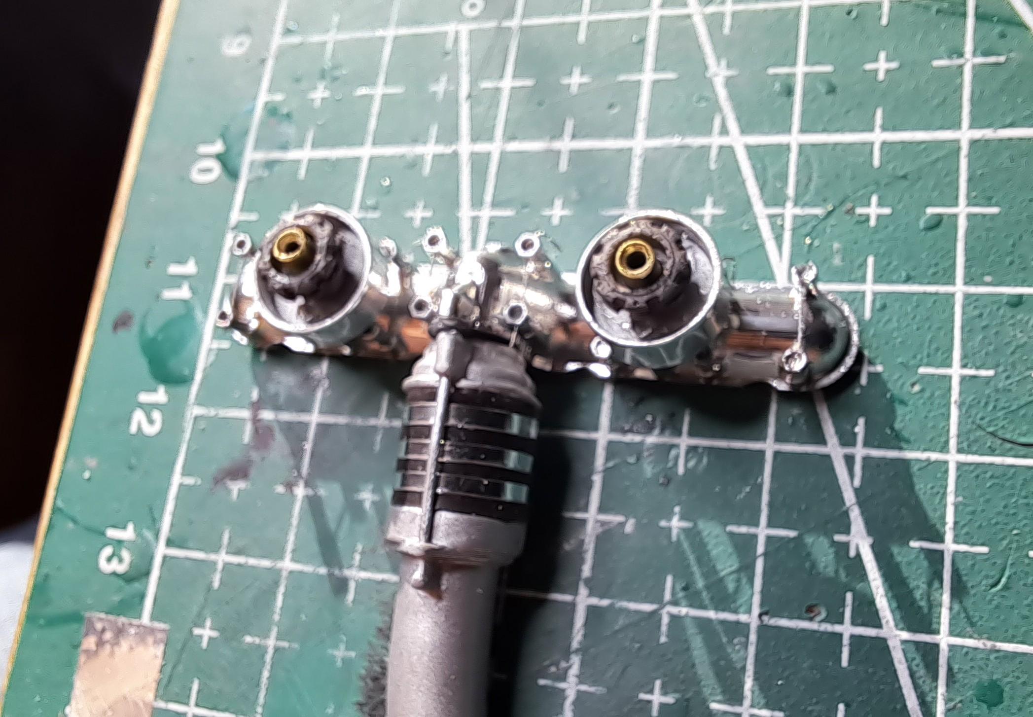
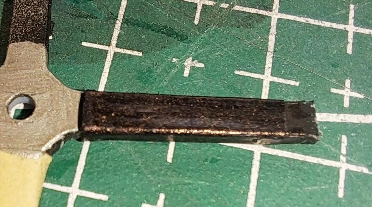
I fabricated the water rail but instead of using a piece of soldering lead colored copper, I used brass tubing, both for the main tube and for the jonction couplings. After cutting all the parts, 11 in all, I tried to glue them together. That did work so good. I decided to solder the joints as on the real thing. So I started by making a welding jig. Which is this. On my first try, I used small steel pins to hold the 5 small vertical tubings but after soldering, the pin were stuck inside the tubes. So that didn't work either. This was the result. I then replaced the small steel pins with aluminium pin and applied much less solder. This is what came out of the jig. much better. And after cleaning i got this Test fitting to make sure it would fit with the exhaust manifold and after a quick polishing, got this. I'm very happy with the result, it came out a lot better than expected. Now I just need to go get a few hex bolt (I'm missing 1 at each end) and to figure out how to make the jonction to the rad.
-
Continued on a few more engine details today. Did the oil level indicator. Installed the rev counter with rev cable and tiny cable clamps I started to tinker with the water rail, it's this copper tubing. I would like to make it from scratch using a lenght of lead, colored with a copper patina acid and a brass tubing to represent the jonctions. Not sure if it will work but I'll give it a try.
-
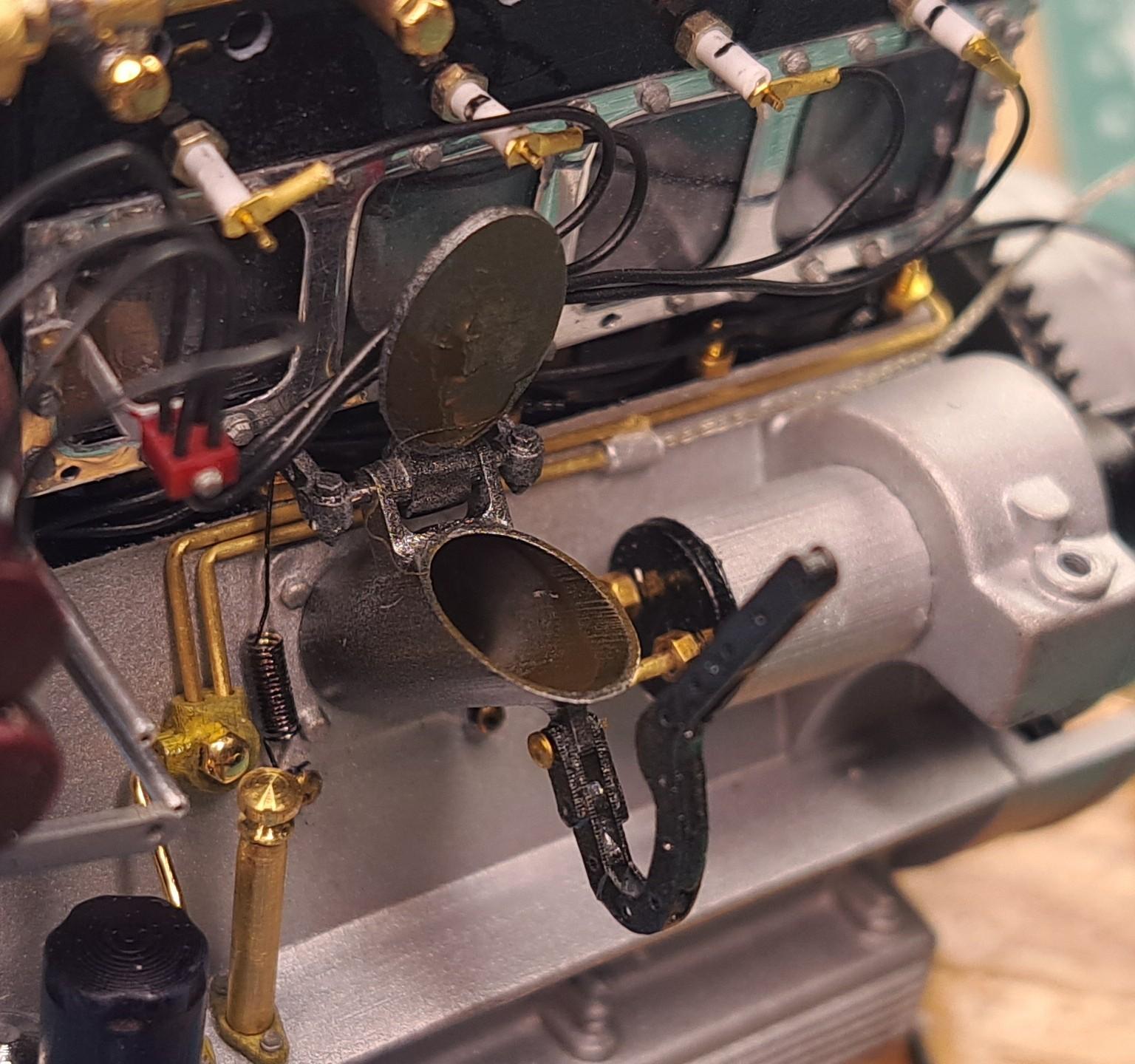
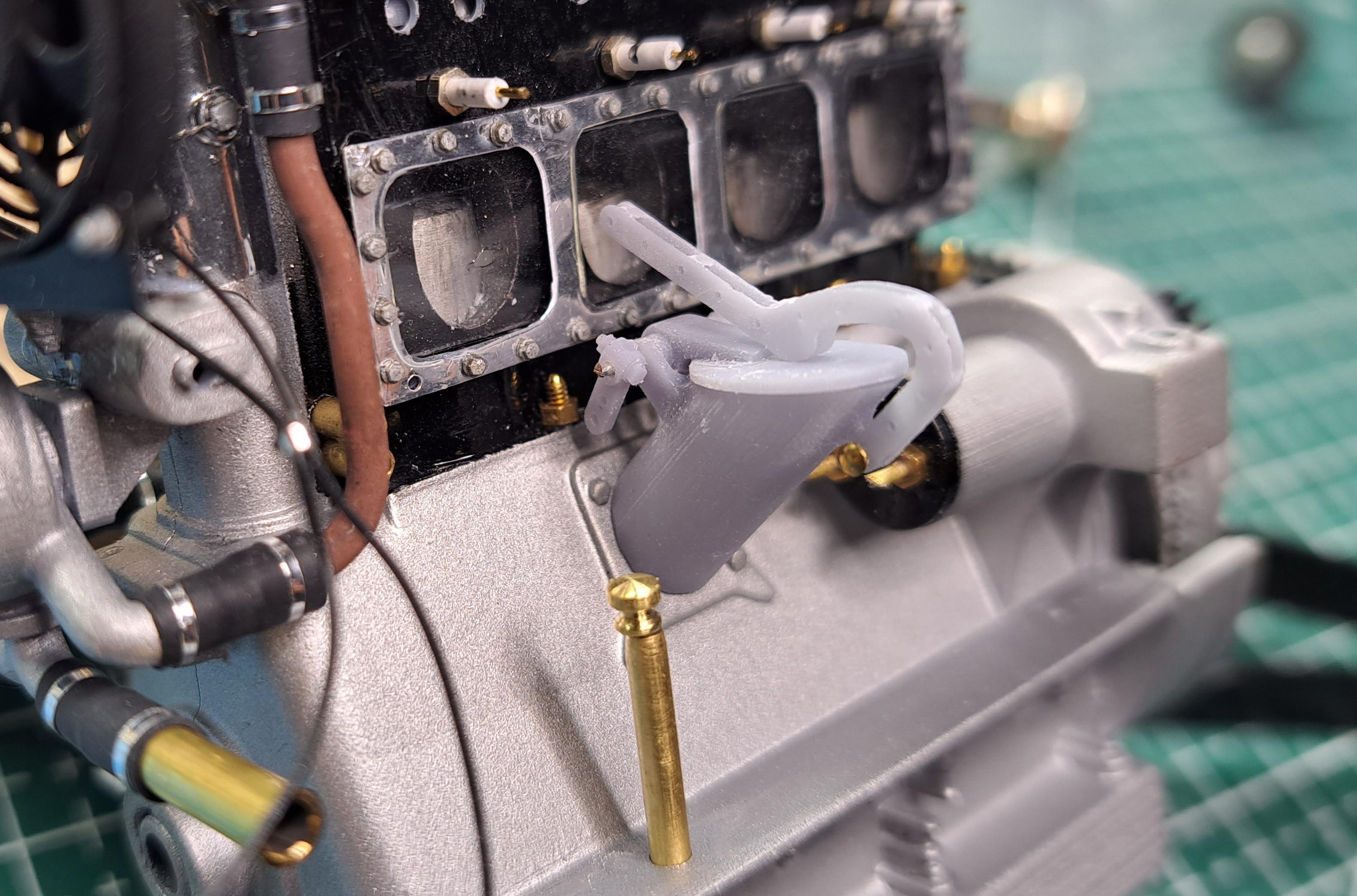
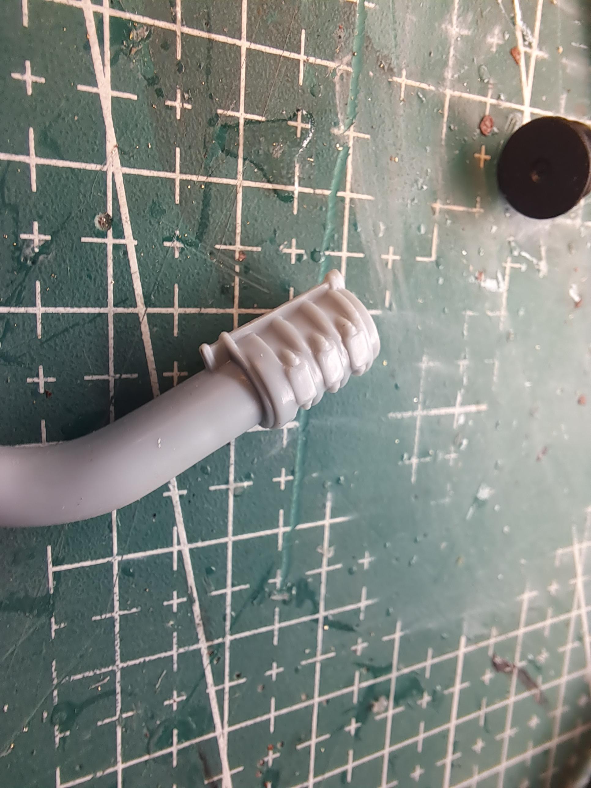
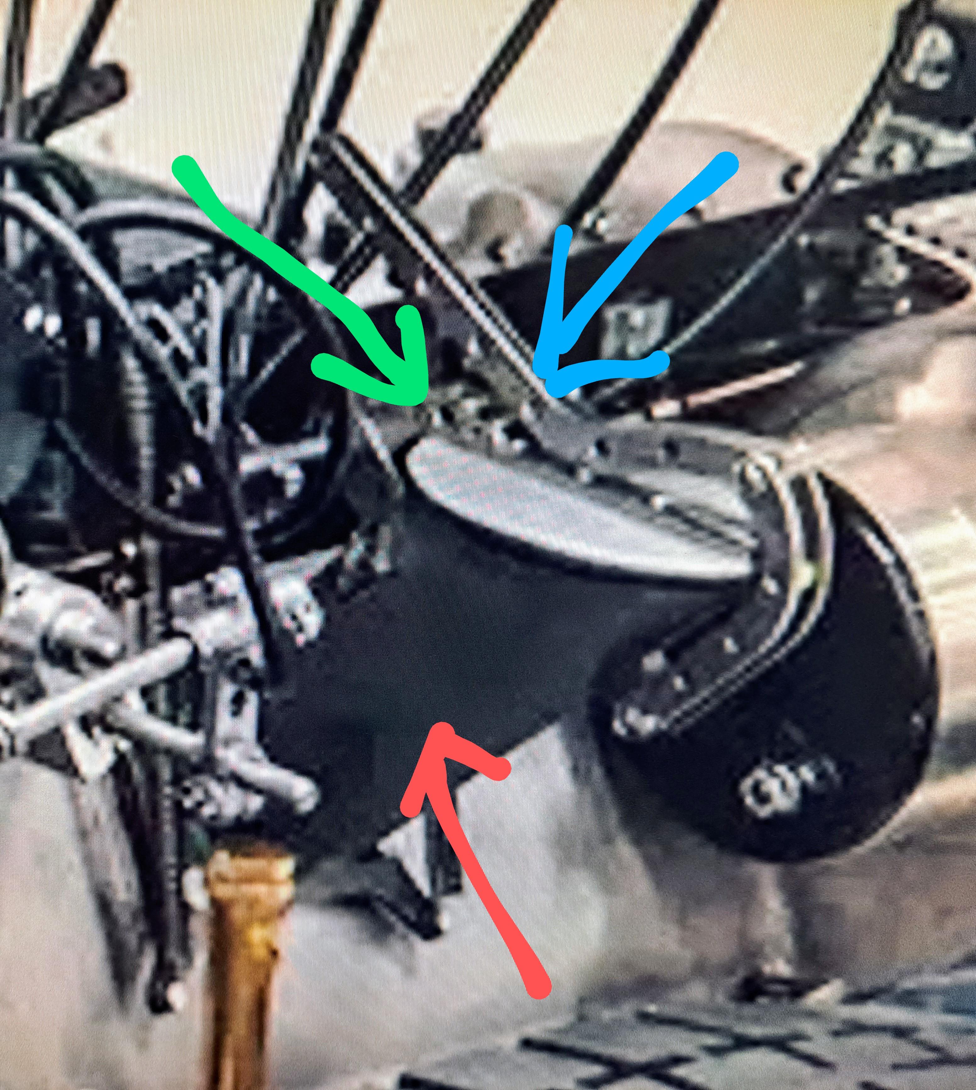
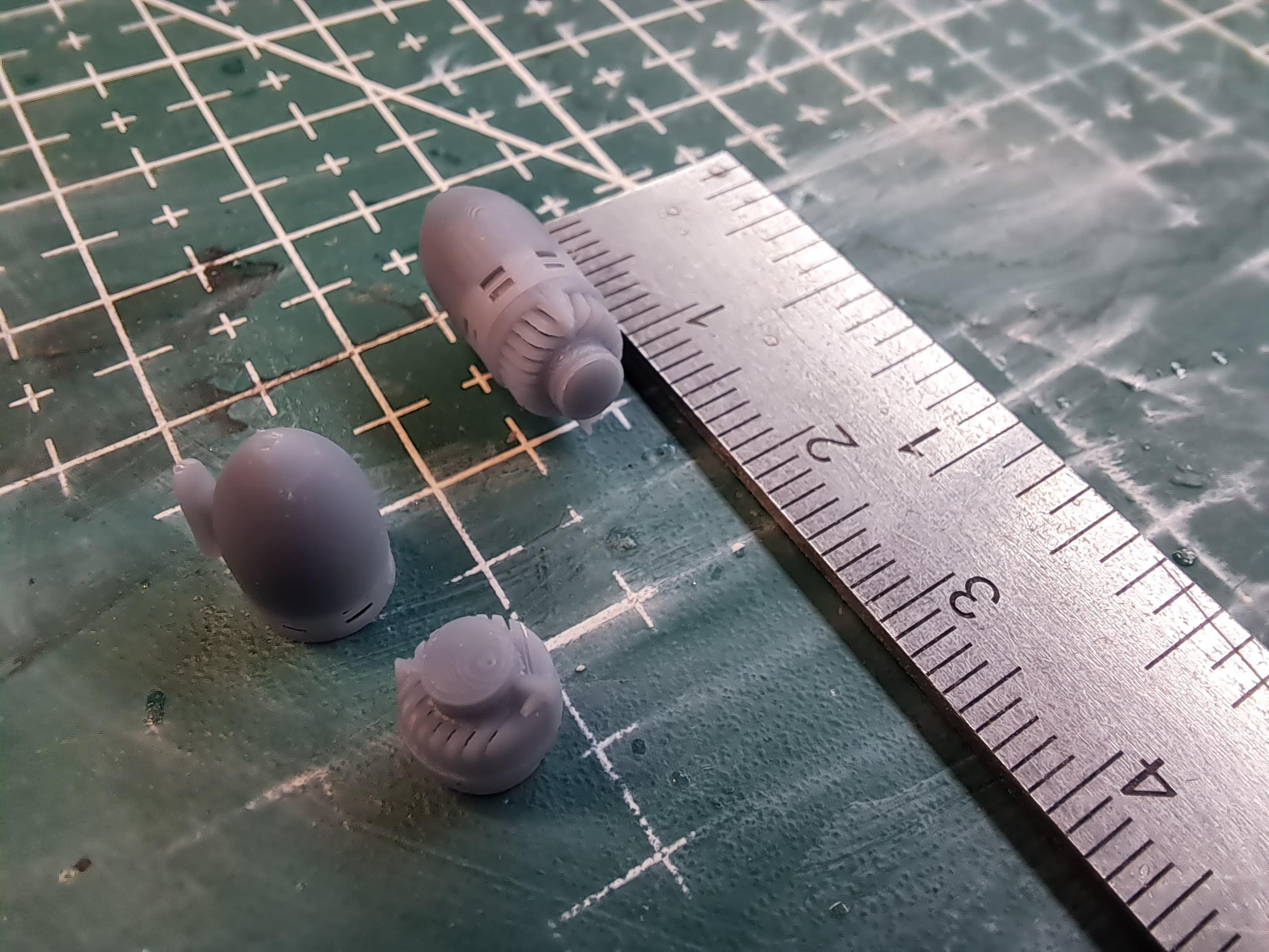
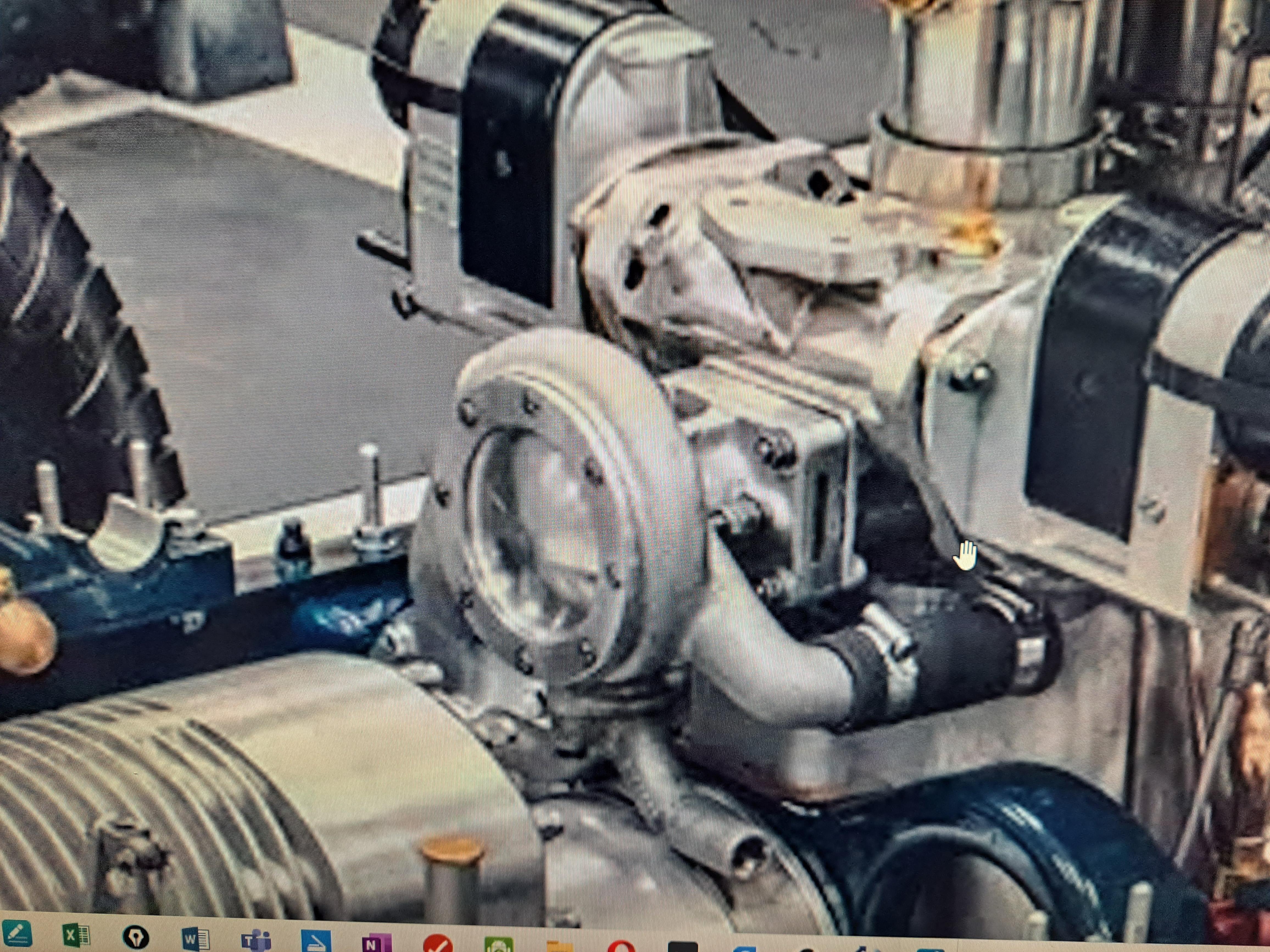
Worked on the blower feed tube today. I removed the moulded features at both ends of the part. These moulded features represent a rubber coupling with 3 hose clamps and tie rods. This is the real thing. And here is mine without the clamps And once finished Next. I tackled what seems to be the oil filler neck. it's this thing. Pointed in red is the filler tube, in blue the cap release lever and in green the cap pivot assy which has a pivot shaft and 2 levers connected to extension springs. I 3d modeled it the best I could considering the bad picture and lack of info I have. This is what I have. 20231028_195245.mp4 I'll print the cap and levers, the rest I'll either modify or build from scratch. I also finished modeling the magneto linkage.
-
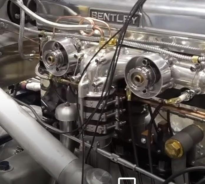
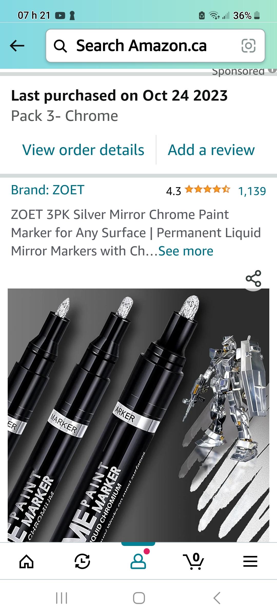
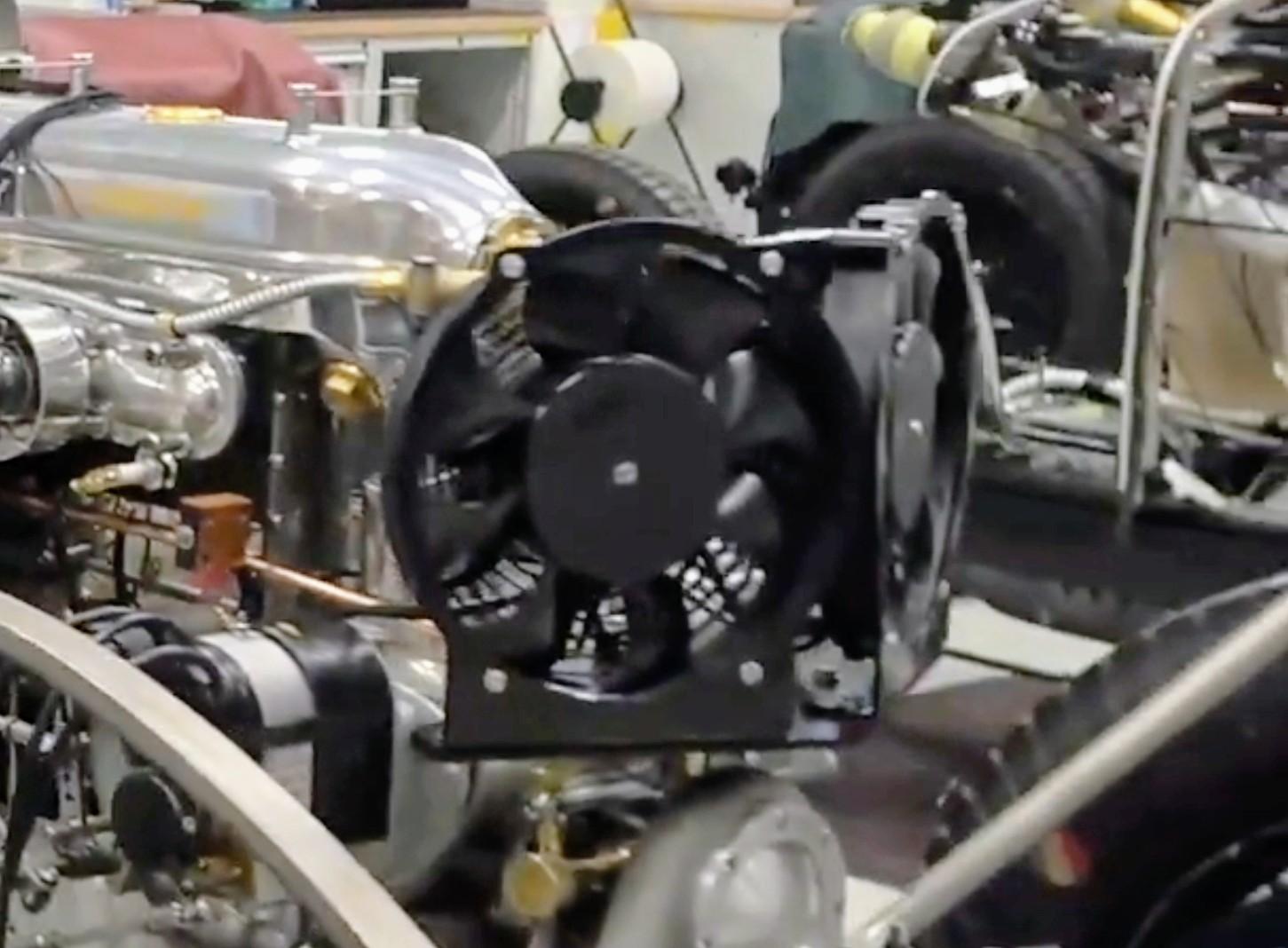
Oops, sorry bugatti. Zoet, on Amazon. Thank you very much Don. Just so nobody thinks I invented the double fan set up, here's a shot of my ref car with the fans mounted. (Sorry for the fussyness, it was taken from a video)
-
Did some more work on the throttle and magneto linkage. The parts are very small, not sure that they are printable. I would really have liked to be able to adjust the magnetos from the stator control on the steering wheel but I can't find any info on just how it's done. I know that there is a lever of some sort mounted at the end of the steering column but don't know what it looks like.
-
Since I wasn't sure how good it would work, I went with another brand. 3 different size markers for 16$ instead of 1 molotow for 22$. I wouldn't use them on a large surfaces but for small parts and touch ups they seem to do the job.
-
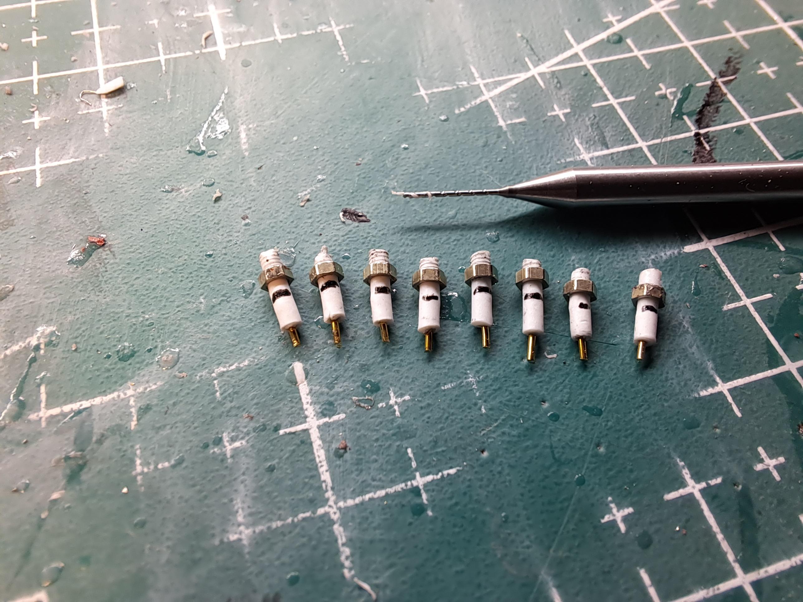
Made the spark plugs and plug wires today. Not sure I like the wire I used. At .5mm dia, the scale is good (about 1/4" scaled up) but it's not as smooth as the ones on my ref car. I'lI look for something else. also installed the now finished water pump. Very happy with the result. I started 3d modeling the magneto advance/retard ajustement linkage. Should look like this. I bought some liquid chrome markers. Very impressive !!
-
I'll see what I can do with this one before scrapping it. I'll empty it out, give it the proper shape at the bottom and insert some mesh, I'll see where I stand after that. But that's for later. For now, I'll concentrate on finishing the engine. Still have the plugs, wiring, coolant pipe, the advance/retard and throttle linkage and much more to do.
-
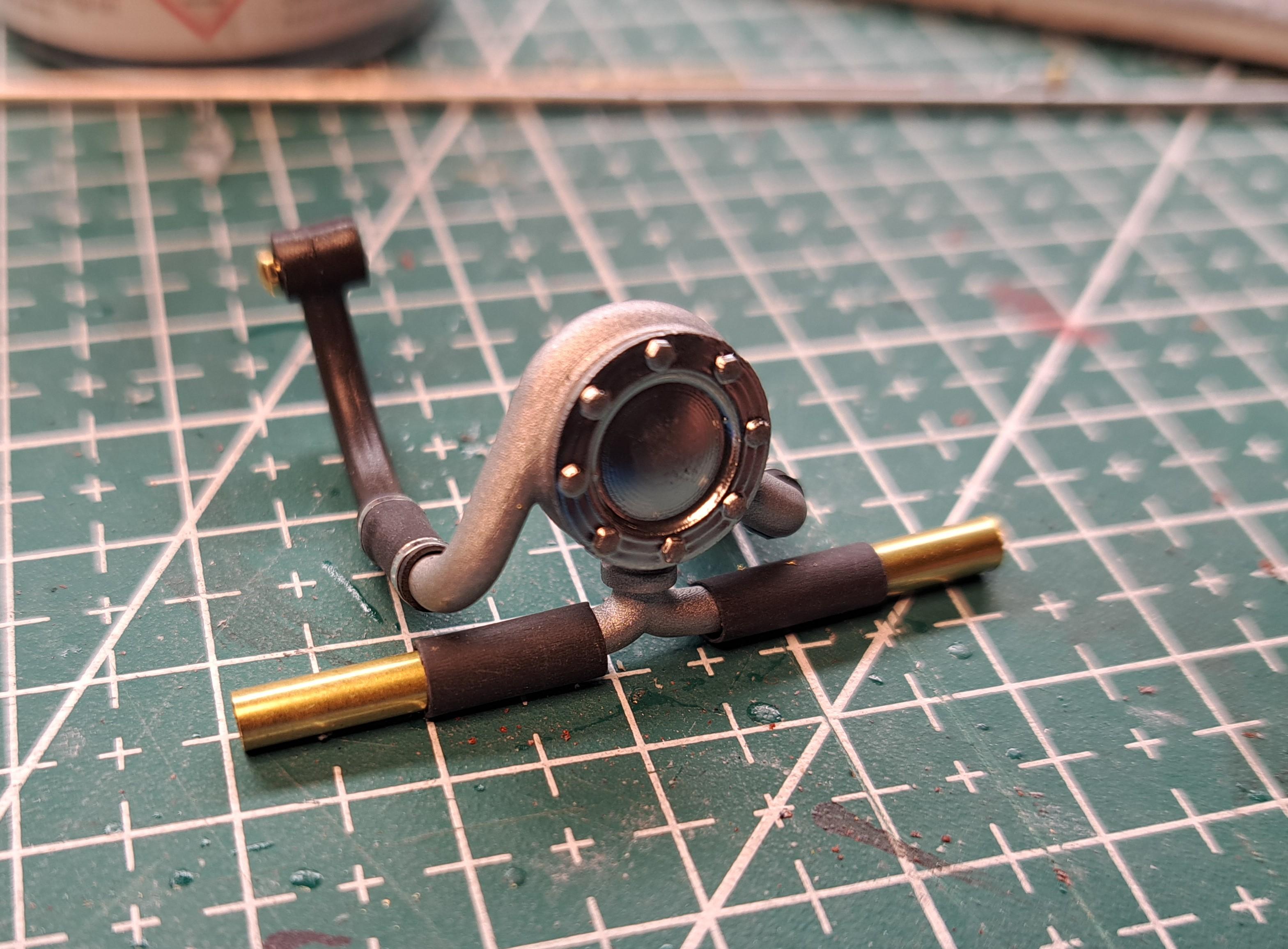
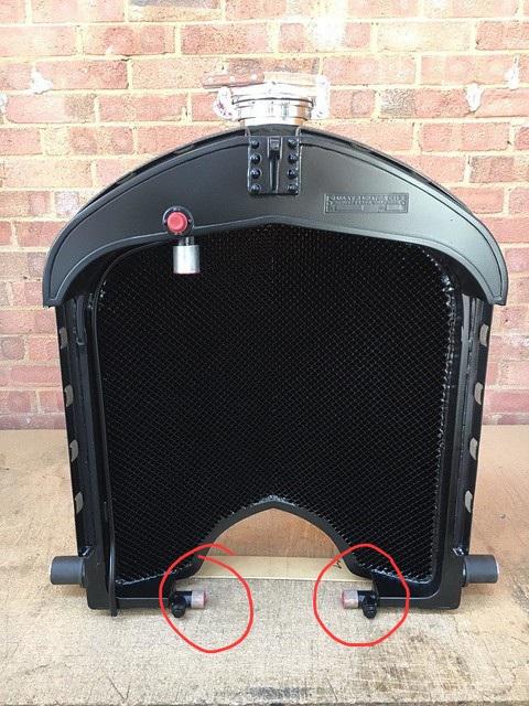
Almost done with the water pump. After a bit of research, I finally figured out where the lower 'y' connection goes to. They connect on bottom of the radiator Unfortunately, the kit's radiator doesn't provide these connections. I can see more major modifications in my futur
-
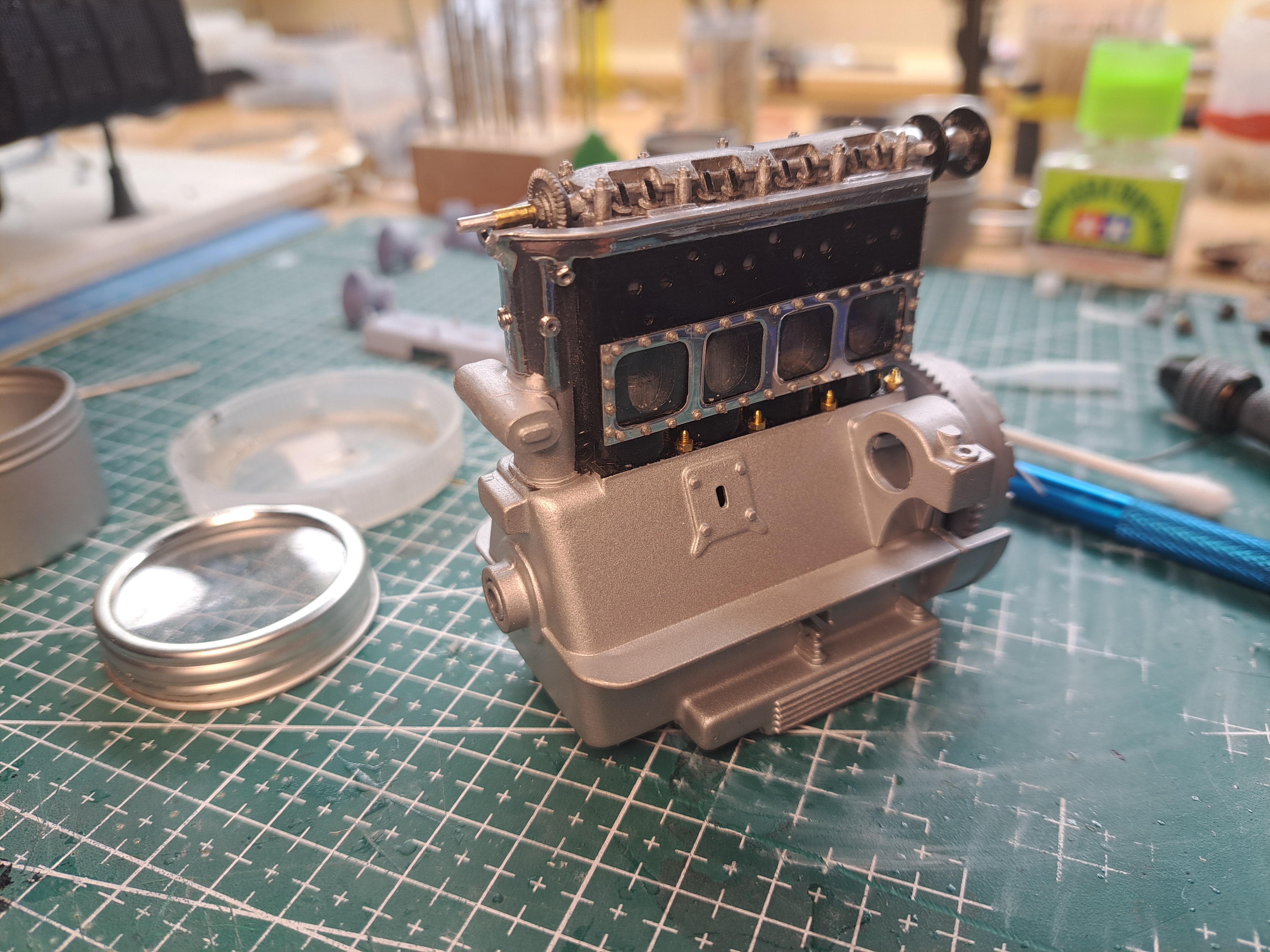
I finished installing the side covers on the engine block.
-
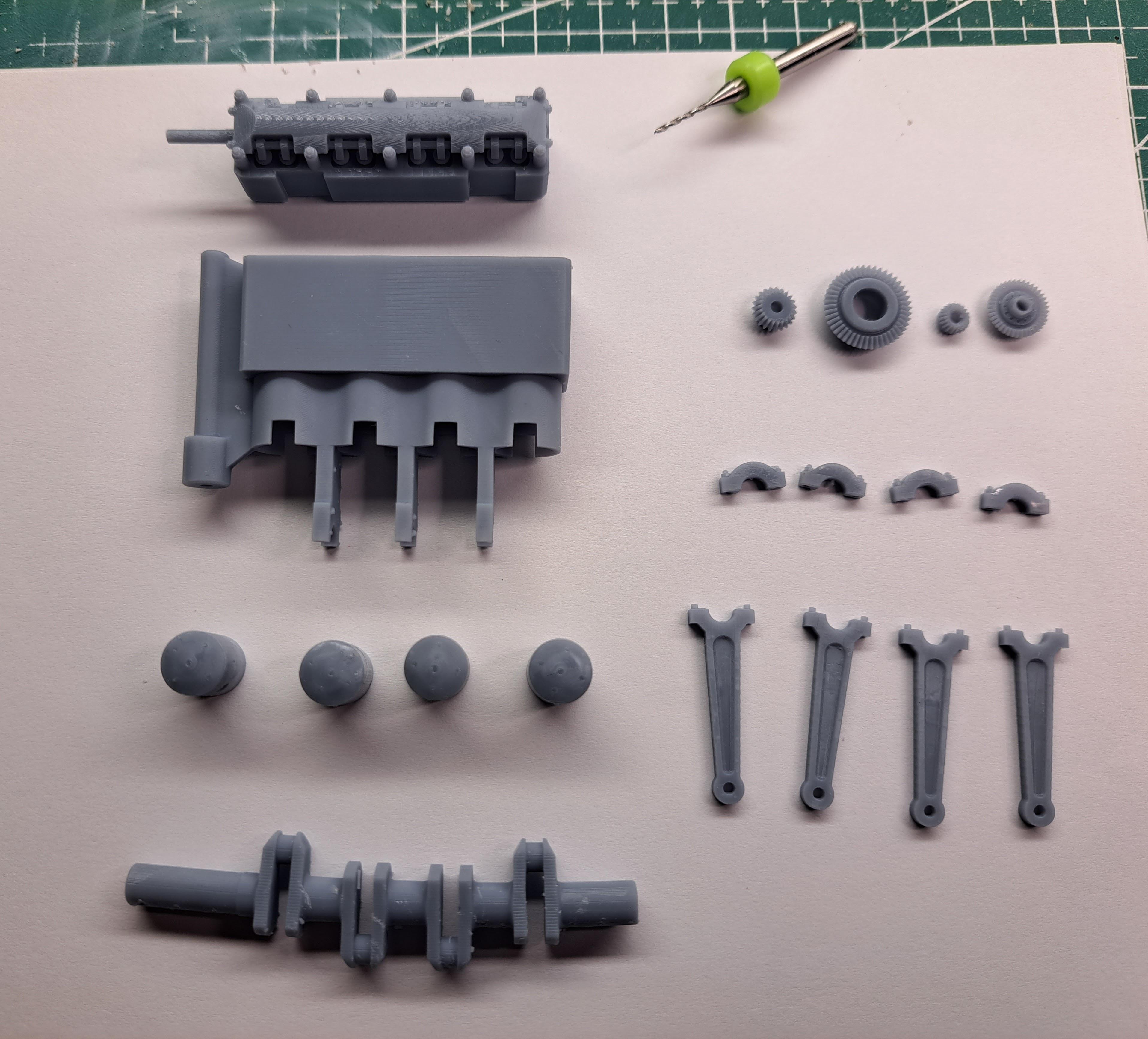
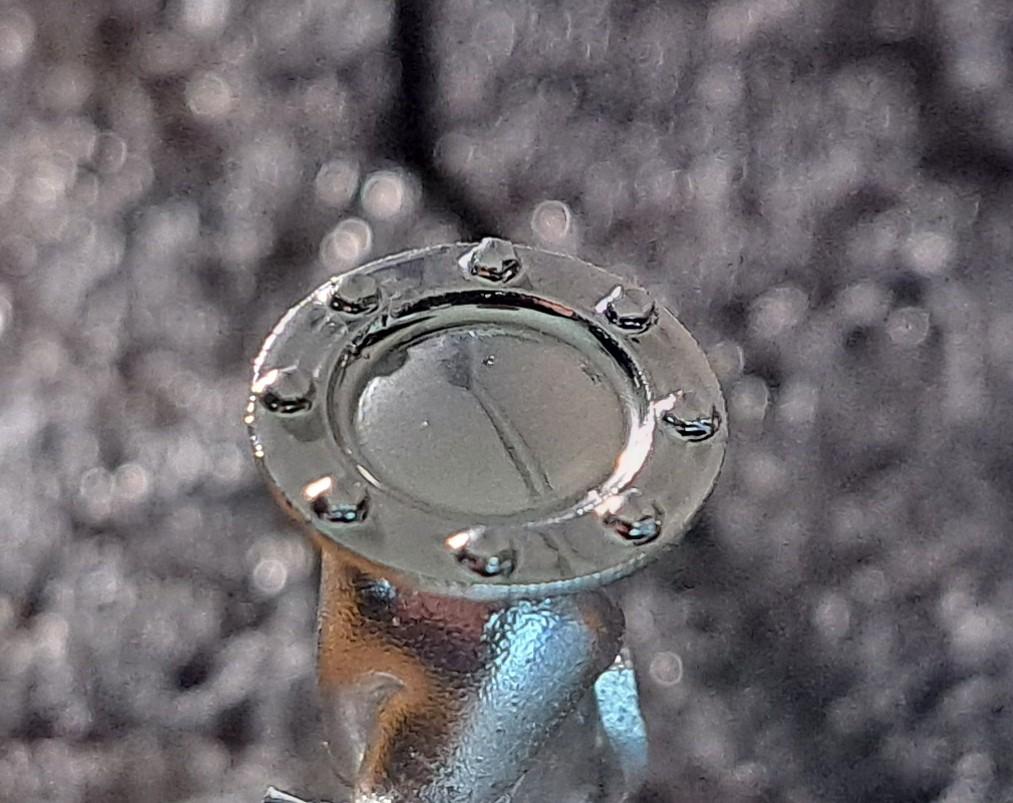
Hello everyone, I just wanted to remind you all that I offer my 3d modeling and 3d printing services. I can design custom parts for you to enhance your build. Here are some exxamples of what I've done. FOR THE AIRFIX BENTLEY BLOWER Engine inner parts 20231009_192359.mp4 Bulkhead assembly Pedal cluster Drive shaft Steering link Wheel hubs with brake drum knockoff butterfly and center bolt (for rear or front) Brake adjuster Fuel pump Tach drive Hand brake Intake manifold Steering wheel with stator control Water pump Fan assembly Miscellaneous parts You can email or call me for more info and to discuss your needs. fr.faucher@videotron.ca 514 947-4842
-
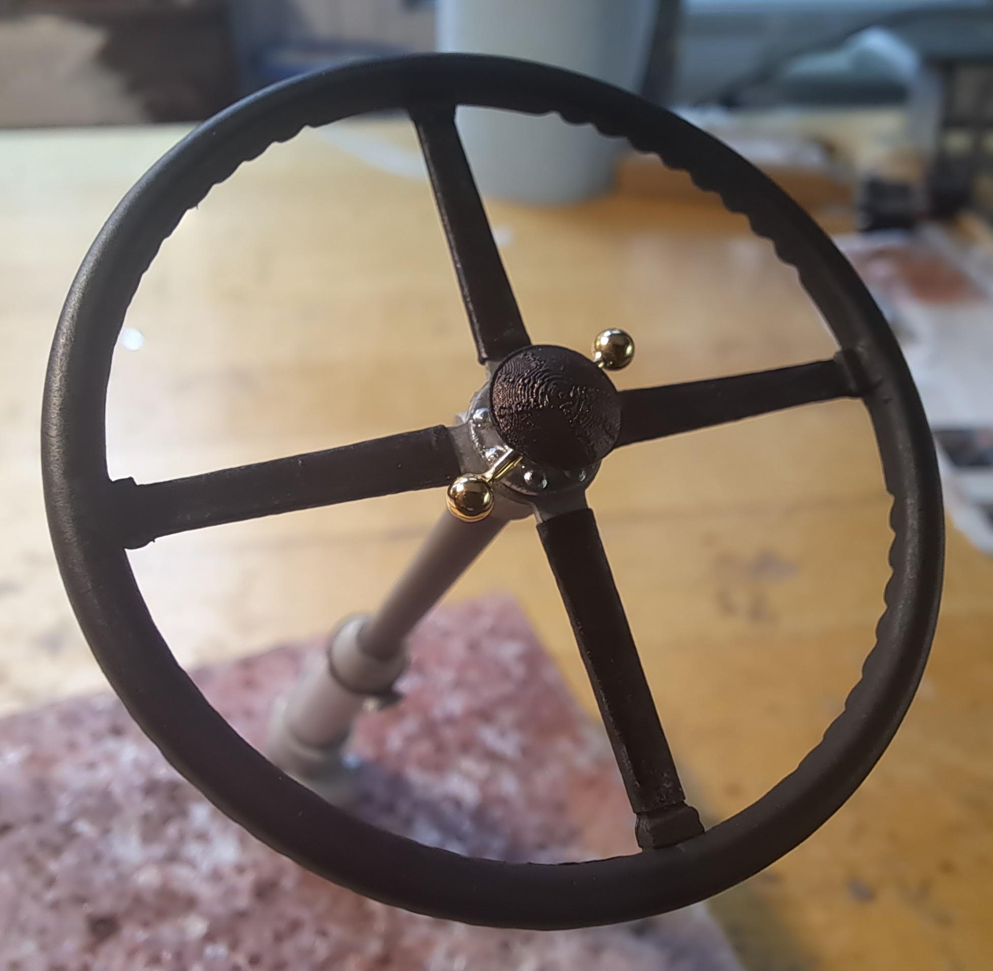
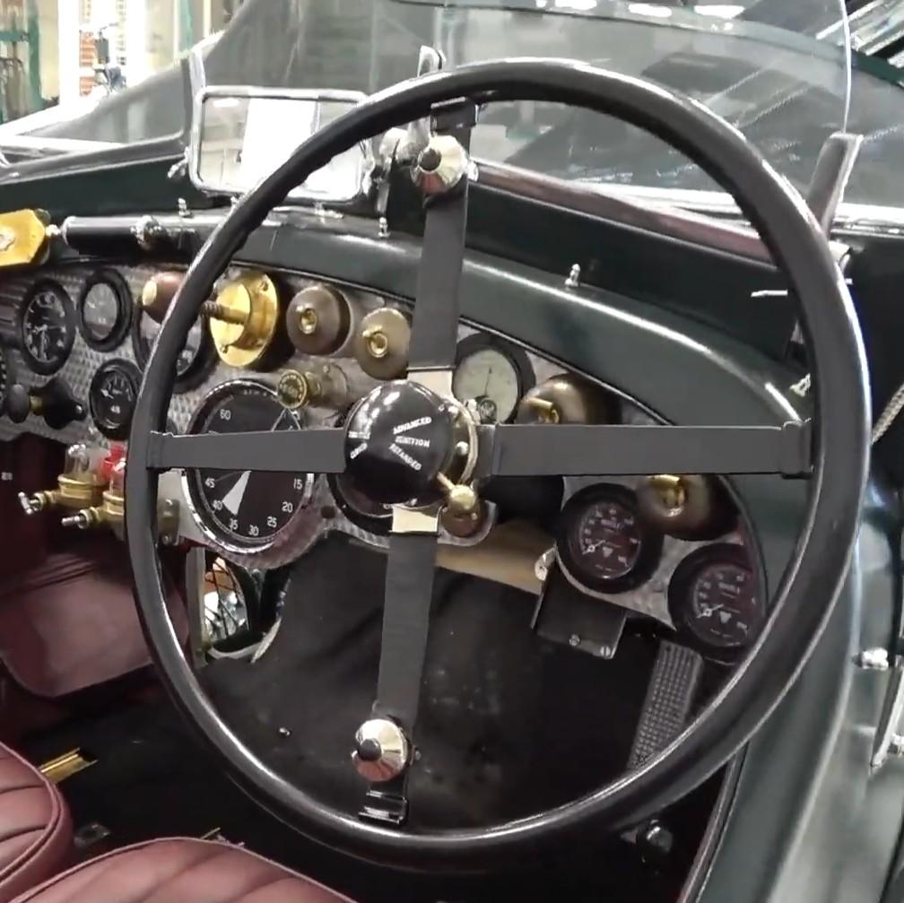
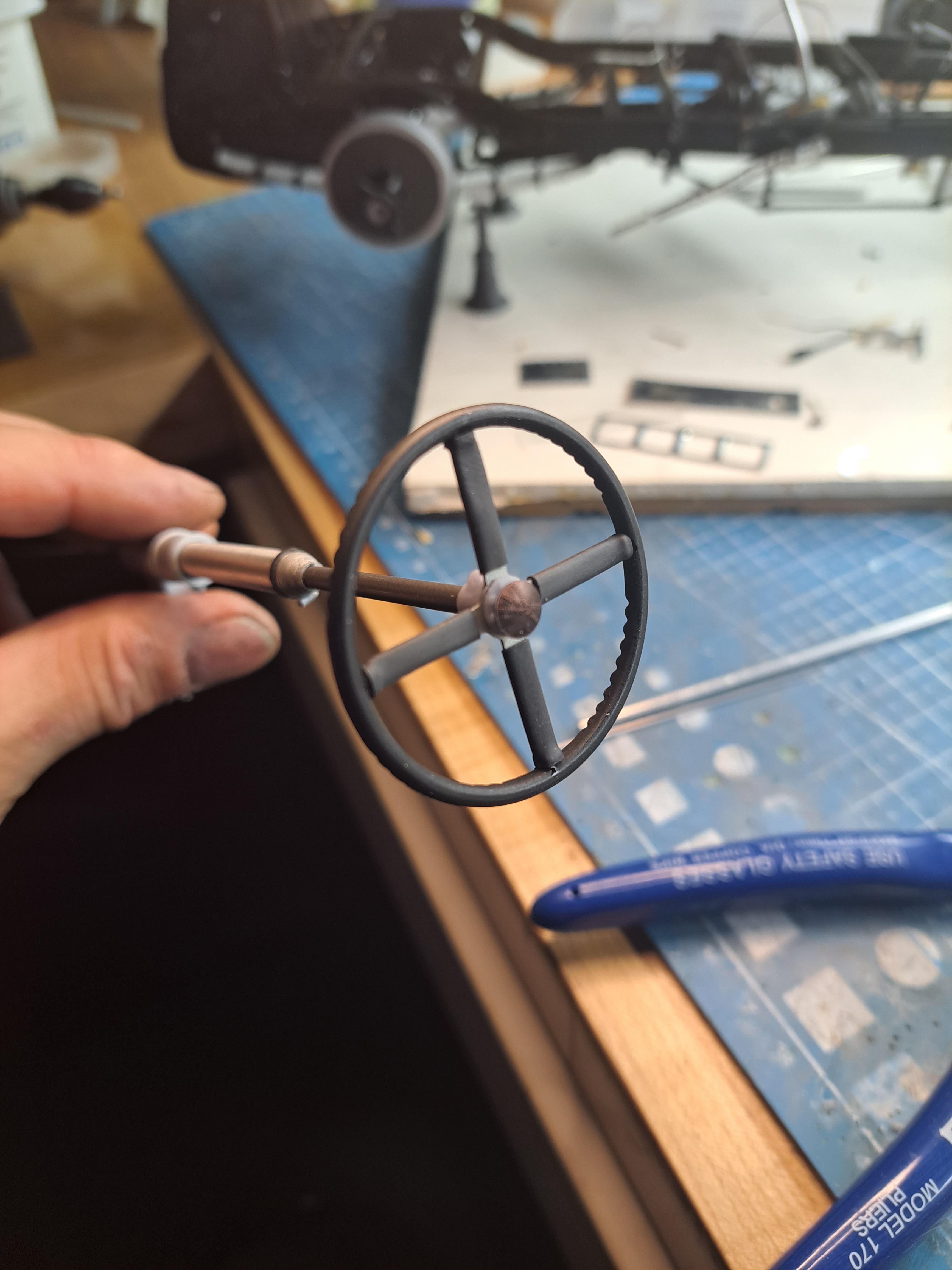
I assembled the brake adjuster today, I would need a strongher return spring to properly stretch the cable but my parts would not take the stress. But it still fonction as it should. The cable can be tensionned by turning the adjuster knob, this would have compensated for brake pad wear. Here are some progress and finished pictures and a video of the working mecanism. 20231022_210140.mp4 Also redid the steering wheel using the rice tape described in my previous post.
-
I'm rethinking the steering wheel. I really don't like my first try, the heat shrink is too bulky and out of scale. I even tried heat shrinking over a smaller section arm but that didn't work either, the heat melted the plastic. So I'm scraping the shrink idea altogether. I'm going to try using super thin rice paper tape (about .002" think) to simulate the plastic cover used over the spider arms. So let me remind you of my goal. My first try with the head shrink. my first rice paper test (not as bulky as the heat shrink) the rice paper and newly printed wheel center l'm also slowly advancing with the engine dress up, I've got the second aluminium cover plate installed and drilled. Still have to put the bolts on.
-
Not much done today. Fan assembly done. And water pump face plate mounted. It was noted that the steering wheel arms are maybe a bit big and I have to agree. I'll reprint the center portion and see it I can heat shrink on a narrower arm and maybe compensate with the print the too thick heat shrink.
-
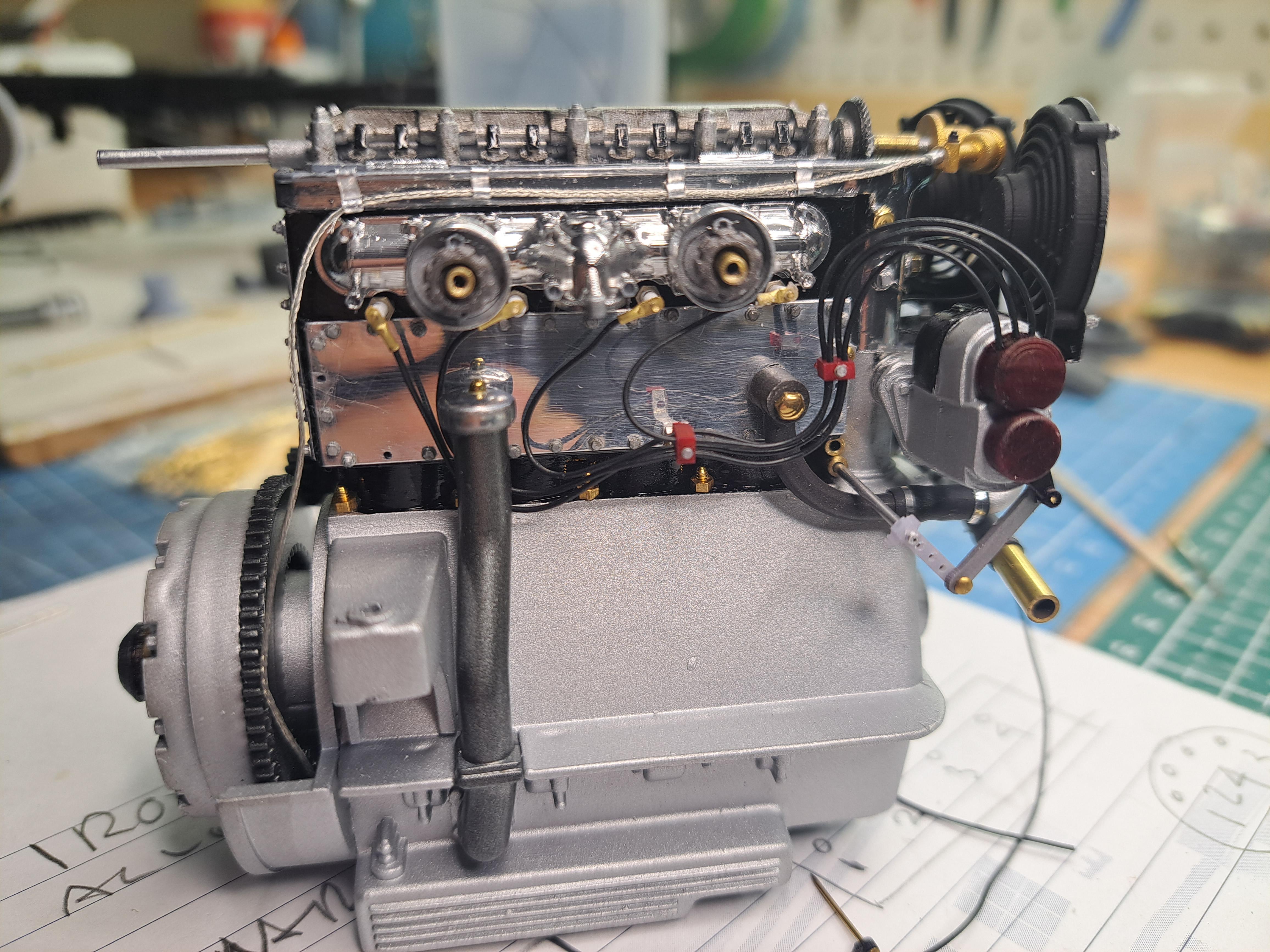
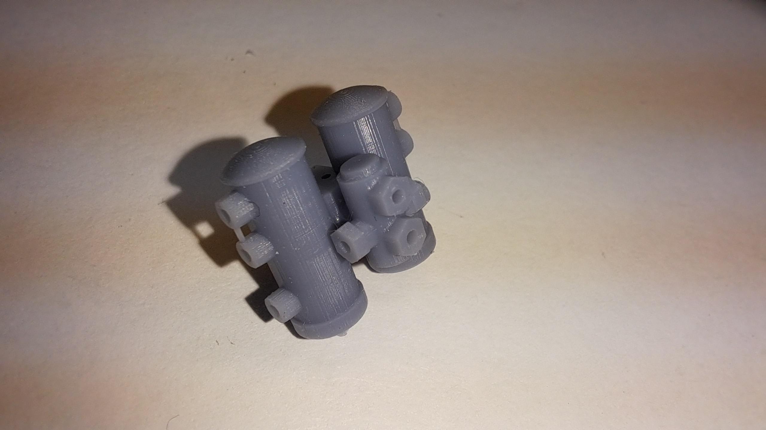
Up date time, I've been busy on many fronts at the same time. 1- Due to "peer pressure", I remodeled the water pump and from cover to better reflect the picture posted by nick. I had it resin printed instead of trying to print it myself. The result should be alot better. The real thing The 3d model The new pump (still drying) And the cover plate (also still drying) 2- I started to assemble the brake ajuster but I'm still missing a few aluminium parts that I need to fabricate. 3- I modified the steering wheel. The one on my ref car has plastic covering on the 4 spider branches. In order to do this, I removed the center portion on the wheel, printed a new one, inserted 4 heat shrink tubes, glueds the 4 branches to the wheel and shrunk the tubes. Looks ok to me. I also started assembly of the stator control that mounts on the steering wheel. My ref car steering wheel The kit's wheel (sorry for the poor picture) Heat shrink test All the parts ready to assemble The finished wheel and with stator control 4- received the fans. I had to make a sanding jig to sand the mounting surface of the fan housing. They look very nice and they spin! Jig and parts before sanding Housing in jig Fan assembled Back from paint 5- started to instead the gazilion bolts on the engine block aluminium cover plates. 1 done. 2 more to go. 6- the engine block is all painted, lower portion aluminium. Core black and top chrome. 7- finalized the handbrake release lever
-
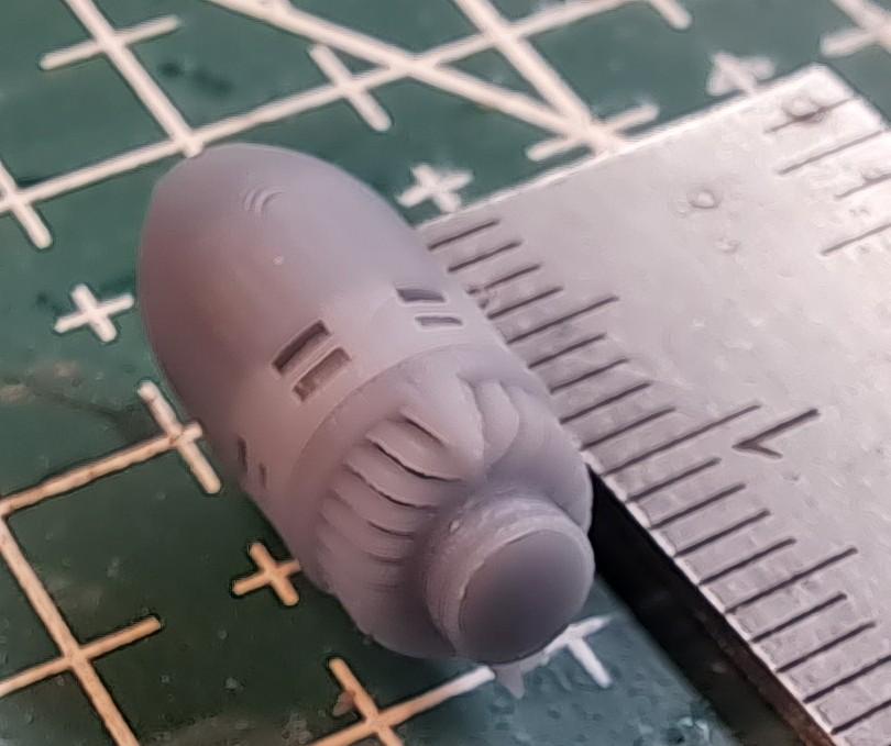
I recently was commisionned to make 10 fire truck siren. 1/25 scale model Federal ZL. They are highly detailed and ready for finish. unfortunately for me, my client is a no show. They are available.