François
-
Posts
489 -
Joined
-
Last visited
Content Type
Profiles
Forums
Events
Gallery
Everything posted by François
-
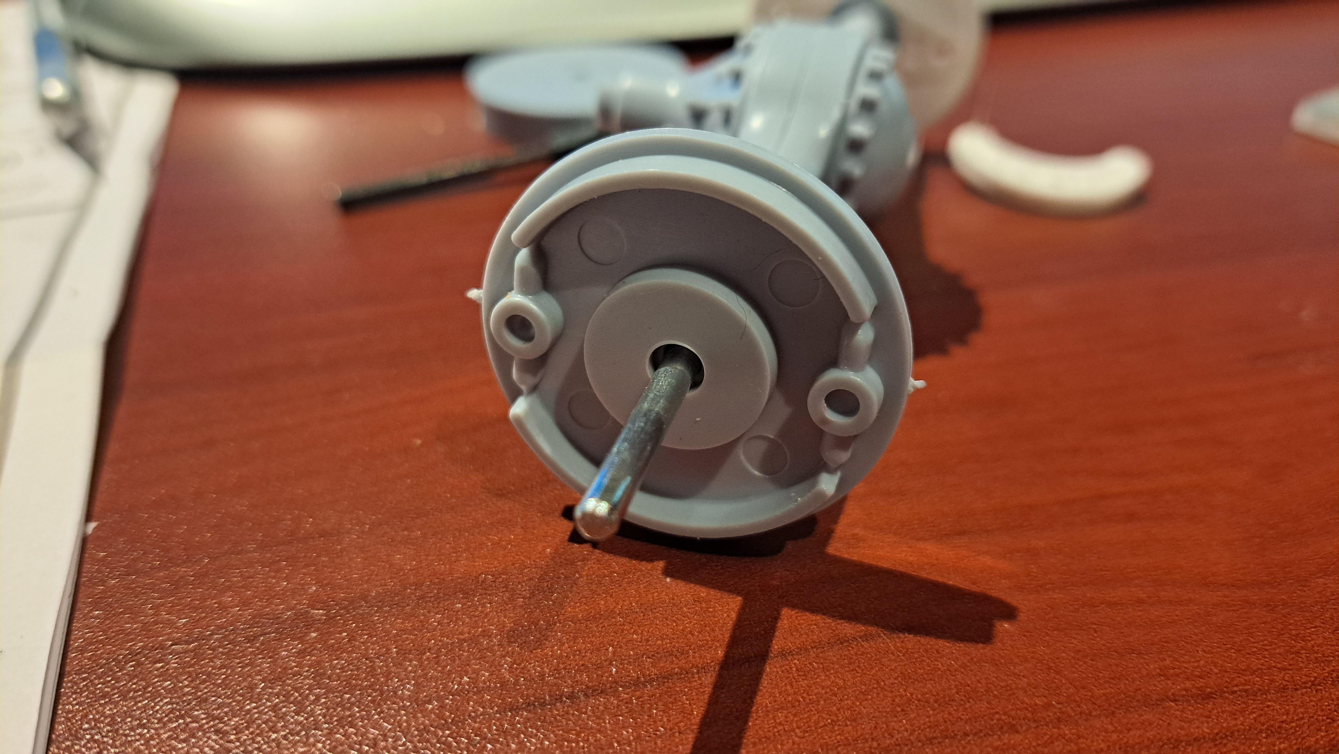
Did the micro springs for the brake segments using. 003" wire. 20240103_095231.mp4 Reprinted the brake drums

-
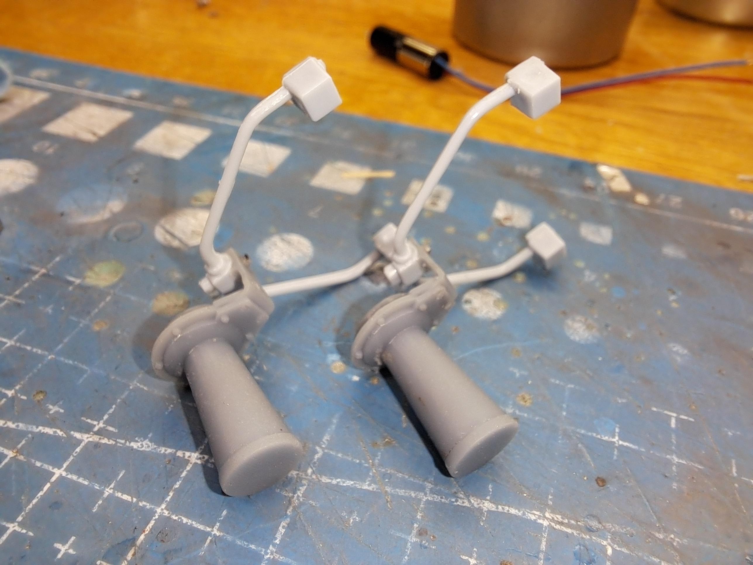
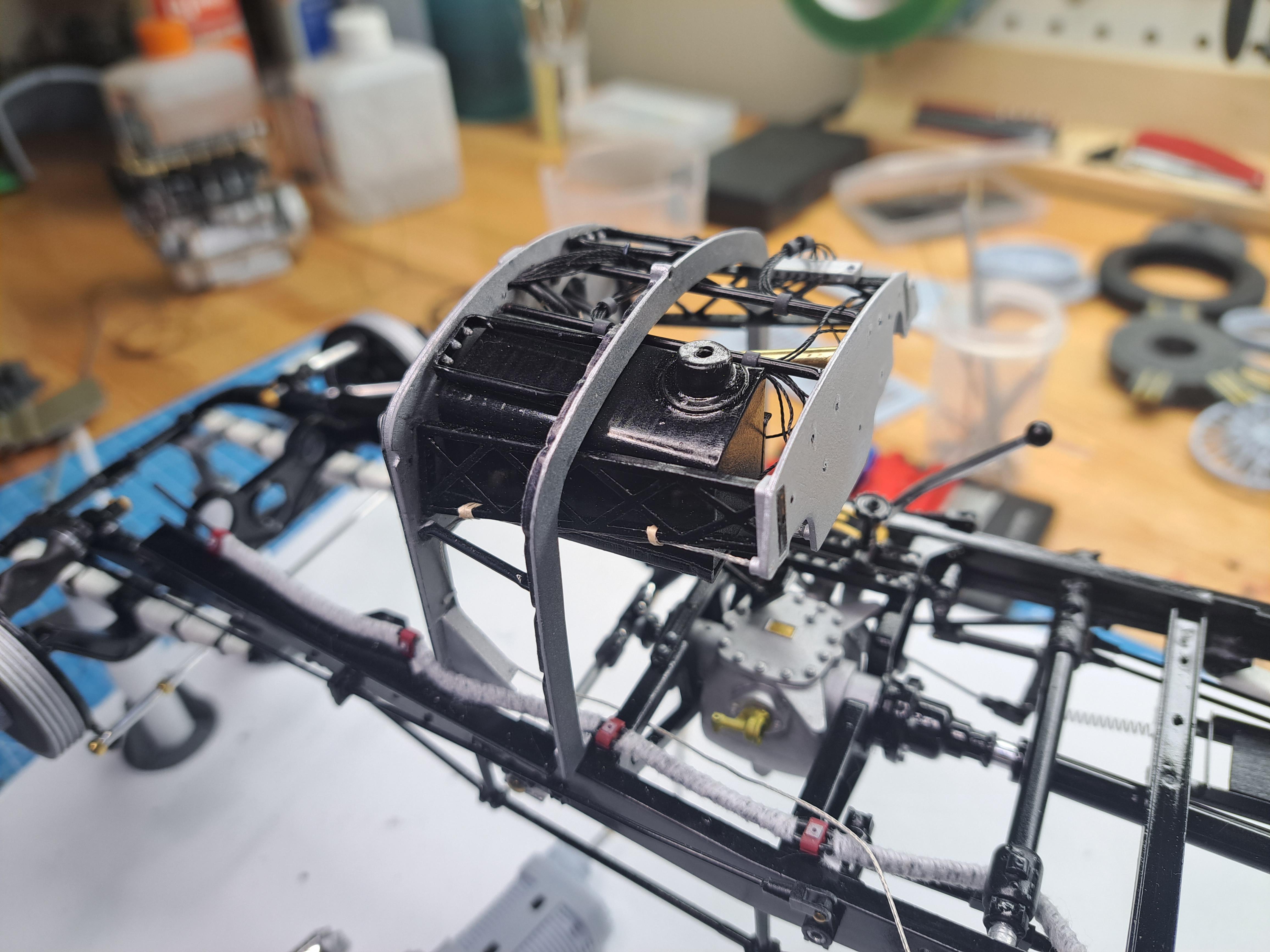
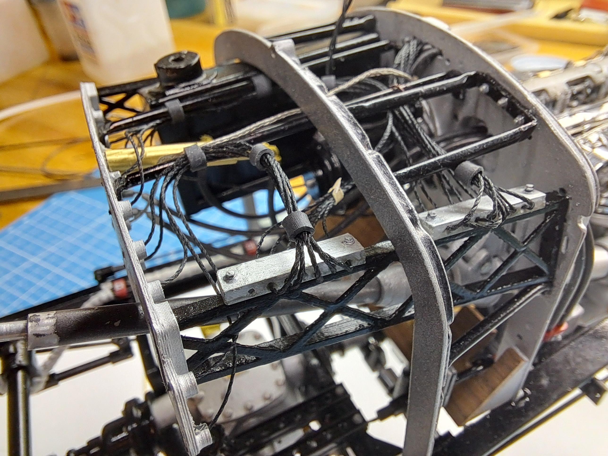
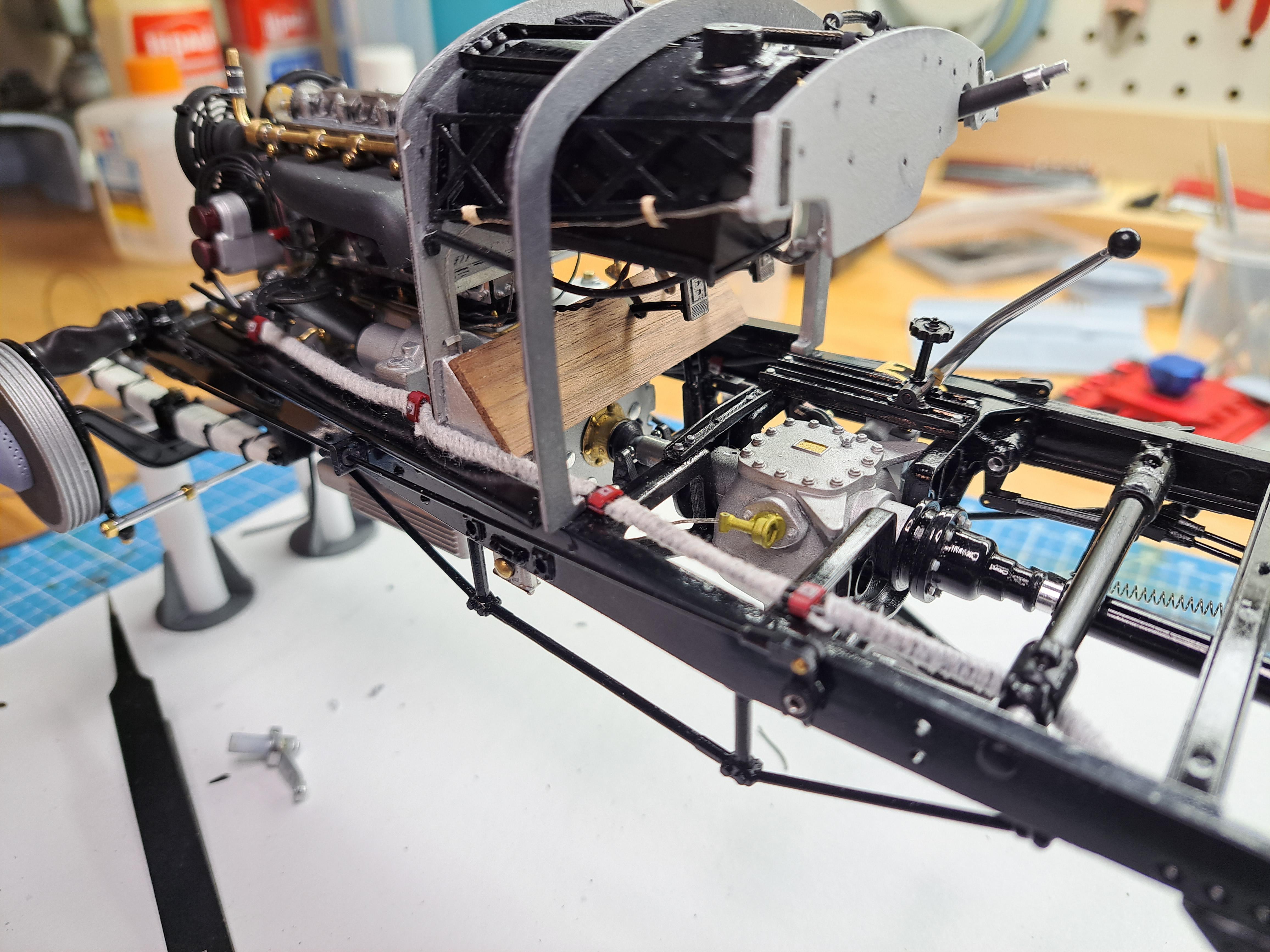
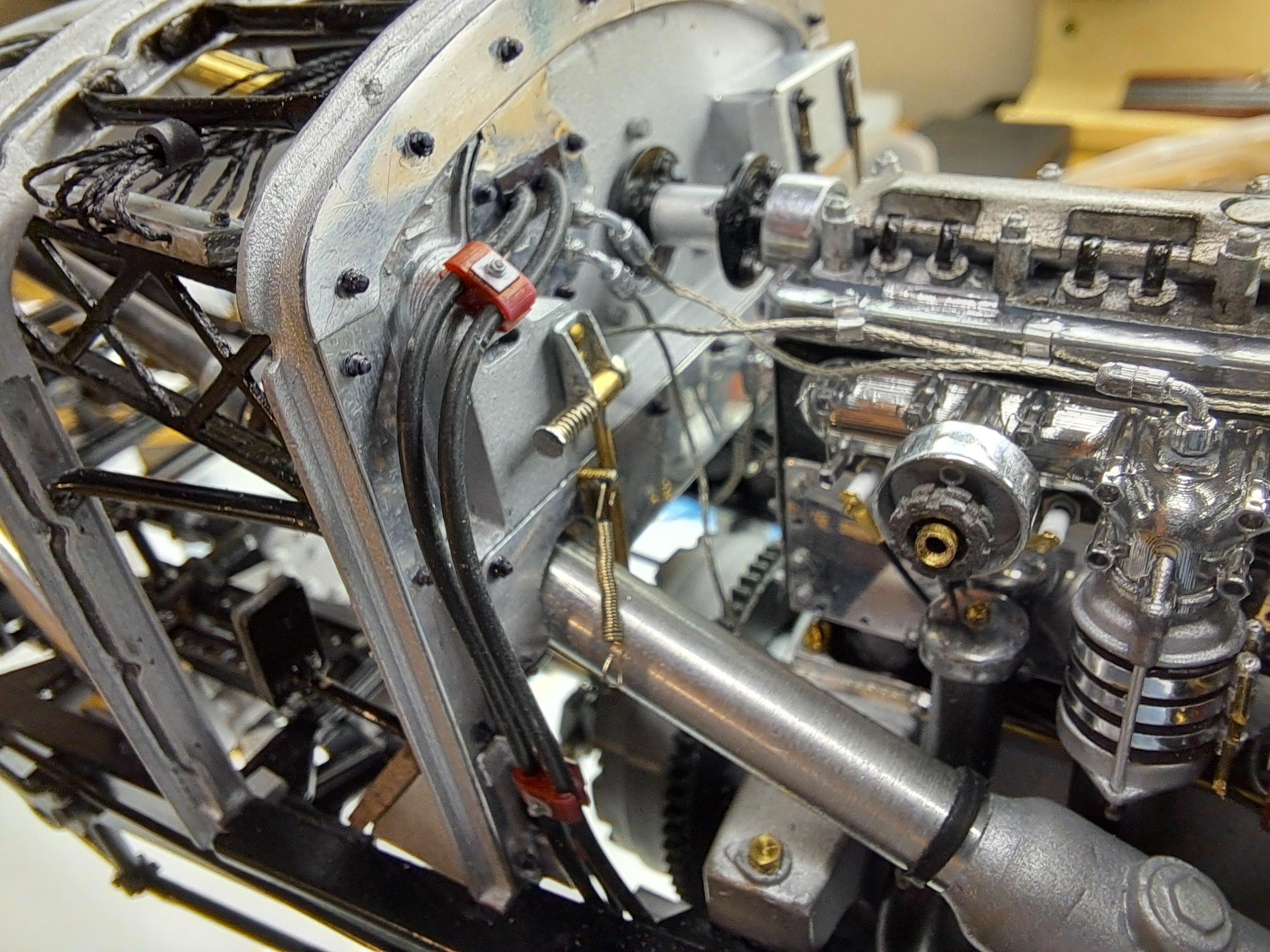
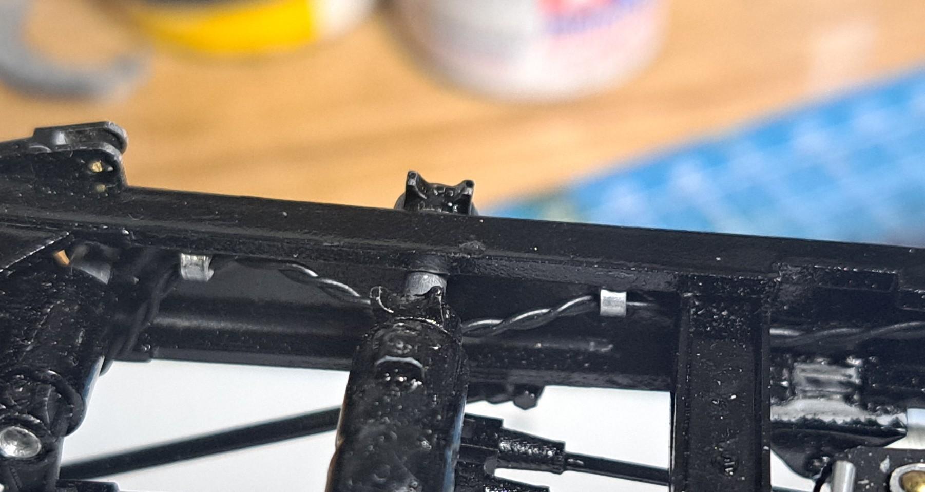
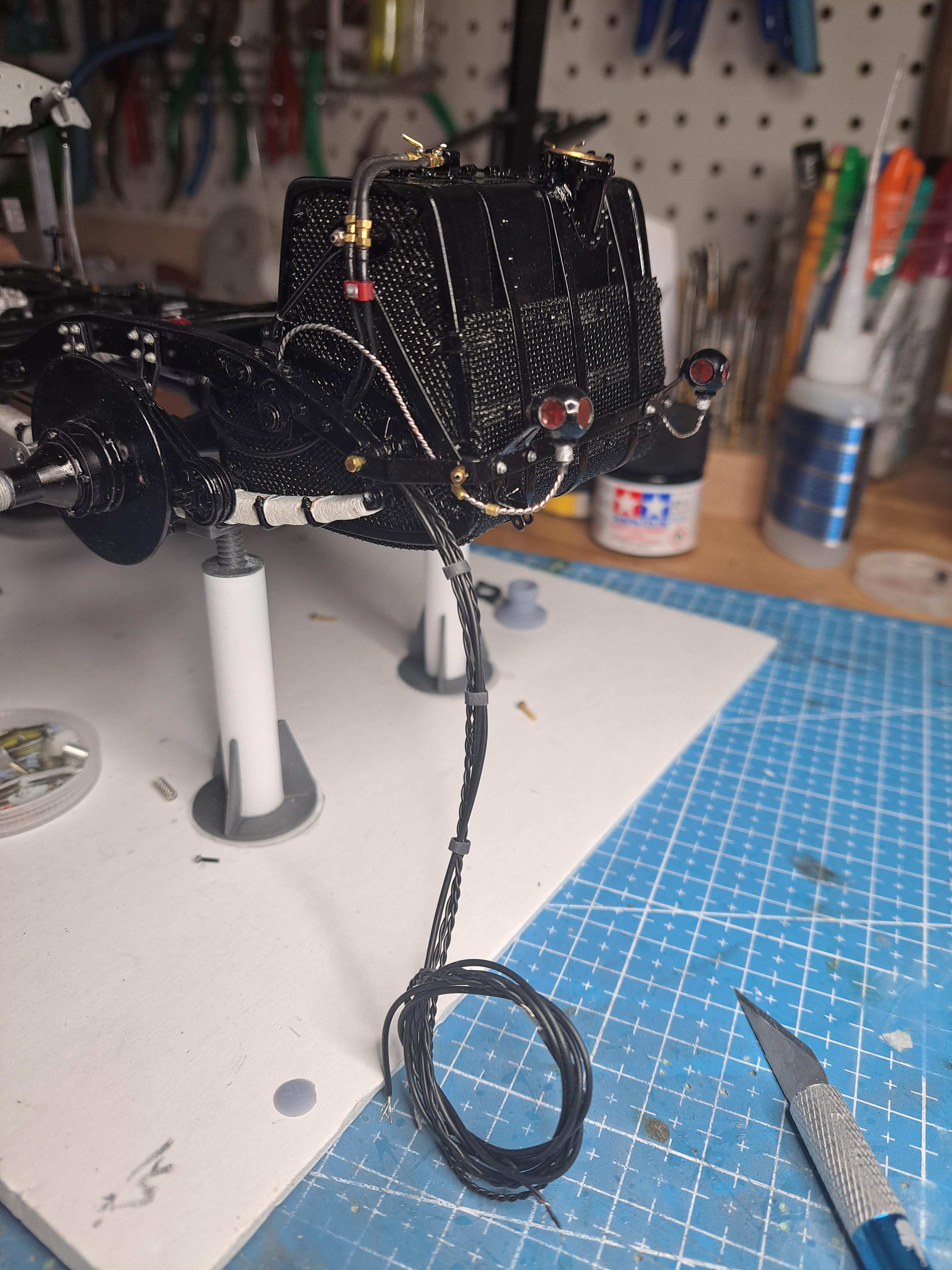
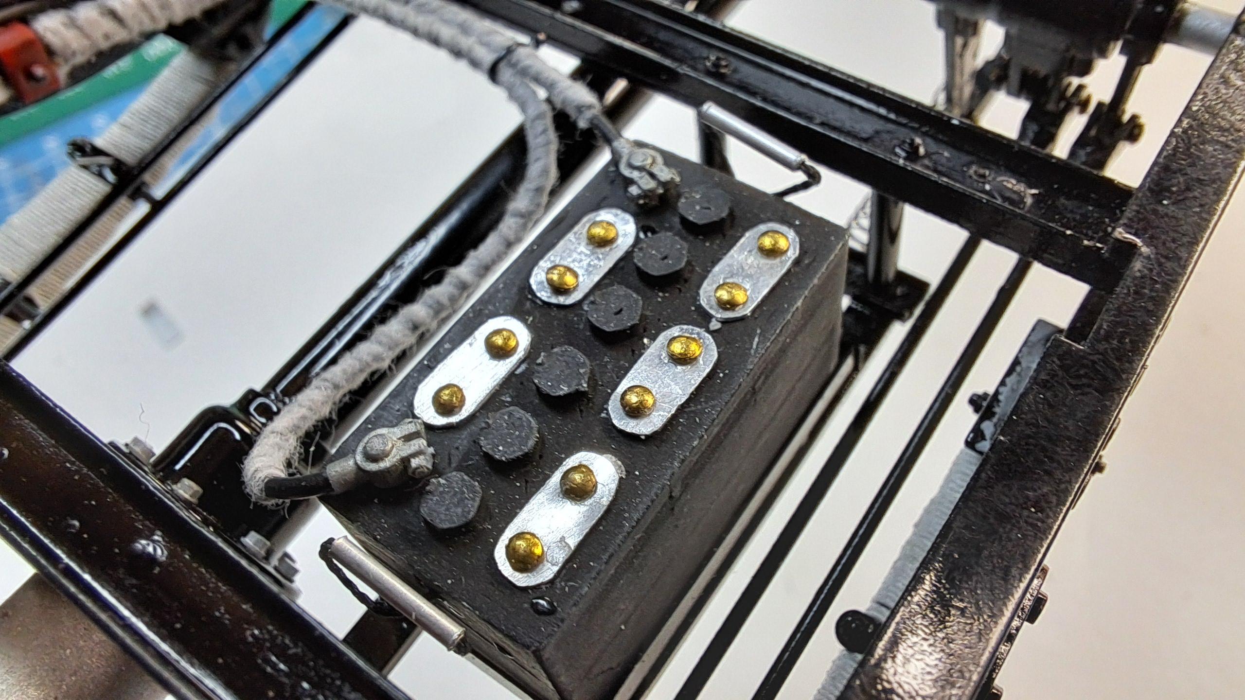
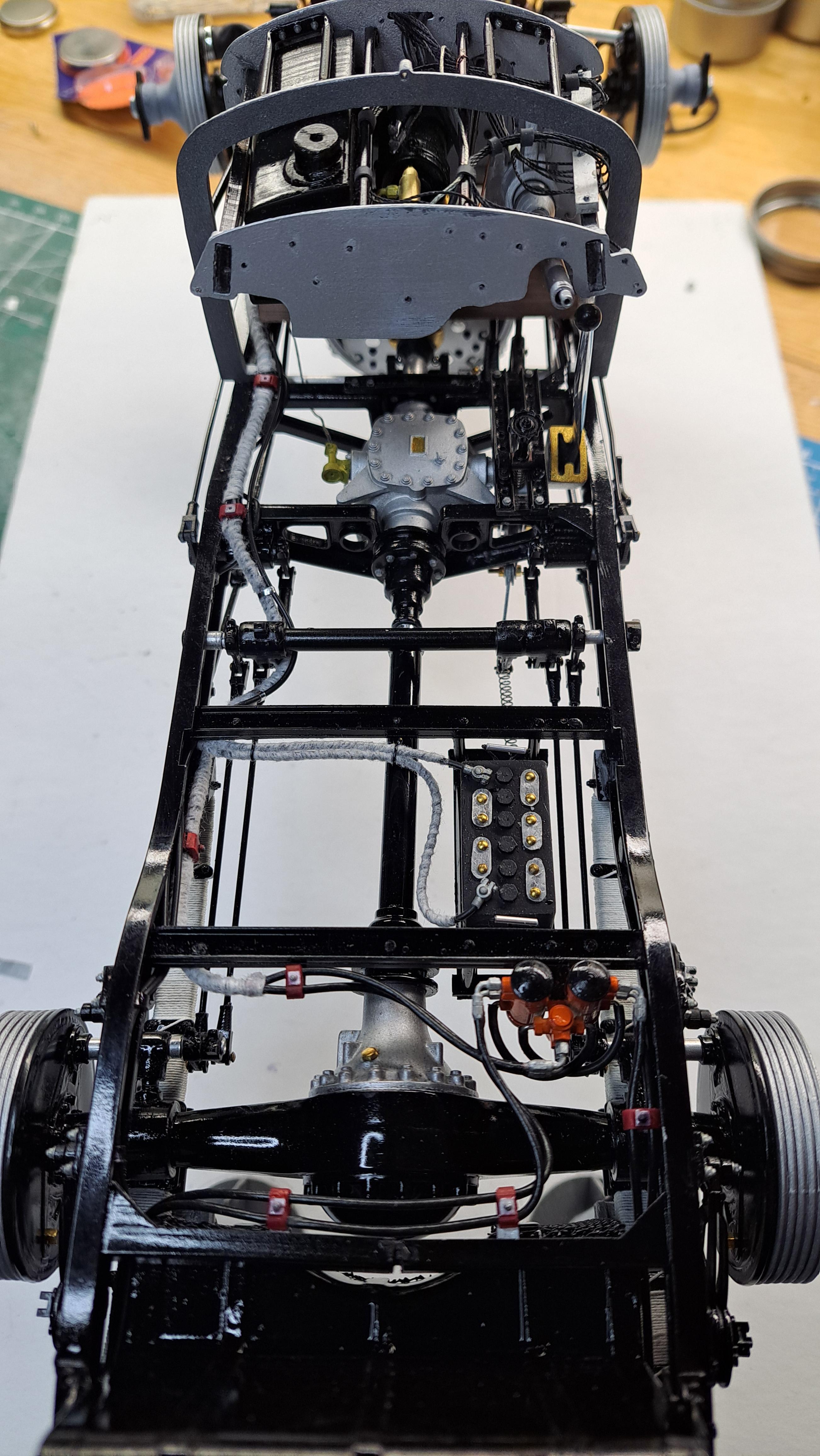
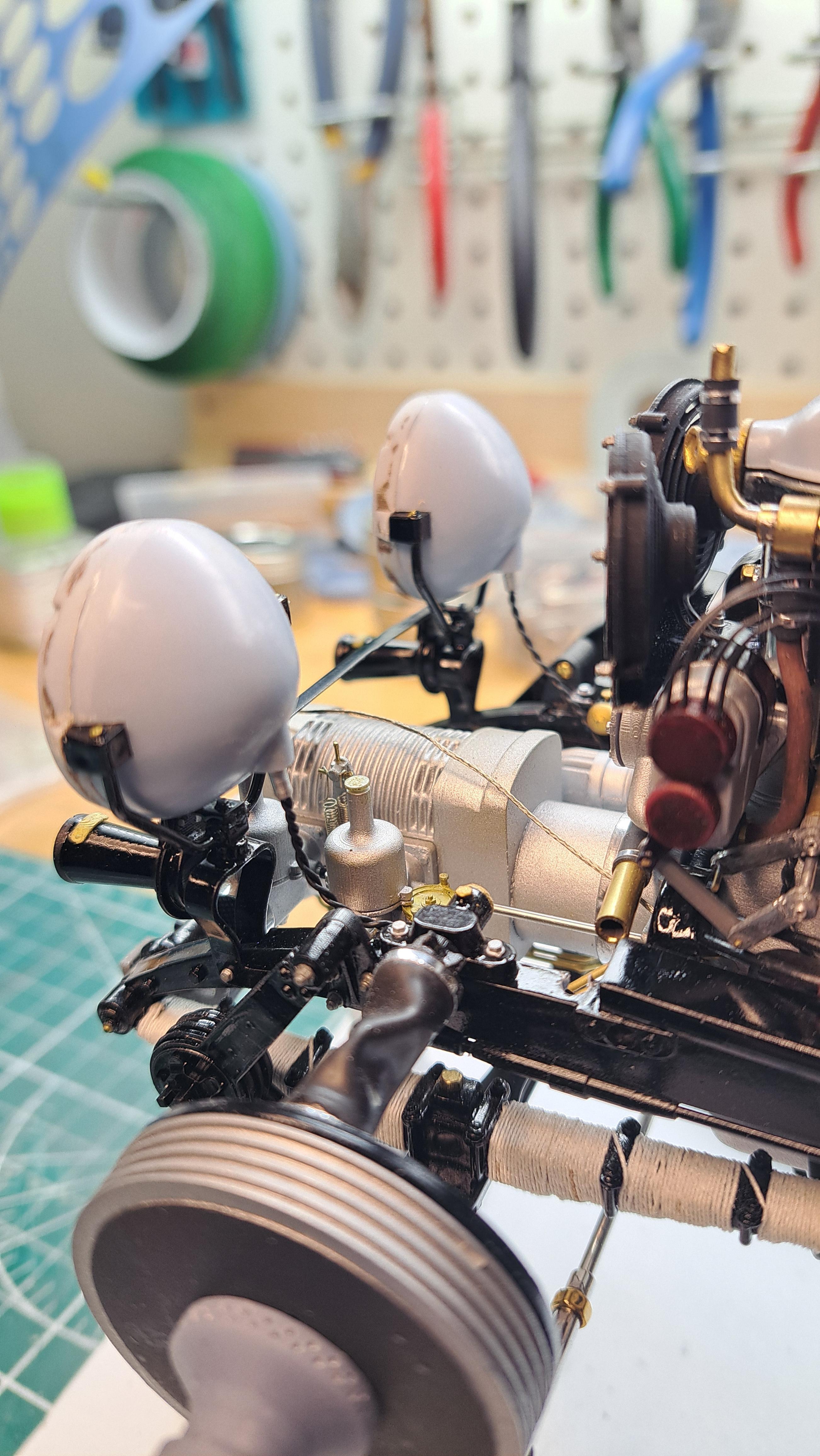
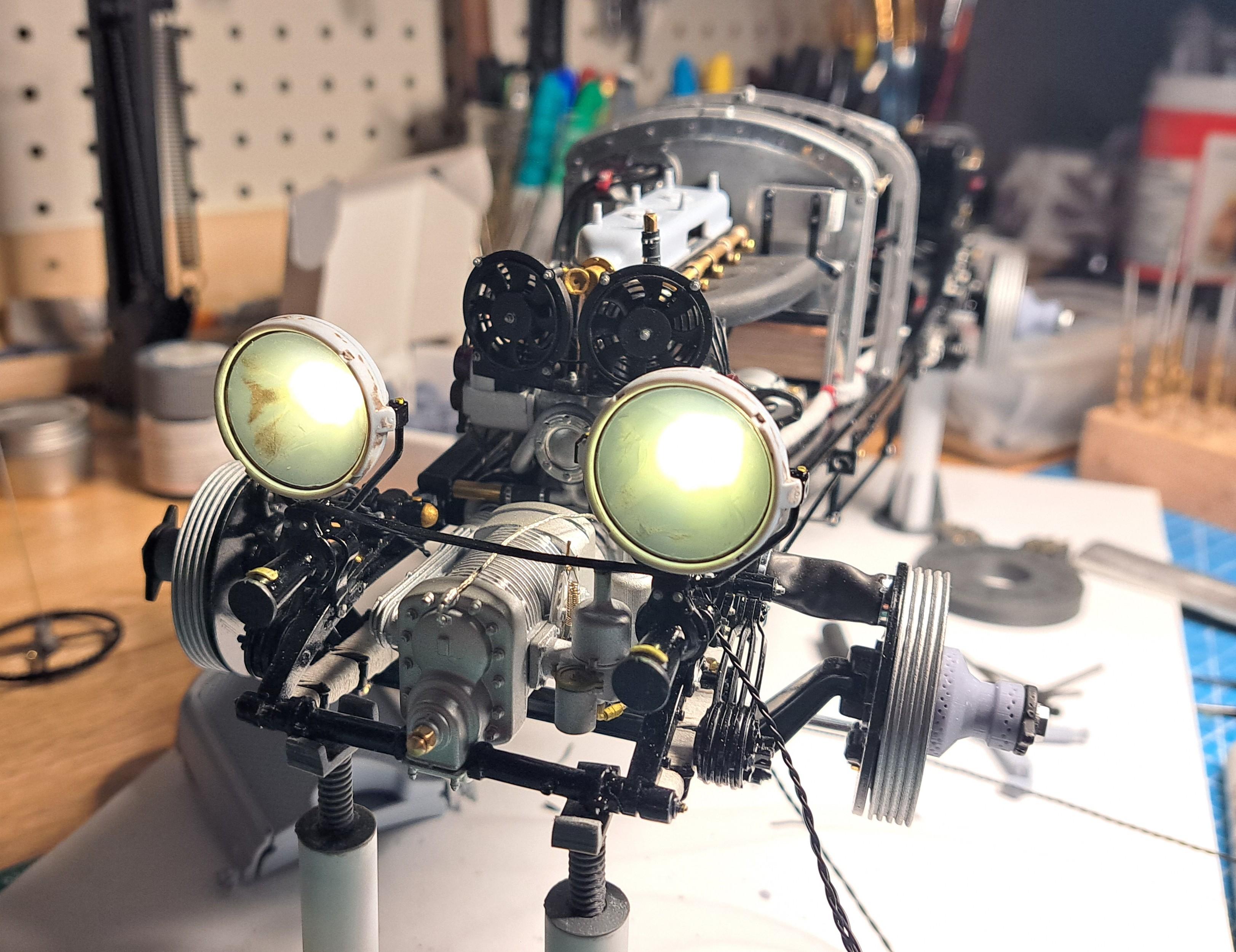
Yes, they will be spring loaded. I also need to fine tune the brake pedal in order to give it a bit more travelling and I should be able to see mouvement on all 4 brake pads. I finished wiring the head lights. It wasn't easy to hide the wires but I think it came out ok. All the wires (gearmotor and lights) come out of tge frame on the left side of the gas tank. They make a nice little wire harness that will eventualy go to a control panel mounted on the outside of the display case. I still haven't decided if the harness will run on or go thru the mirored display floor. It will depend on the look I want. I also added 2 red wire clips to hold the battery cables.
-
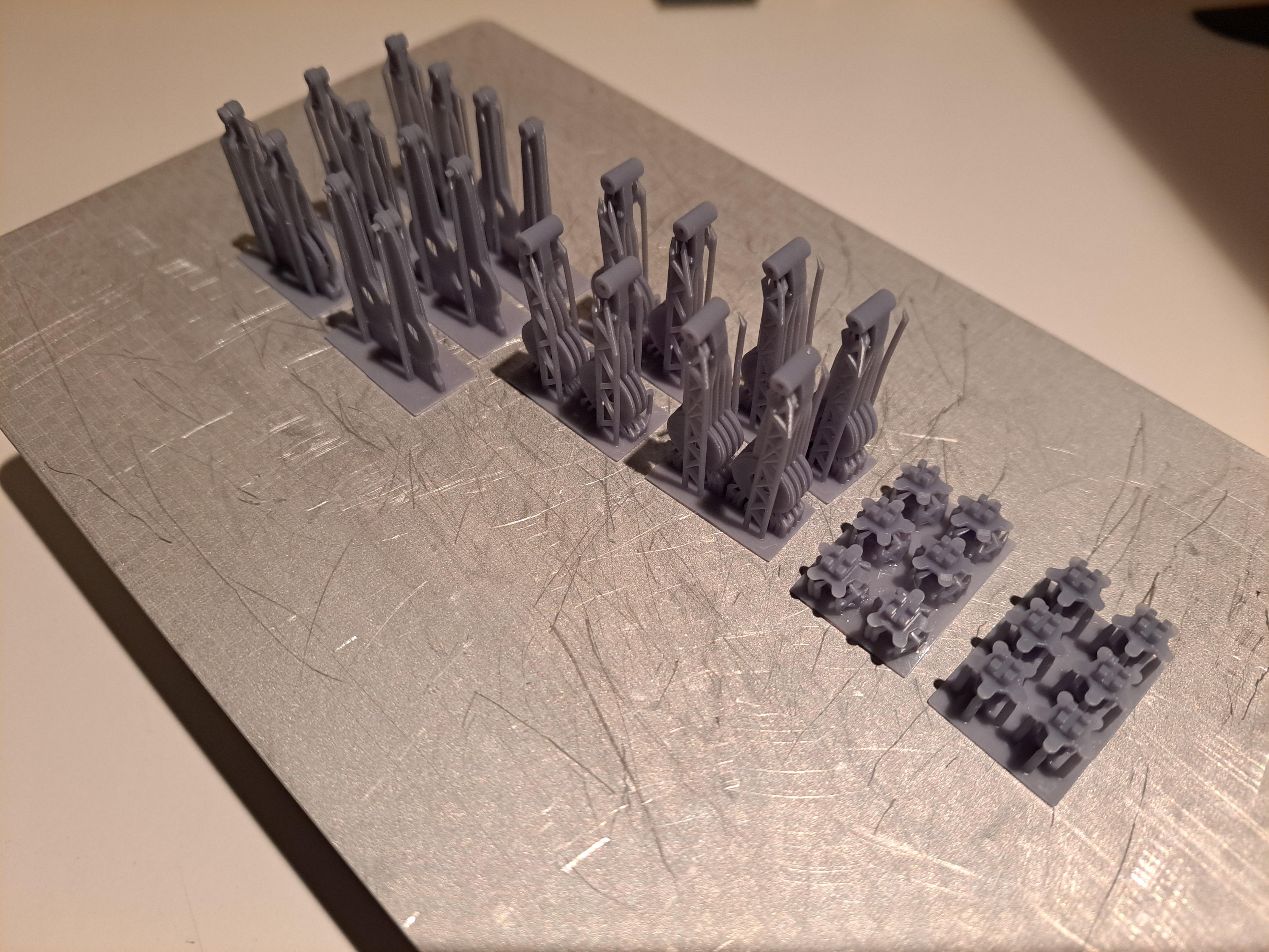
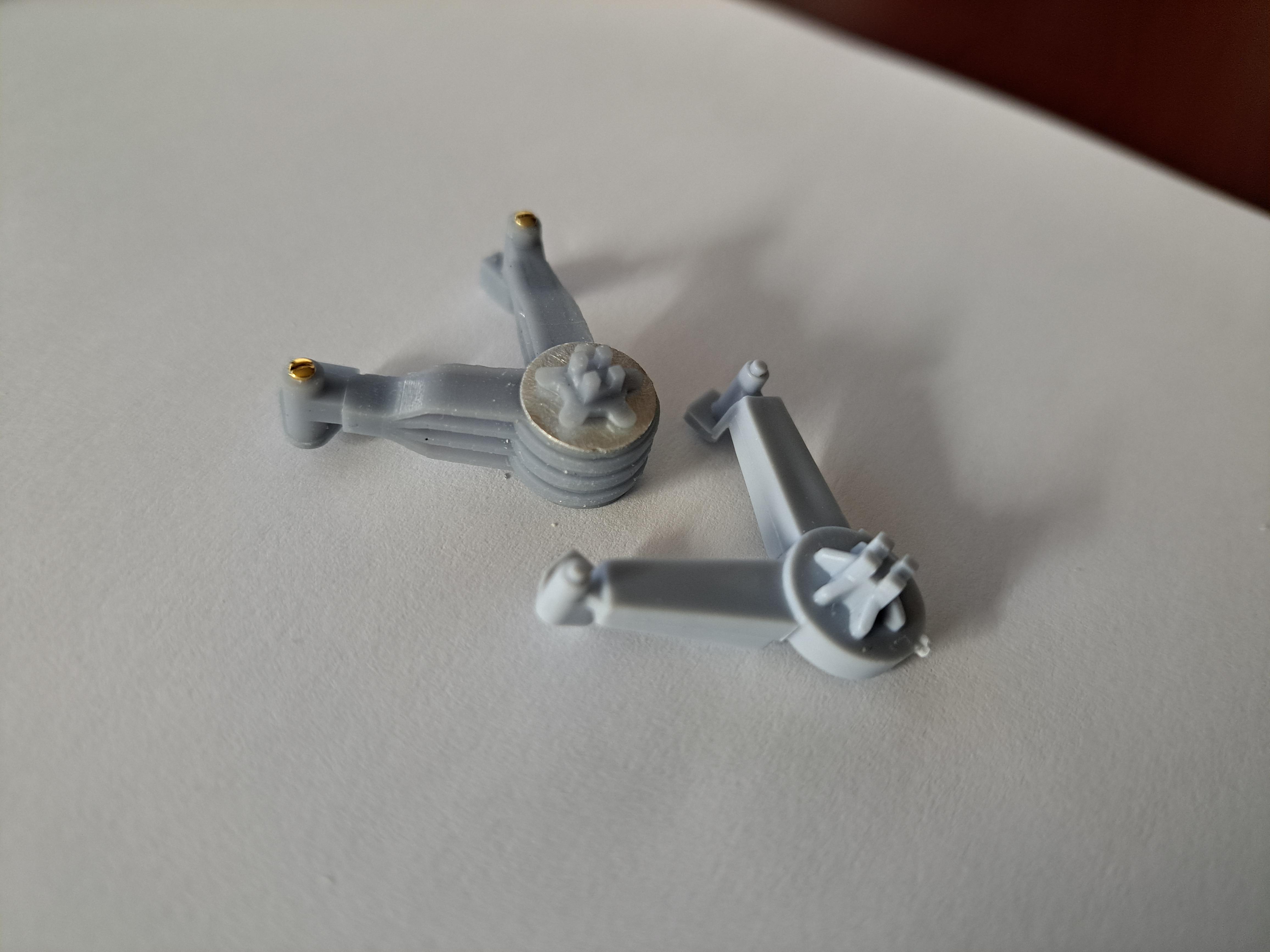
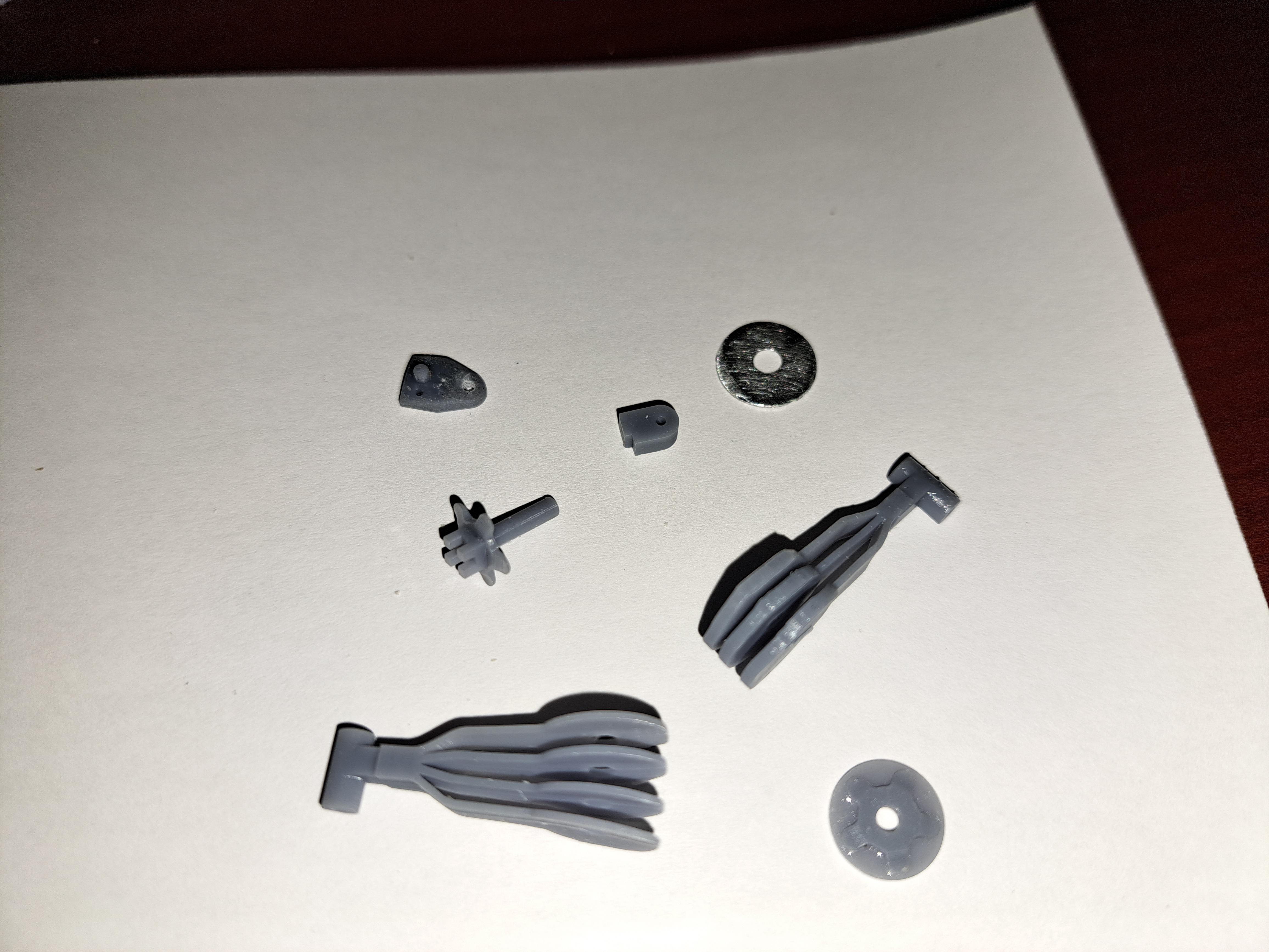
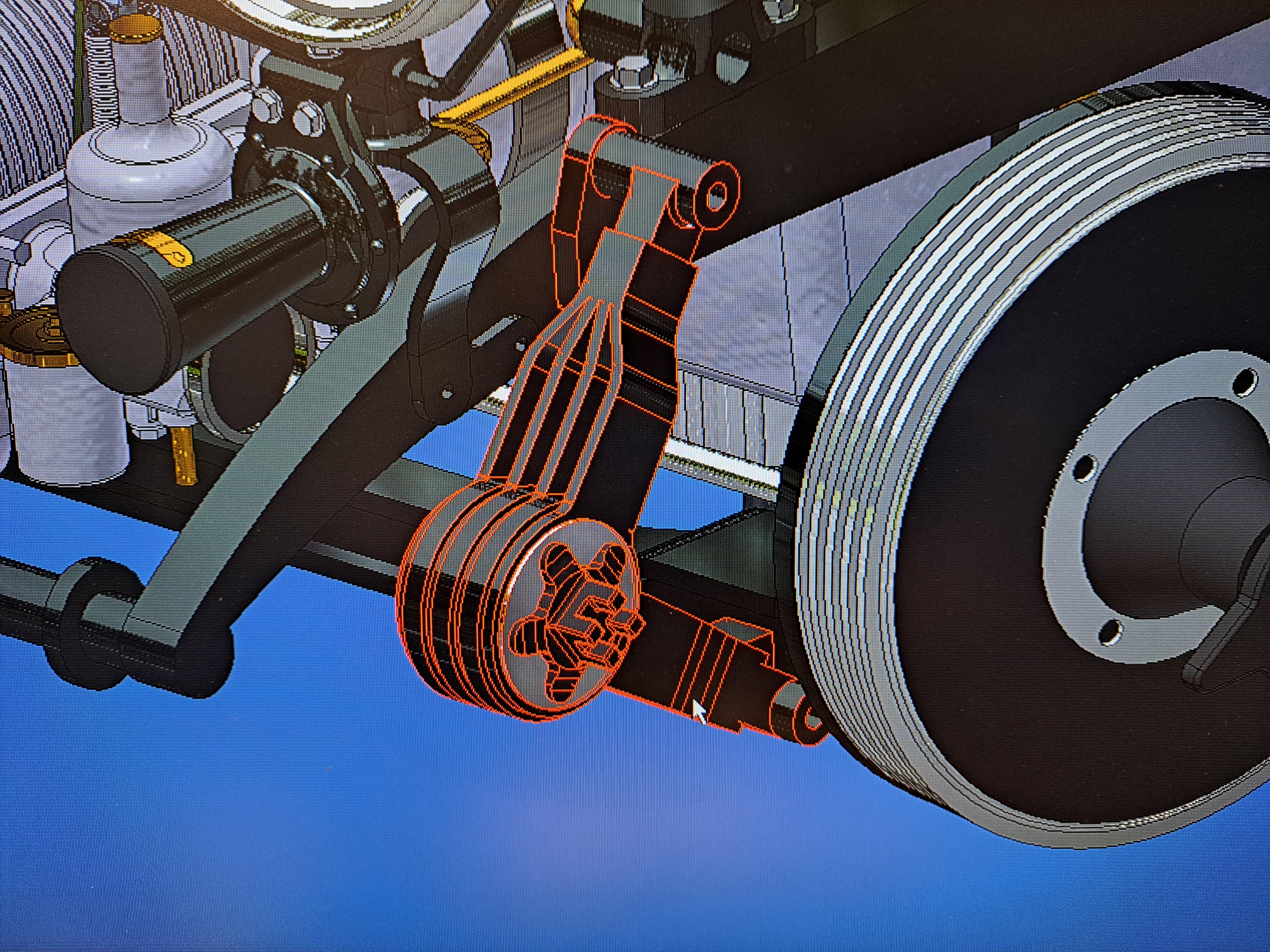
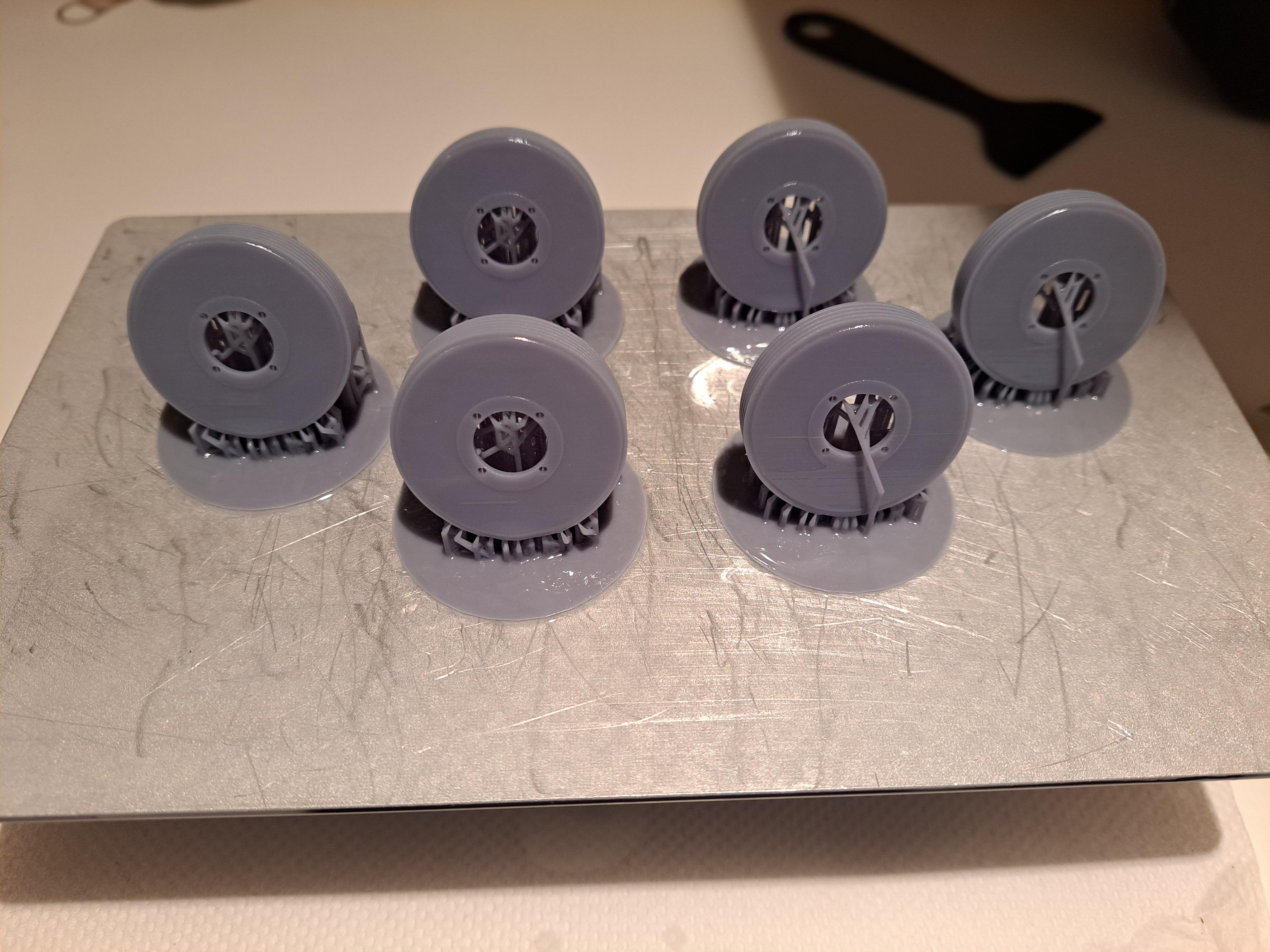
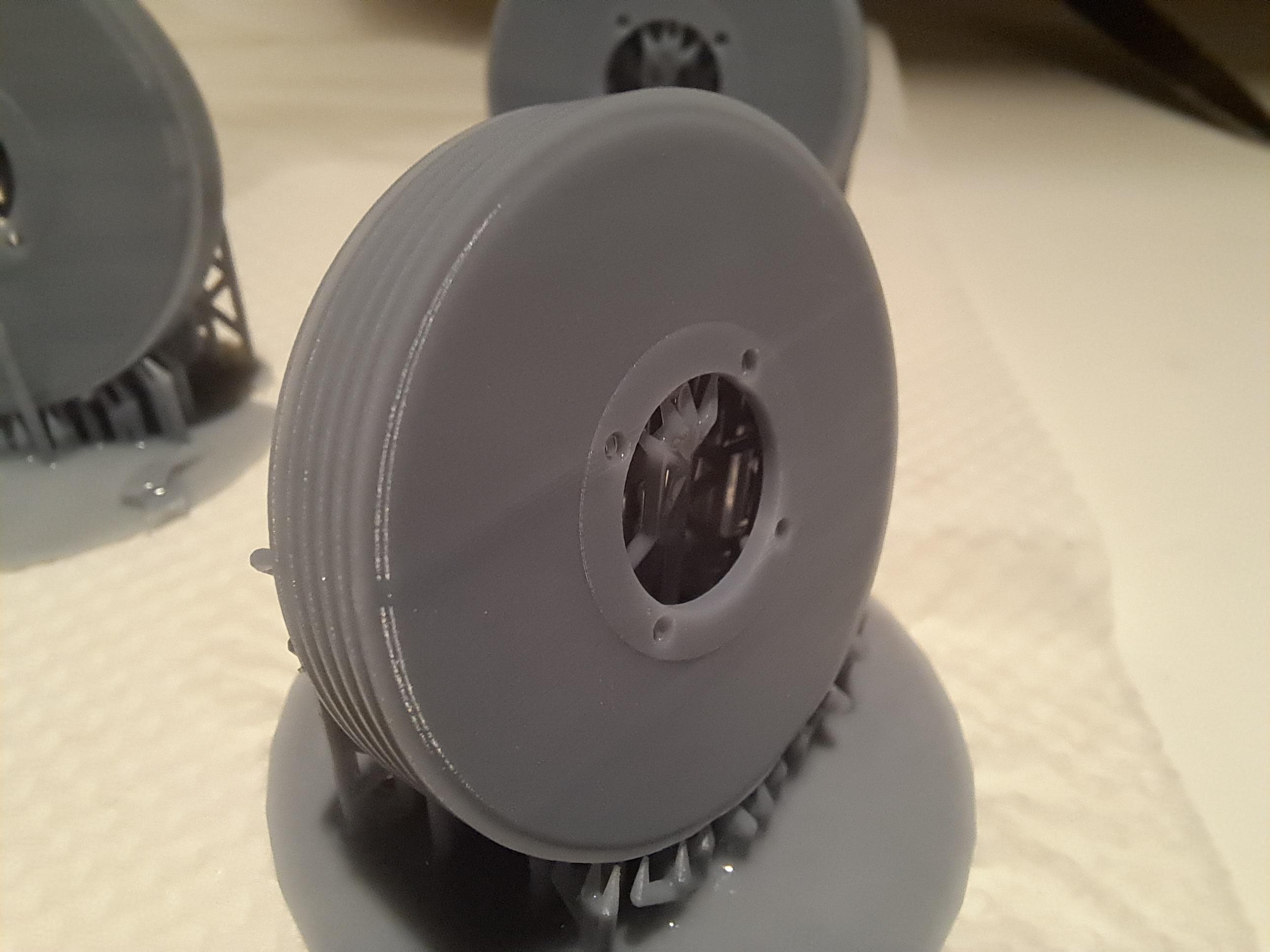
When I started this project, one of my goals was to have working brakes. To achieve this, I needed working brake segments. So I drew them up and printed them with the only printer I had at the time (a filament printer). So I had my brake segments which eventually gave me working brakes. The thing is, I now have a resin printer. Sooo, me being me, I had to redo them. Here are a few pictures. First, here's what the kit proposes These are the segments I printed first This is what I really wanted And this is what I now have. Still need to make the return spring. it's really nice to be able to do praticaly any parts at will!!
-
Thank you Bugatti fan, I'm very happy with the result so far. Not sure I agree with you on the 'comming to completion' part. There is still many months worth of work to do. Here a quick list of what is to be done. 1 finish wiring the head lights 2 do wire wheels 3 radiator 4 bonnet 5 redo all brake segments and drums with resin print 6 cover body with material, body doors, trims, floor, dashboard... 7 foldable roof 8 body stand 9 display case with interior lighting 10 eletrical box with battery holder and switchs 11 perhaps a second half body so the frame details can be seen but still have a body on the model(not sure about thin one) I guess I'll know it when enough us enough
-
Thanks Big John, It's the revell chrome. The pens work great but for small areas only and touch ups.
-
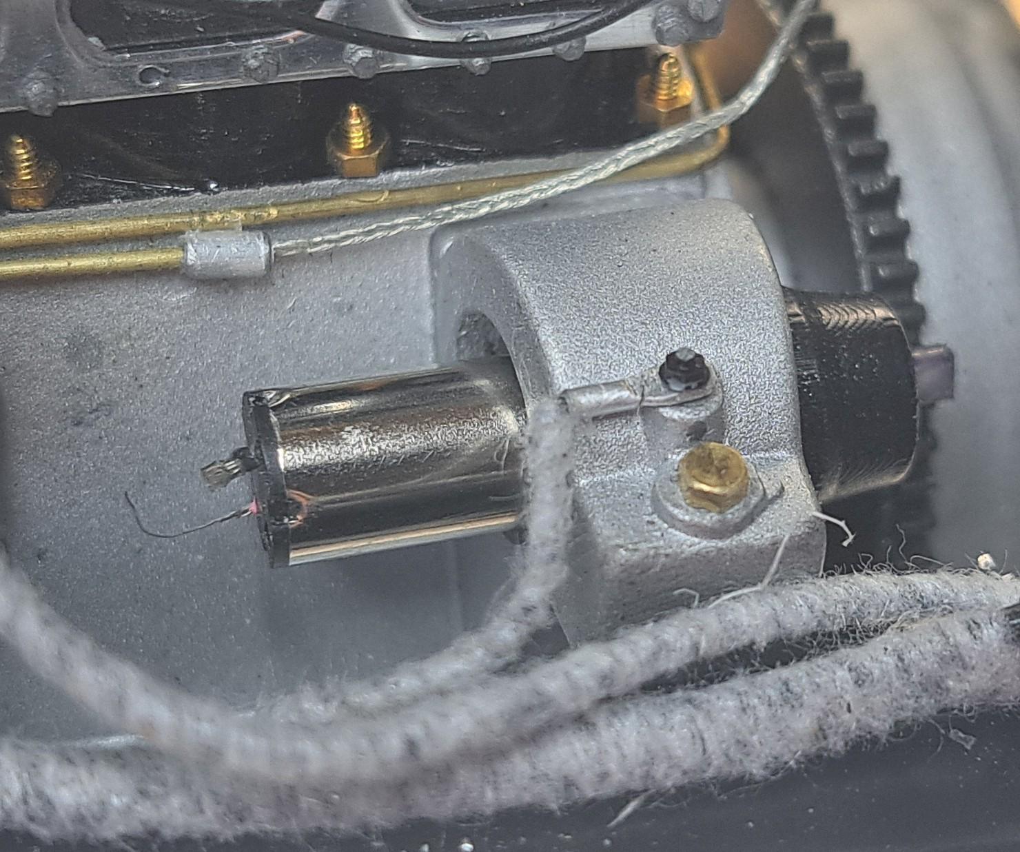
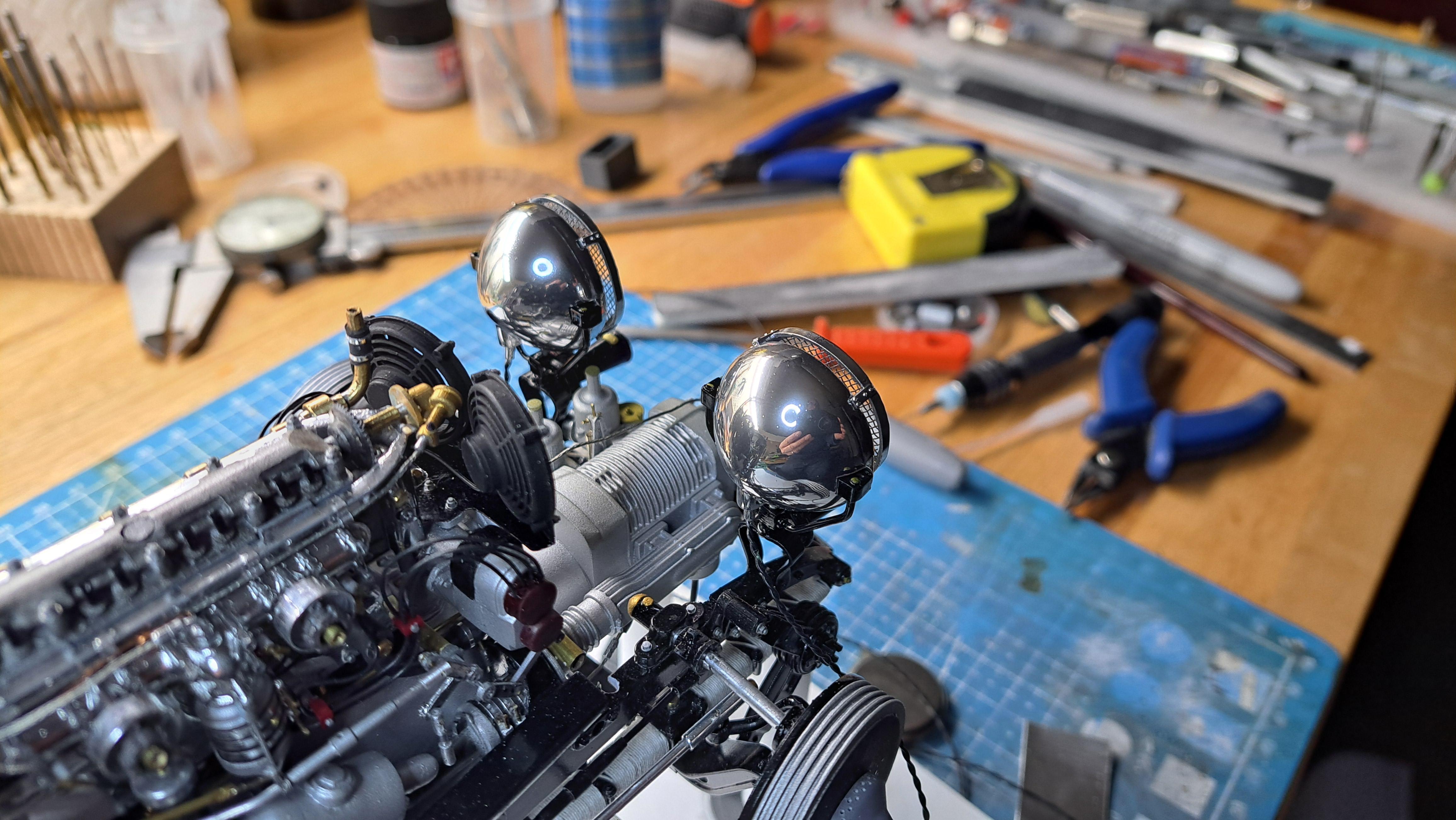
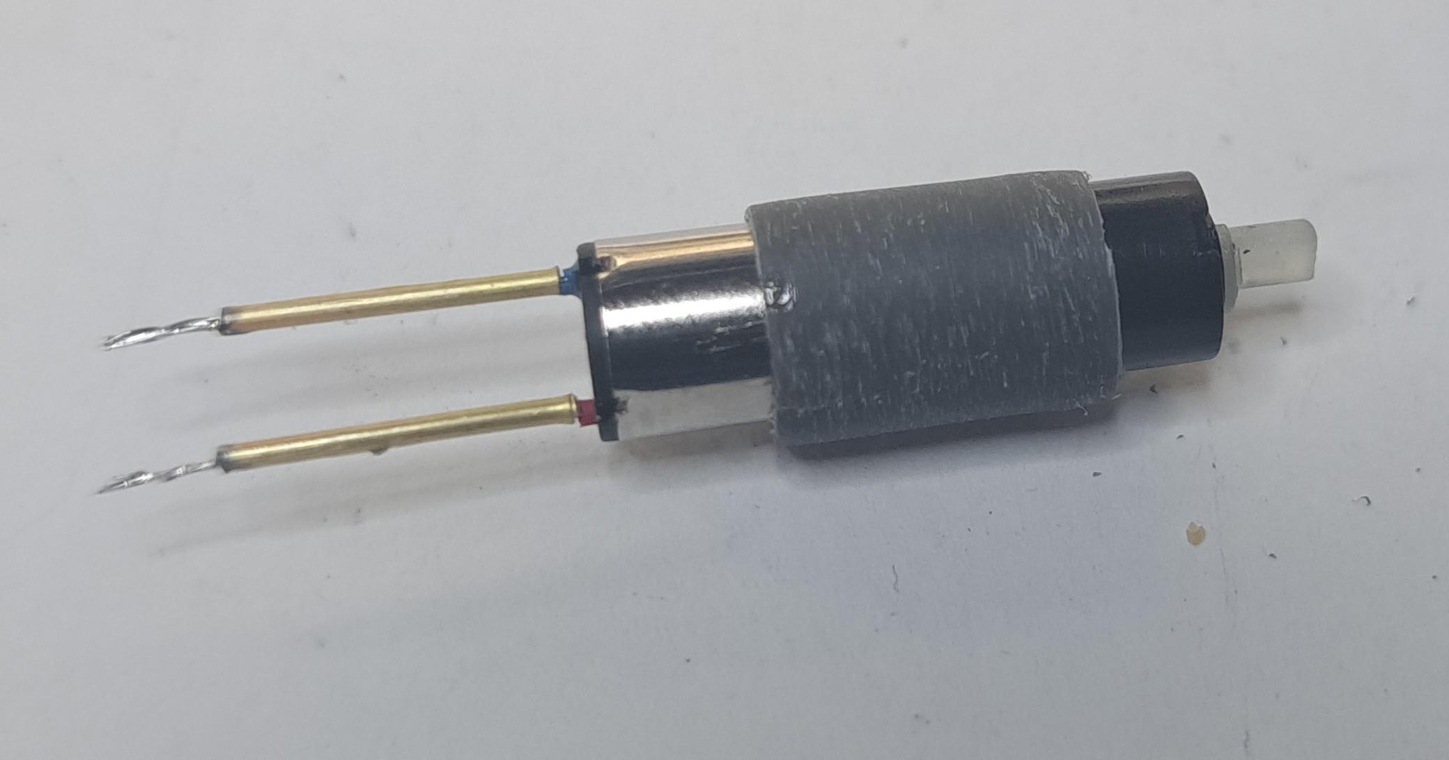
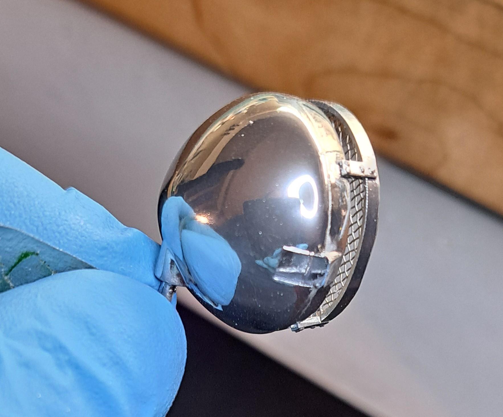
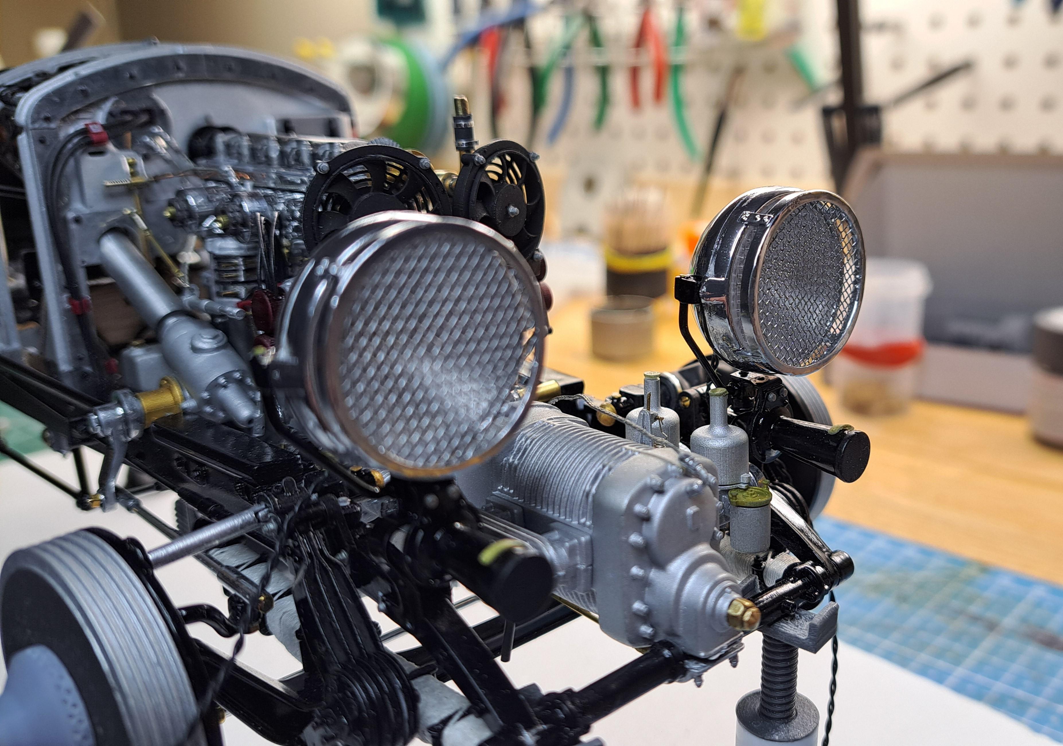
As mentionned earlier, I had a set back with the gearmotor that is supposed to run the drive train. While connecting the wires to the motor, the leads broke from the motor too close to the end plate to be repaireble. Fortunately, when I ordered the gearmotor, I ordered 2. One high ratio ( the one that broke) and one slightly lower ratio. So I very carefully removed the rear housing covering the back end of the motor and the spur gear and was then able to remove the broken gearmotor. I then redid the terminals in a more sturdy way on the new motor. I had to reprint a new rear housing and spur gear and after a few hours of coaxing, was able to refit the new motor and complet the wiring. 20231230_163606.mp4 I also wired the faux battery complete with proper battery terminals. I then set out to assemble and dry fit the newly chromed head lights. Very very happy with the result !!
-
Thanks Bugatti fan, I'm very satisfied with the grills. As for the wheels, having done the Alfa romeo wheels last year, I know to well how tedious it can be. I just need to give myself a swift kick in the behind and get on with it. I had a moderate set back yesterday with the gearmotor that drives the model's engine and drive train... more on that later...
-
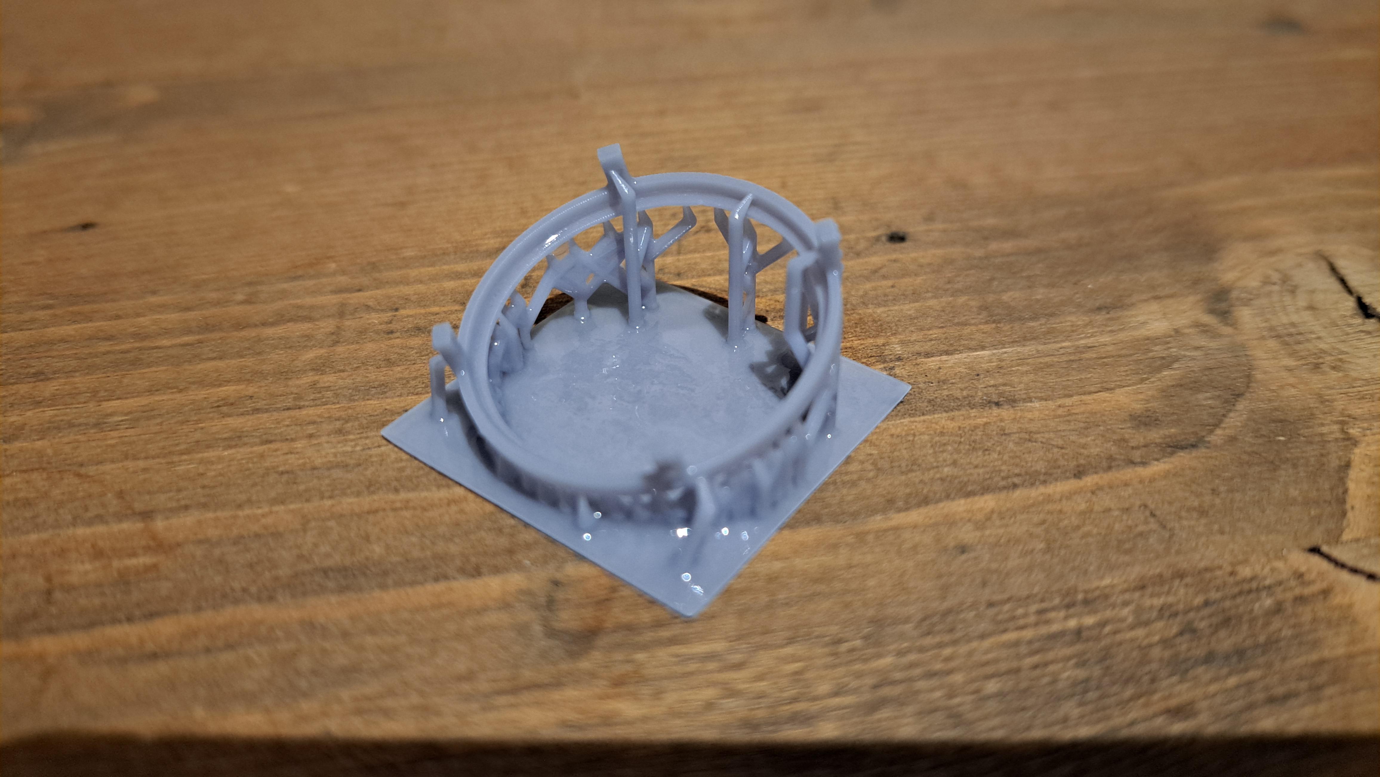
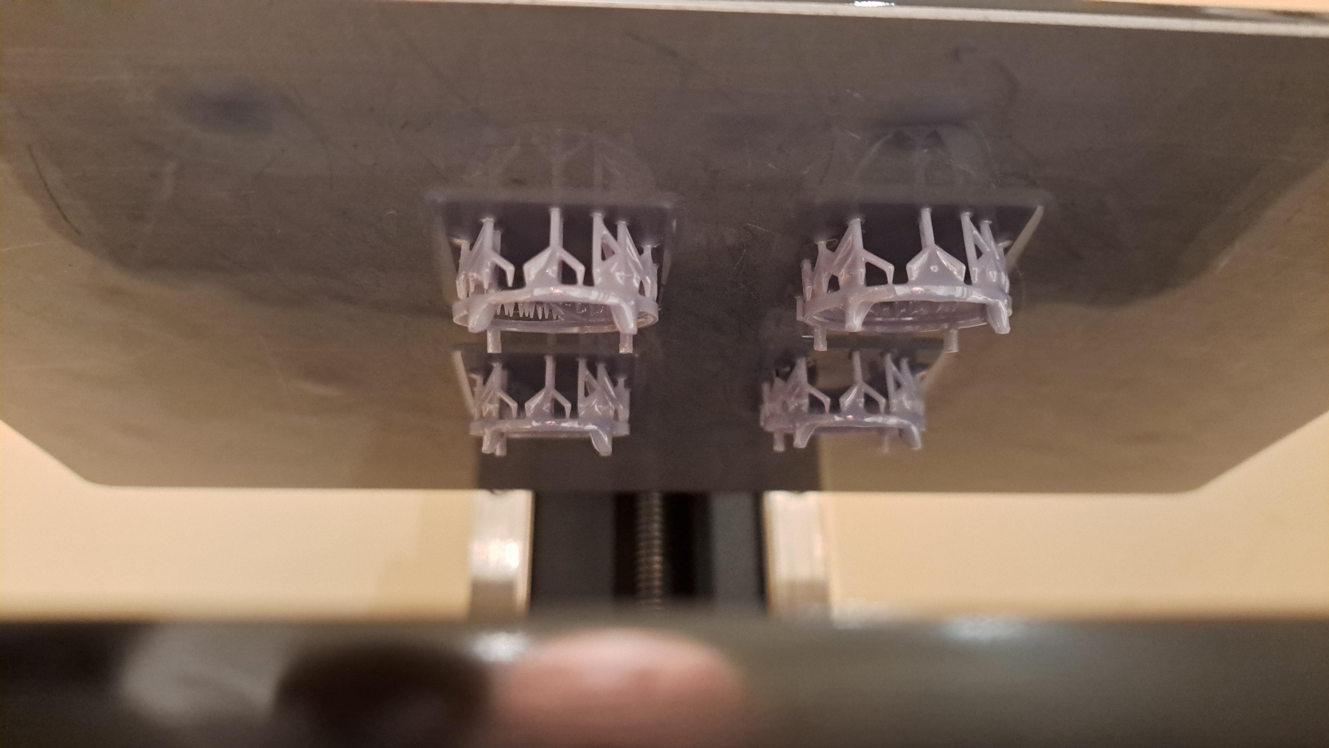
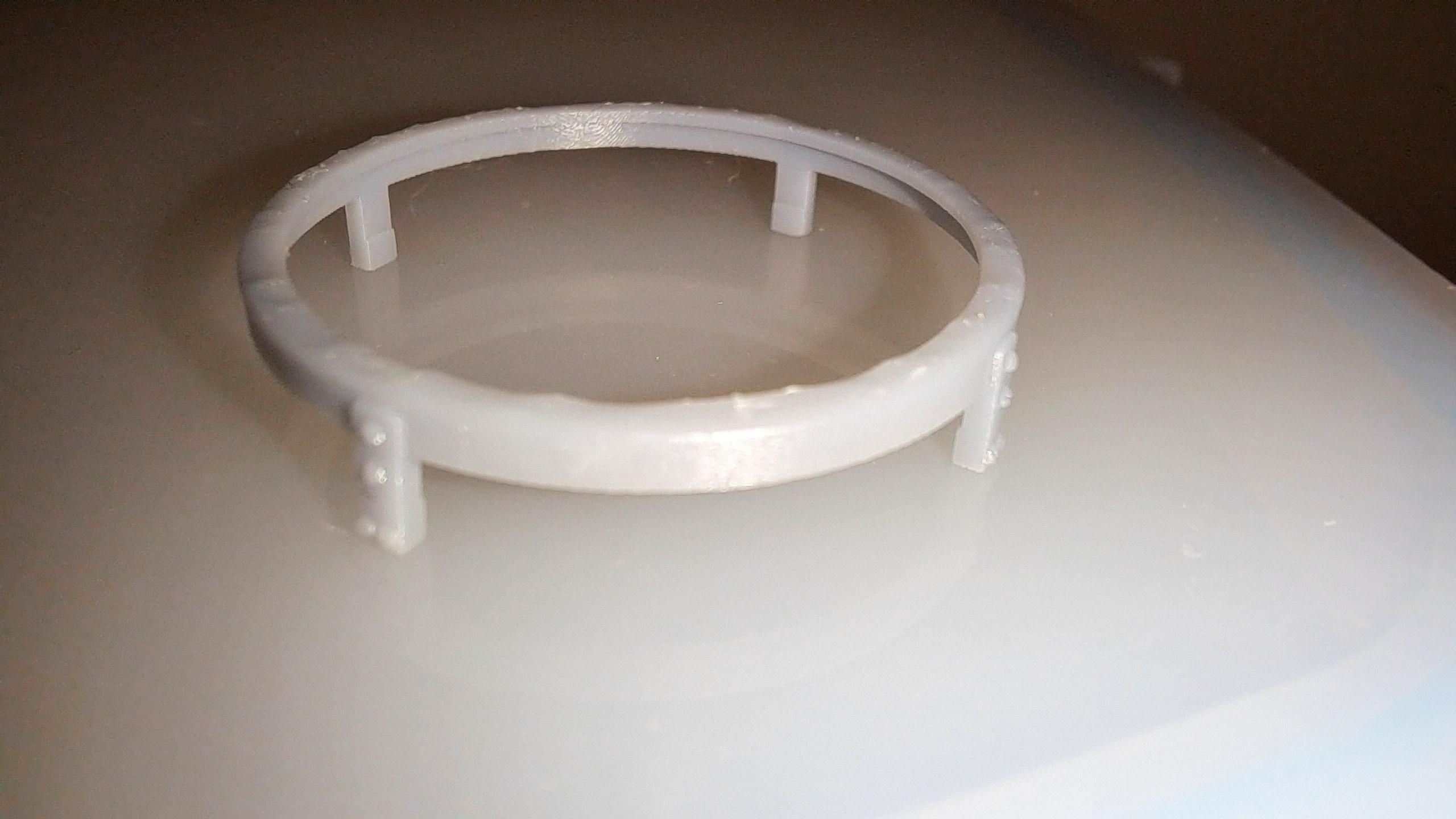
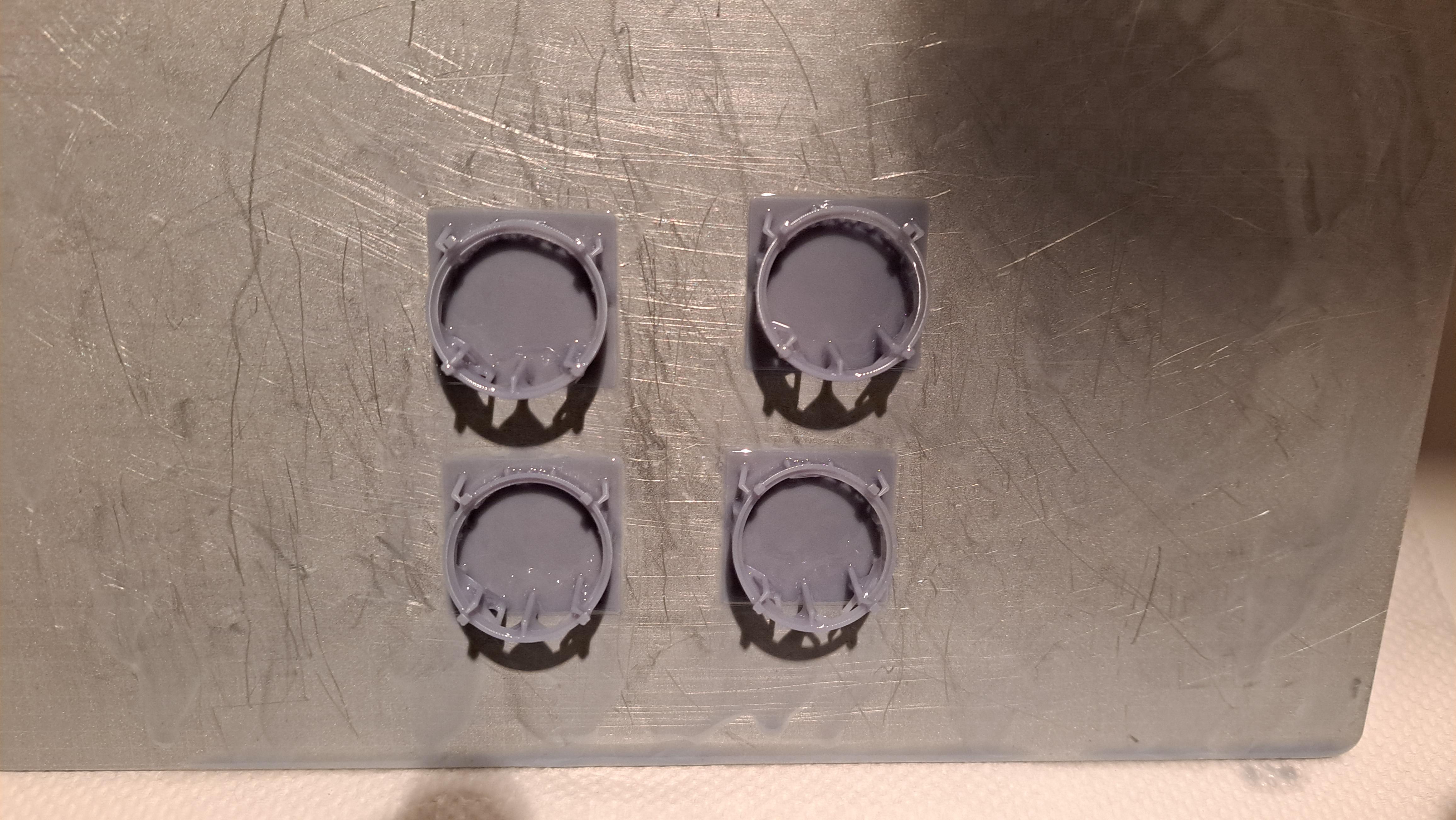
For those of you who are unfamiliar with the 3d resin printing process like I was, I thought it could be interesting to show the different steps requiered to print a part . 1- decide what to print. In this exemple, I wanted to improve the head light protection grill from this To this 2- 3d model the part 3- load the model in a slicer application. A slicer will literally slice the part in a multitude of layers. The number of layers depent on 2 things, the height of each layer, in this case it's 50 microns (.05mm) and the total height of the print. The taller the print, the more layers will be requiered and the longer the print will take. That's what fun with this process, the printing time is not dictated by the surface area being printed so a single small part of say 3mm height and 10mm square area will take as much time as 'X' of the same part as long as they fit on the printing plate. Now, this is where the game is won or lost. You have to give the proper orientation to the part so as to not have too much surface area being printed on each layer while taking care of the esthetics. You want to avoid supporting the part on visible surfaces because the anchor point will show a bit (or alot depending on their size and number). In this case, I wasn't able to avoid this but fixed the problem later on. Once oriented, you then add supports. The idea is to support the part at strategic point as it's being printed, avoiding overhangs. 20231229_071358.mp4 4- load in printer and print 5- wash part in washing station. I use a water wash resin so cleaning is done with water. Most resin will requier cleaning with alcool 6- remove part from support structure by diping in boulingrin water for 2 to 3 seconds. This is not always necessary but will make separation alot easier. Before boiling After 2 sec dip 7- Cure in curing station. Most small parts will cure in 2 minutes. The longest I cured à part was 5 minutes. (The washing and curing uses the same machine, at least mine does) After curing ( notice the bumpy top surface) 8- part finishing. Here you have to remove any anchor points that will be visible with either a blade, snippers or sand paper. I this case, not being able to support the part on a non visible surface ( I tried 5 different orientation but only one worked, I'm sure that someone with more experience could have achieved this), I printed a sanding tool since this part is very fragile. Sanding tool And after sanding All that is left to do is to install the wire mesh and chrome. So that's it, hope you enjoyed this!!
-
Yes, I think the scale is ok.
-
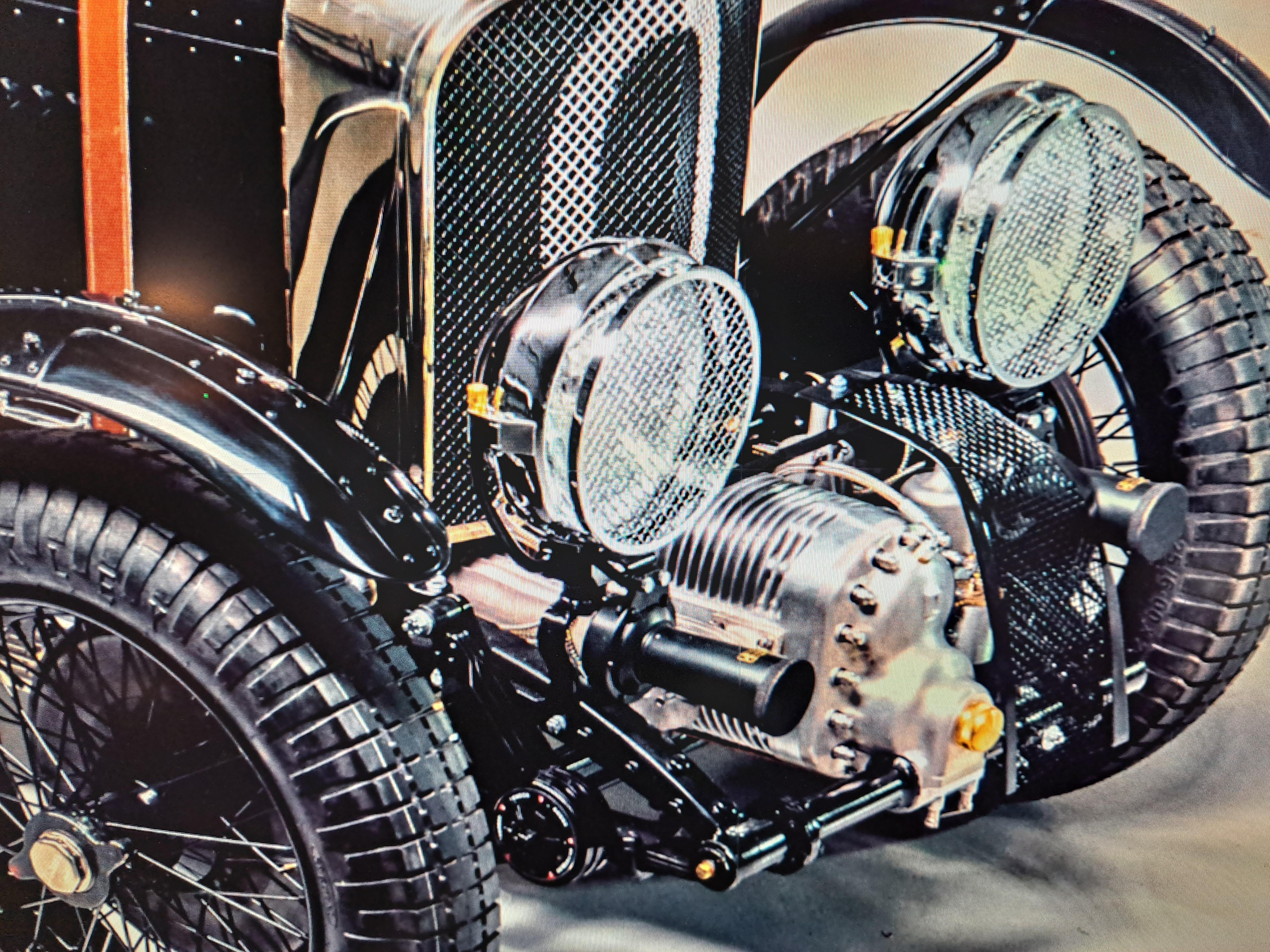
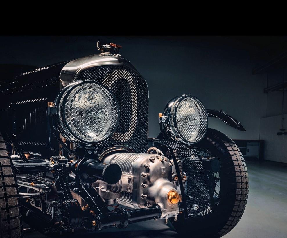
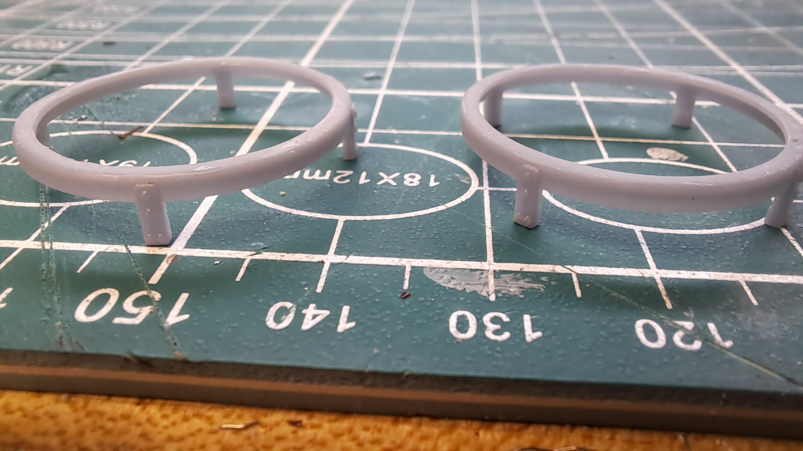
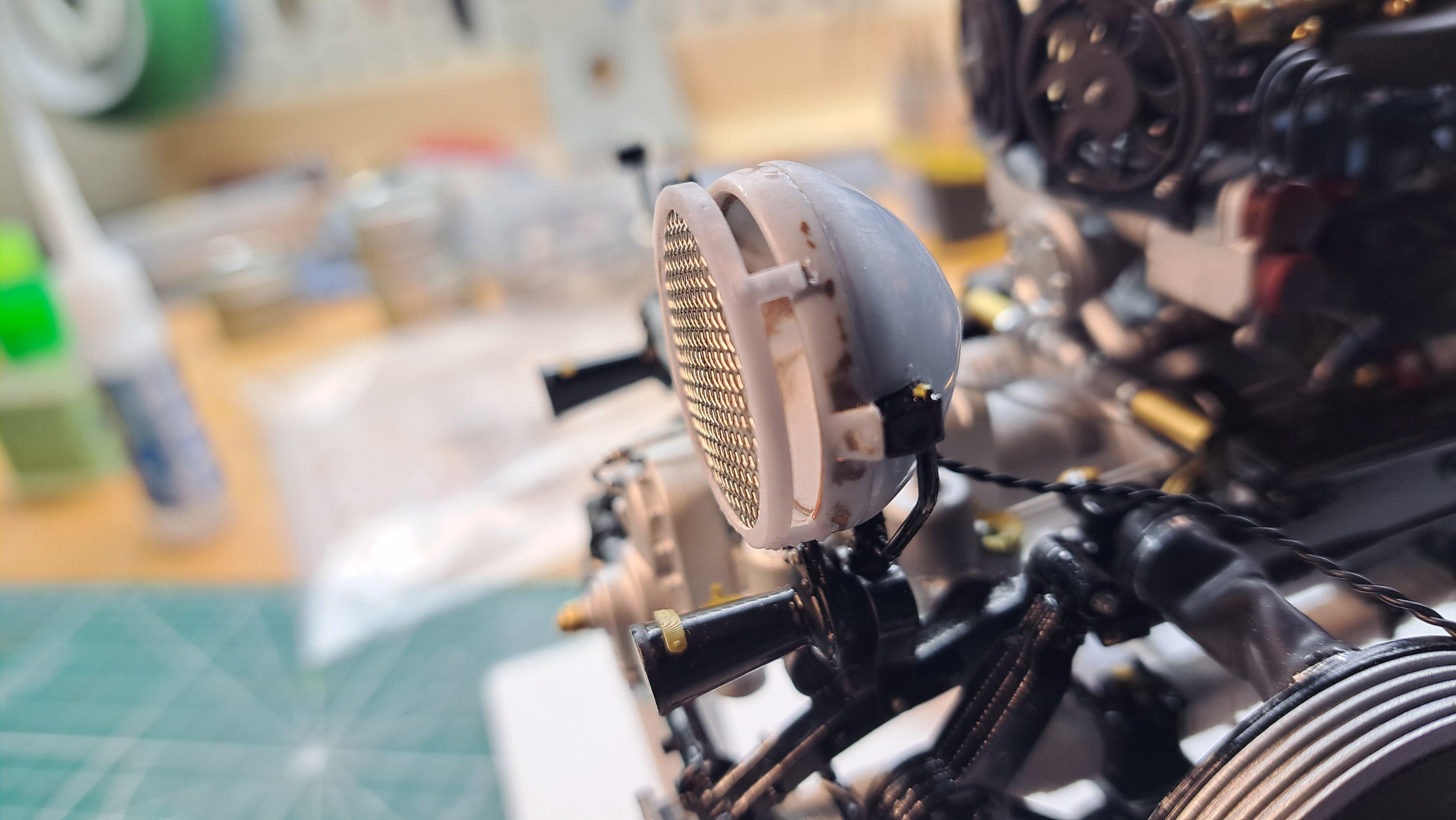
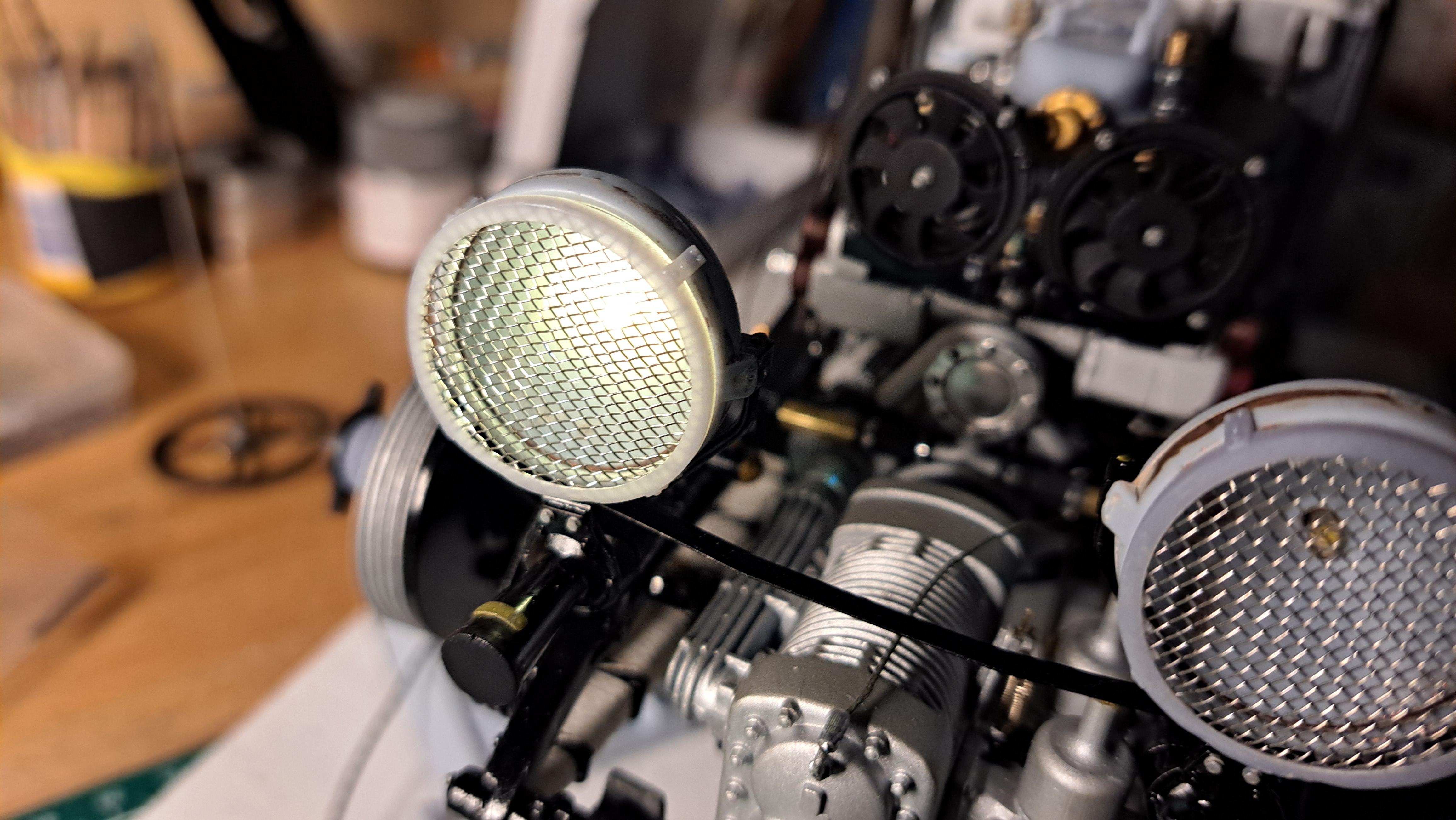
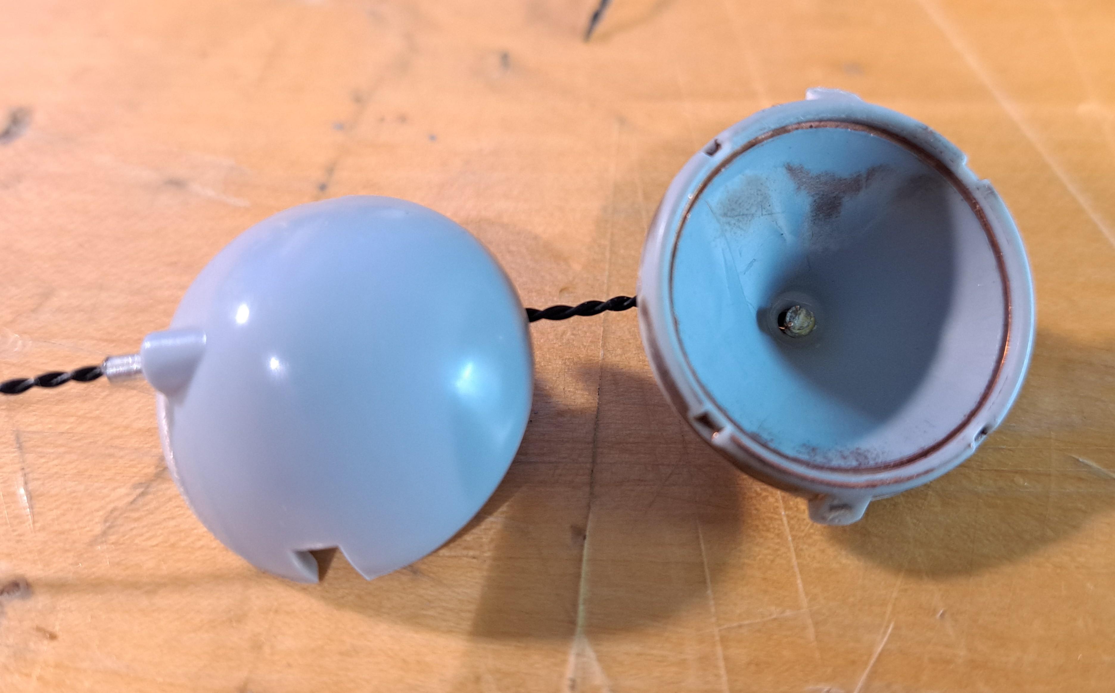
Saw horses would effectively be more period correct but since I'm reproducing a blower built in 2019 and they put the bodies on more modern trolleys, I will probably stick with this. And I must admit that I like the mecanical aspect of the wheeled trolley as opposed to a simpler wooden saw horse. That being said, I might very well change my mind when the time comes, would't be a first!! I wired the head lights today and they work. Just need to chrome them up. I also 3d modeled the grill rim as the one furnished in the kit is not really nice. I know that many modelers will cut away the center portion of the grill and add a real mesh. And I might end up doing just that but I'll try printing some more accurate rims first. I have a proper size wire mesh that has a .04" aperture that gives me about 20 squares which is about right and a .005" wire that scaled up is 1/16", also correct. Wired head lights Test fitted on car Lights on 3d modeled grill rims Real thing Proper sized mesh Kit's head light grill
-
Thanks absmiami! I keep pushing off the lacing of the wheels but I'll have to do them eventually. The hubs were resin printed but I printed the drums with my filament printer. I might try to reprint them in resin for better details. I might also reprint the brake segments for the same reason.
-
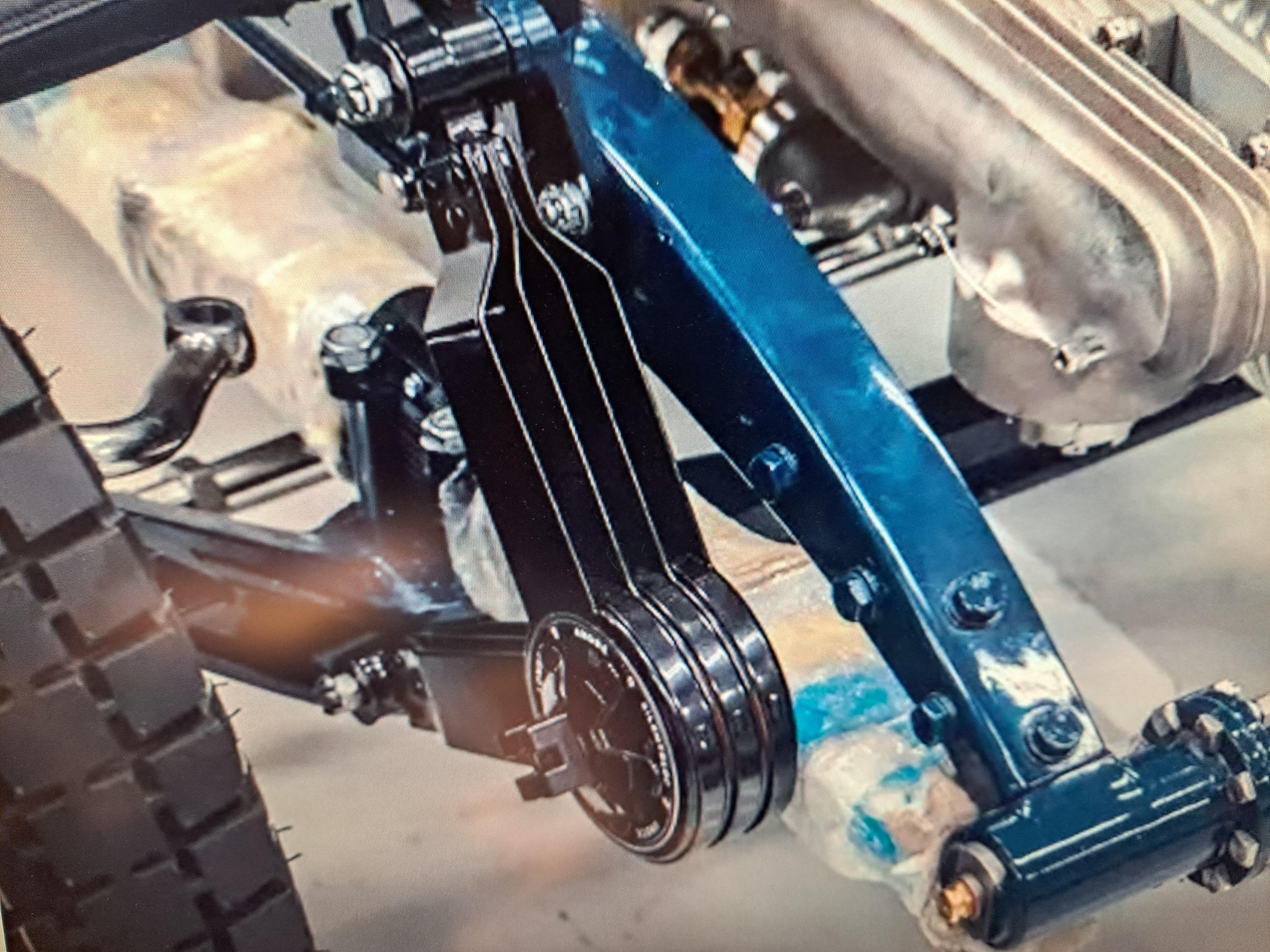
You can get a laser cutter for around 1500$ which is still quite expensive but I'm hopeful that, like with 3d printers, the prices will go down in years to come. As a side note, my very first encounter with 3d printing was back in 1995. I was designing an in line skate assembly machine for Bauer and they gave me a prototype wheel hub that had been 3d printed on a very big printer. The tech back then resembled todays resin printer in the manner that the part gradualy came out of a vat filled with a resin of some sort. But the major difference is that this big printed cost 1000000$ (yes, than many zeros) and the print quality was to 1995 standards. I can print the same part on my 500$ printer with a much better result. So yes, I am hopefull that laser cutters will be affordable. The shock absorber being done, my next task will be to run some micro gage wires from the head lights and gearmotor/starter all the way to the back of the car and eventually out of the still to be determined showcase and into a, also to be determined, electrical cabinet where there will be batteries and switchs to activate the head lights and the engine.
-
Finished the shock absorber, I think they turned out pretty good. Front shocks compared to the real thing Rear shocks
-
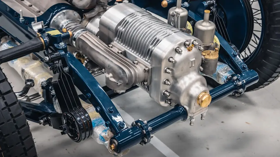
Ha but that's where it gets interesting Big John, my plan is to have a removable body that would be on it's own stand beside the car. That way I wouldn't lose any of the frame details. A bit like this. The completed body mounted on a stand and the completed frame on jack stands
-
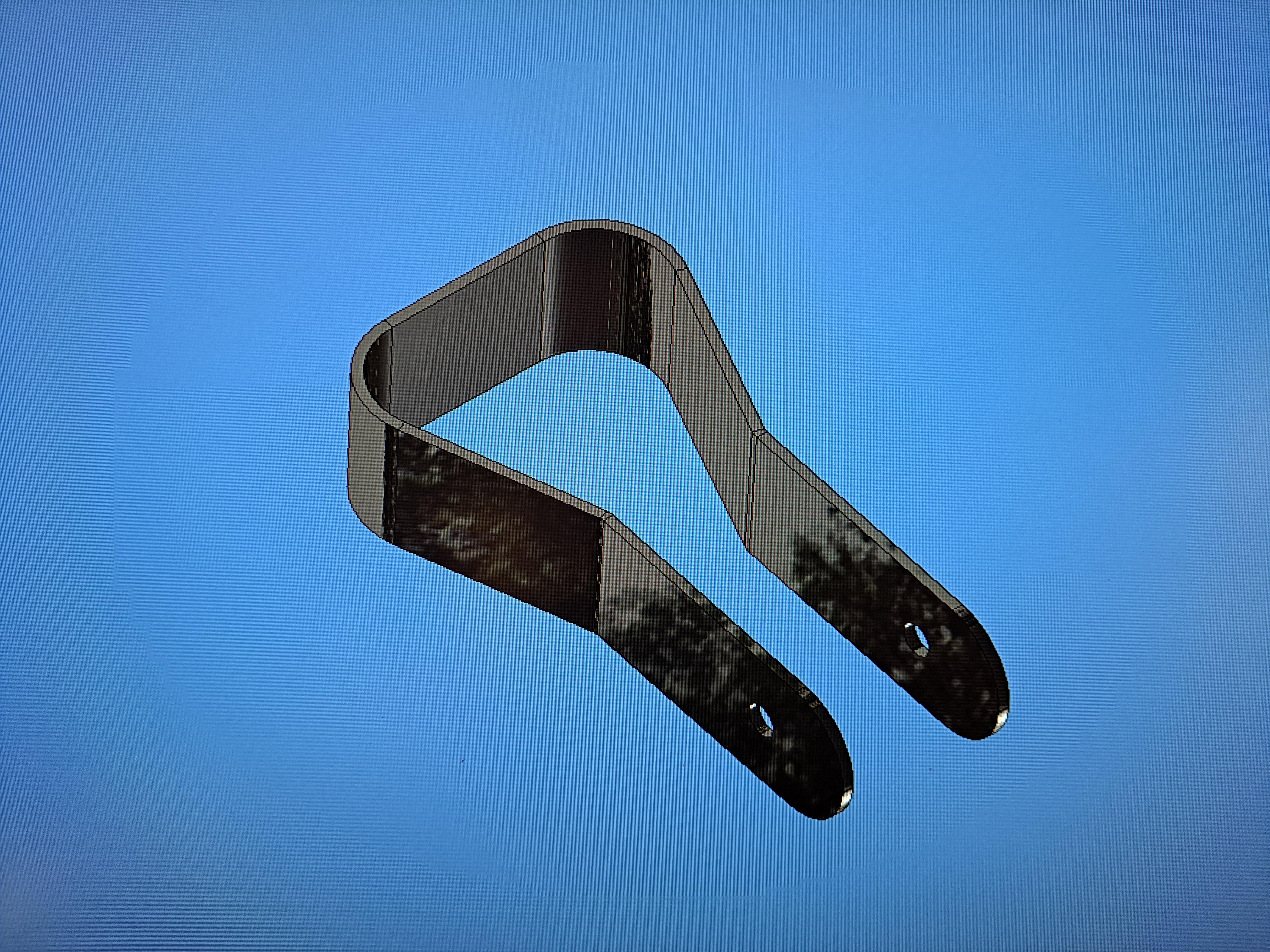
It would certainly be a way to do it but I would need to fabricate close to 30 separate plates, all identical. If I had a laser, it would be doable but I don't (yet!!). The prototype had .025" thick arms (.3" scaled up). I've reprinted the parts with. 015" thick arms (.18" scaled up). It looks a lot better but I think I can still improve it with better print supports and a bit more details.
-
Absmiami, I have 2 printers and both were gifts. The firts one I received for father's day is an Ender 3 filament printer, very easy to use but not all the precise. I mostly use it for jig and fixture. The second one I got for my 60th birthday last month is an Anicubic photon m5s resin printer. At 12k resolution, it's alot more precise but much more complicated to use. I still have alot to learn but I'm able to print some parts. Today I 3d modeled the front shocks. The kit's shock are very basic and if not installed at the very begining, they just don't fit. So I made mine from multiple pieces like the real ones. That way they can self adjust when I install them. The components My shock (top) vs the kit's shock (bottom) The real thing The 3d model Installed on the car, this is only a prototype. I have to figure out the best way to position the parts in the printer and how to support it in order to get a good print. That's what I find is the most challenging aspect of resin printing.
-
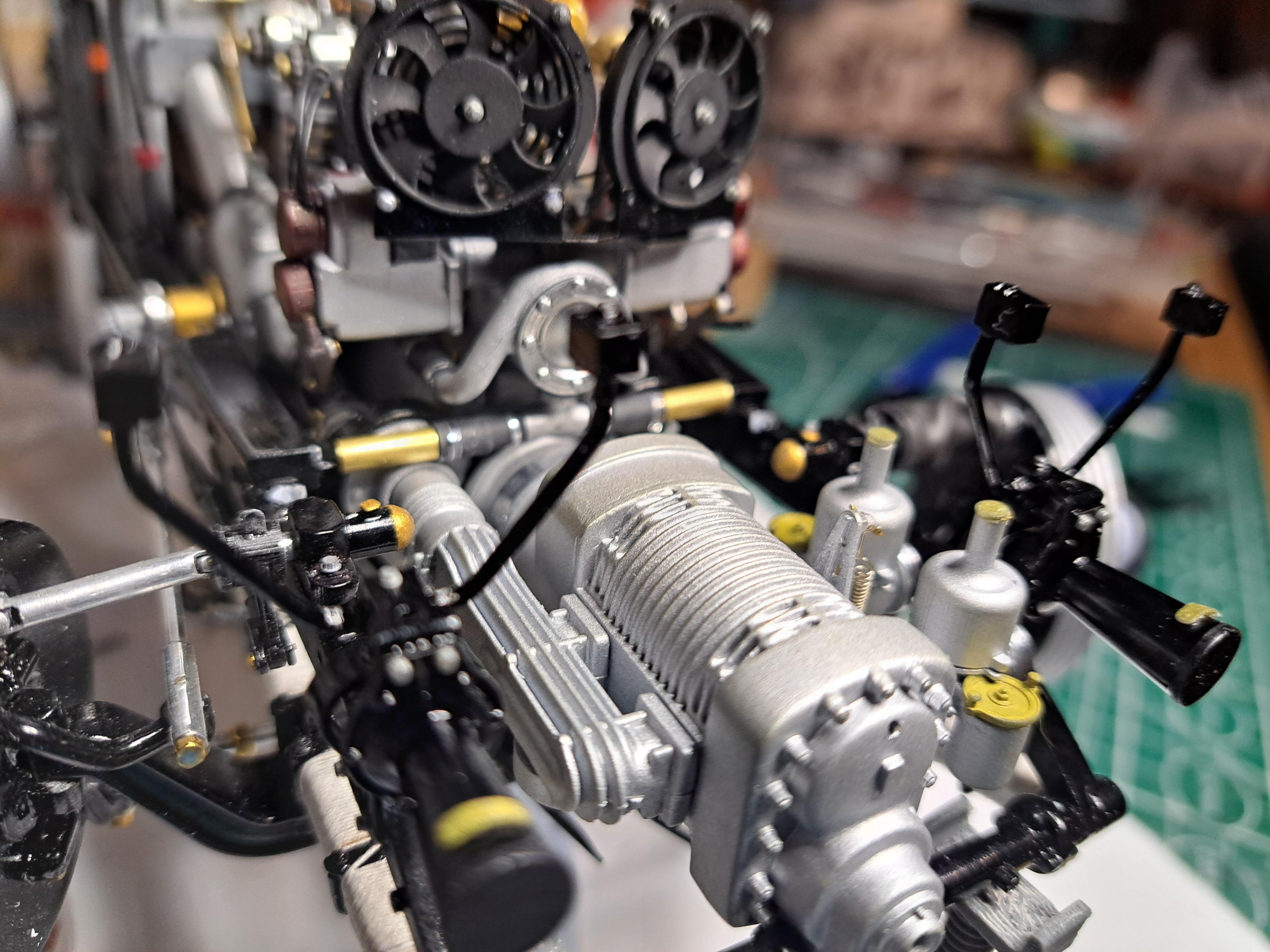
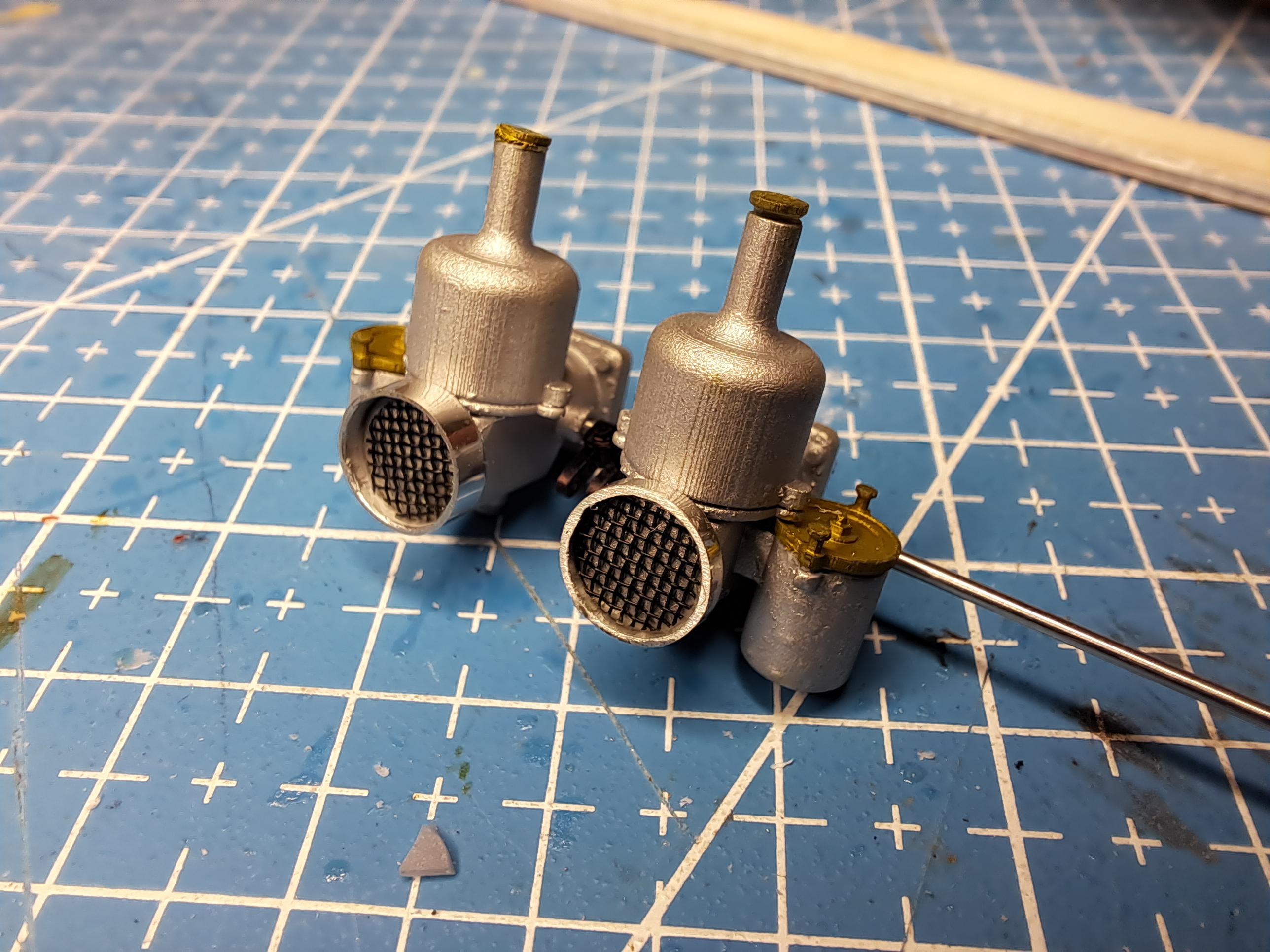
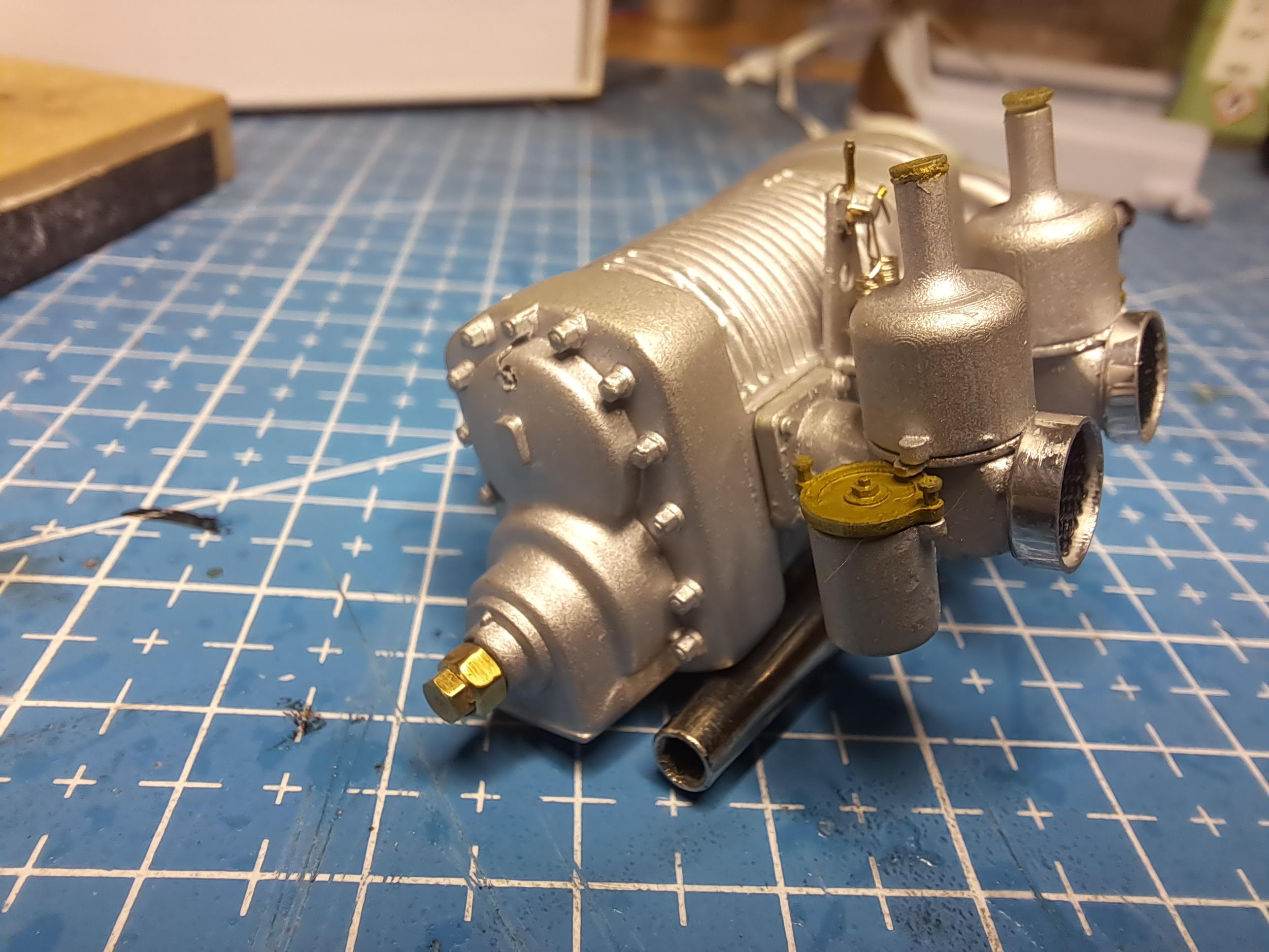
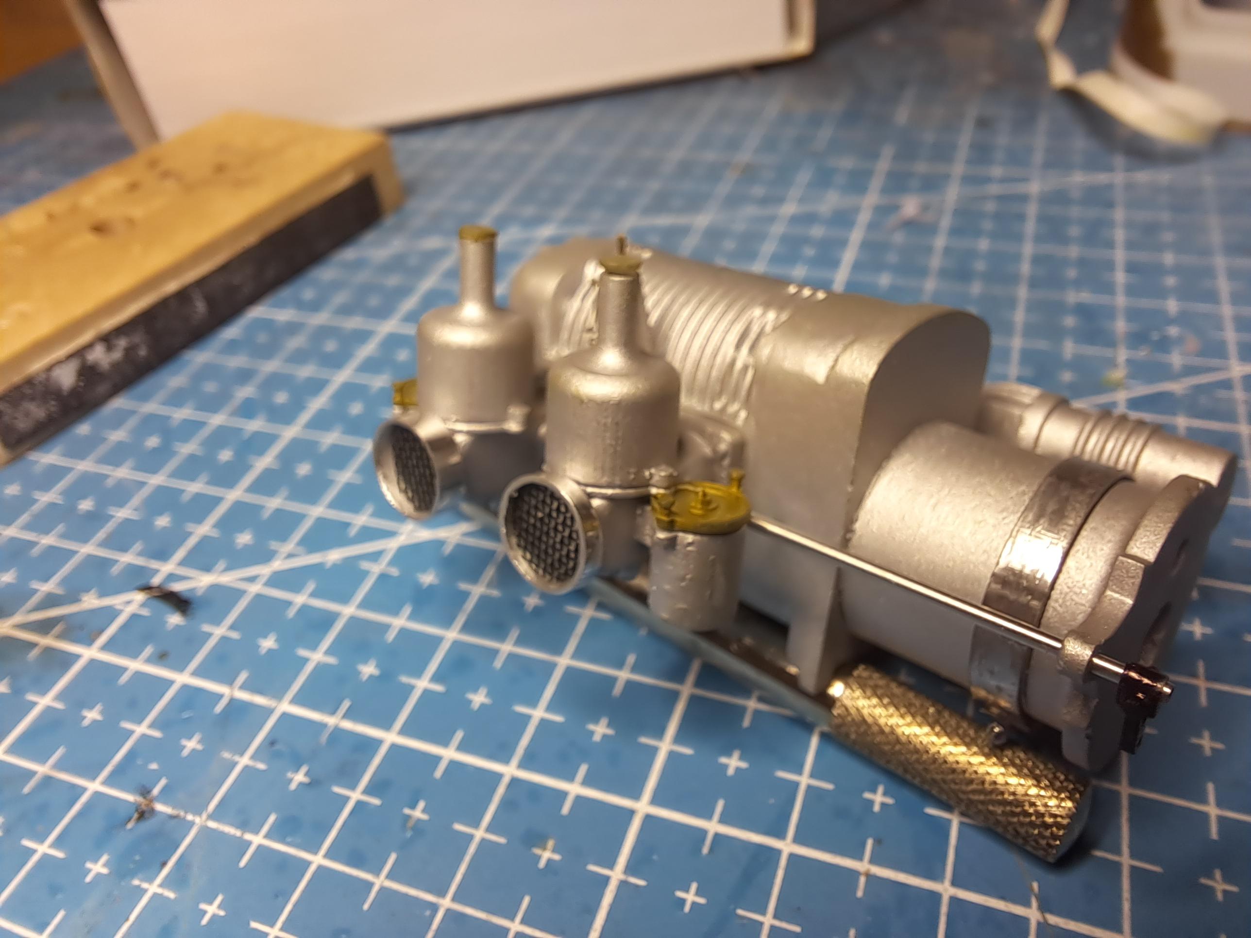
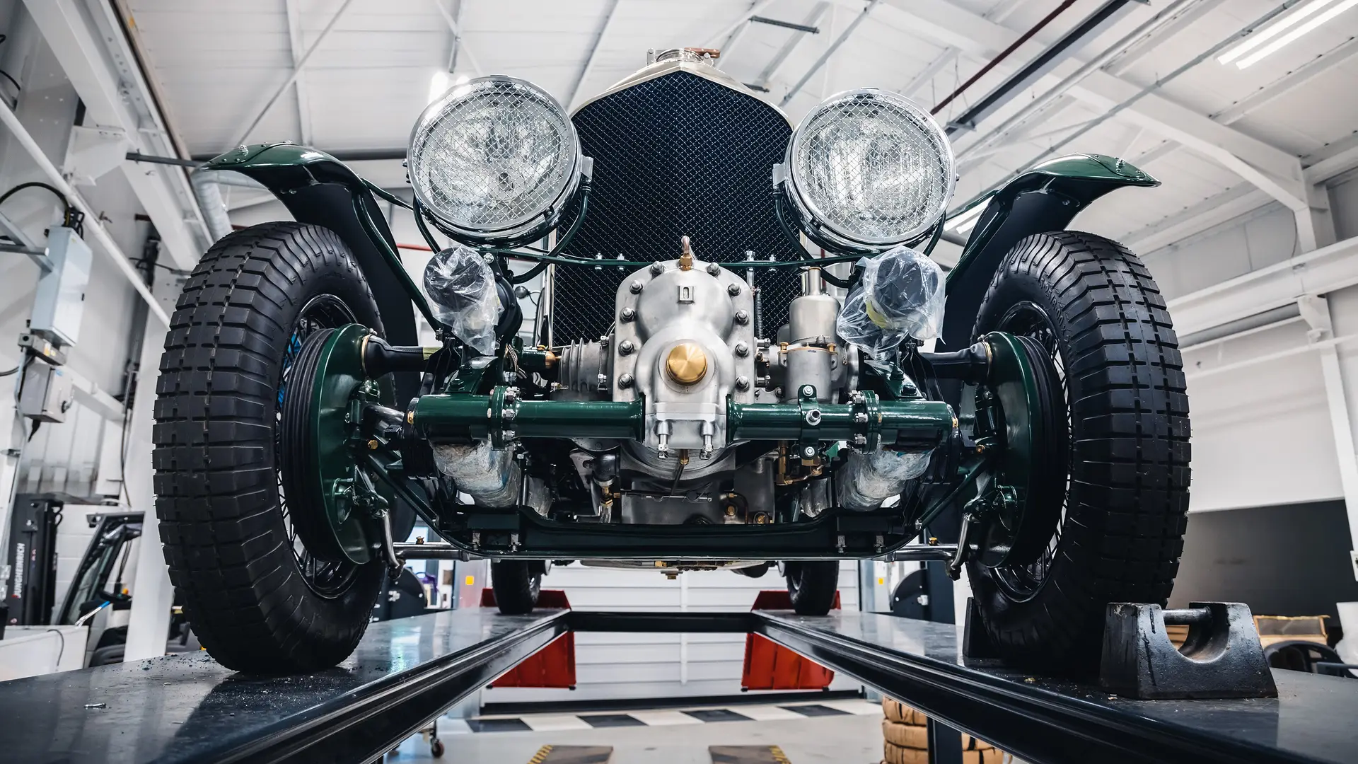
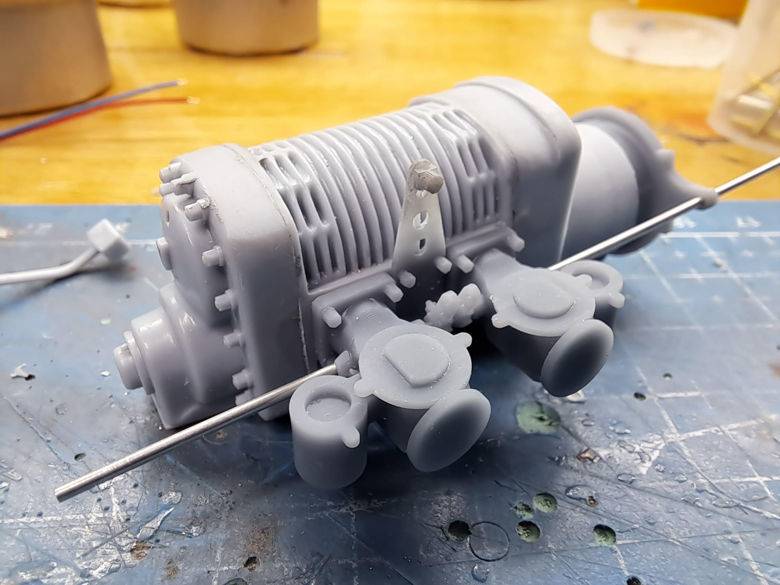
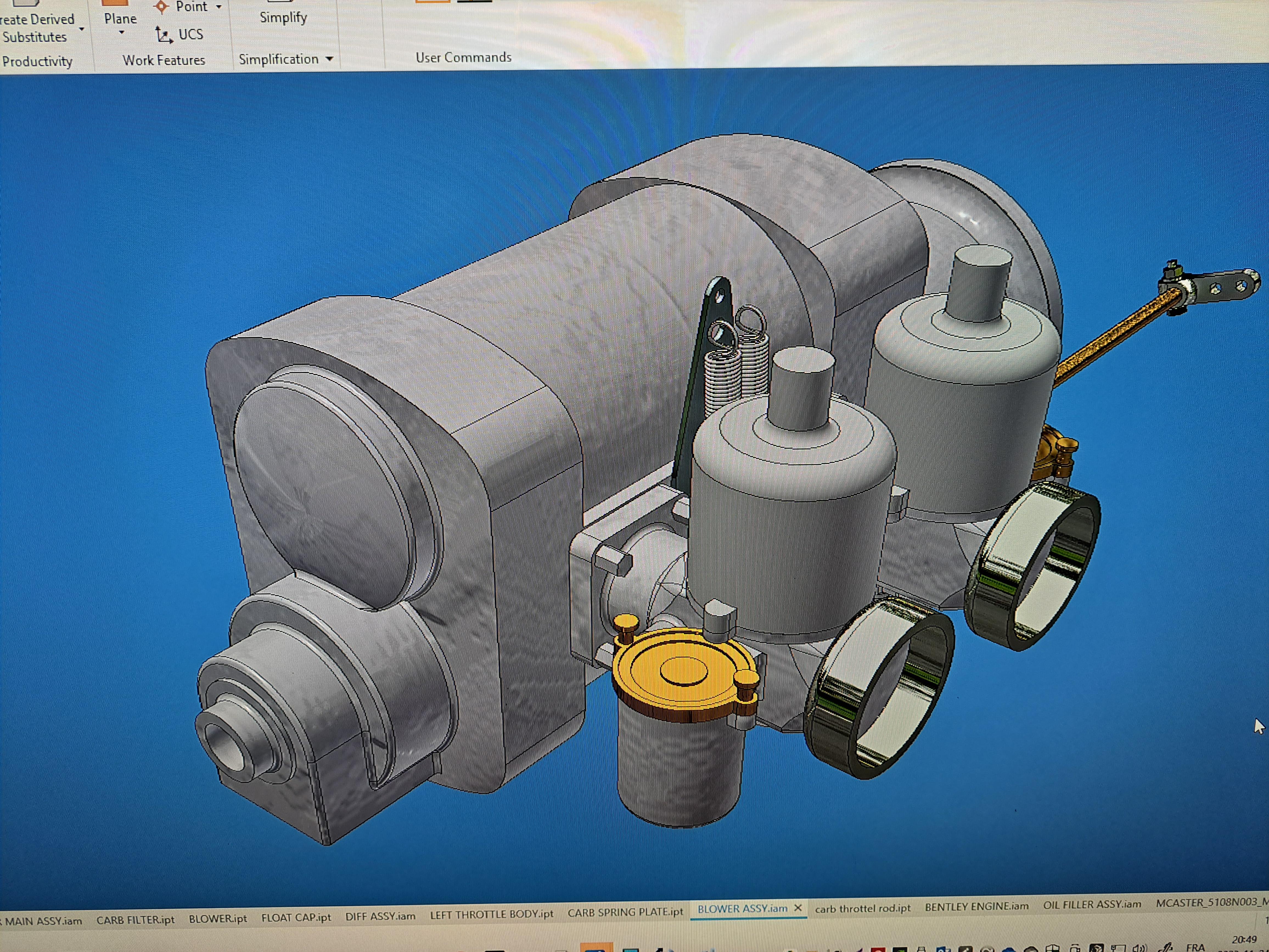
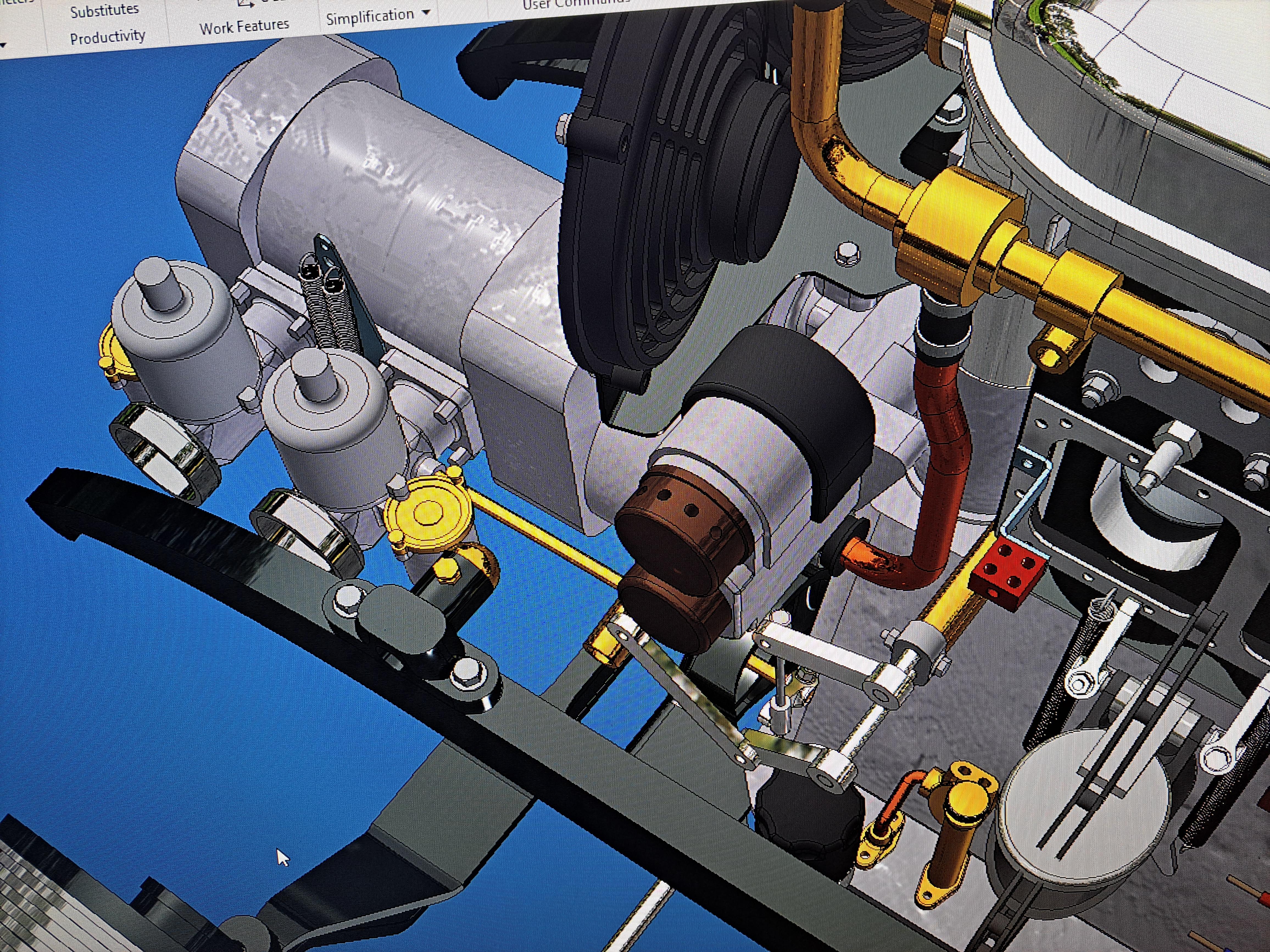
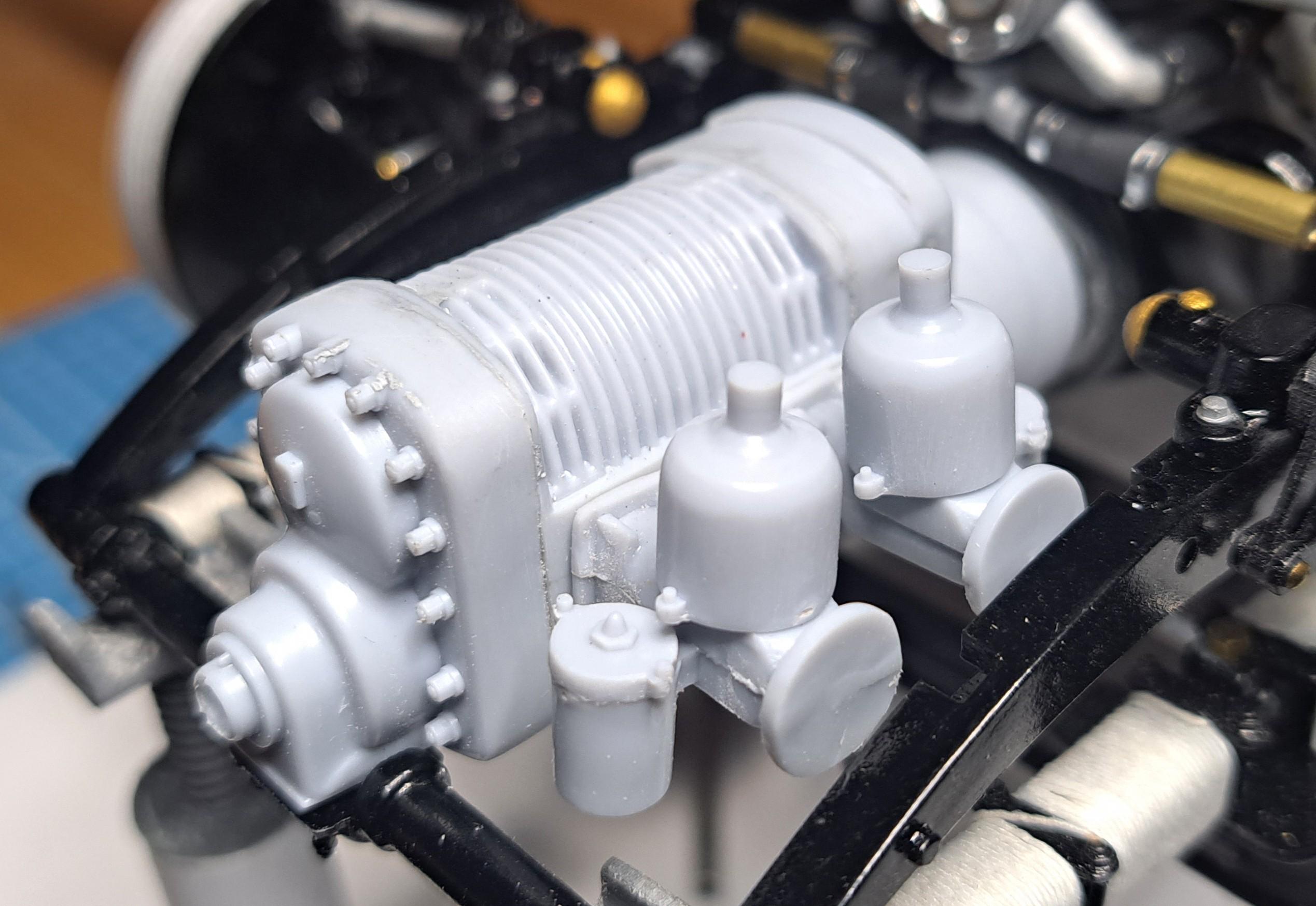
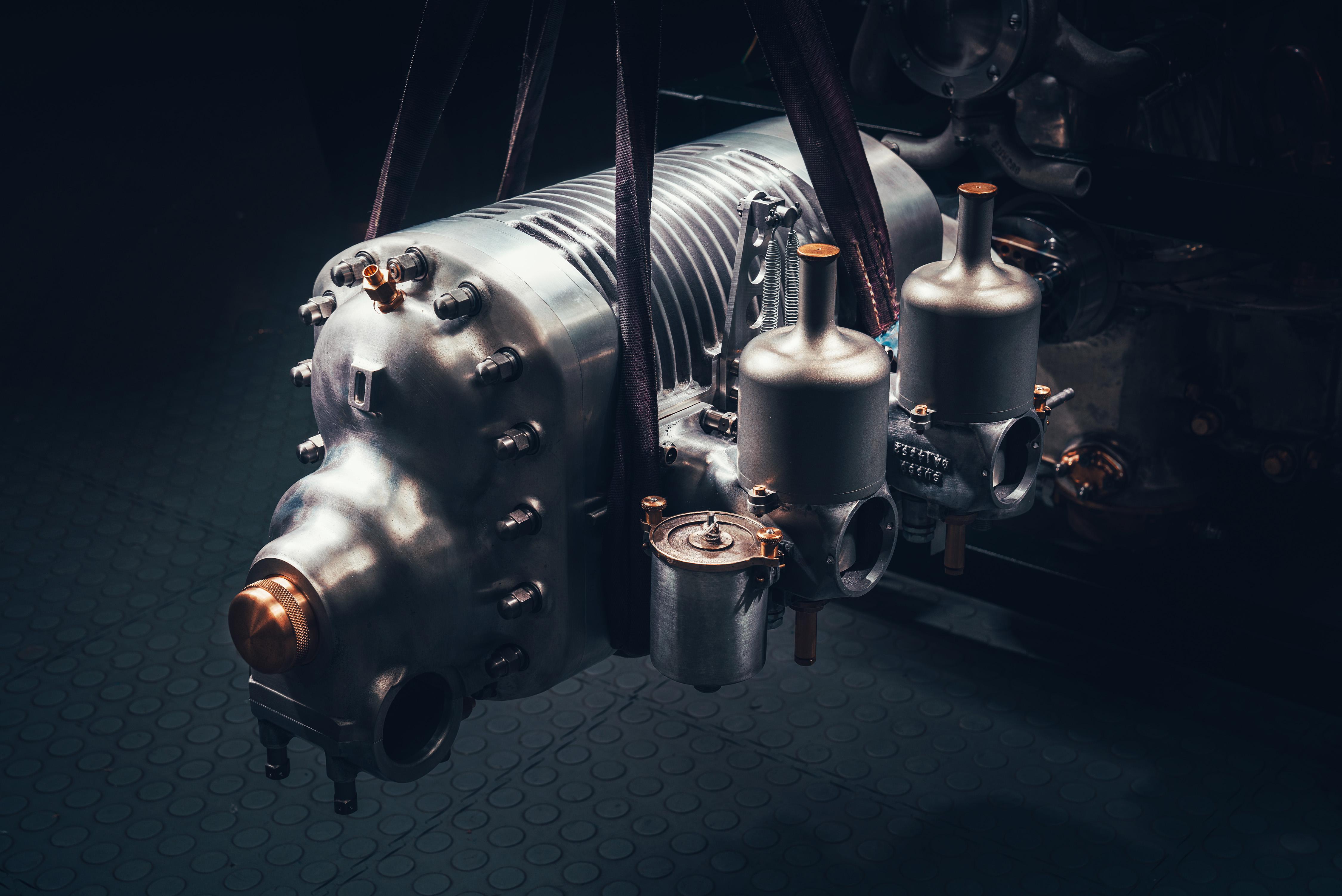
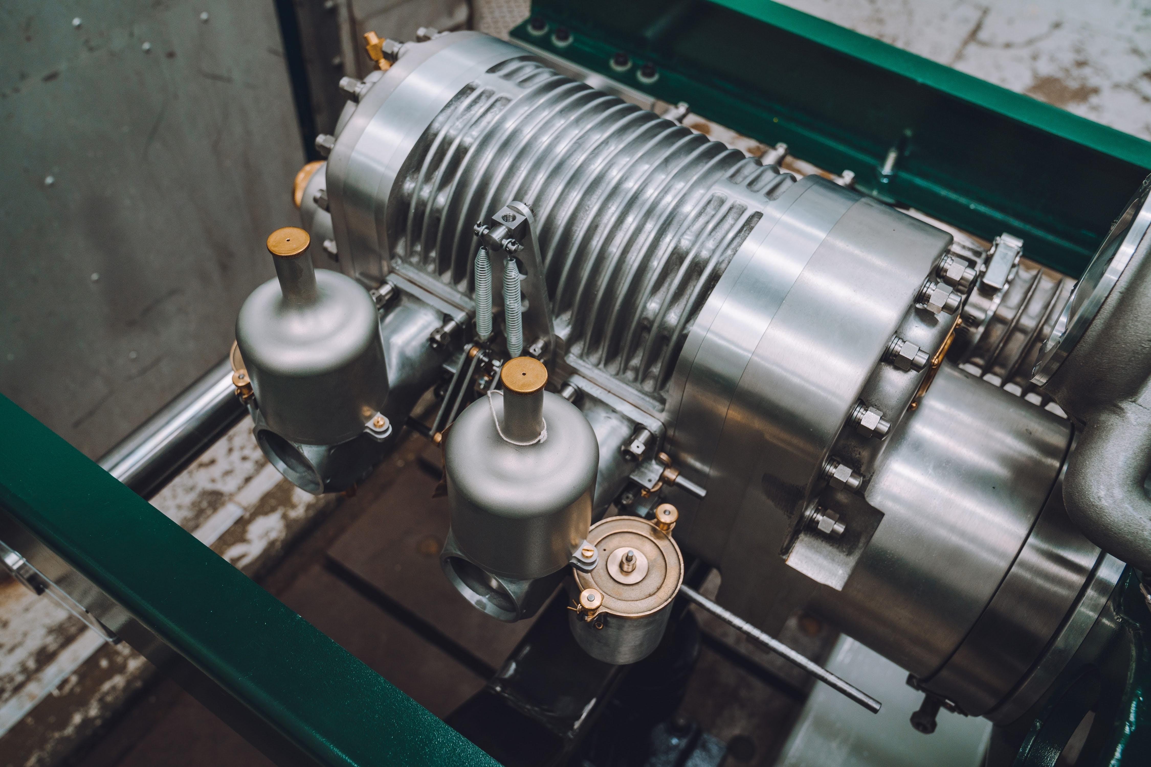
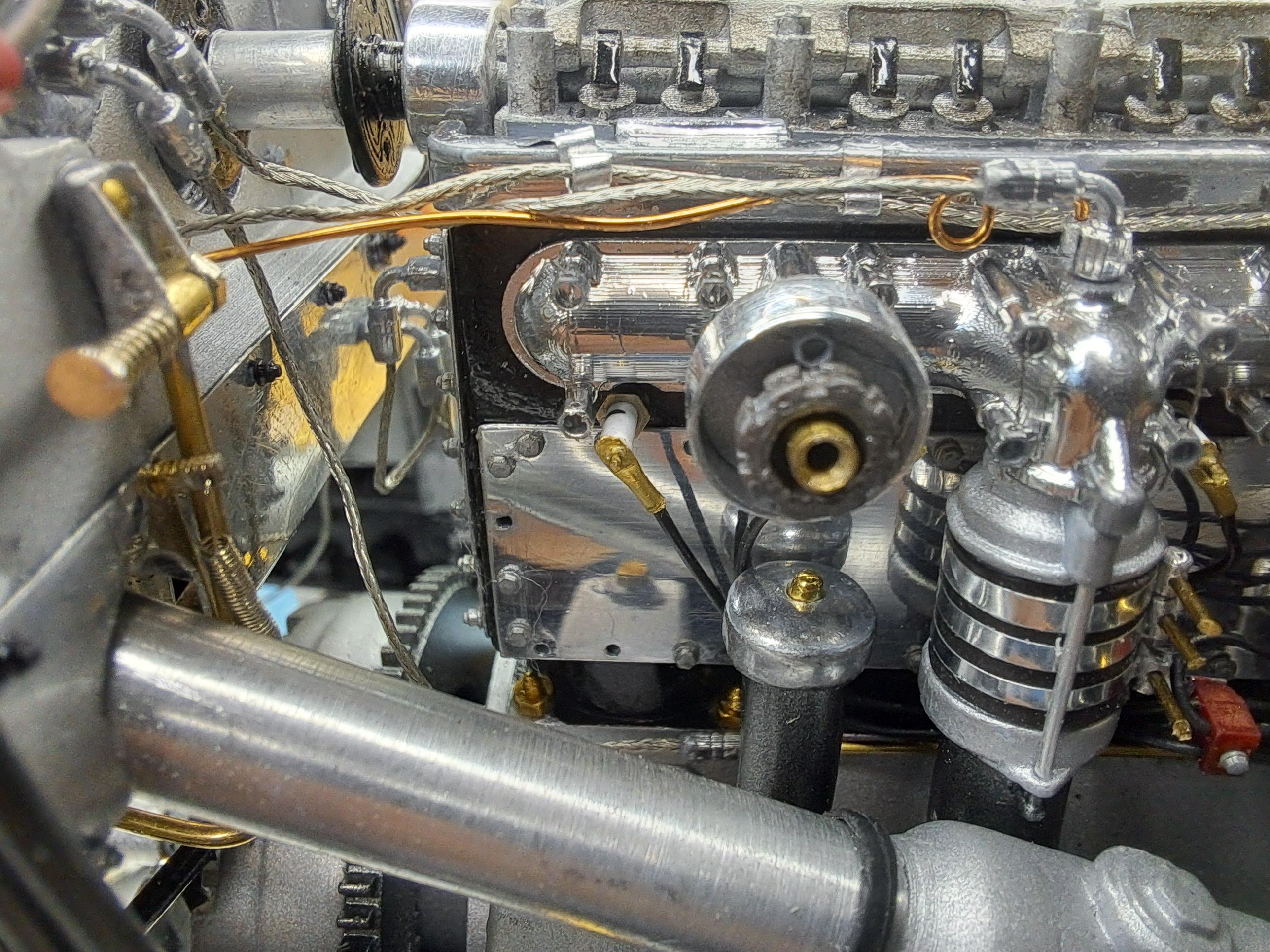
I installed the horn/ head light bracket combo today, farly satisfied with the result. Here's what I was aiming for And here's the 3d model And here's the result so far I also assembled the carburators (all 3d printed on my new resin printer) and installed them on the blower which is now connected to the engine. I just need to make the 2 brass fuel lines that go from the carbs to the fuel hoses and to add a oil feed line to the front of the blower and it will be complete. Next on the list will be to model and print proper looking lever shocks. Here are some pictures of the carbs and blower. The real thing The real thing
-
Hello everyone, I took a break from the Bentley these past few weeks in order to concentrate on my new resin printer. This thing is really hard to dial in but I'm slowly getting the hang of it, and I do mean slowly! My first try at the begining of december was promissing but since then, the results were "ok" at best. Today, I finally printed a few parts that are worthy of being used on the bentley. The horns have been glued to the kit's head light bracket And the throttle spring plate (thats the triangular plate between the carbs) has also been glue to the blower. The carbs aren't quite ready yet. It's kinda hard to see but they are 2 small lever mounted on the aluminium rod that will eventualy connect to the triangular plate via 2 extension springs. And they should (maybe) be actuated by depressing the gas pedal.
-
Still quite busy at other things but managed to try out the new resin printer I got for my birthday. I still need to make some type of enclosure with an exhaust fan, the resin has a powerful smell and I really don't want to be breathing those fumes. Here's a picture of my firts prints. From left to right, first pair not too bad, second pair printed good but I forgot to ajust the scaling and last pair is a nice print. The real part
-
I've been very busy at other things this week. Didn't even touch the new printer yet. But I did take a few hours here and there to 3d model the head lights and horns. The stock head light outter buckets are ok, they will do nicely. Same goes for the inside bucket ( they will need new chrome) and the lens. The protection grill will have to be redone. The mounting brackets and horn will also be new. This is the kit's horn. My modeled front end the ref car's front end The head light mounting bracket A tool I printed to form the bracket A full view of my 3d model to date Same view of ref car
-
I got a new 12k resin printer for my birthday, I can't wait to try it out.
-
Only did a bit of cad work today. I decided it was time to tackle the blower unit and carburators. The blower itself is ok, adding some nuts and bolts plus a few fittings for oil connections will bring it to par. The problem is with the carburators. I'll have to print the throttle bodies and the float chambers. The damper pots should be ok. I'll add a throttle shaft with a few levers and springs and spring mounting plate. Again, if all goes to plan, the throttle shaft should rotate by depressing the gas pedal. Here the real deal The kit's carburators And my 3d model
-
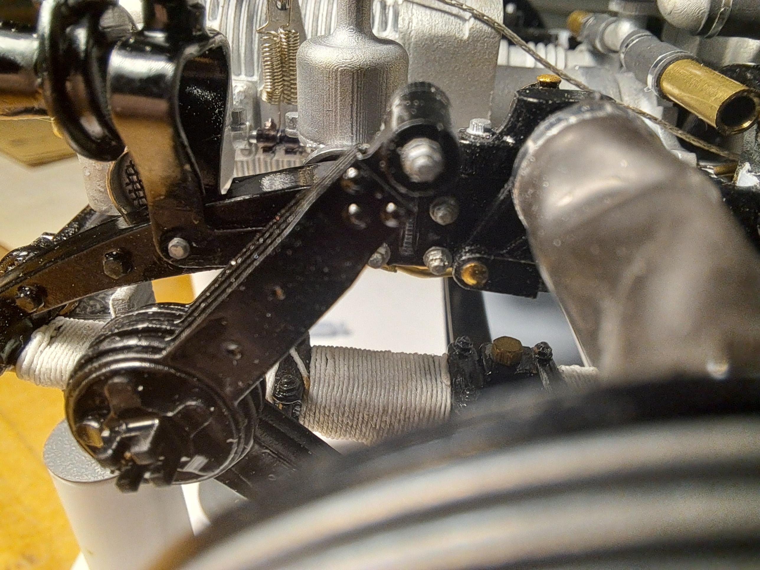
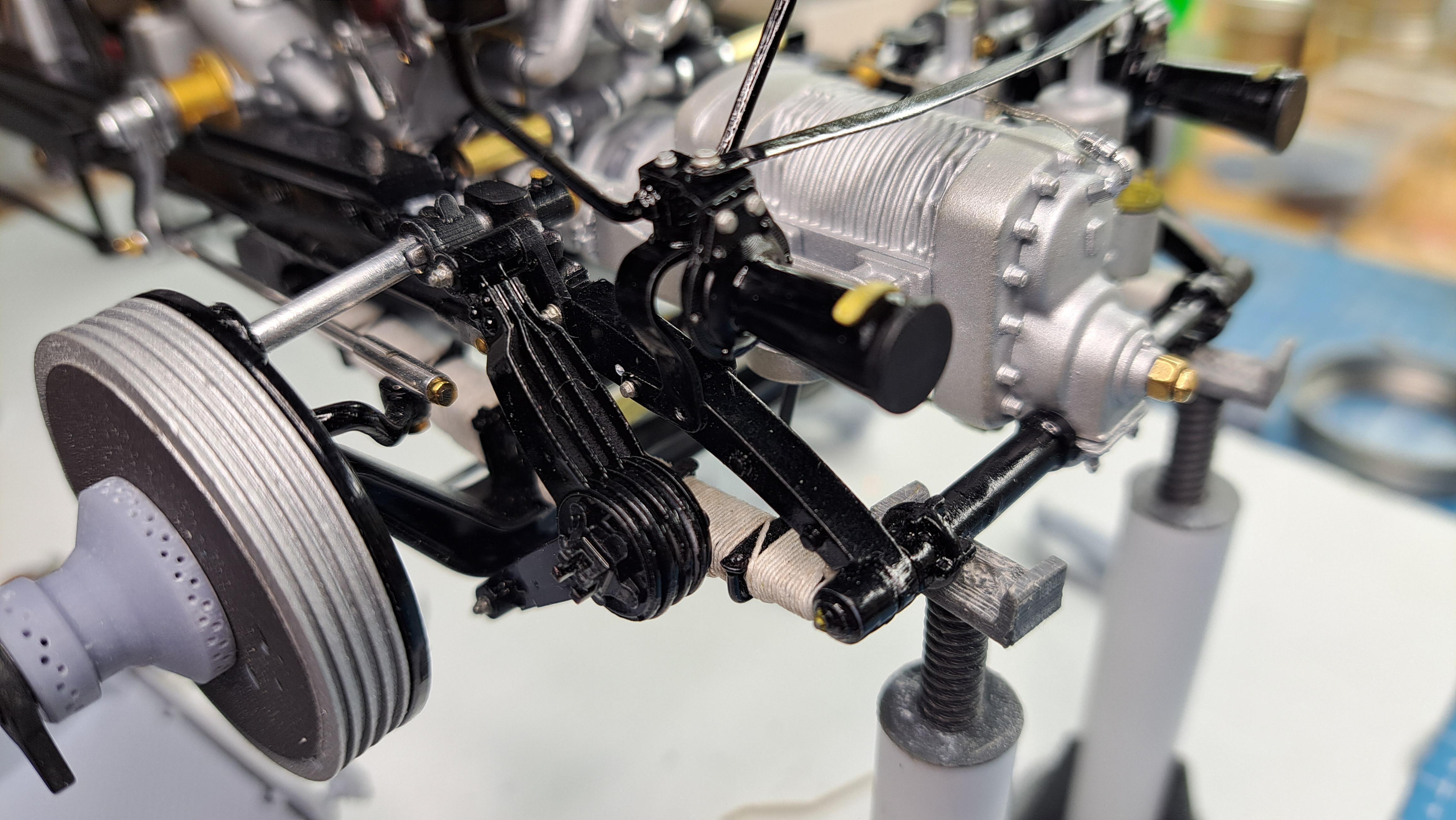
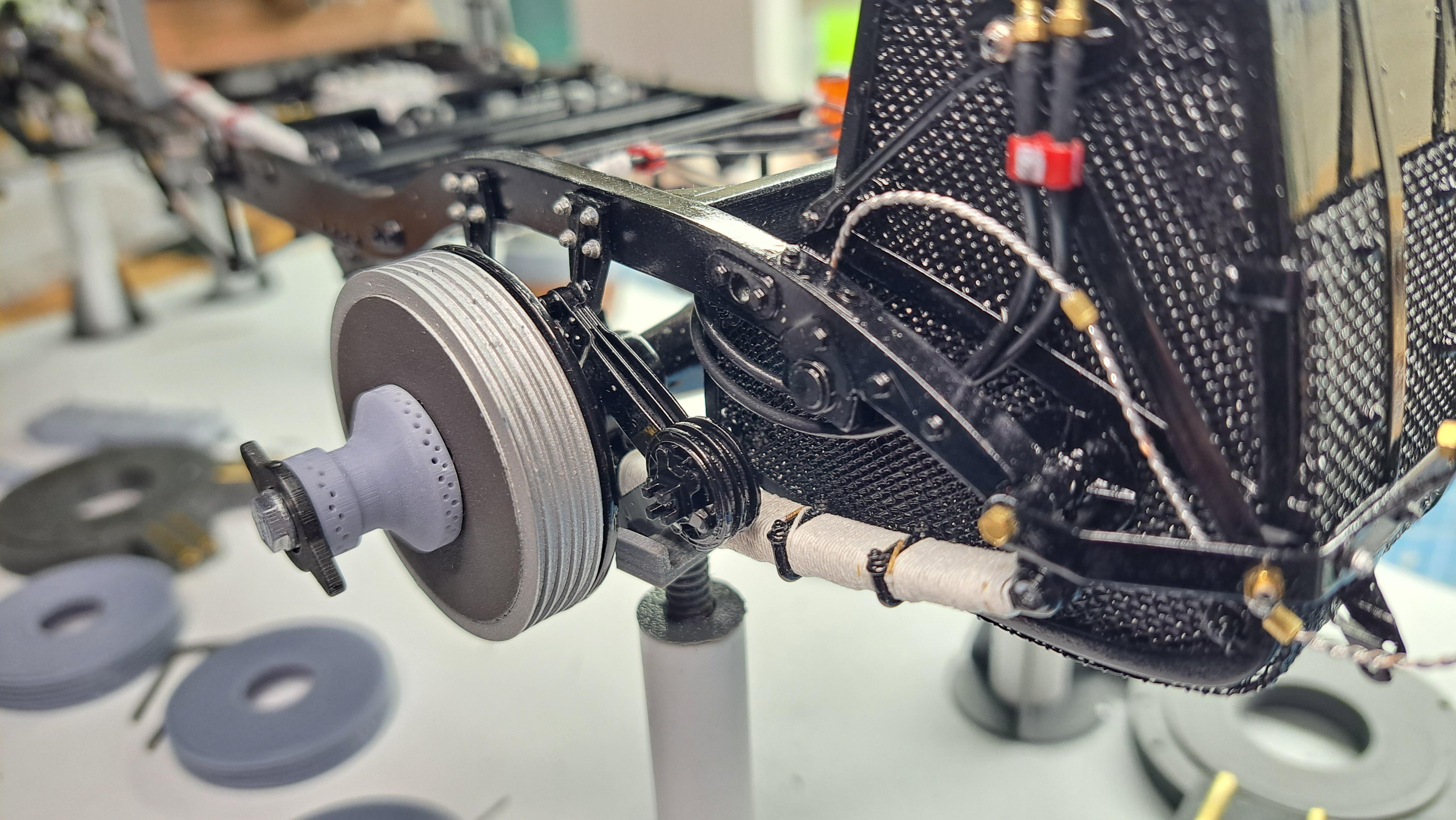
I few more details were done today. Hooked up the steering 20231123_120637.mp4 Attached the gas pedal to throttle linkage 20231123_112600.mp4 Added the blower manifold copper oil line Added the starter ground cable
-
I thought it would be fun to show some comparison pictures. 1930 2023 1930 2023
-
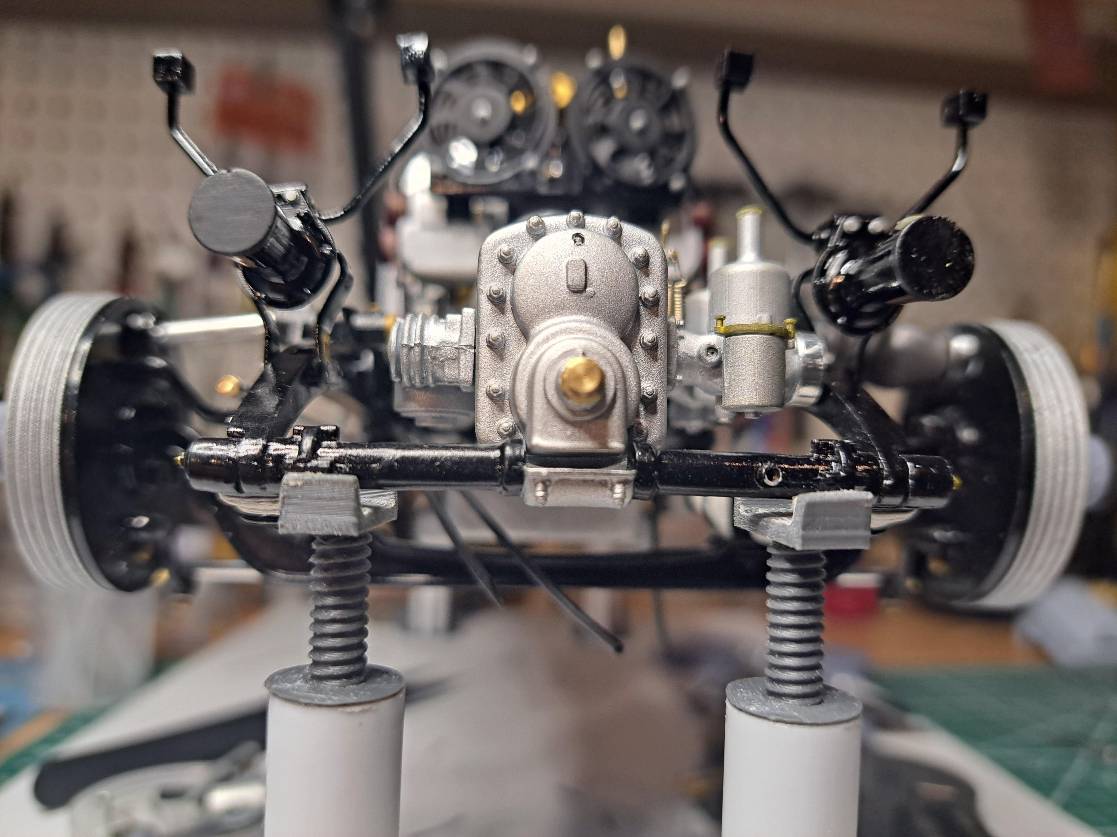
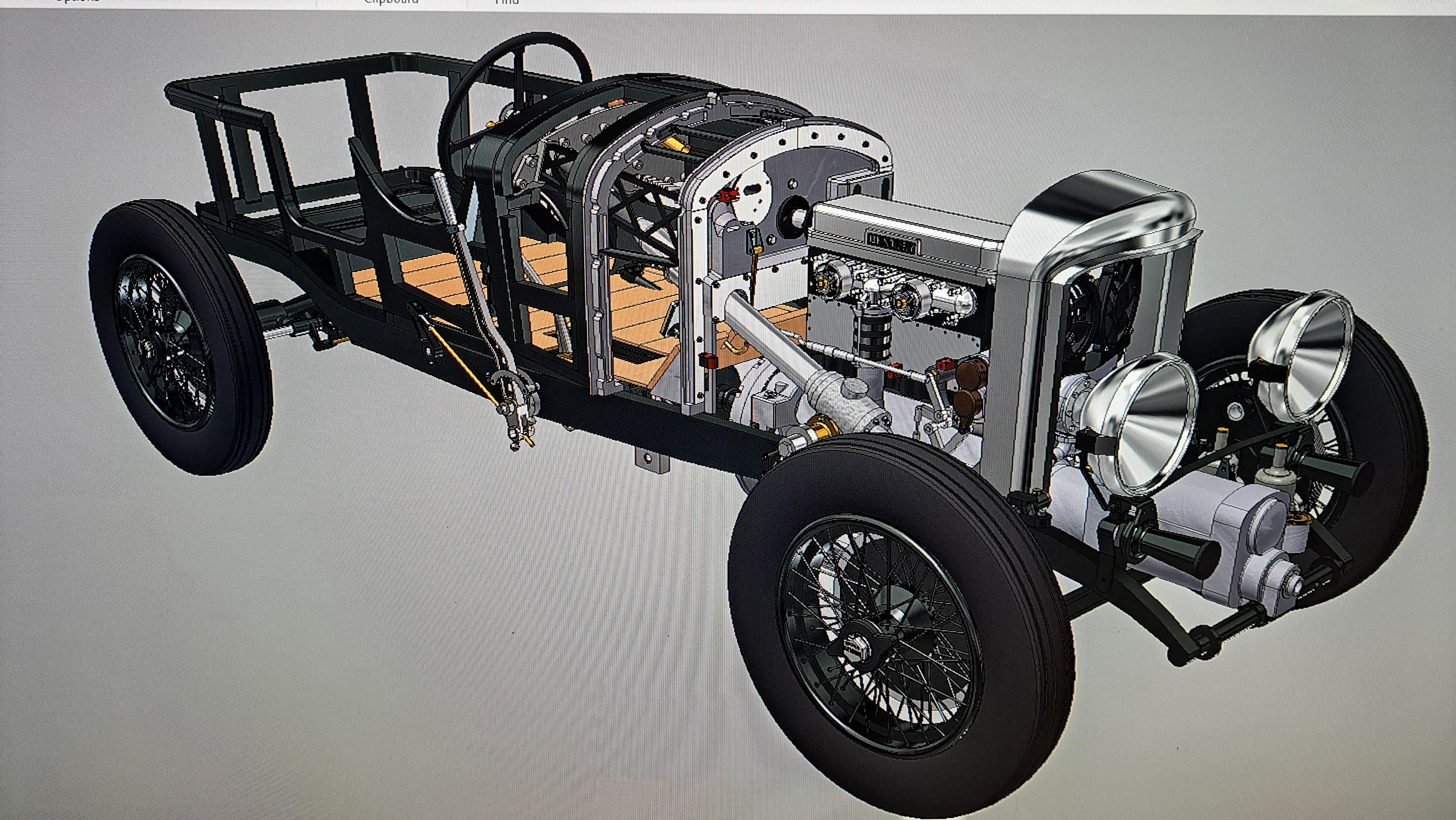
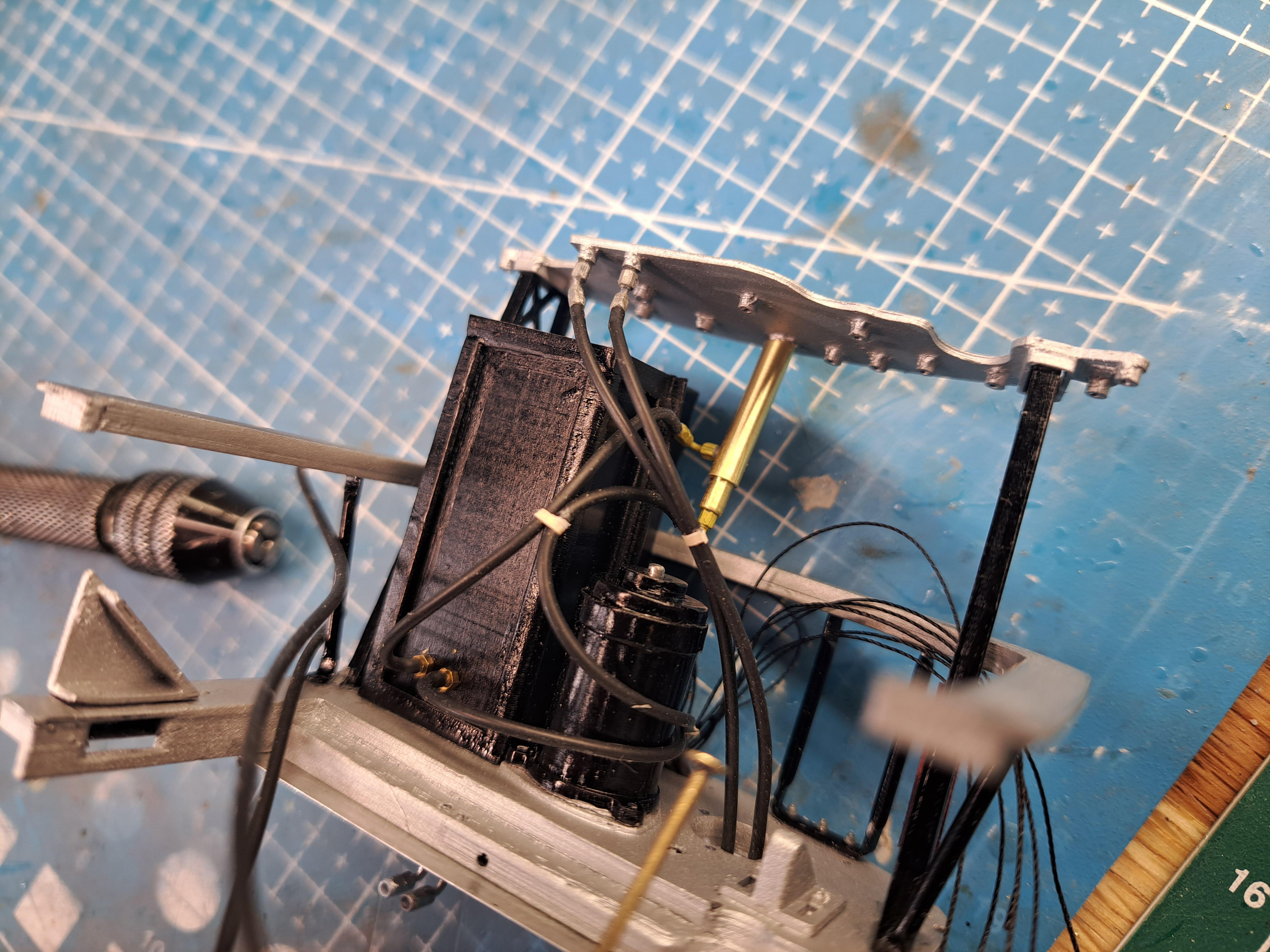
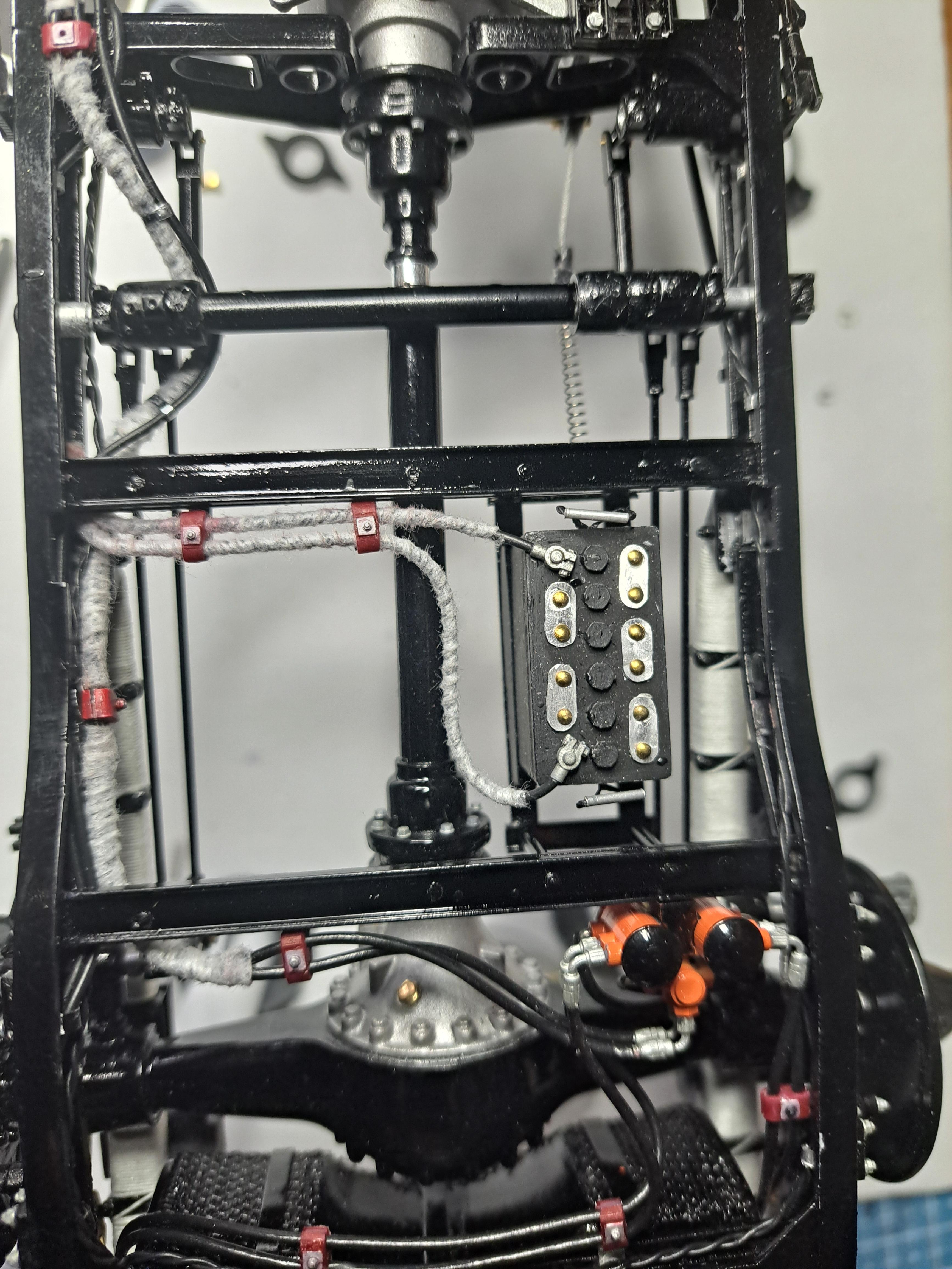
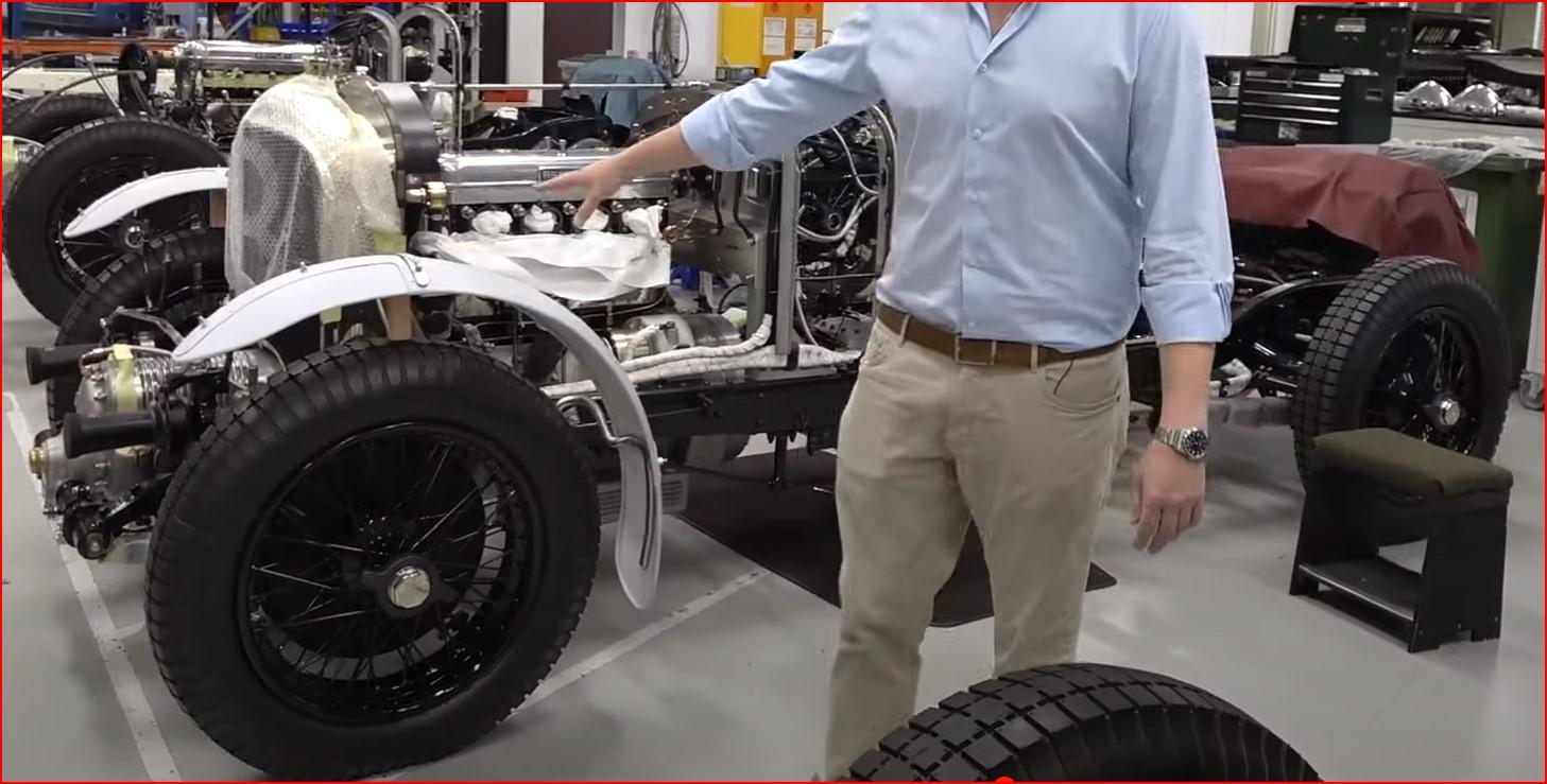
Alot was done today. -All wiring and plumping of the bulkhead assy is complete 20231122_090355.mp4 -the engine and bulkhead assy are installed, and when connected to a battery, the engine turns along with the drive shaft differentiel and rear wheels 20231122_174244.mp4 20231122_174412.mp4 -speedo drive housing installed on transmission and wired to dash, -inclined floor board (the one just in front of the pedal) installed. here's a link to my build album https://photos.app.goo.gl/p2DahEAtoFRgju8eA


.jpg.c209d787d6776eb4d9b66c385b204b85.jpg)