François
-
Posts
489 -
Joined
-
Last visited
Content Type
Profiles
Forums
Events
Gallery
Everything posted by François
-
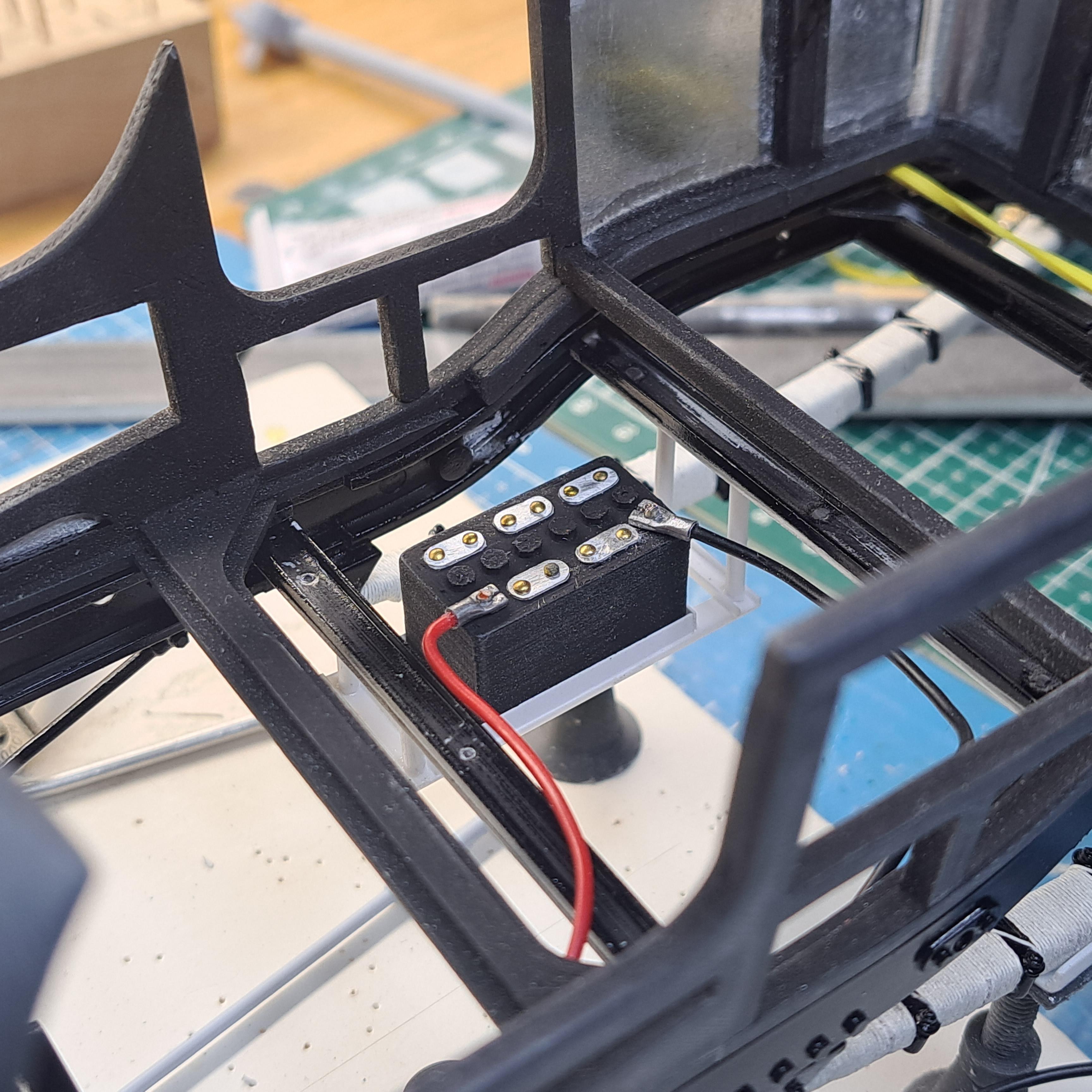
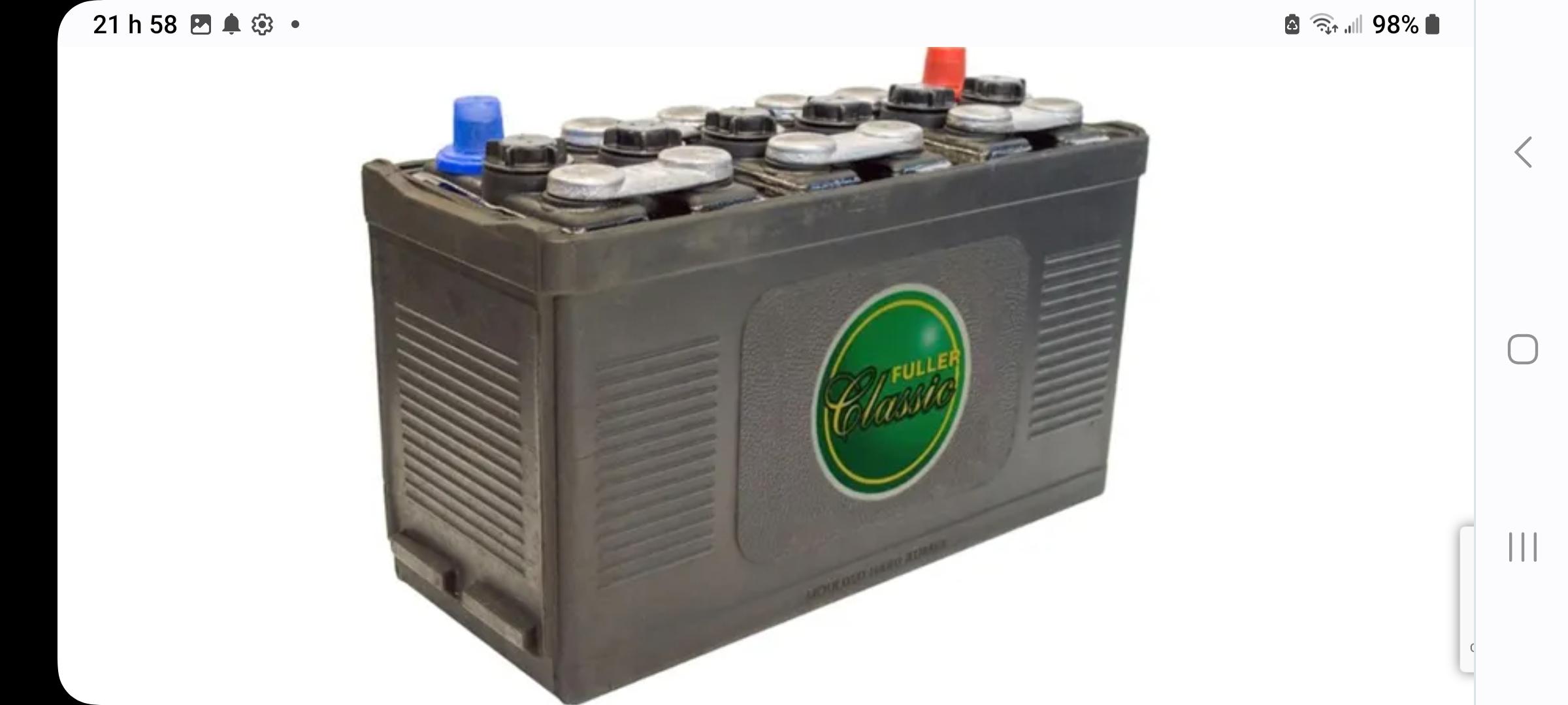
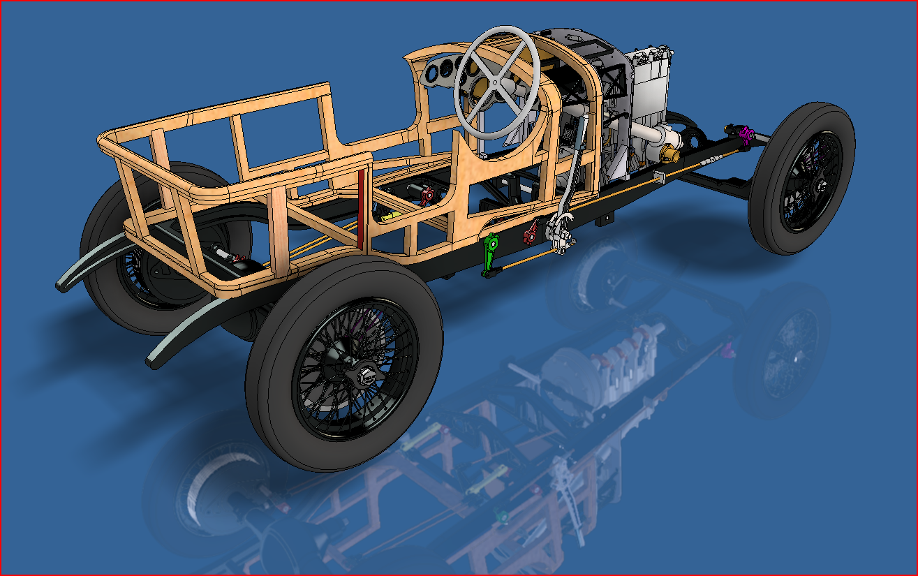
Ok, so after about 5 minutes of mulling, I redid the battery and the rack. Here's what it looks like on the continuation car (and Birkin's also) The 3d remoldeled And the new battery and rack I based the battery on a vintage part offered on a Bentley spare parts site

-
Thanks peteski ,I've searched a bit more and have found out that the Tim Birkin car, on which my ref car is based, had only one 12 volt battery mounted under the floor on the drivers side. I'll mull it over tonight but I'll probably redo the battery tray and make one 12 volt battery. What bugs me the most is that I had just painted the frame yesterday. Oh well, live and learn!!
-
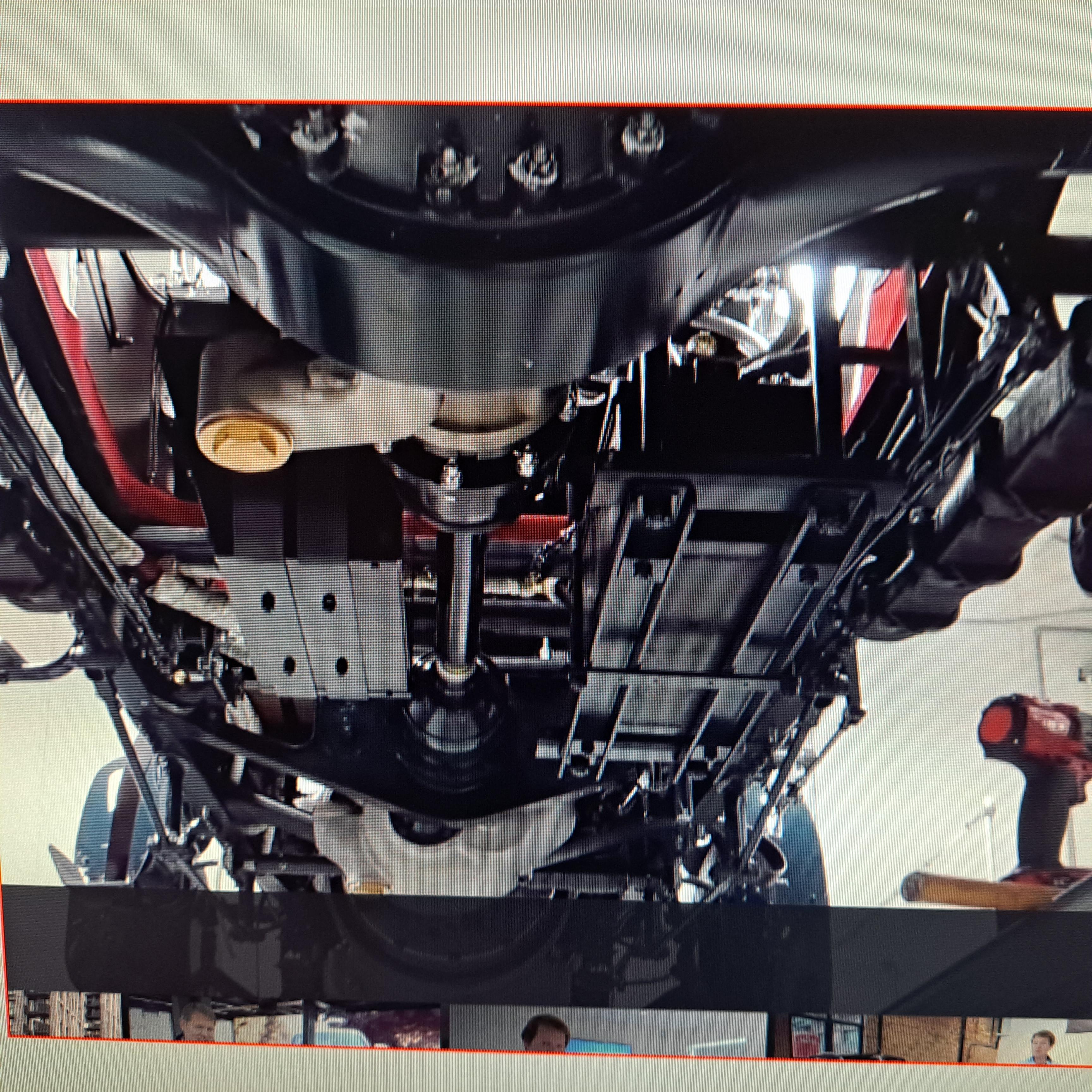
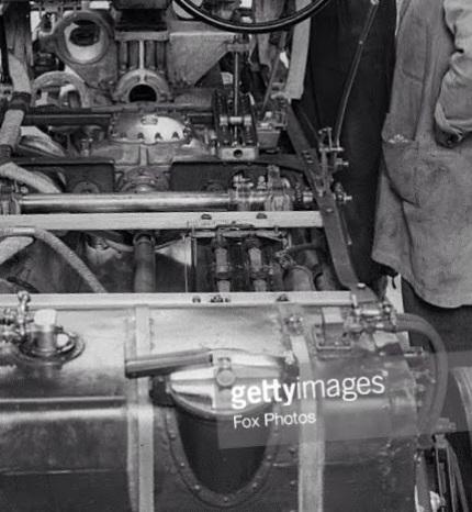
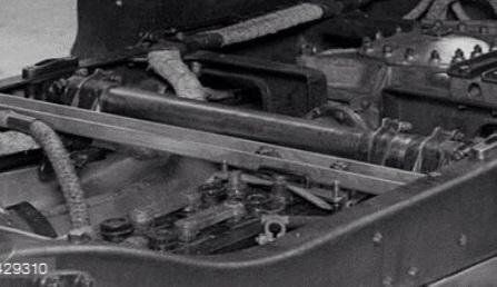
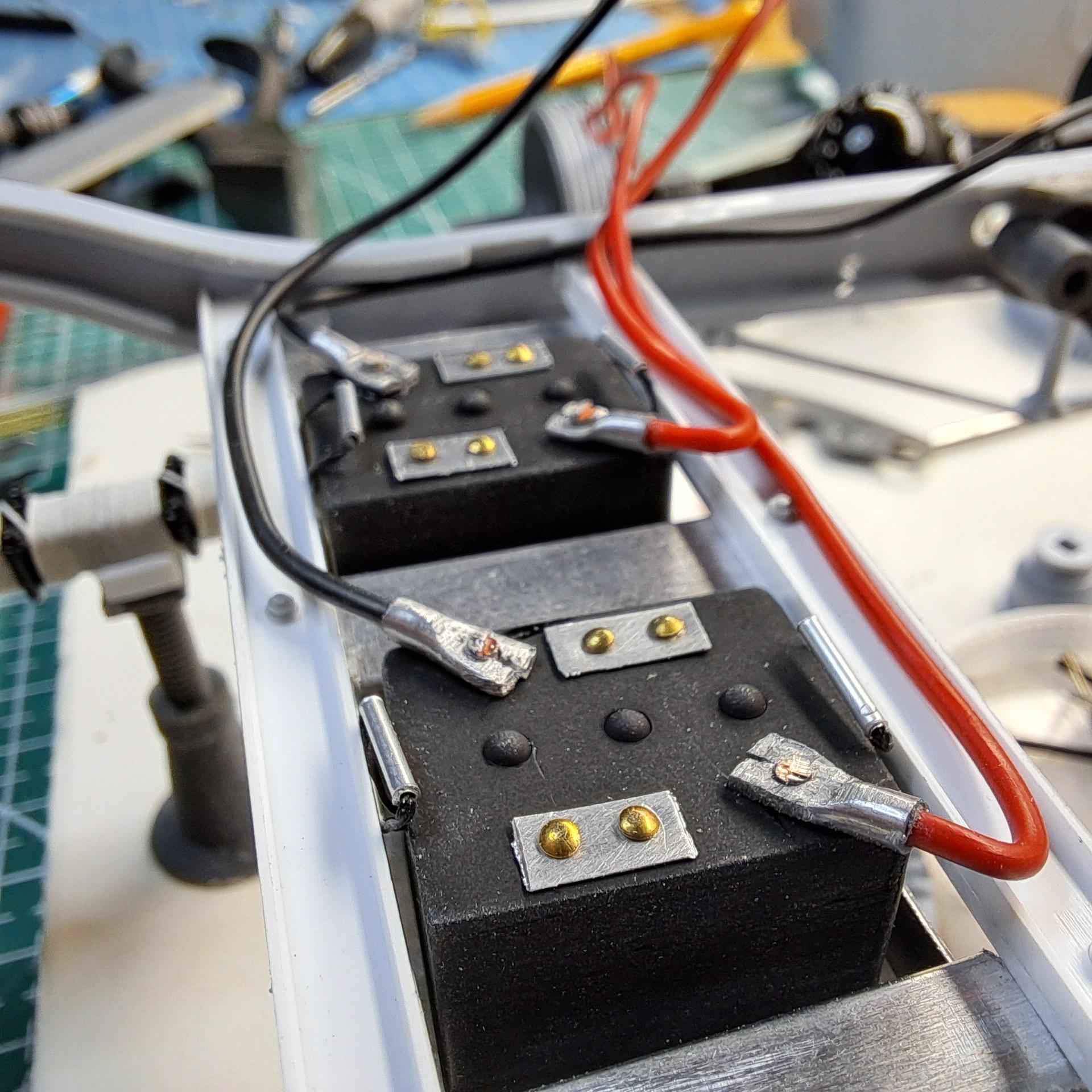
Not much info on the web about the wire color but in the boating world, where serie connected batteries seem to be commun, the consensus is red with a black tape applied at the neg end. So I guess I'll leave it red. As for the location, I took a closer look at my picture gallery and found this. It's very fussy but it clearly shows a battery located in the frame. It would have been under the floor boards.
-
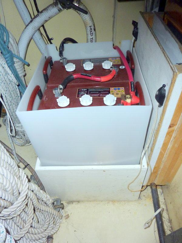
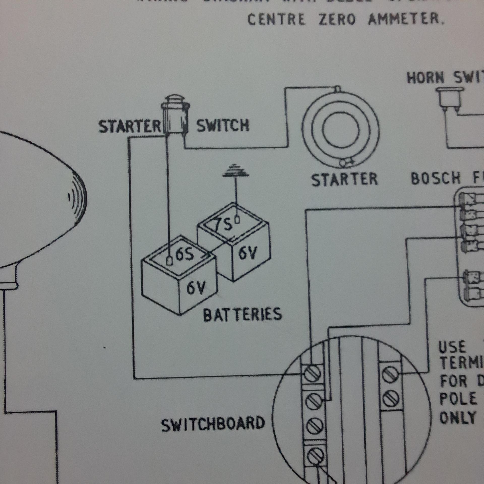
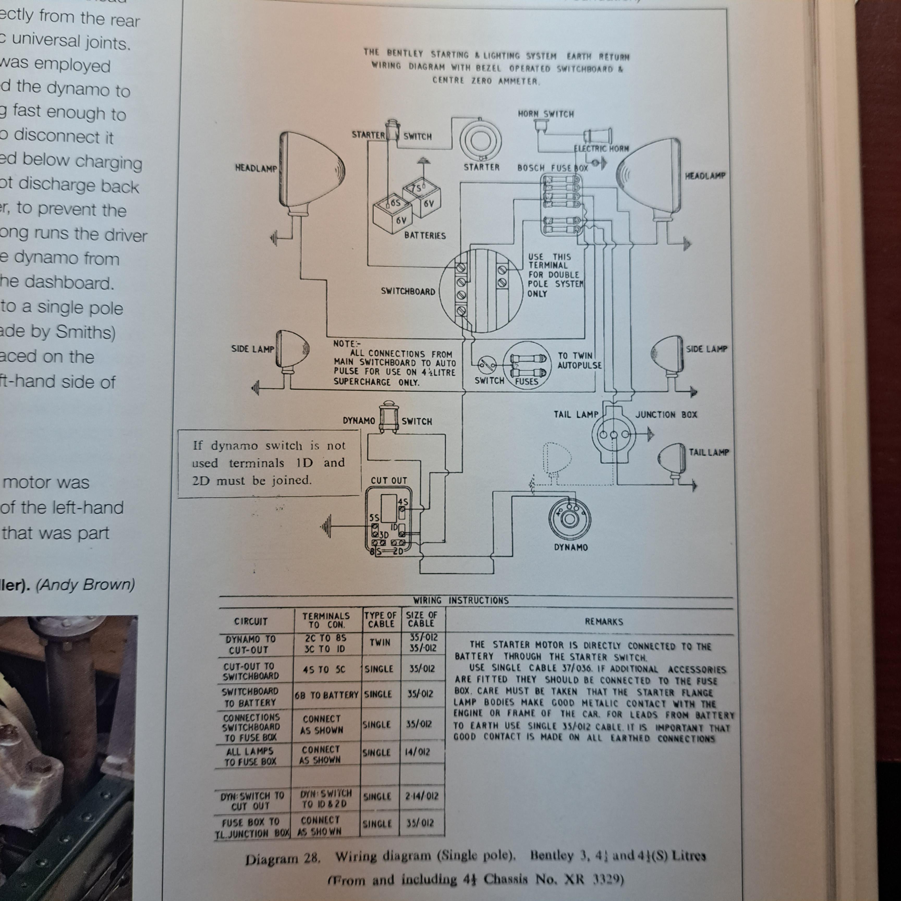
Thanks peteski I found this. It would seem that the two 6 volts battery in series is correct. Should the wire going from the positive to negative be black or is red ok? I still don't know where they were located but under the floor seems like as good a place as any. They certainly were not in the engine bay, that would have been very easy to find in pictures.
-
That's part of my problem peteski, I can't find any pictures of the battery setup on the 1:1. When you say connected in series, you mean one connecter to the other and from there going to the starter and whatnots ?
-
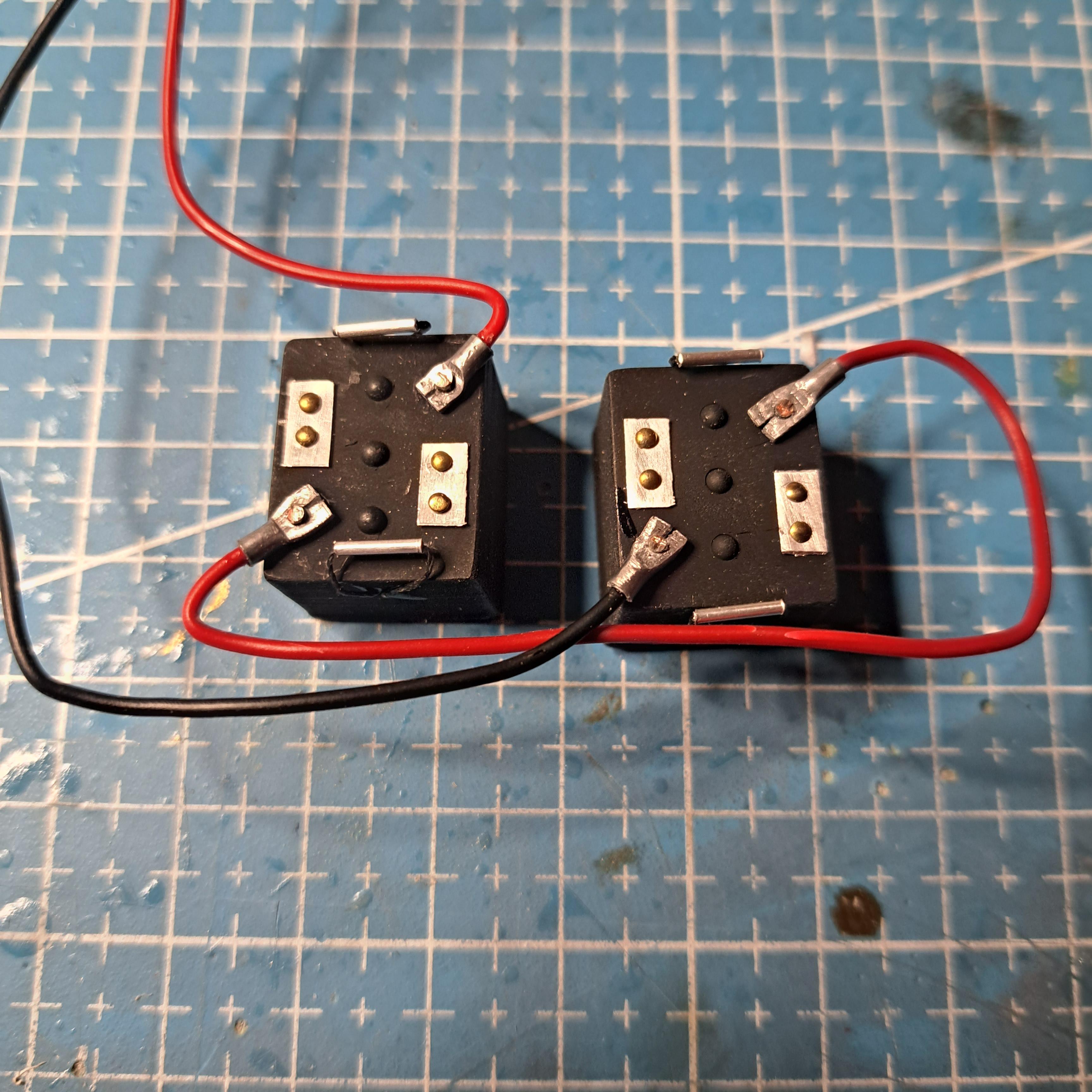
Big John, I know a lot about the mecanical aspect of cars but praticaly nothing about the electrical. I'll take your word for it that they are 6 volts. I finished the batteries today, quite happy with the result. my inspiration for these batteries came from John Teresi's bentley built back in 2012. I did change a few things from is design.
-
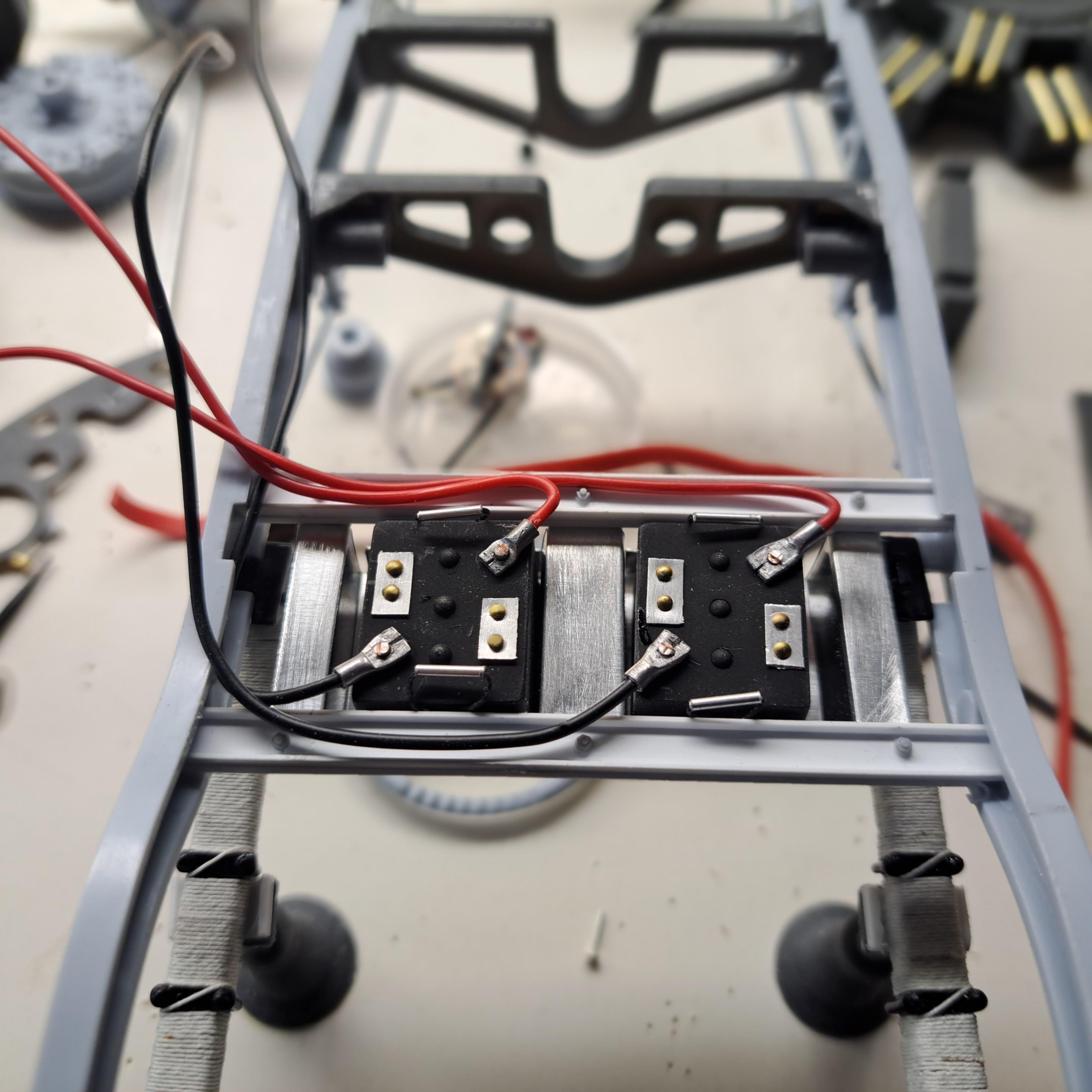
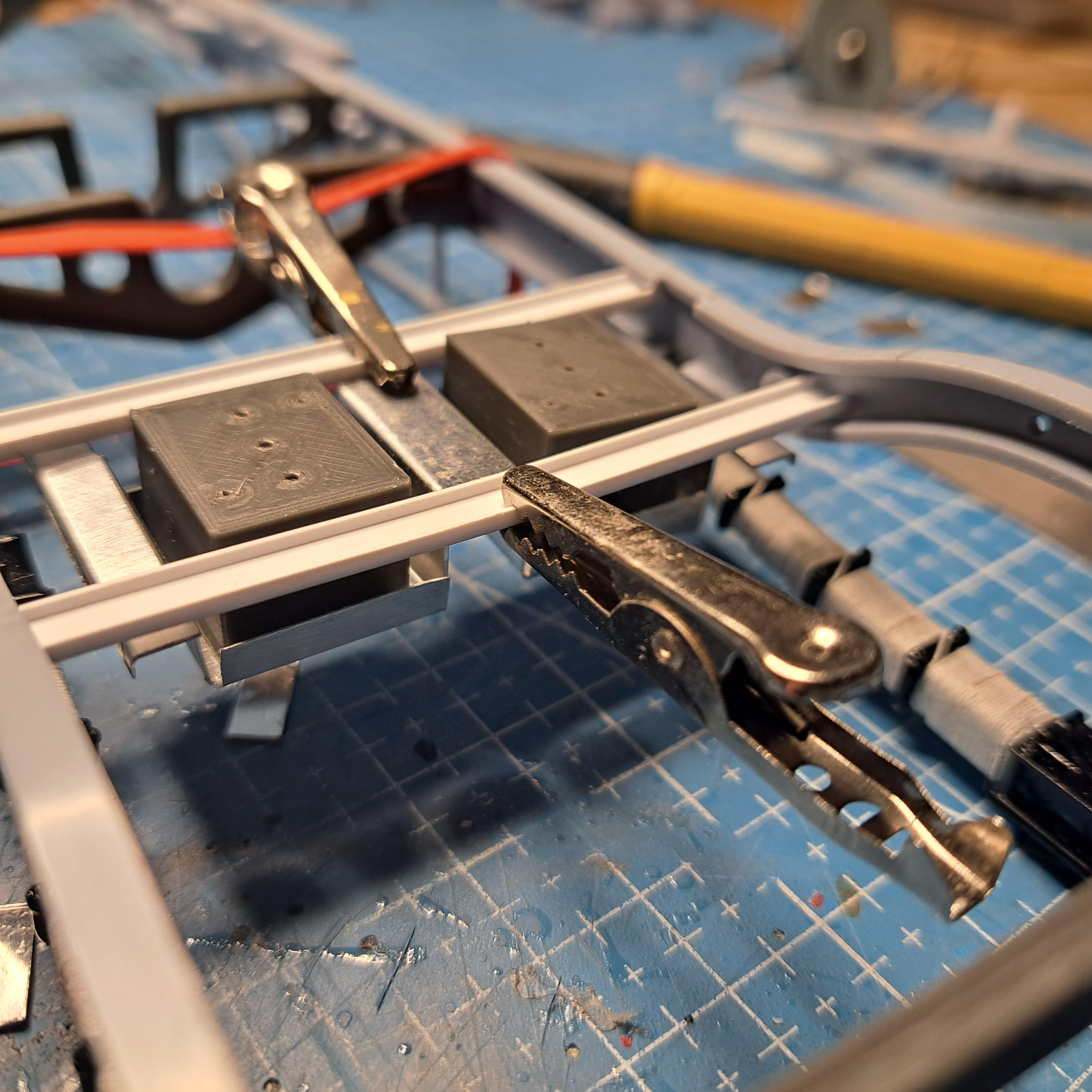
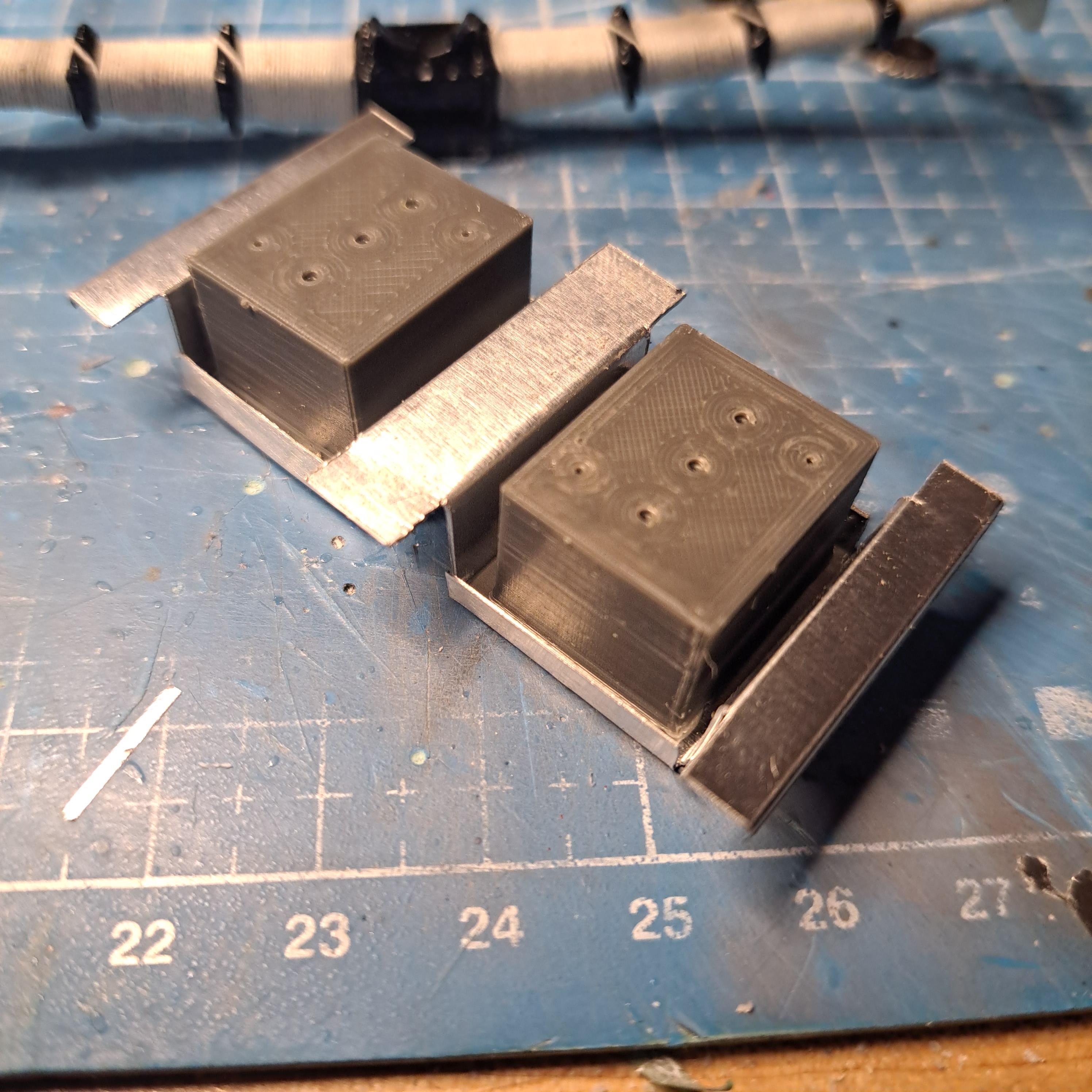
As I was preparing the frame for paint, I realised that I forgot to install the battery box support. I could not find any info for this on the continuation series recently built and not much more on the original ones. So I winged it a bit. I also based my design on a previous built done back in 2012. I added 2 'c' channels that will hold an aluminium battery box. the 2 cubes will eventualy be the batteries onces dressed up.
-
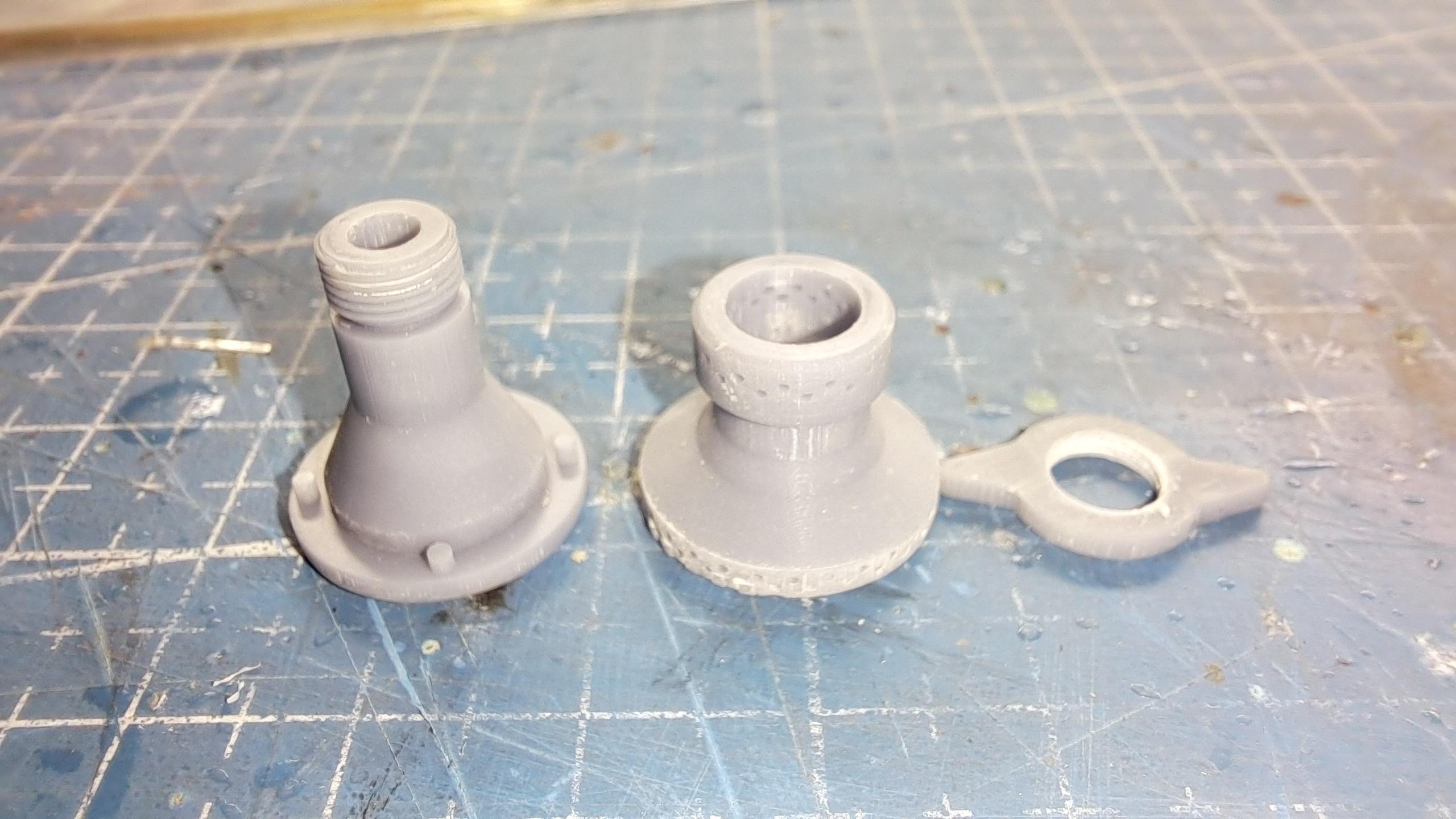
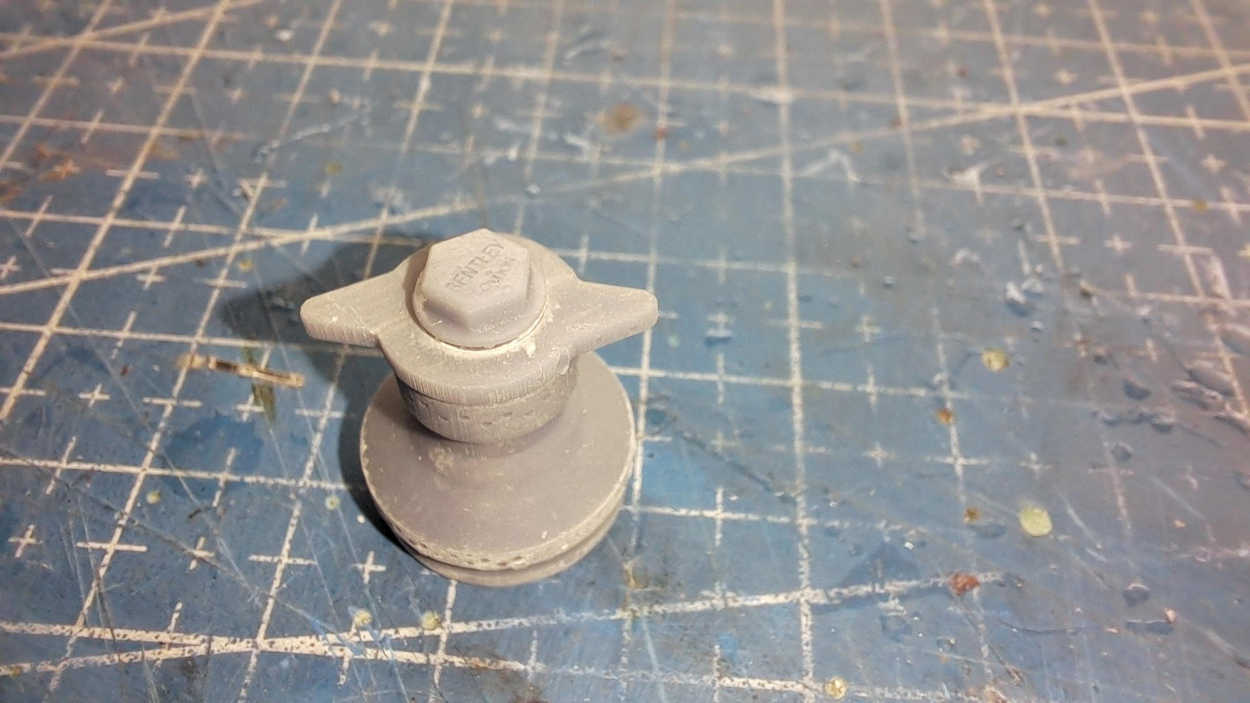
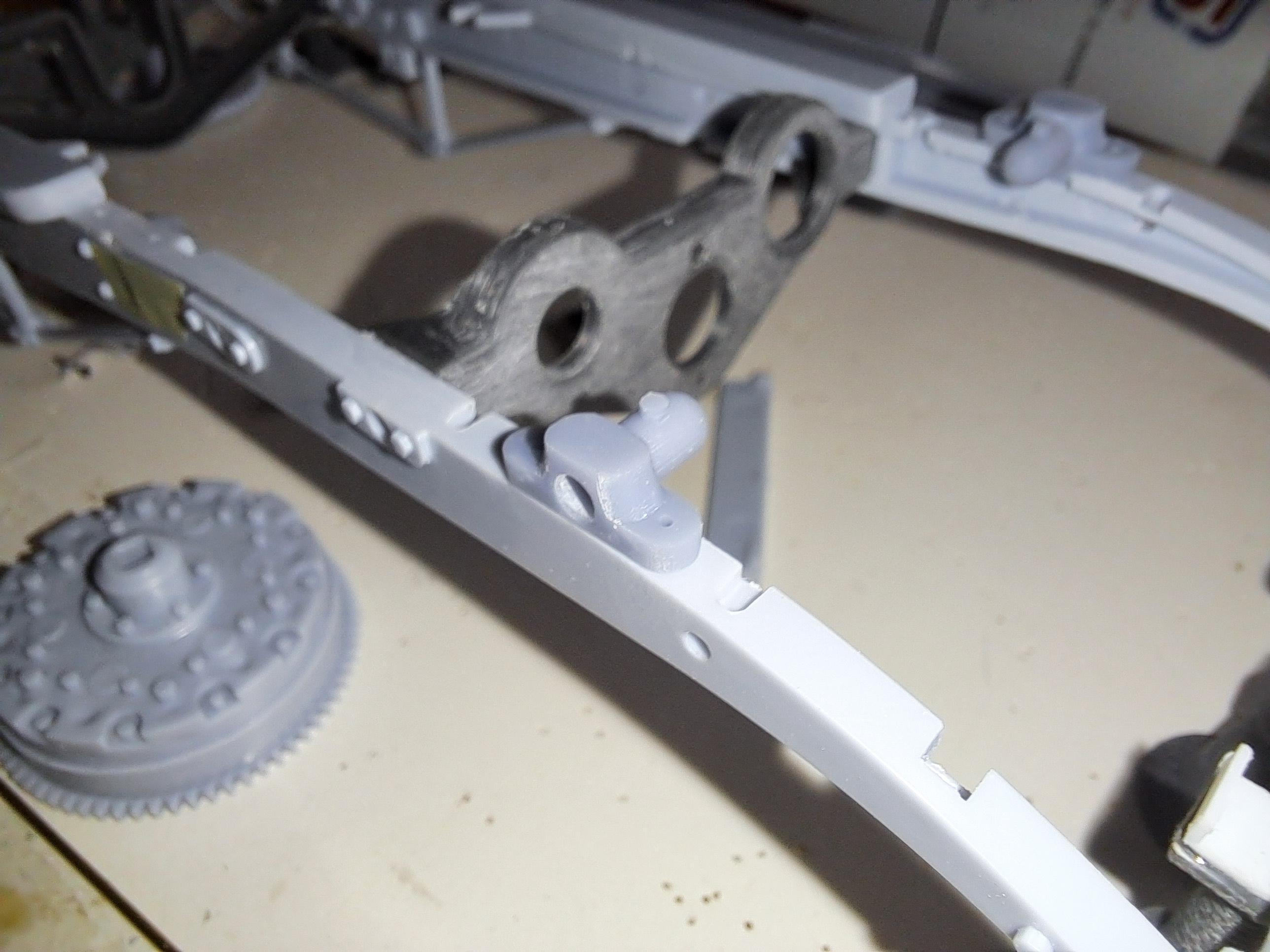
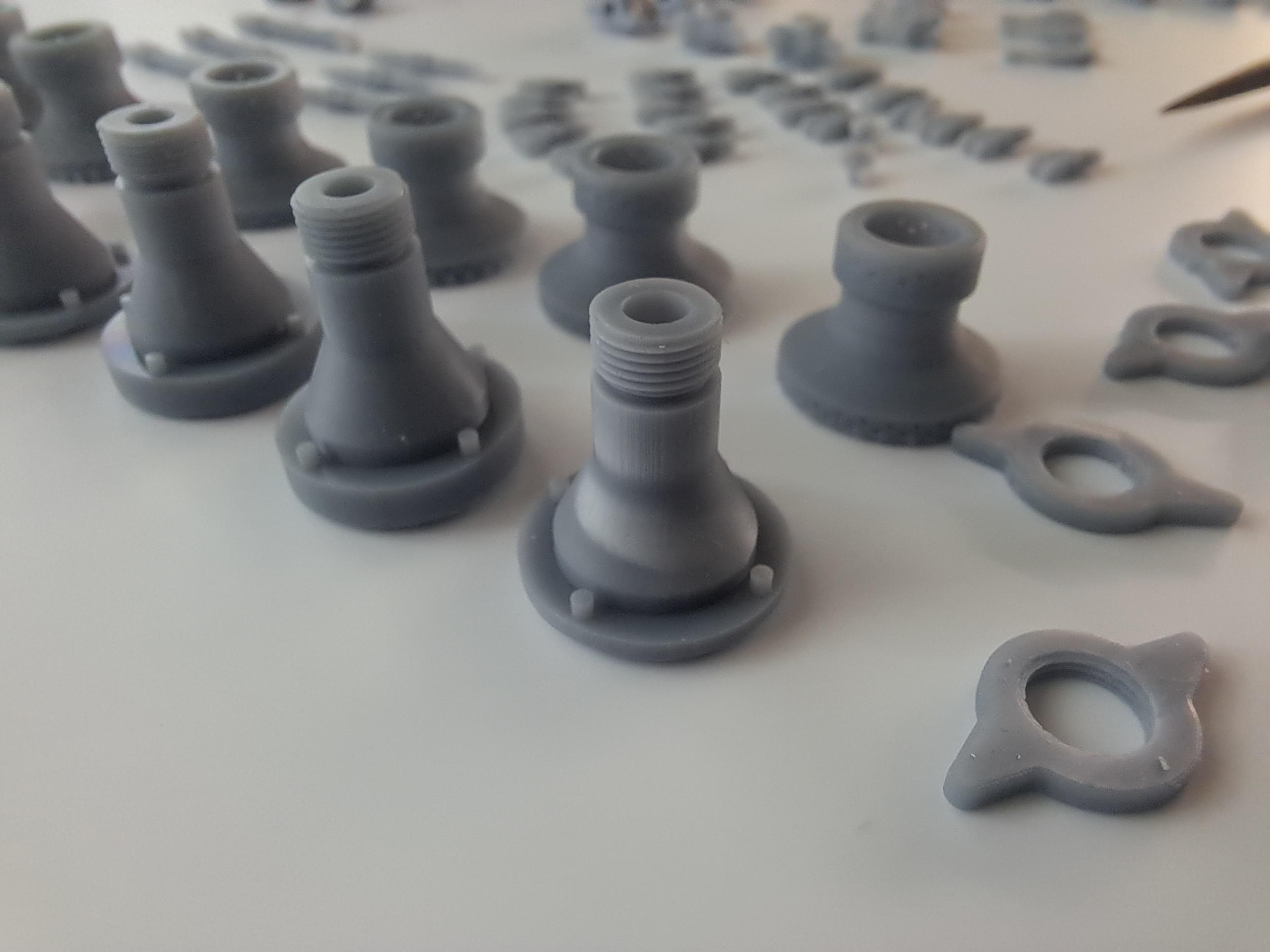
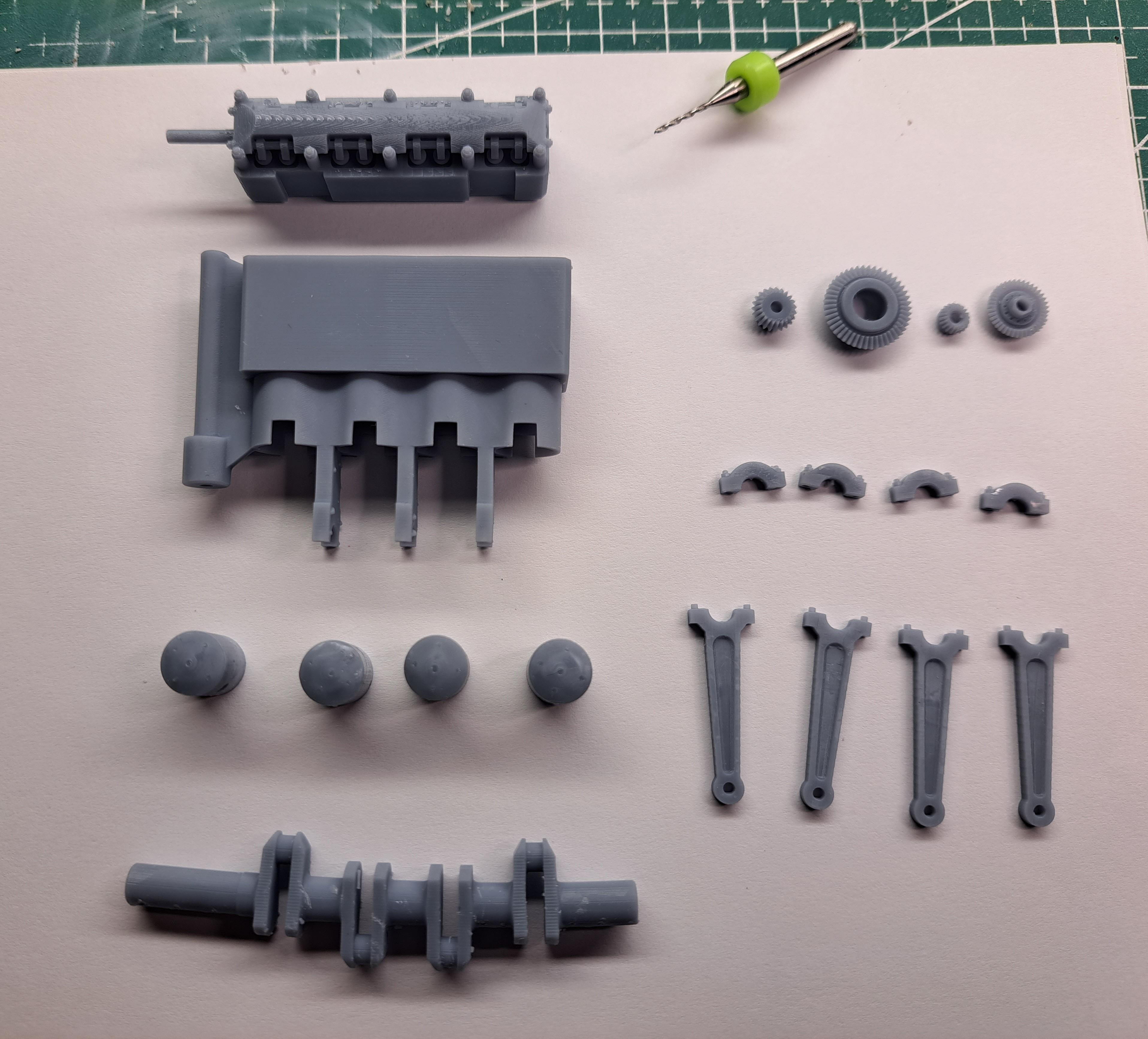
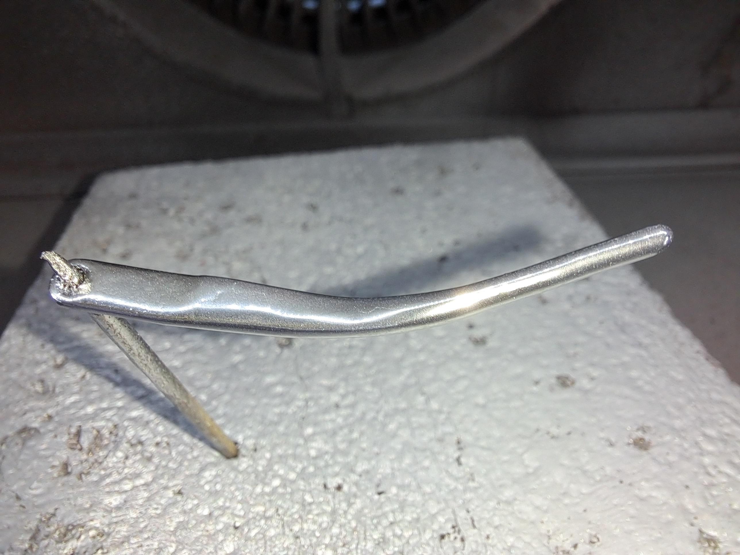
I'm back on the Bentley. Did a bit of prep work on the resin print batch i received. I should do a bit of painting later this week. Here are a few pictures. Brake compensator shaft assy Front brake lever shaft hub Wheel hub assy with knockoff(It really screws on!!)
-
Well, another completed project. The painting will be done by the customer. It was a different build for me but still very fun. So now, it's back to the Bentley !!
-
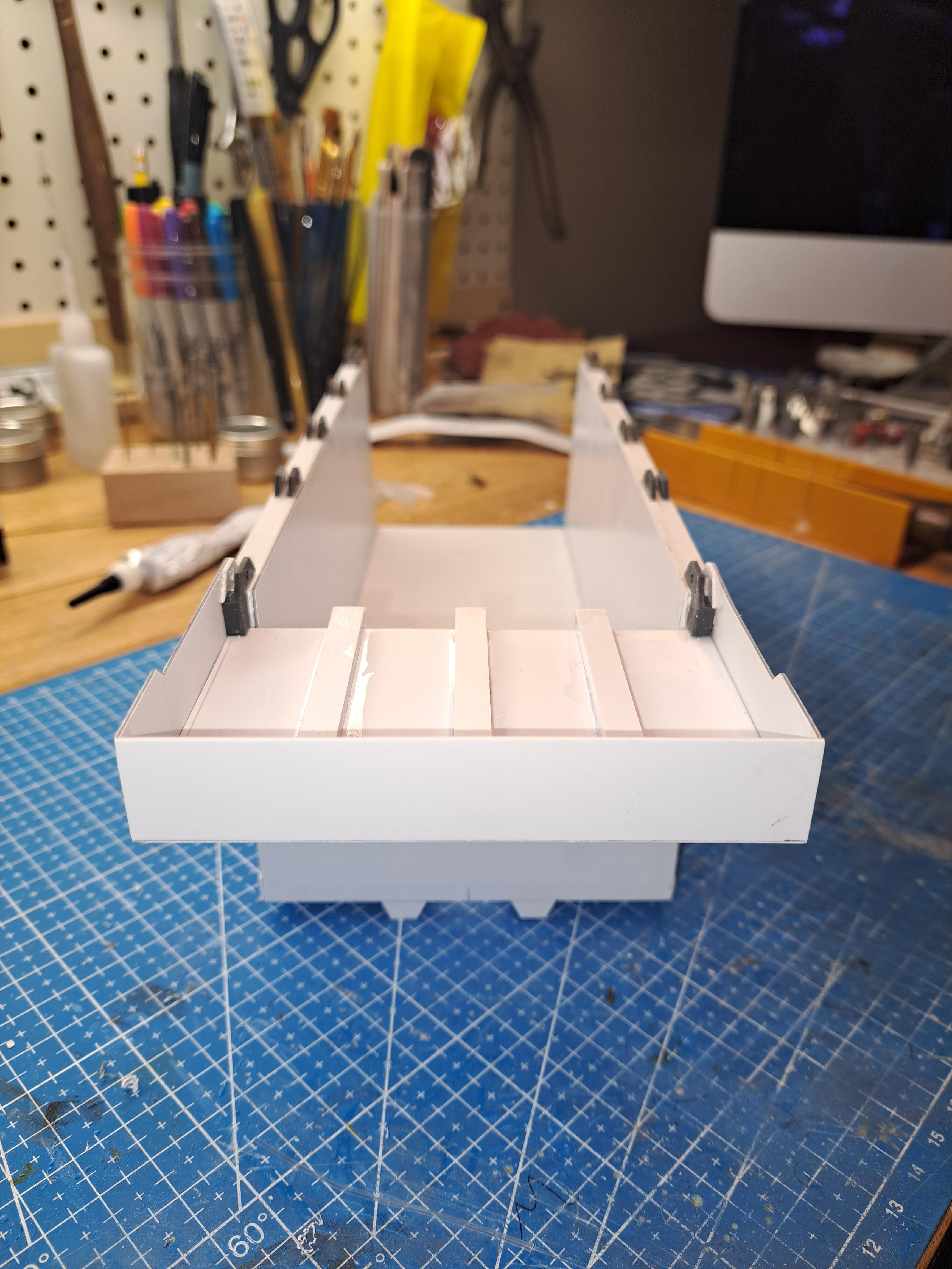
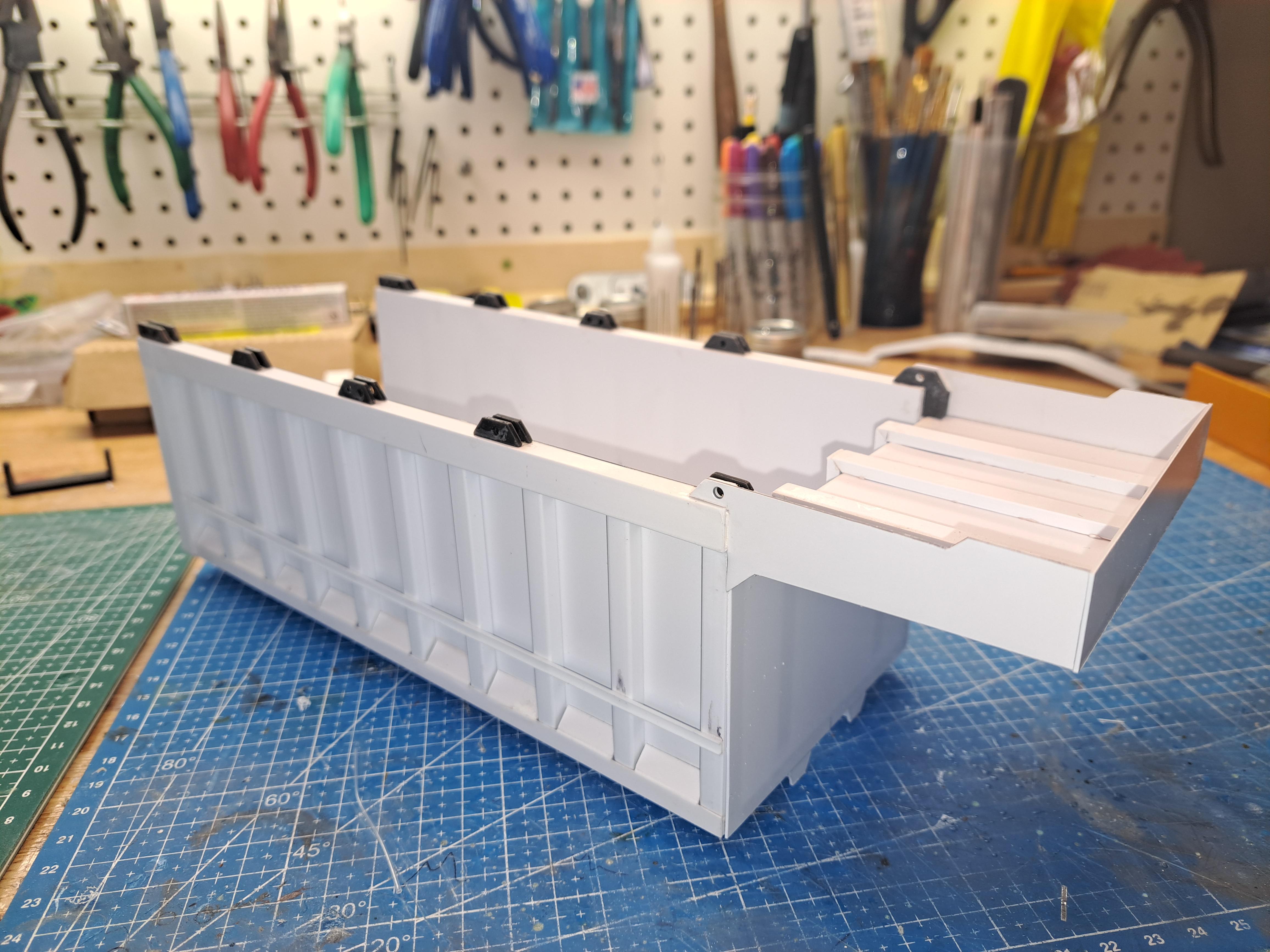
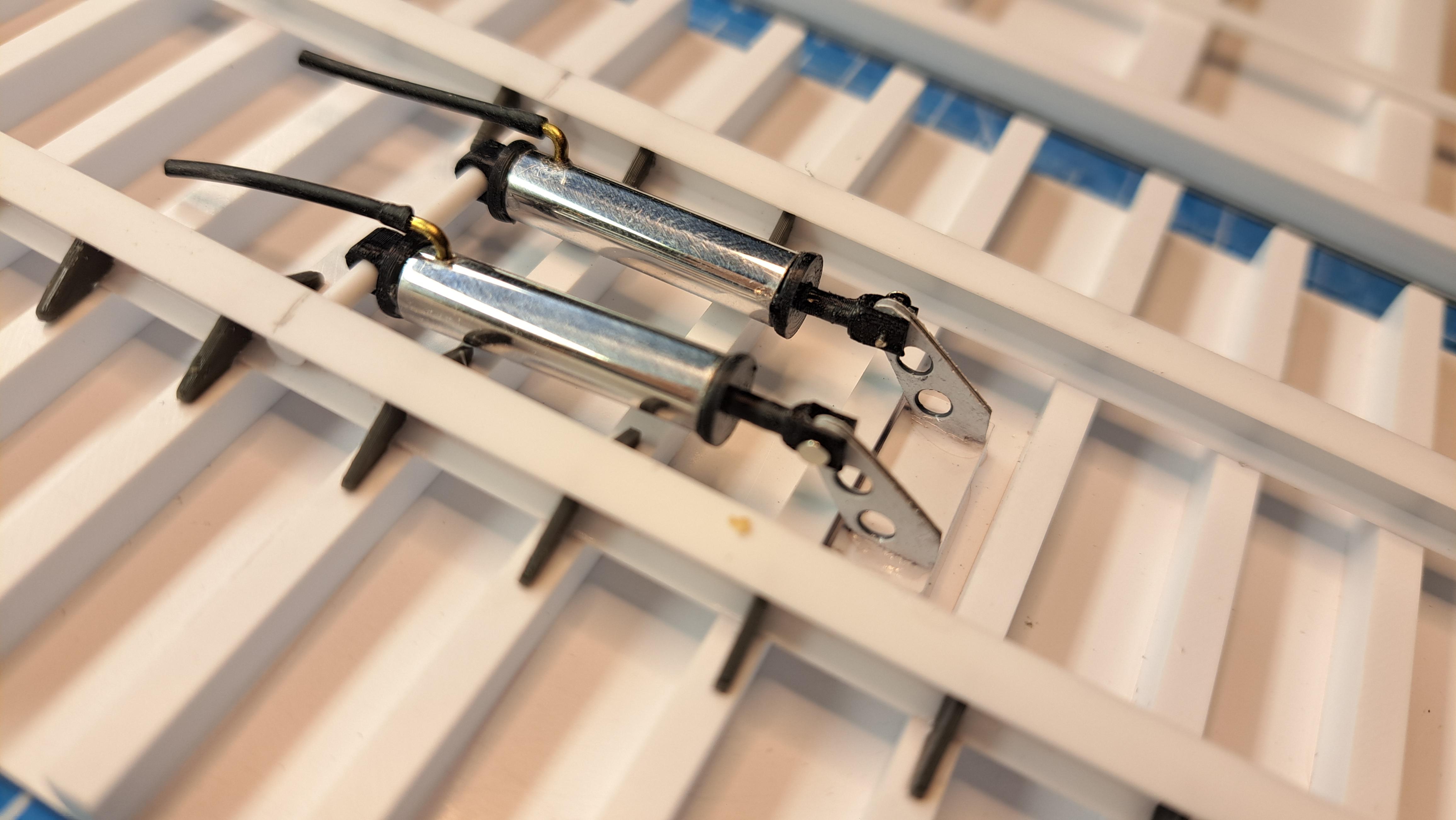
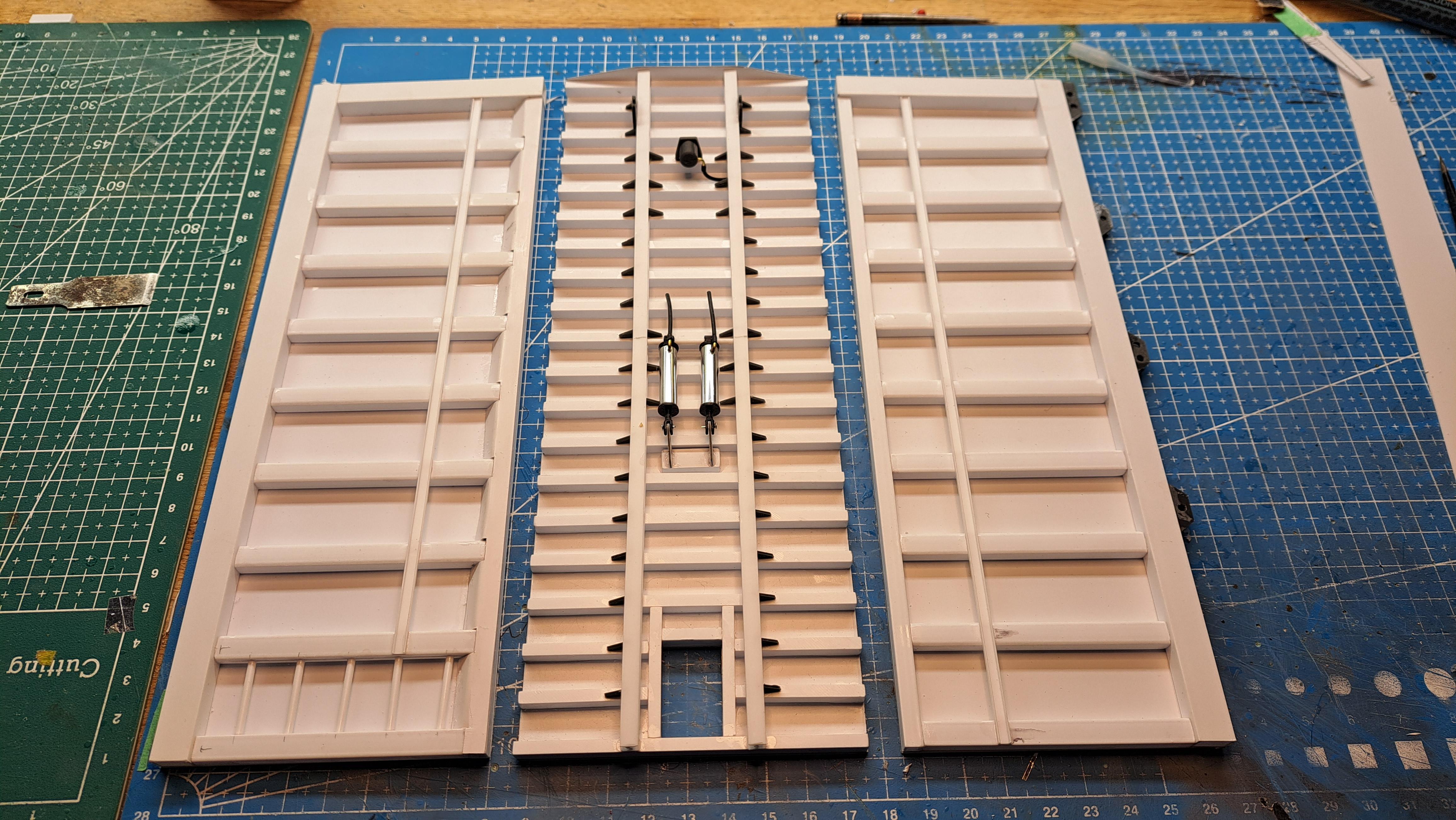
Did the telescopic cylinder today, and it actually works using my airbrush compressor. Also simulated the welds on the dump body using tamiya putty and a custom printed super thin nozzle. The brass tubing will be replaced by an aluminium part.
-
Hello all, it's been a while since my last post. I've been busy with another project but should be getting back on the Bentley soon. I received a bunch of resin printed parts today. So I'll be able to start on the wire wheels and the brake linkage. Still waiting for the. 3mm neoprene for the body.
-
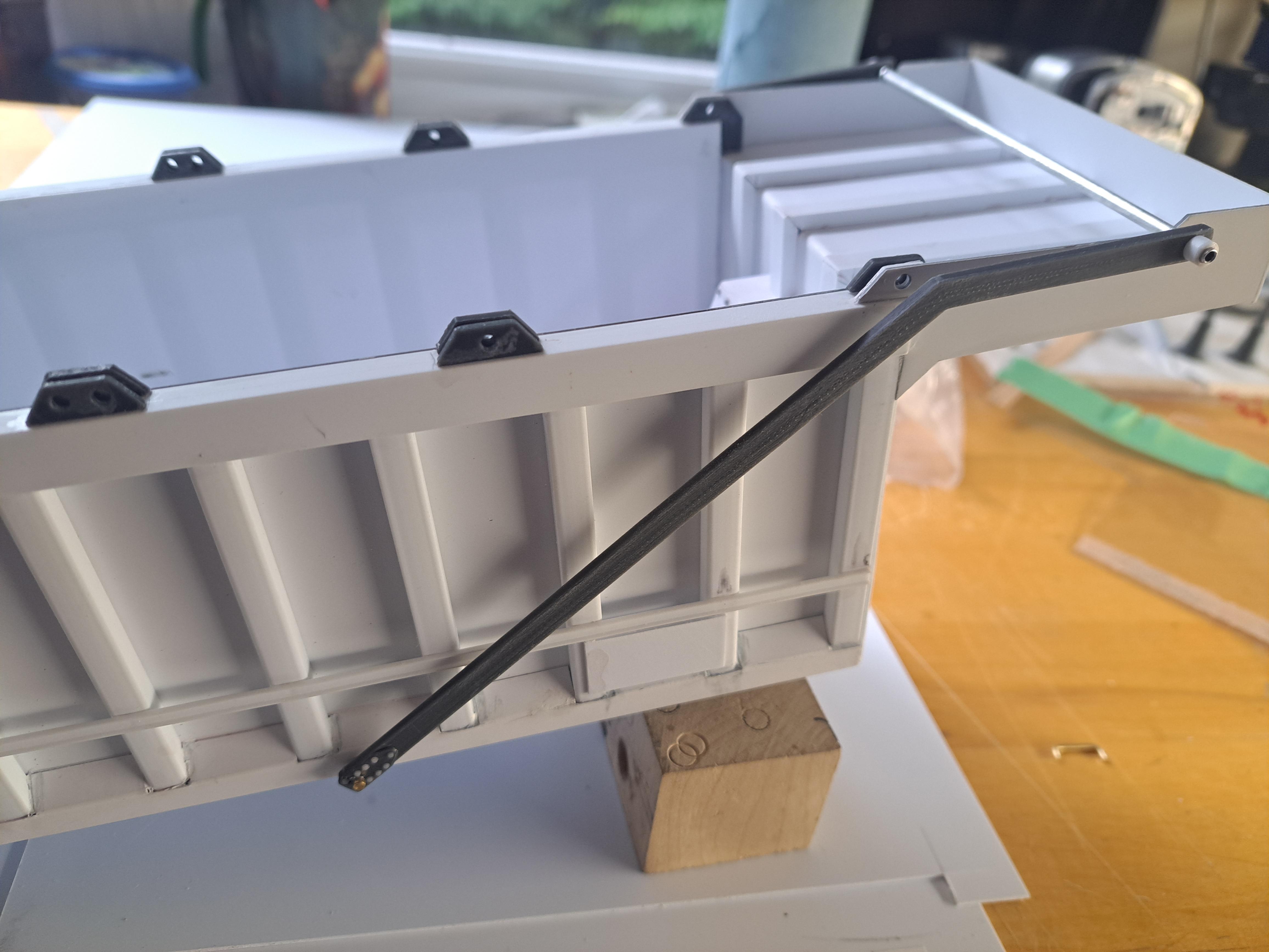
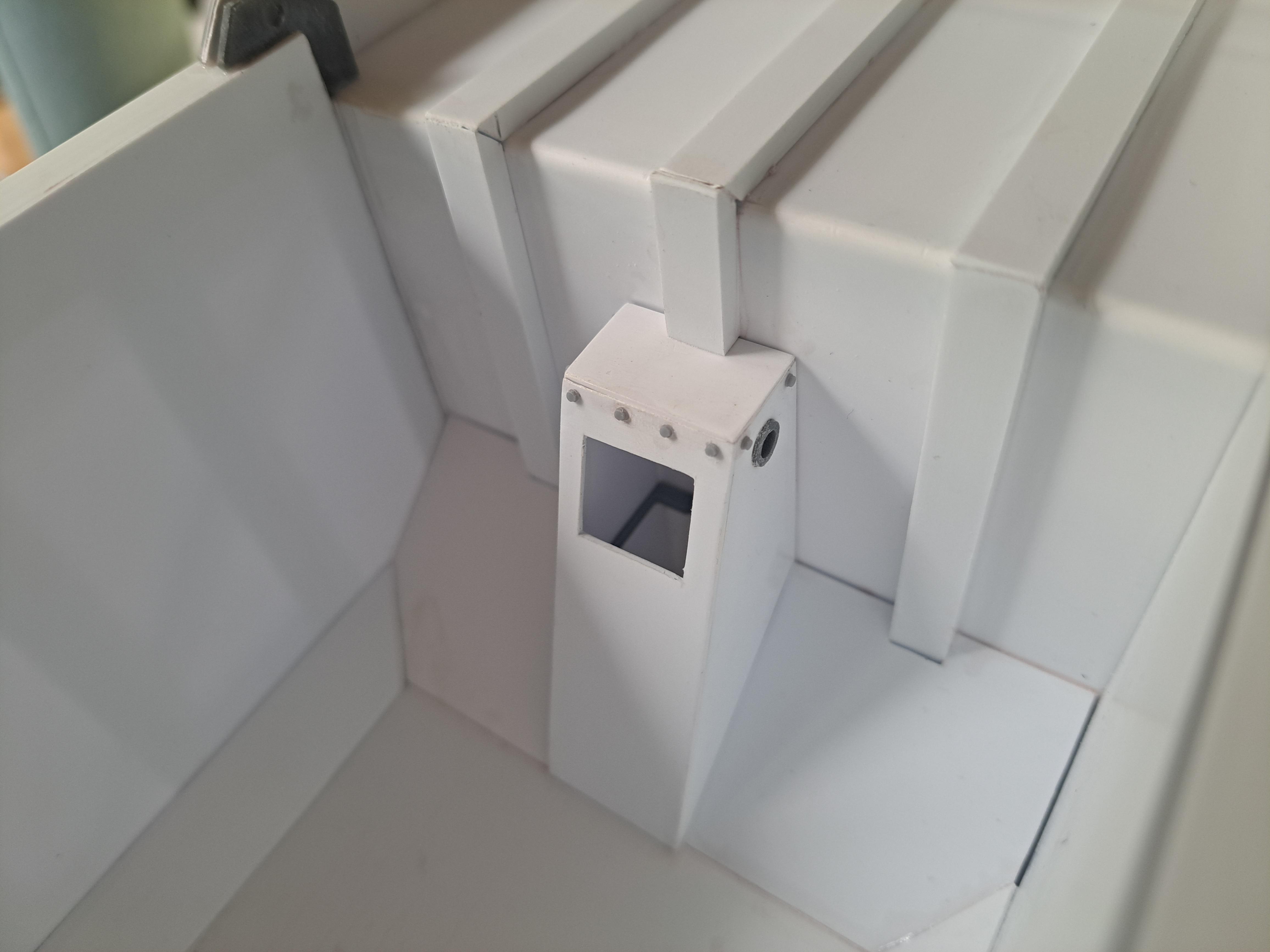
Almost done with this project, tail gate is done with locking pins, telescopic lift cylinder top anchor post done, front and rear mud flaps done, tarp arm done. All that is left to do is the telescopic cylinder. Here are some pictures. should be getting back to the Bentley soon.
-
Here are a few progress pictures
-
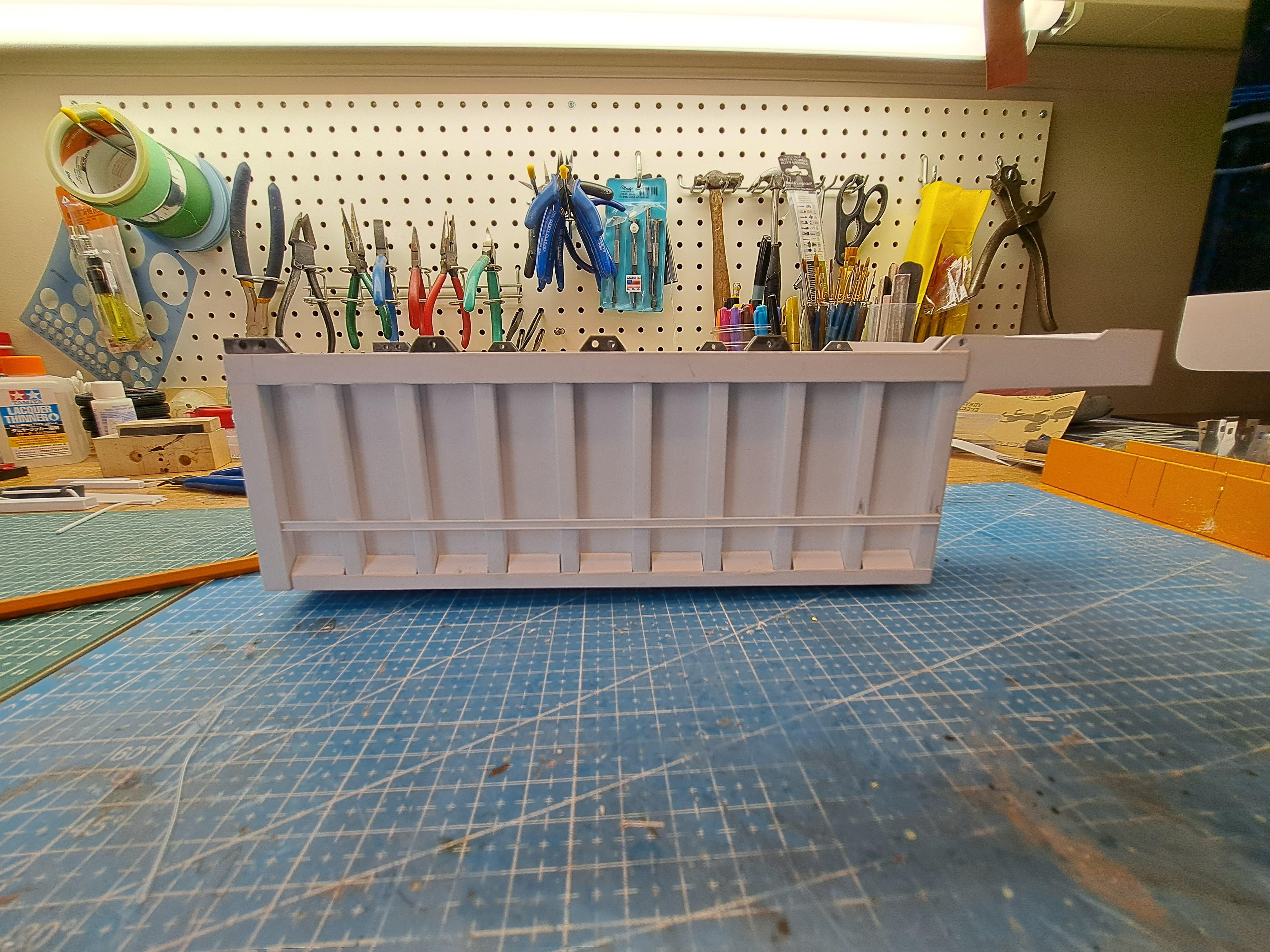
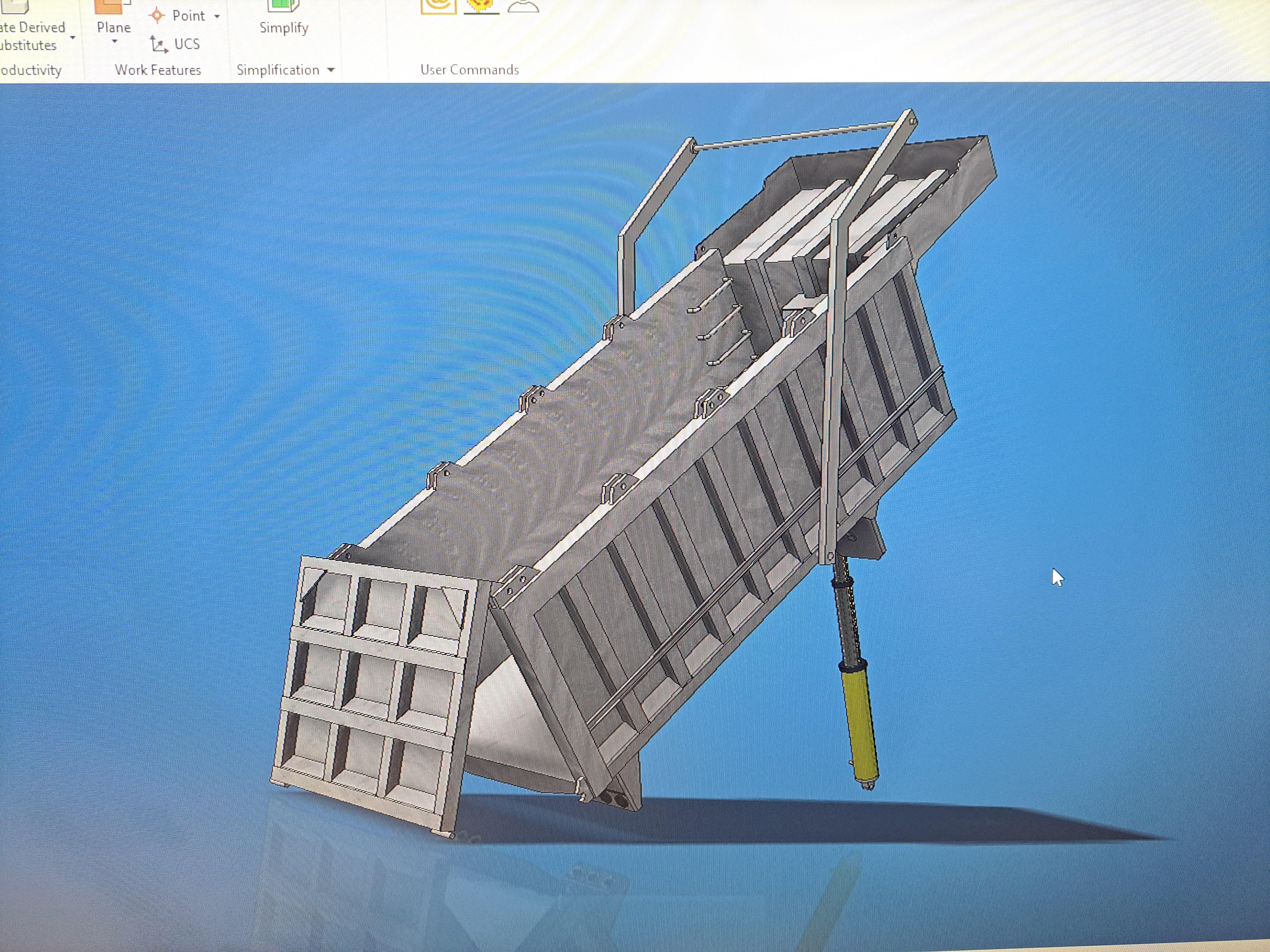
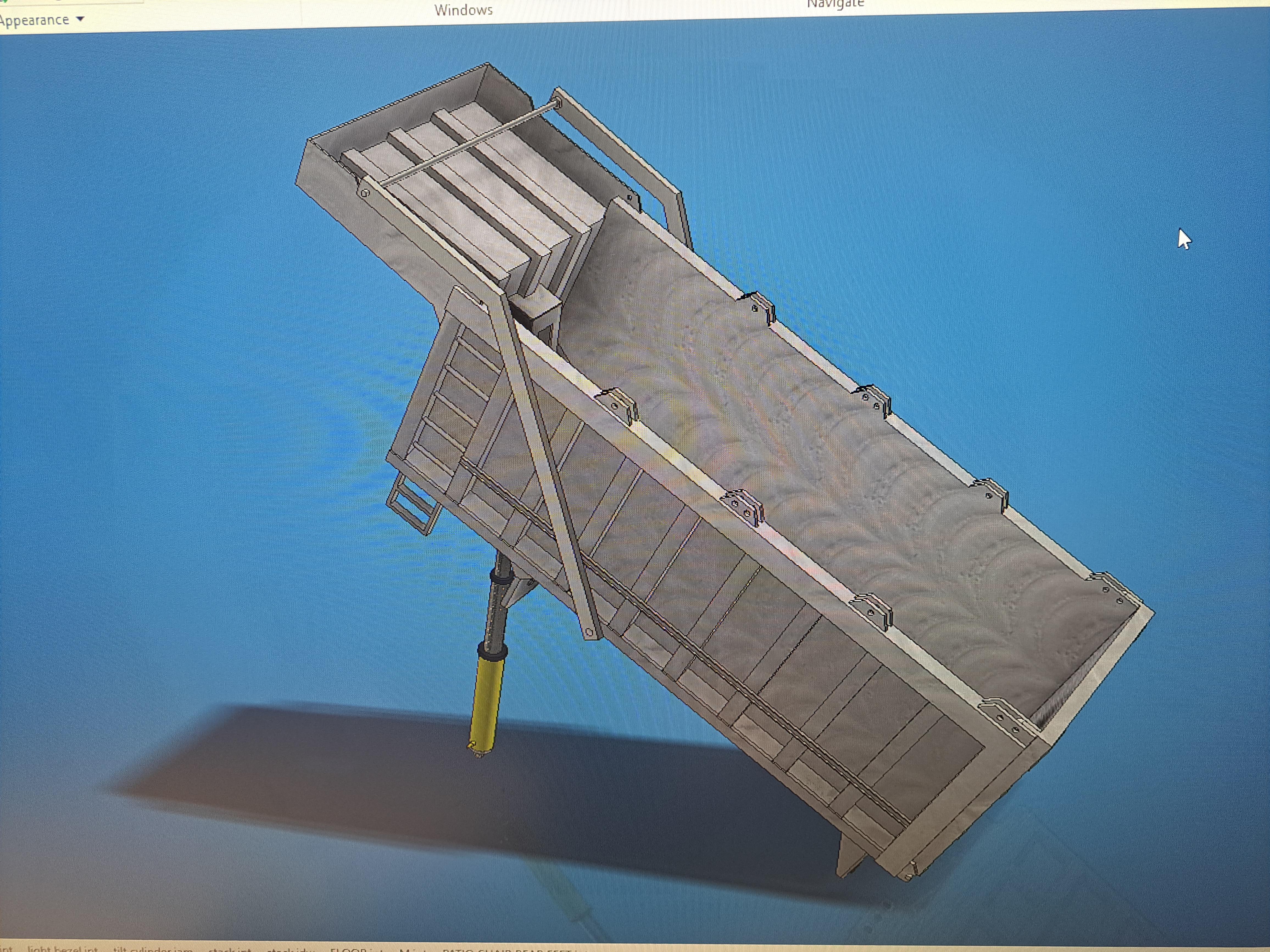
I'm currently working on my first 3Design Models projet (3DM for short). It's a dump truck body. I've completed the 3d modeling and will start the actual fab very soon. There is not much 3d printing in this projet, it will be mostly scratch built from styrene and aluminium. It will have a working tail gate and if all goes to plan, a working air driven lift cylinder. It gives an idea of what I can do. 3D model More to come.
-
Thank you both for that info, very interesting. That being said, since I'm not reproducing an old bentley blower that was built in 1930 but rather à 'new' old bentley built in 2020, I will stick with my goal and try (operative word here) to simulate the rexine that was employed on the continuation series car zero. It will certainly not be rexine, and it will not be any type of woven fabric. It as to be extremely thin, I guesstimate rexine to be around 1/16" thick. So at scale my material would have to be .005". And in order to conform to the very small radii and curves, it will have to be extremely flexible. These 2 criterias eliminate many choice. I'm still looking into the ultra thin neoprene. I'll also look into rc plane shrinkable covering and today I ordered a box of xlarge nitrile glove (thanks gbtr6) which is 6mil thick (close enough) and very flexible.
-
I'm affraid it would not be flexible enough. It needs to be as flexible as ultra thin latex but non degradable. The frame has multiple curves and very small radii. I'm stiil waiting to hear from the wetsuit guy that has 0.3mm thick neoprene.
-
If the plan was to simply paint the kit's body I would agree. But since I'm covering the open structured frame I did with a fabric, I really don't believe I can use paint. I think the final texture and color has to come from the fabric I will use.
-
Bugatti, I will certainly try and find some leather scraps as I will need it for the seats but I not convinced that leather would do for the body. First it would have to be very thin (under 0.015") and second, the Rexine has no grain at all. I'm not sur that leather can have no grain. Still, I'll look it up. Here's a shot of à Rexine coverded body where we can see that there is no grain to it.
-
A word about my body covering dilemma . I had found some very thin latex (party balloons) but someone from another forum mentionned that latex will degrade in a fearly short time so that's a no go. I'm looking at the option of using neoprene instead. I found a wetsuit fabricator who uses 0.3mm (.012") thick neoprene (apparently the thinnest available) which is exactly what I need. He's looking to see if he might have some cutoffs for me. If it works out my model will end up saying 'l'm Batman' . More to come on this.
-
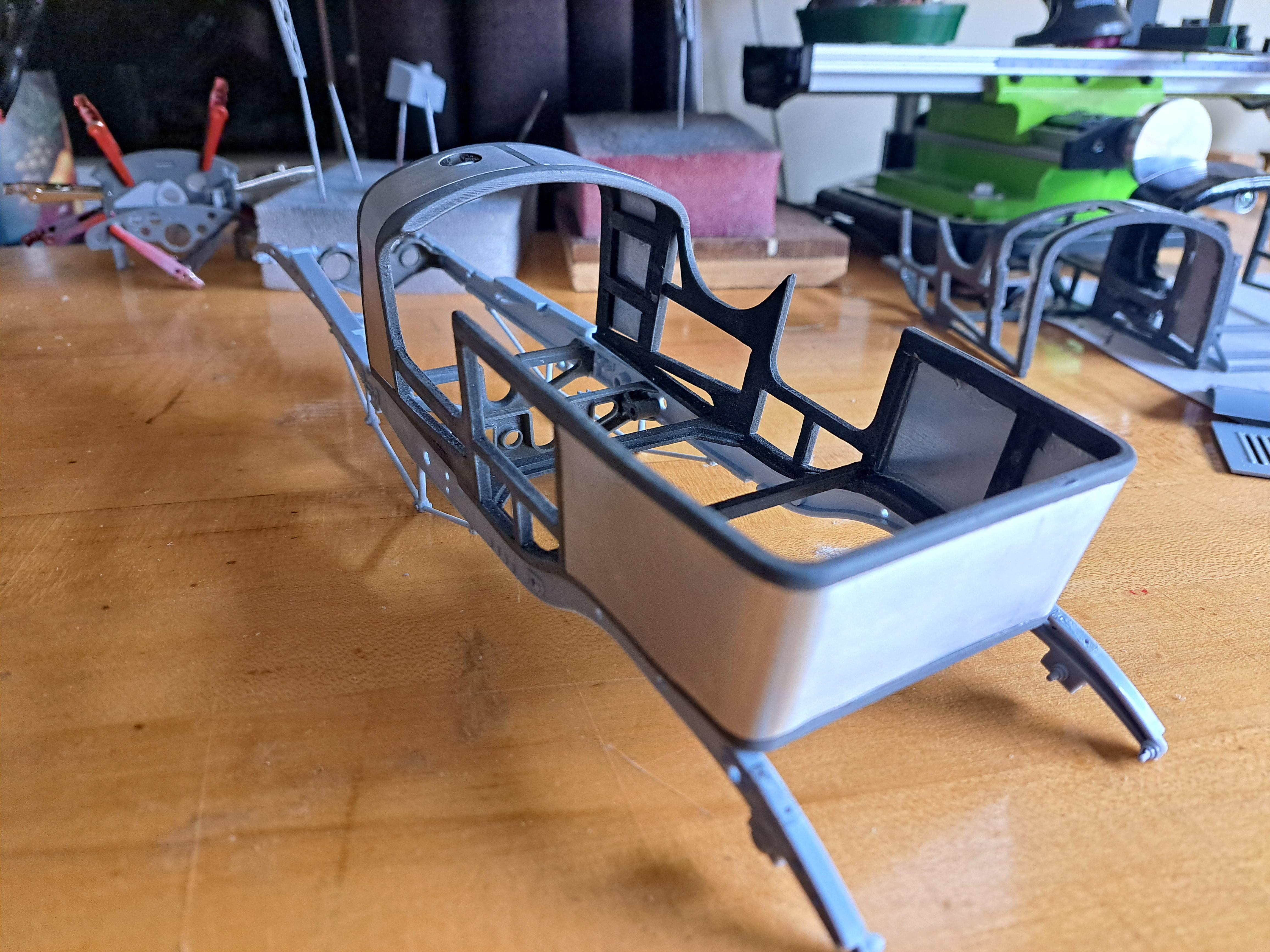
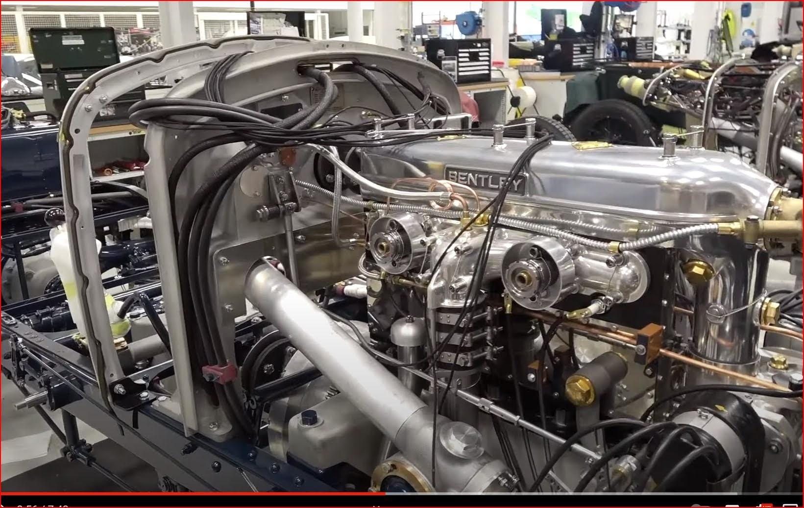
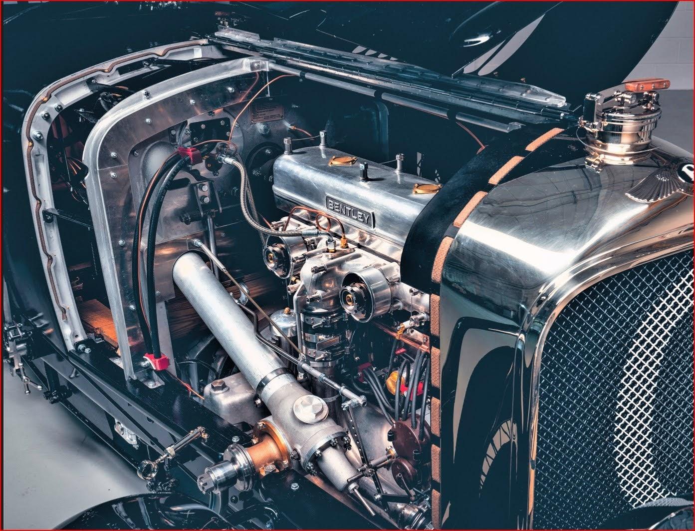
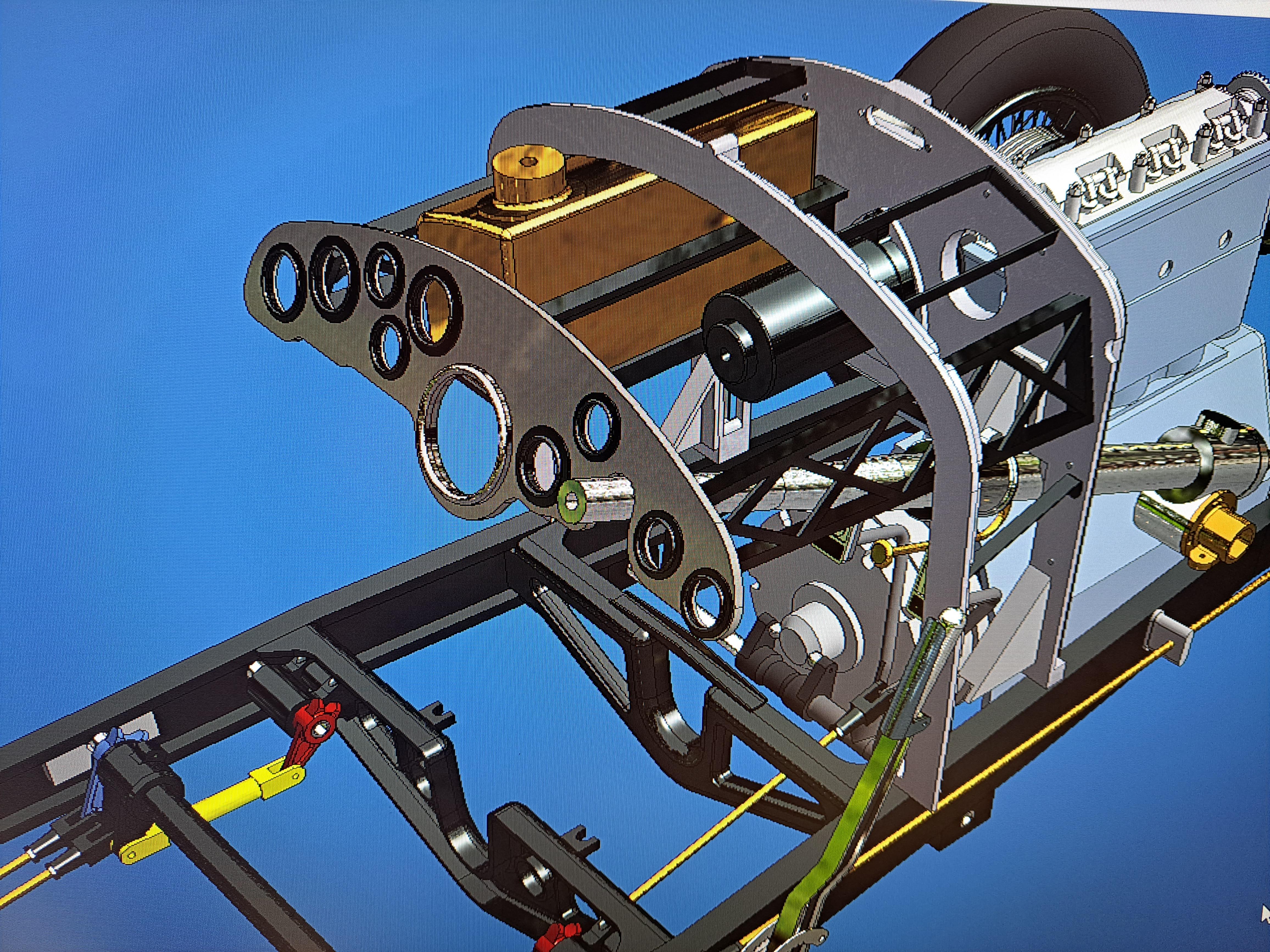
Pretty much completed the bulkhead assembly. I still have the gas pedal to do plus a few more wires to install but that will come later. And the real thing
-
Bonjour Pierre, Tu peux m'appeler si tu veux plus d'info. Suis-tu mon post sur la Bentley que je fais présentement ? Voici le lien au cas ou. http://www.modelcarsmag.com/forums/topic/181907-airfix-112-bentley-blower/page/6/#comment-2762377 514 947-4842
-
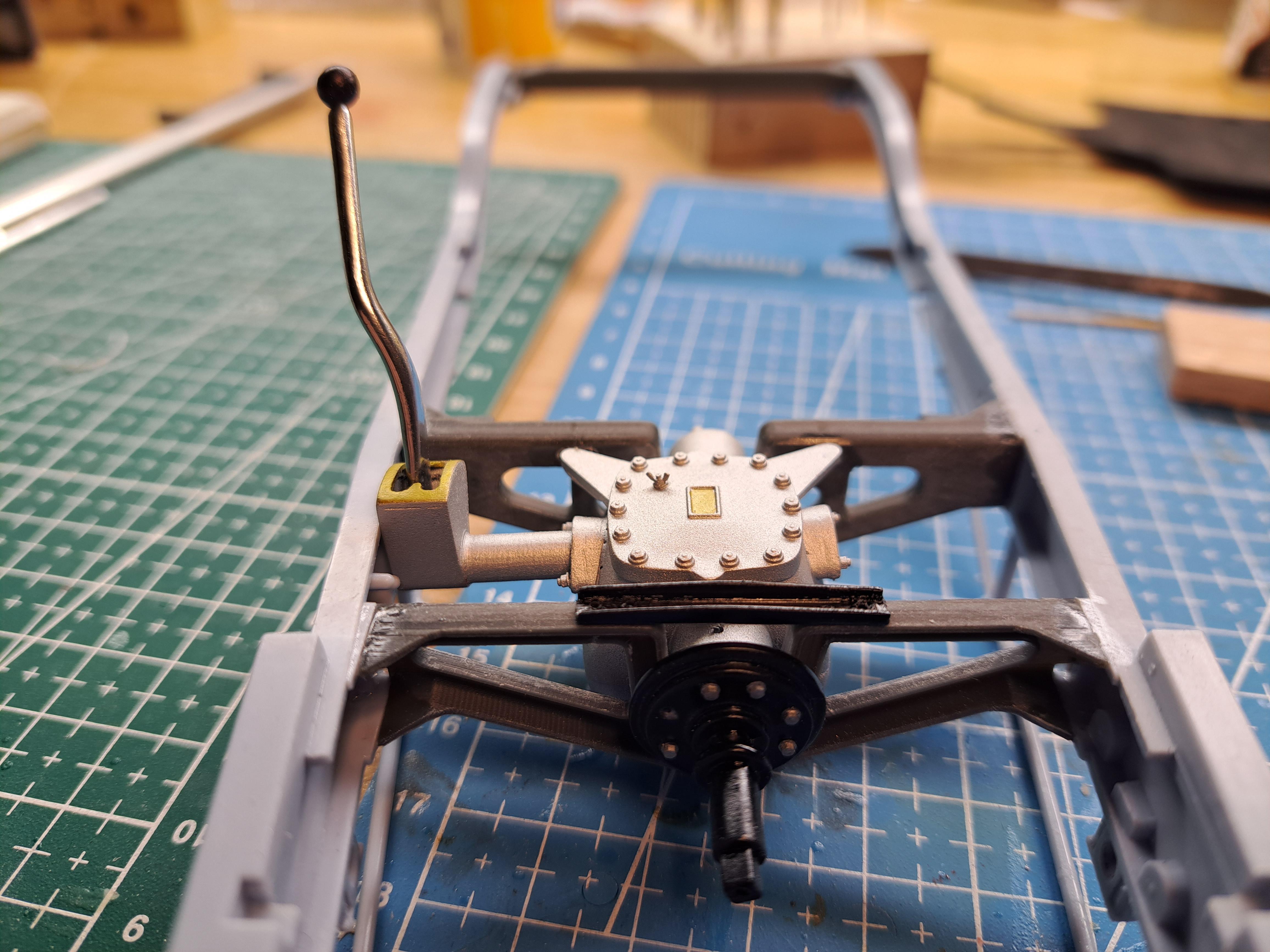
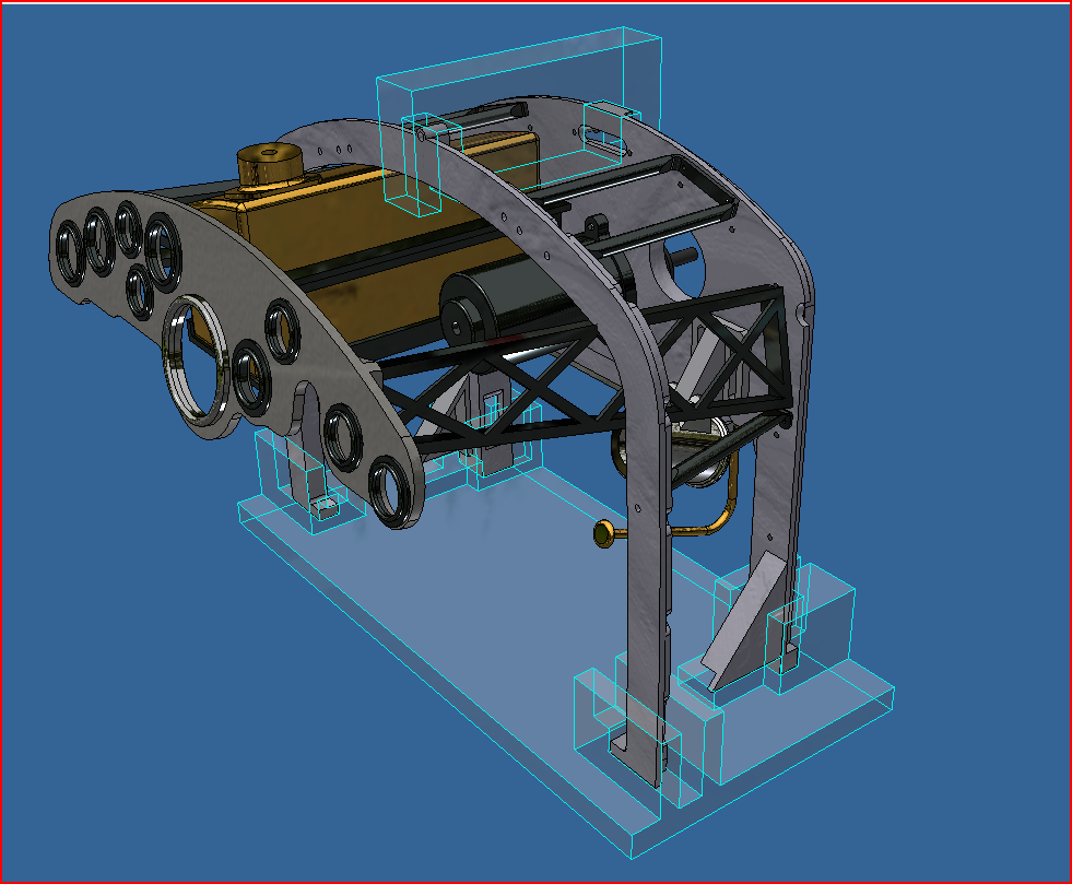
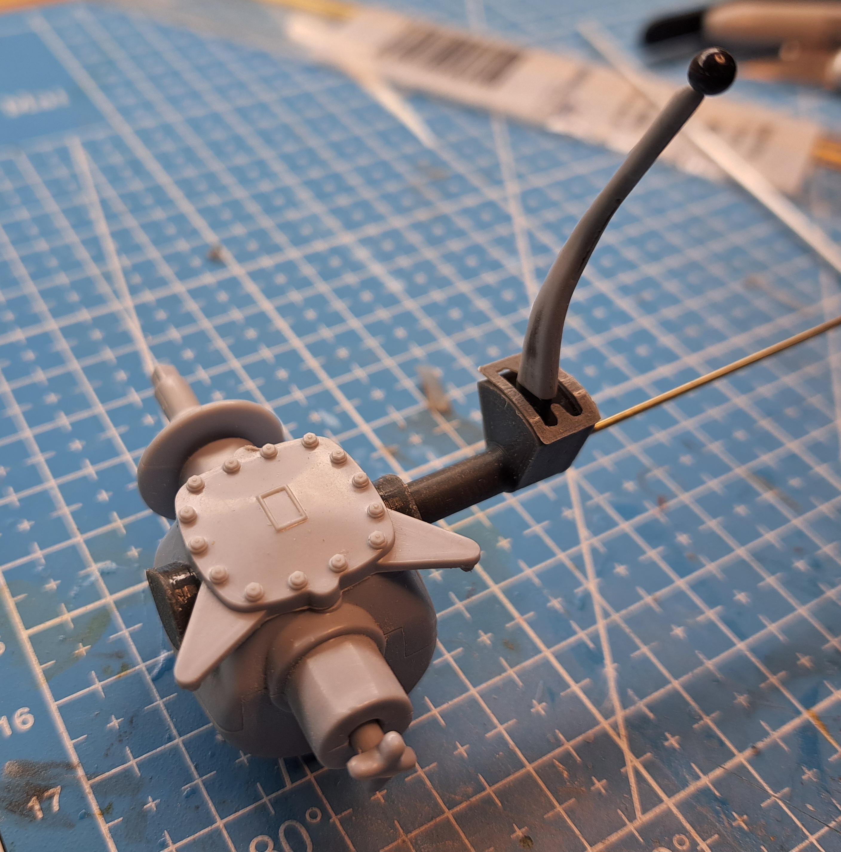
Completed the gearbox today. I'm not 100% satisfied with the shifter gate. Right now, it's painted to look like brass but I might try and make a real brass one. Espacialy since the gate and shifter are the only 2 things from the gearbox assy that are visible once the model is complet. 20230731_215821.mp4 l also printed a holding fixture to hold both bulkheads in relation while I glue some brackets in place. Here's the design (hi-lighted in blue) And the fixture in use I'm still scratching my head as to how l'll glue the latex covering on the body, it's getting clearer but I'm not quite there yet. I do know that I'll probably glue a thin felt between the body and the latex to give a little more volume and roundness to the latex.
-
Hello all, Having much more time these days, I've decided to start a small business venture. I'm offering you my 30 plus years experience in design. You would like to add some custom details to your model? Or maybe you need a specific assembly or fabrication jig? I can model them for you and generate a .stl file so you can have it printed. Can't print it yourself ? I can print it for you. Whatever your need, we can discuss it and see if I can help you. Prices will be based on complexity, precision of print and quantity. Here is an exemple of what can be 3d modeled. And printed Here is my info (Sorry but the web site is not up running yet). Hoping to do some modeling with you!! François
-
After several unsuccessful tries at removing the airfix chrome, I finally found the right product. It's ferric chloride, and this stuff is nasty. Gloves, goggles and a mask are a must. But after about 30 to 60 sec , the chrome is off and about another 2min to remove the copper. And yes, there is copper under the airfix chrome because unlike other kits, and despite what others may say, the chromed parts on the airfix bentley are actually chrome, not paint, and not an aluminium deposit. The process is similar to chroming a metal part except that the copper layer is applied via an electroless process since plastic is not conductive. Once the copper is there, the chrome can be applied thru a normal electro plating process. This producess a very hard chrome which is why it can not be scrapped or sanded off without serious damage to the part itself. I tested Revell's chrome paint on the gear shifter and, althought very pricey at around 35$ canadian, the result is very surprising and extremely simple. No black primer, no clear. Just spray and let dry for 48 hrs. I'll never fuss with Alclad products again. Here's the shifter before and after the chrome paint.
-
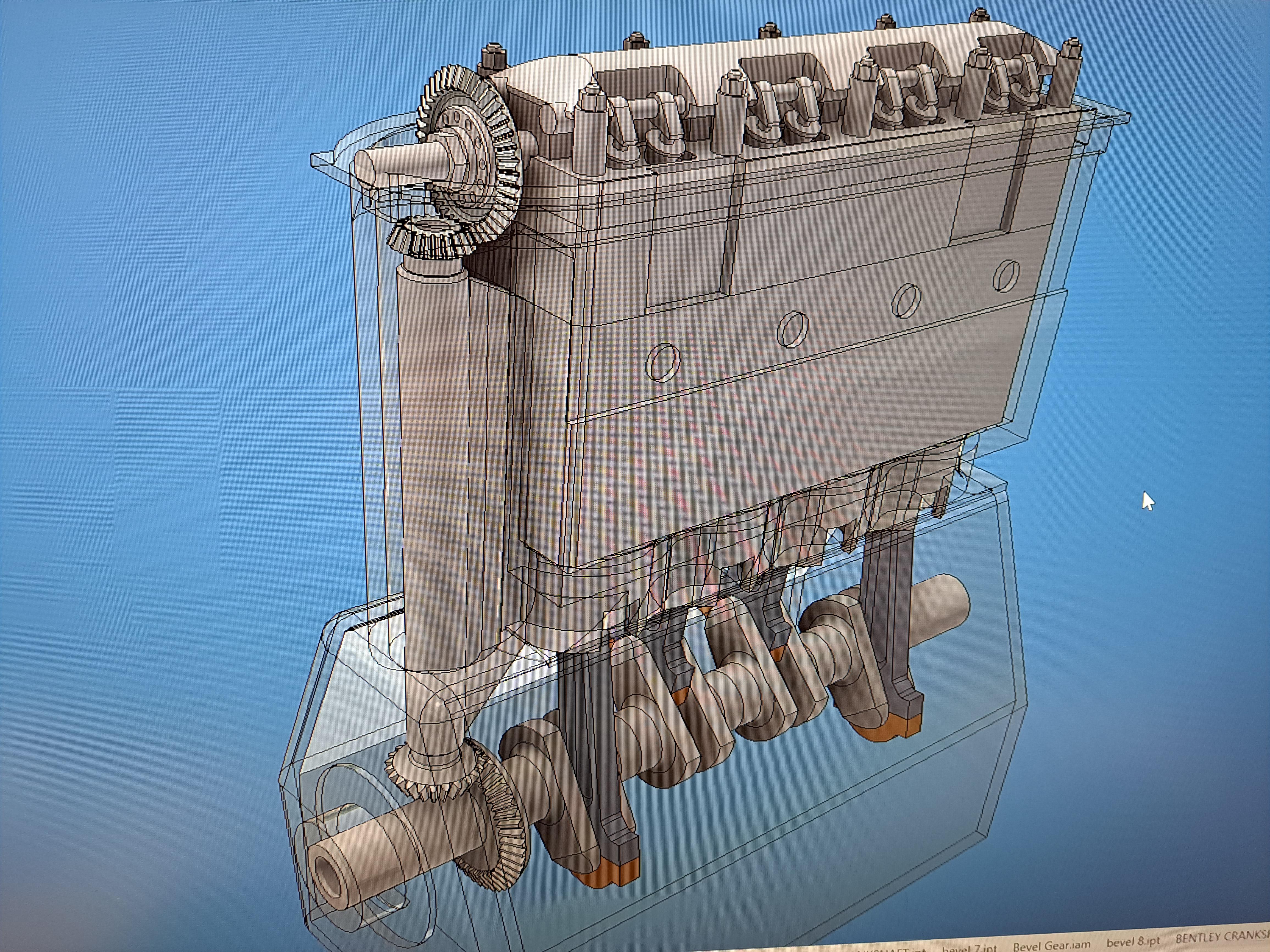
Finaly got the body framework completed and added the aluminium sheets. I found what I think could be a good alternative to the different materials l've been testing to wrap the body with. I was looking for a latex sheet but couldn't find any so I bought a large latex party balloon. It won't be easy but I think it could work. It's not as shiny as I would like but I'll get some latex shine to buff it up once all glued on. Next I tackled the gearbox. The one provided with the kit is pretty good. But the side extension for the shifter is non existing. The kit's shifter is simply glued to the floor. That won't do since I'm doing redo the floor out of wood as should be and I really want a moving shifter with a 4 position gate. Here what it should look like. Here's what I've done so far I had to modify the shaft going thru the gearbox t9o accomodate the shifter extension