François
-
Posts
489 -
Joined
-
Last visited
Content Type
Profiles
Forums
Events
Gallery
Everything posted by François
-
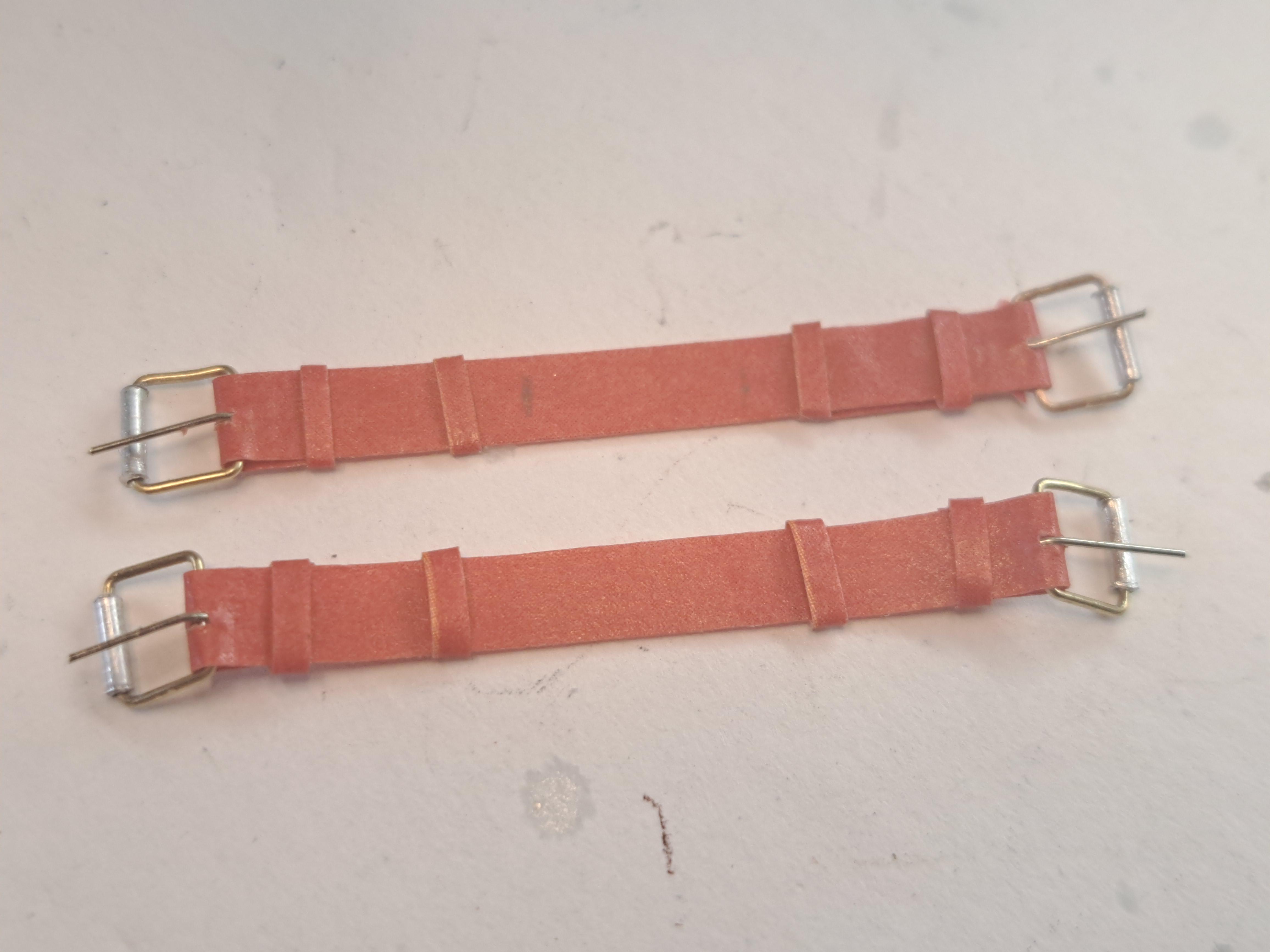
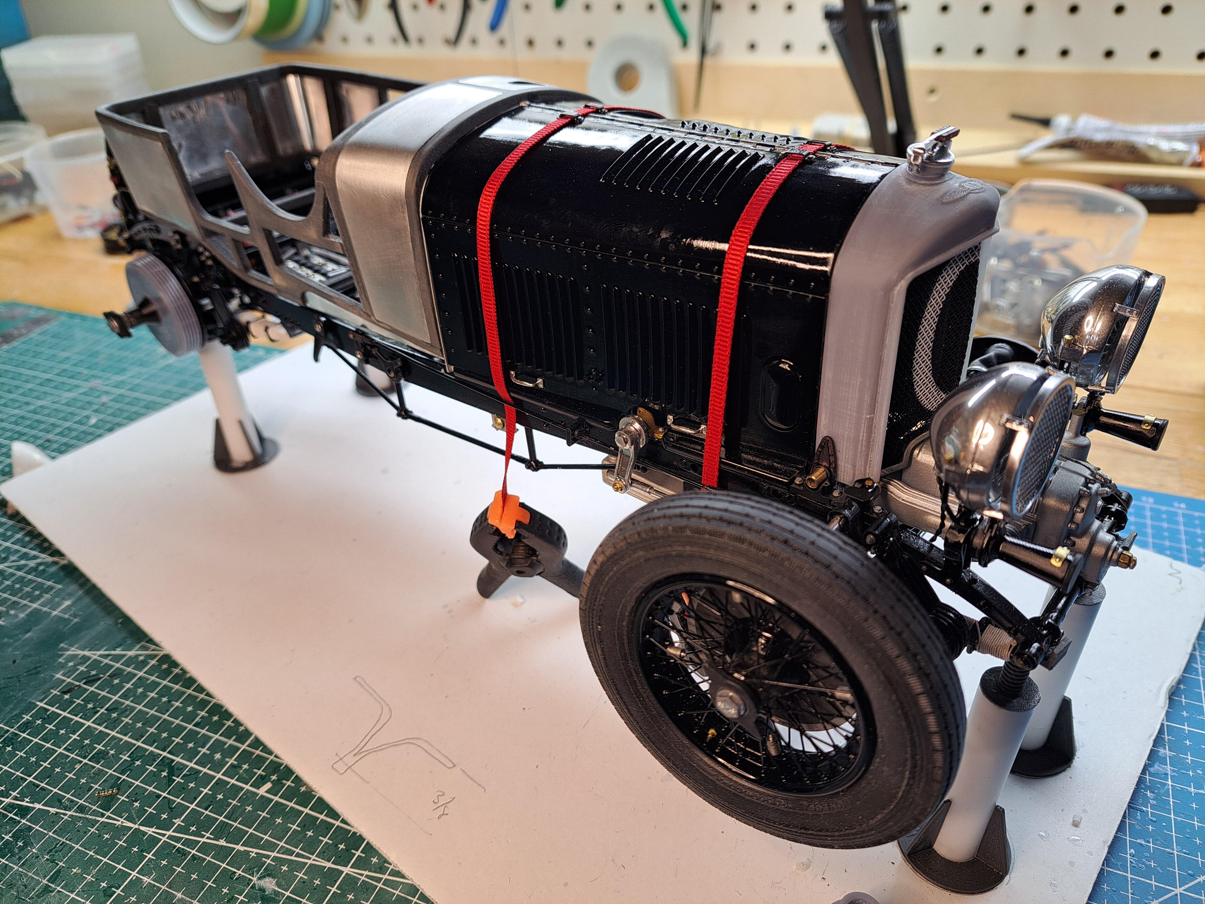
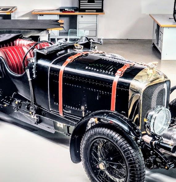
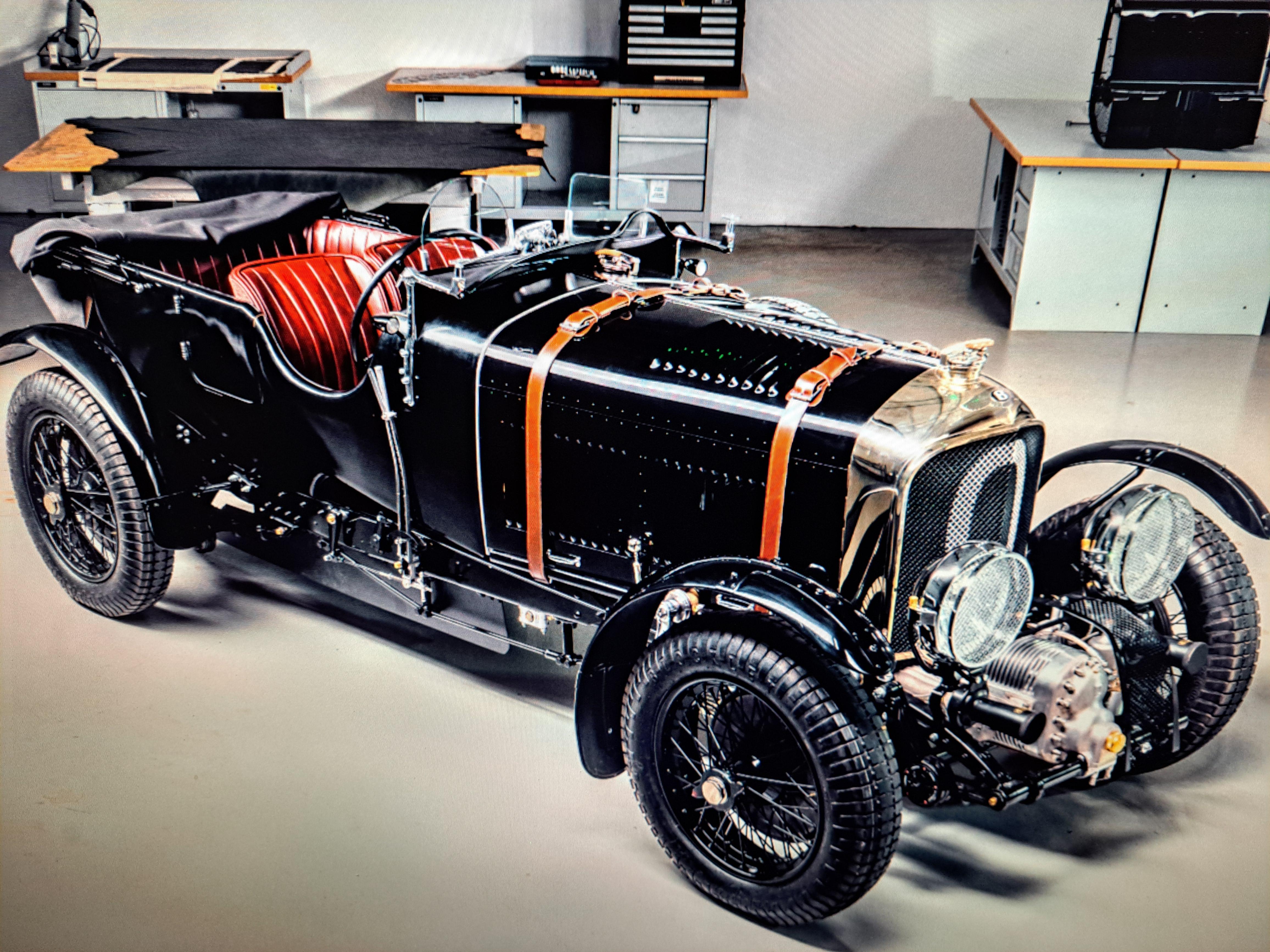
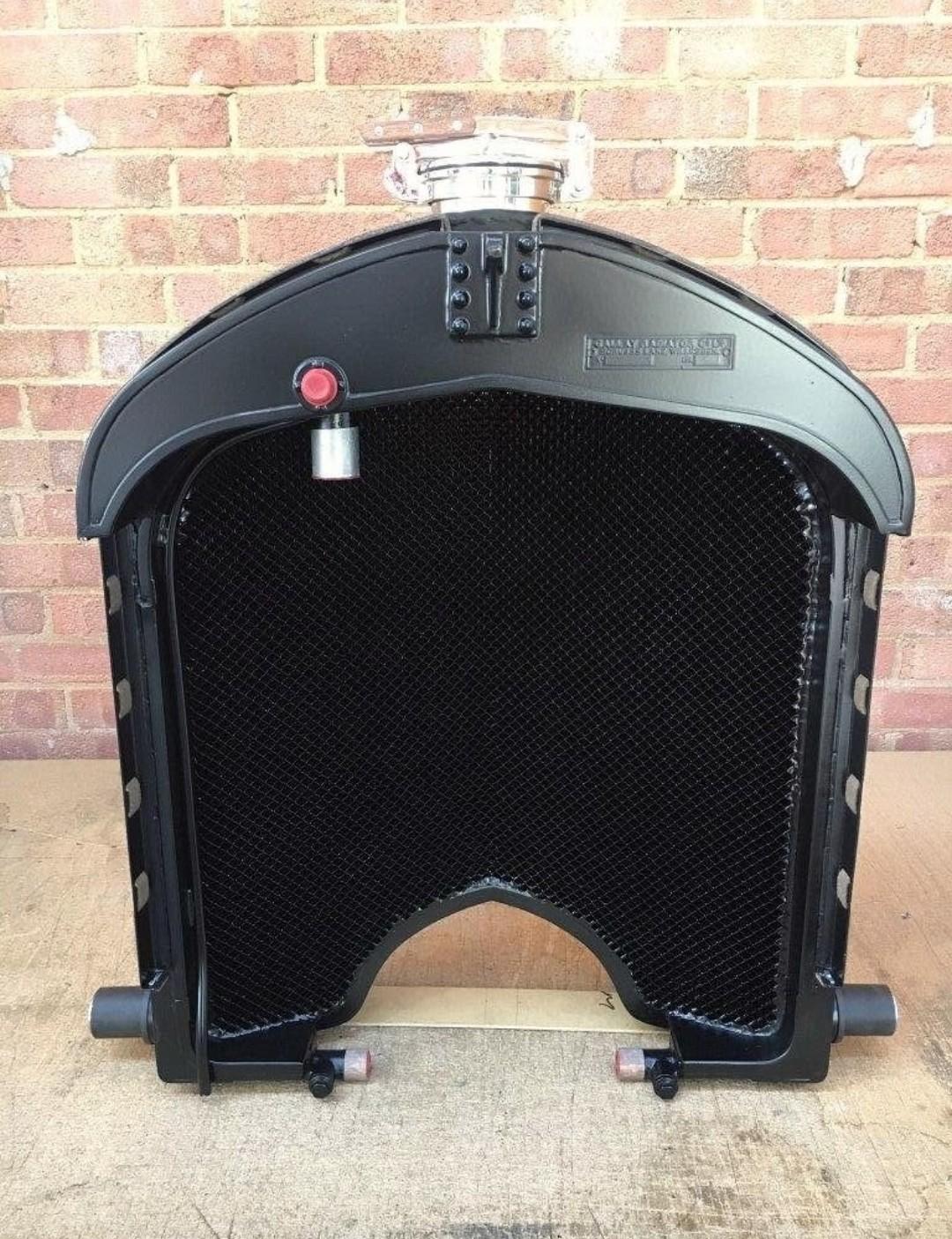
There's a saying that goes like this " Third time's a charm"... Well in the case of the radiator cover, it's the fifth that charmed me!! I finally got the chrome right! Now, all I have to do is install the front grill whitout damaging the chrome... yeah right... Installed the hood clamps (I'm using a dummy hood while a new coat of paint dries on the good one). 20240213_165816.mp4 Started work on the hood straps, made tiny buckels and the 2 top straps are done. This is what the kit provides (black rubber)

-
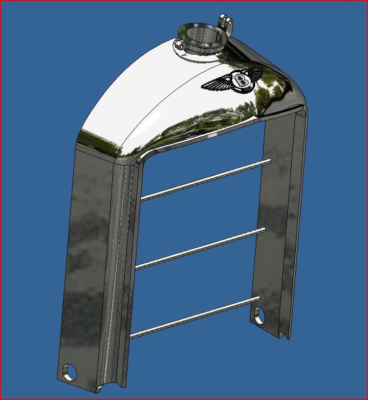
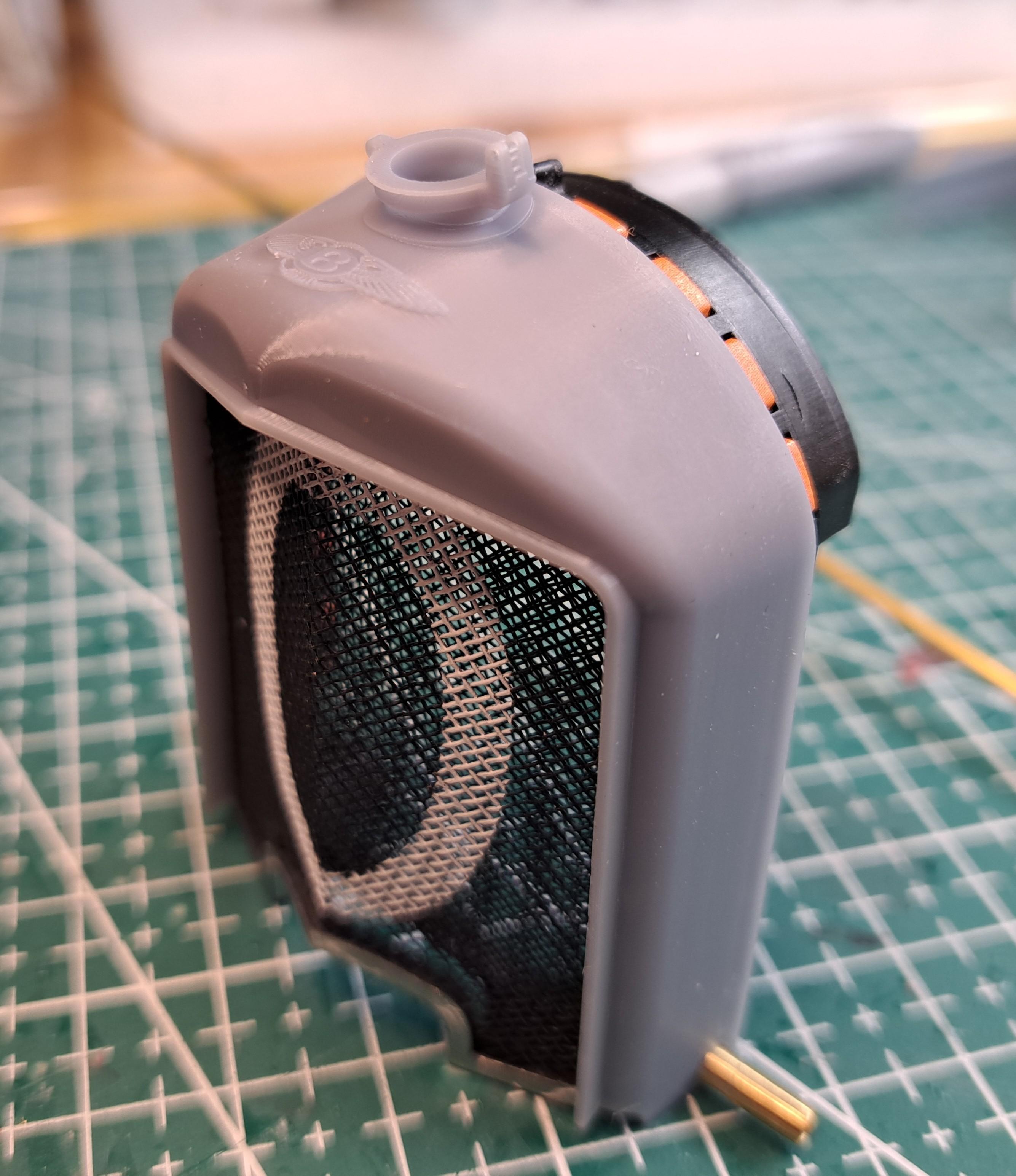
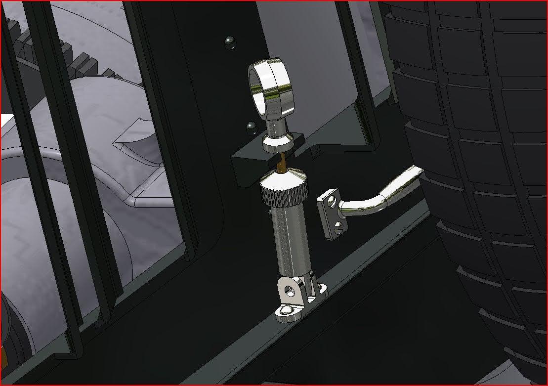
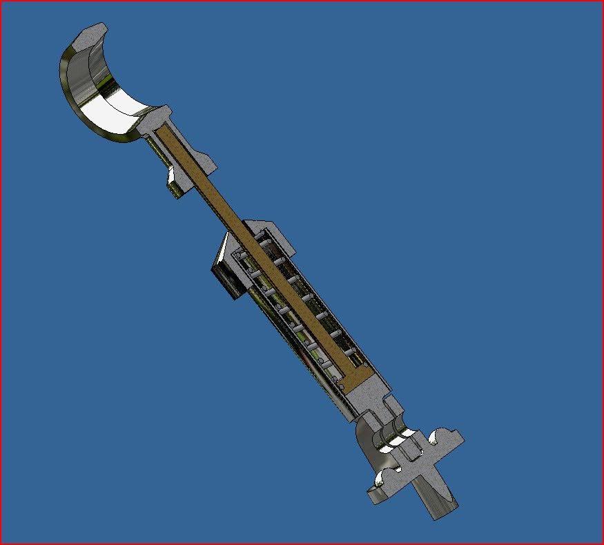
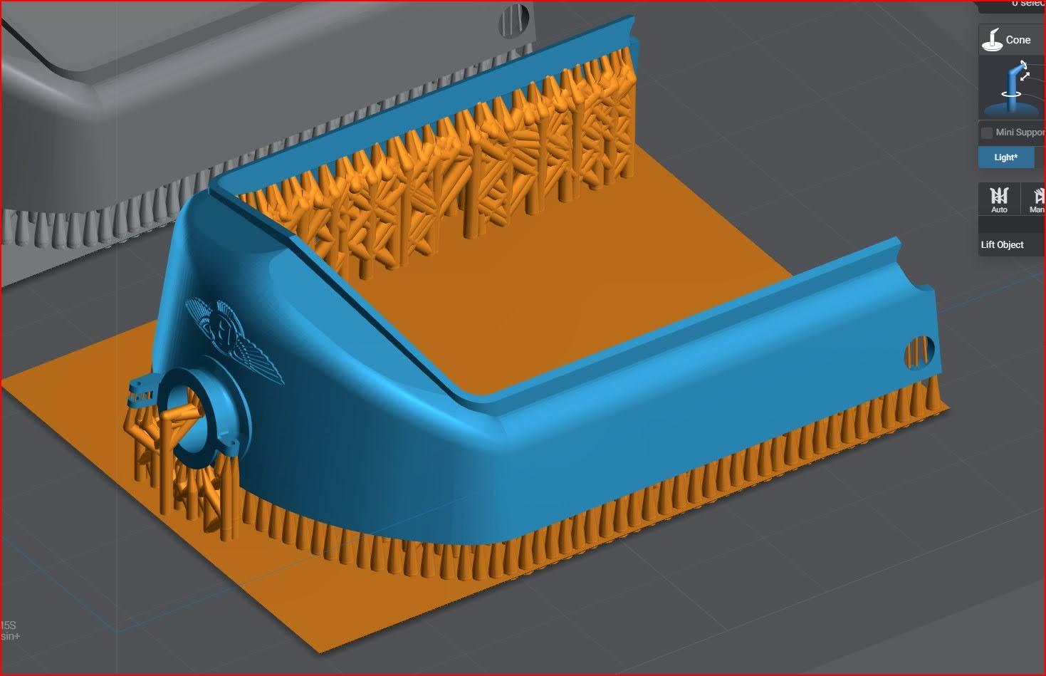
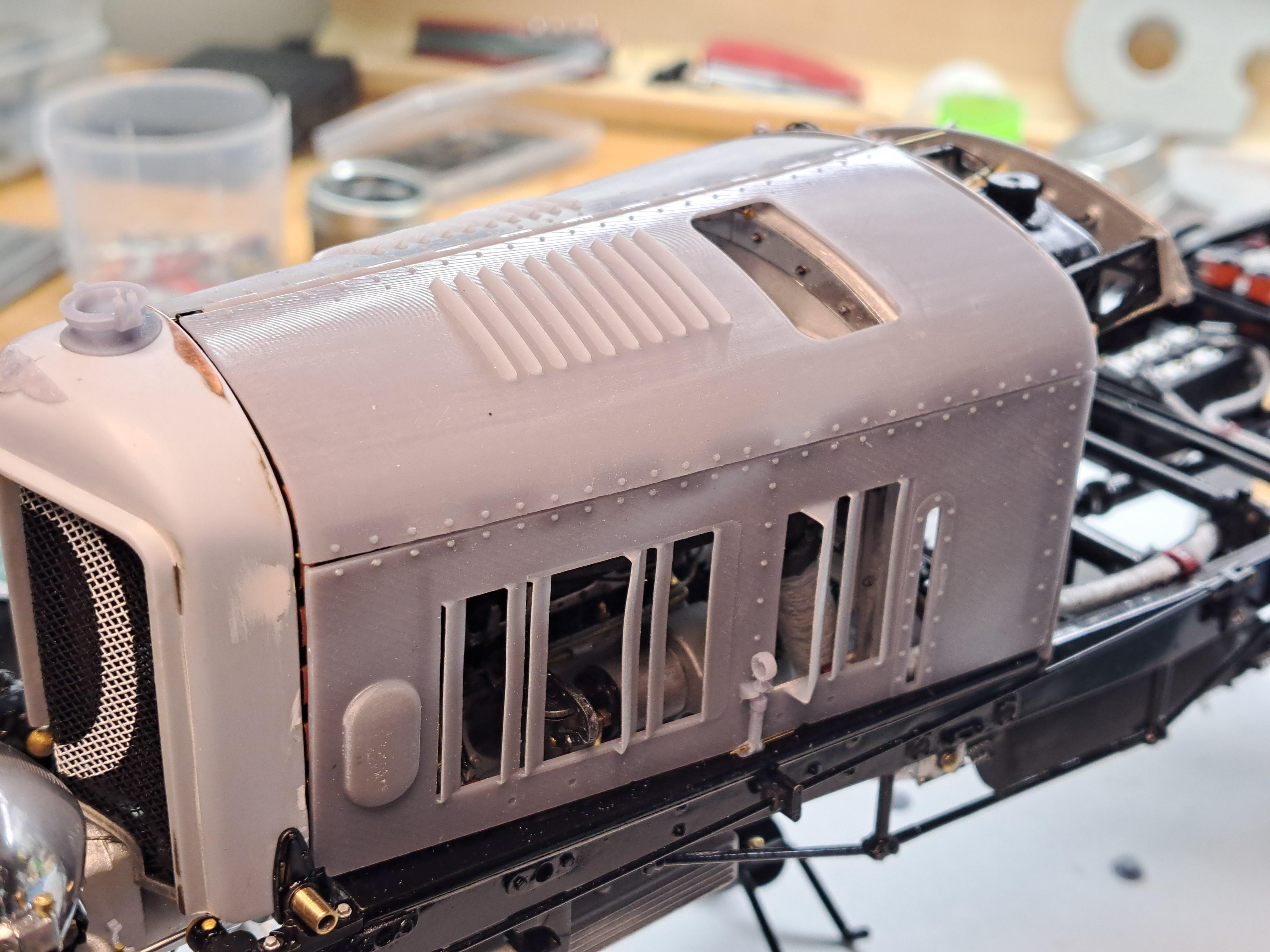
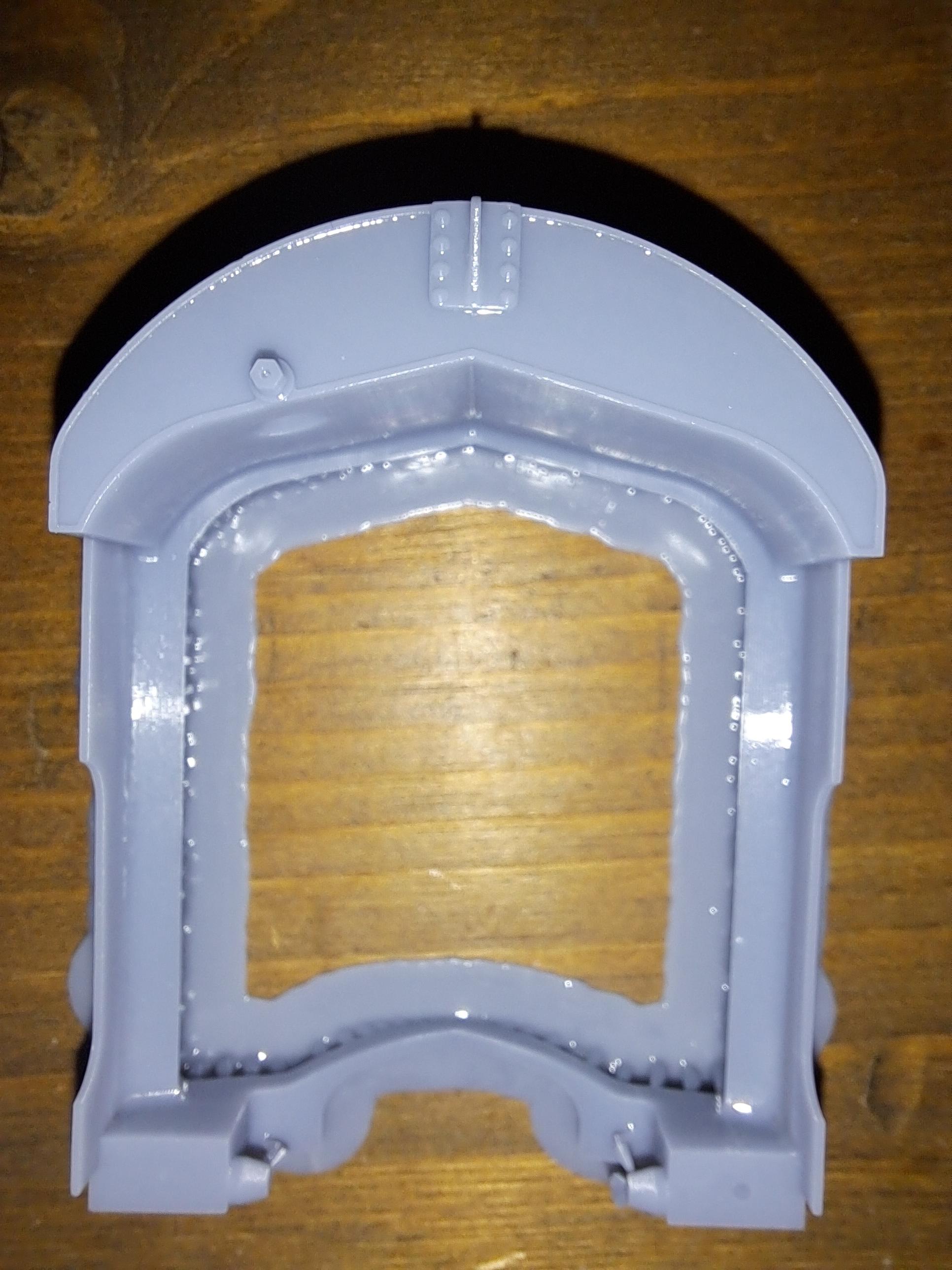
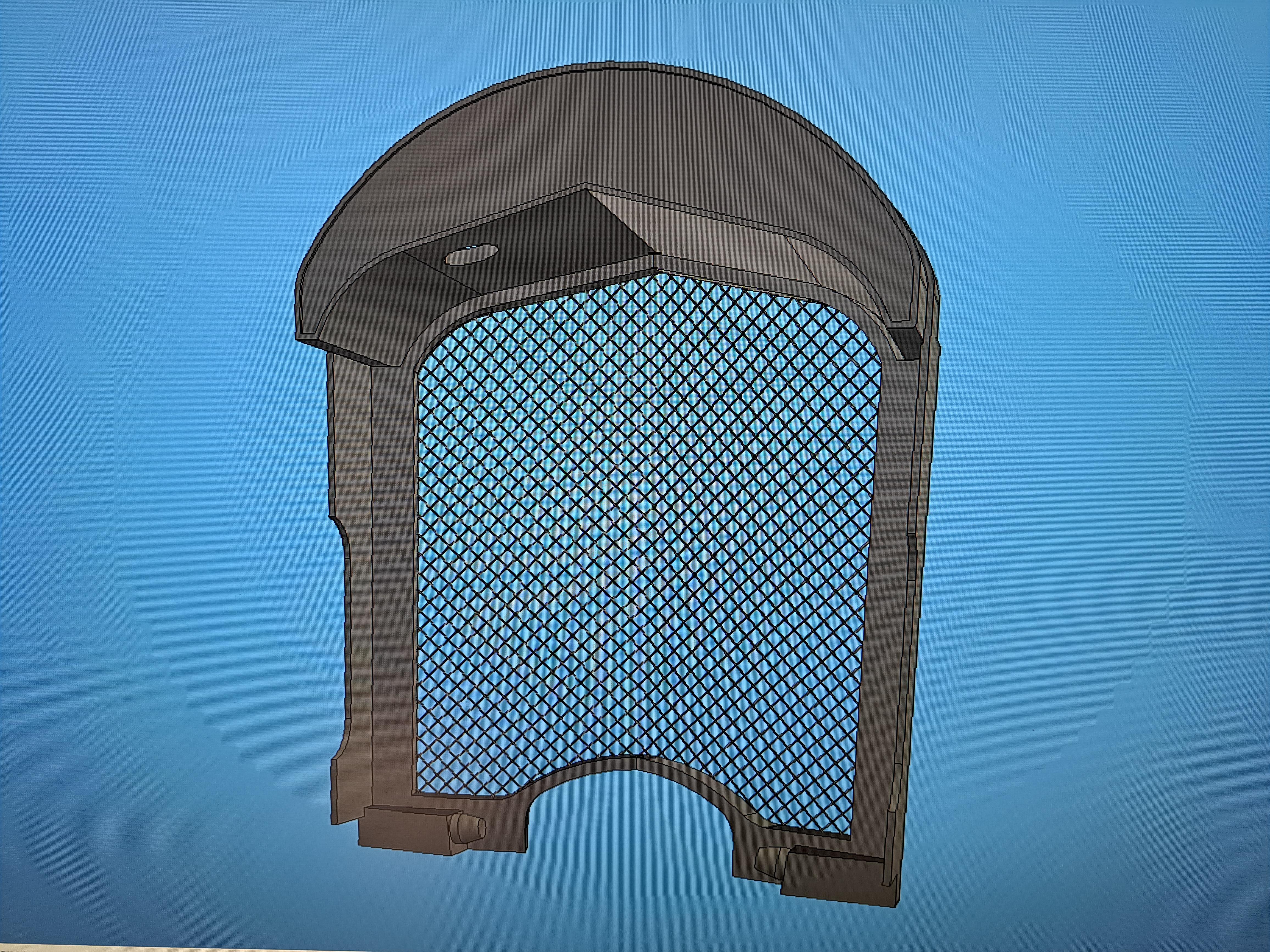
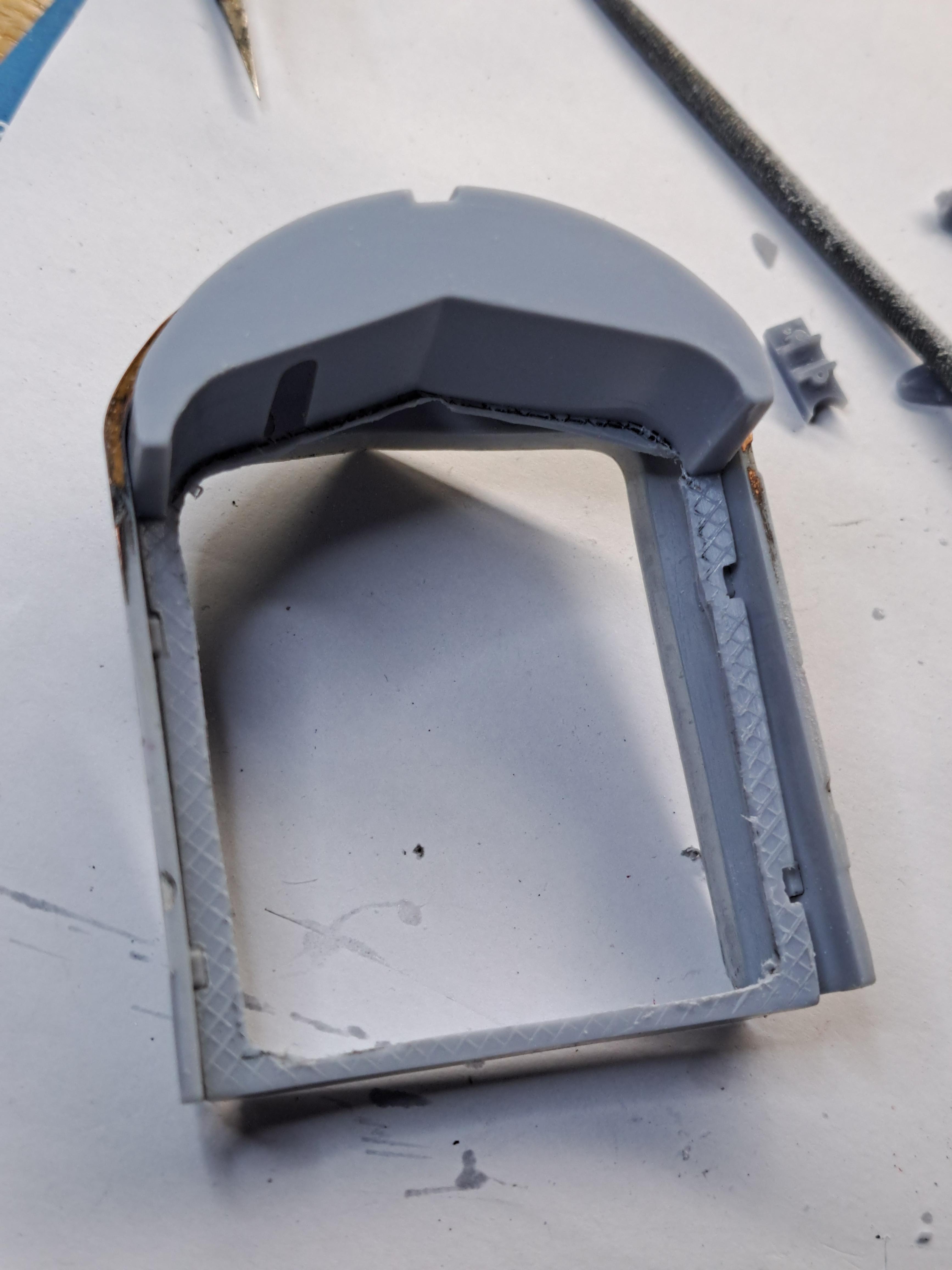
I printed the new radiator cover. I incorporated the bottom trim directly instead of being on a separate part. That way, I'll be able to directly fit the front grill inside the cover. Here's the newest version. I also made the 2 hood clamps, they are actually spring loaded and somewhat functional. Exploded view of a clamp Both clamps assembled Test fit on the model
-
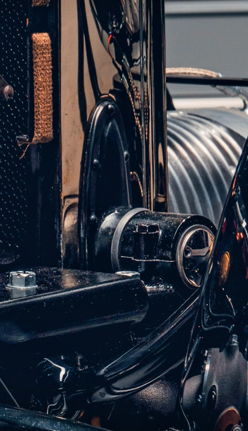
Not water based but yes, available and at different duro. It's quit expensive so I'll have to be 100% sure of the design before printing with it. Being seldom satisfied with what I do right off the bat, I modified the radiator cover to better reflect the reality. The nose radius was too small. Before After The reality
-
It took a few tries but I think I got the new radiator cover right. Now all I need to do is to chrome it (gulp!!). Good thing I made 2... Here are some shots. Before sanding After sanding And again, model vs real car
-
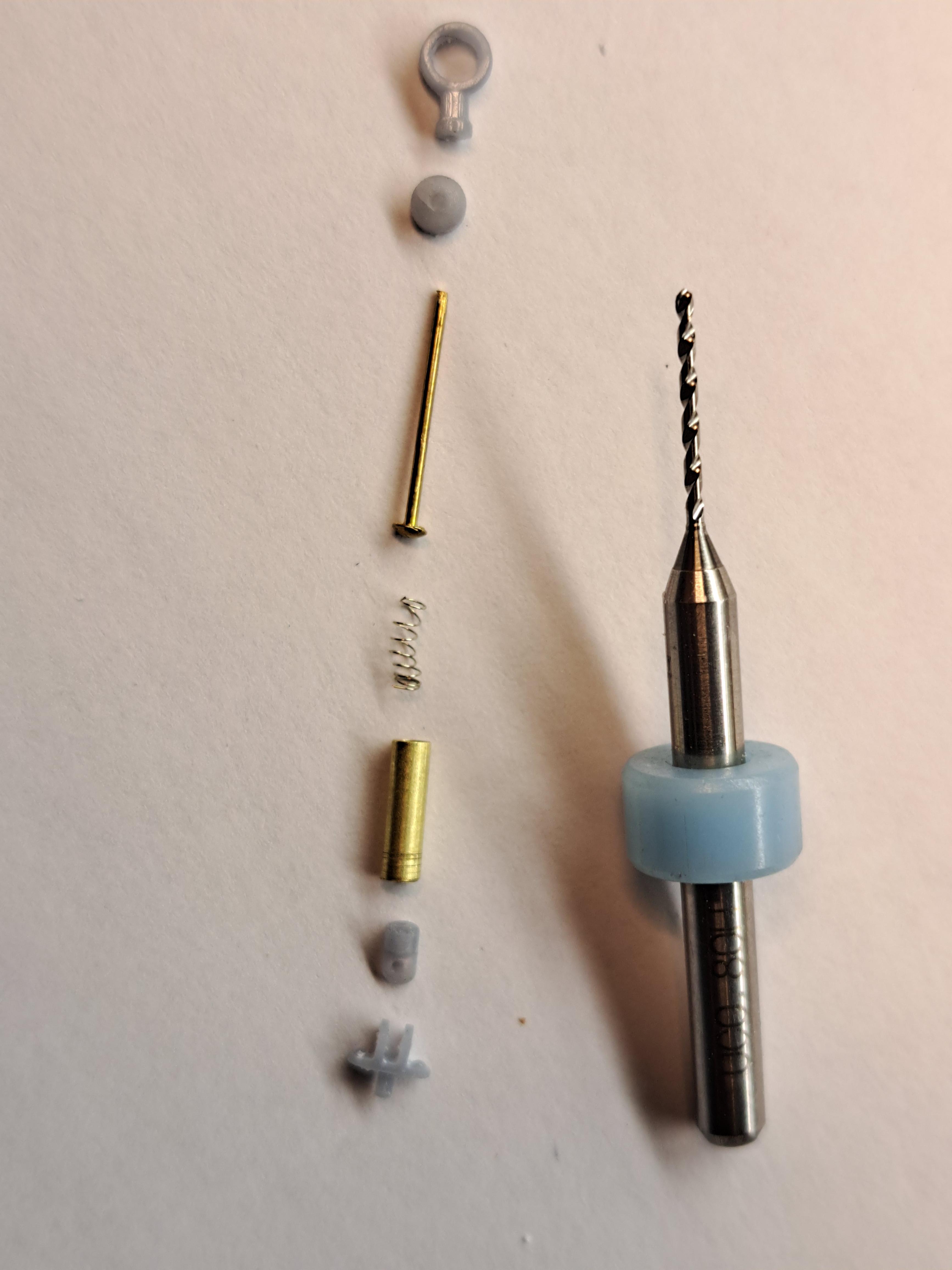
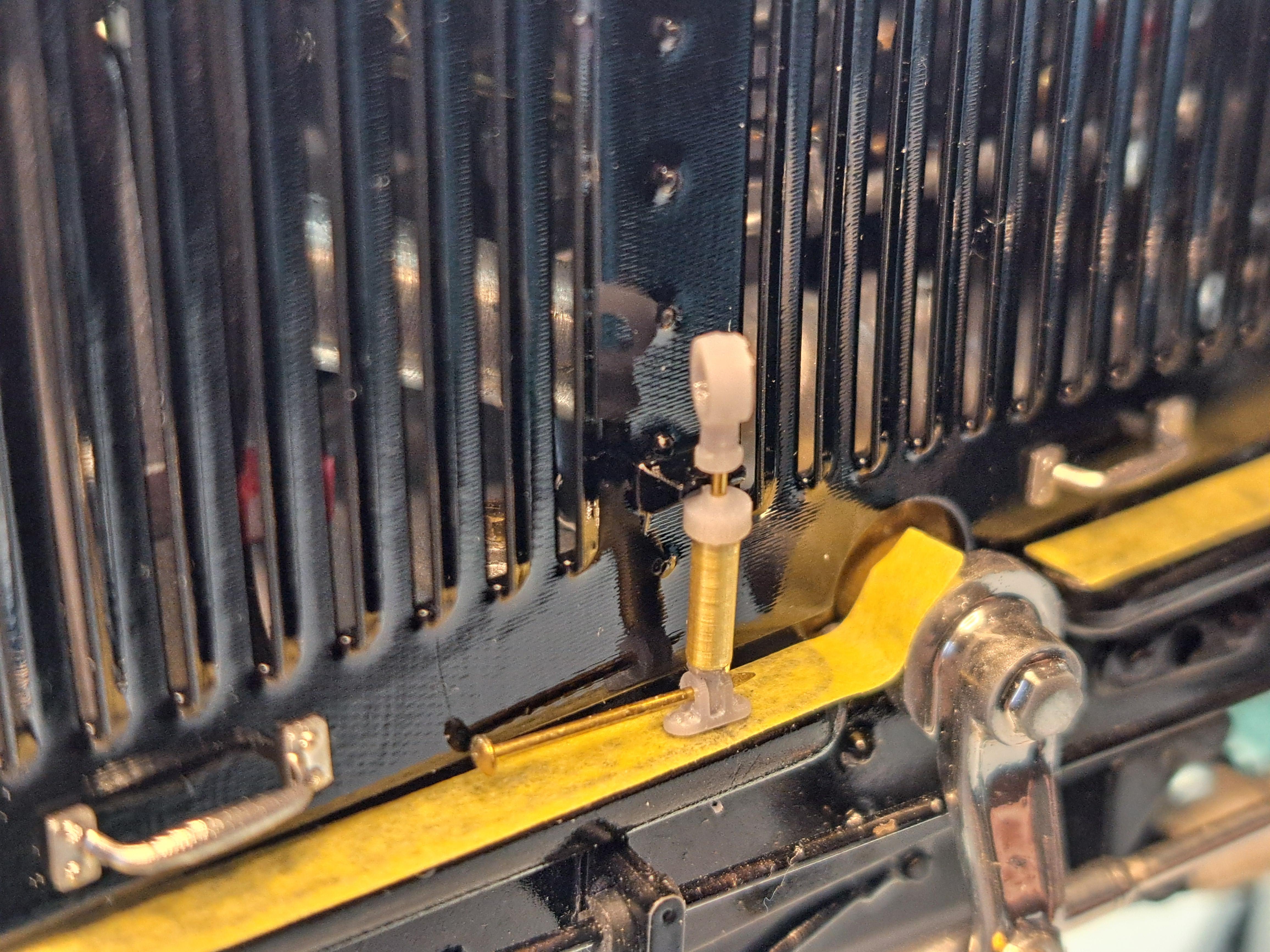
Well, I really messed up this morning. I didn't like the chrome on the radiator so I tried to remove it. By doing so, I sorta melted the plastic, the part is now unsusable. I spent many hours modeling the radiator cover and it is printing as I write this. I modeled a working hood latch. It consists of a tiny spring loaded cylinder with a finger ring at the of the piston rod. This thing is micro. I'll have to fabricate a .05in od compression spring. I'm using a small brass nail for the rod (leftovers from a wooden ship build) The real one
-
All 4 hood panels are painted, I should be able to install then along with the radiator next.
-
Thanks absmiami I just painted the radiator cover, not sure it's ok yet, I'll let it dry first. I also started painting the 4 hood panels, still some sanding to do before the black finish.
-
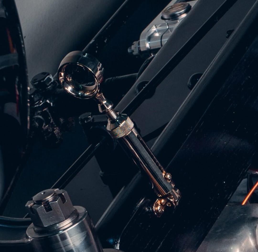
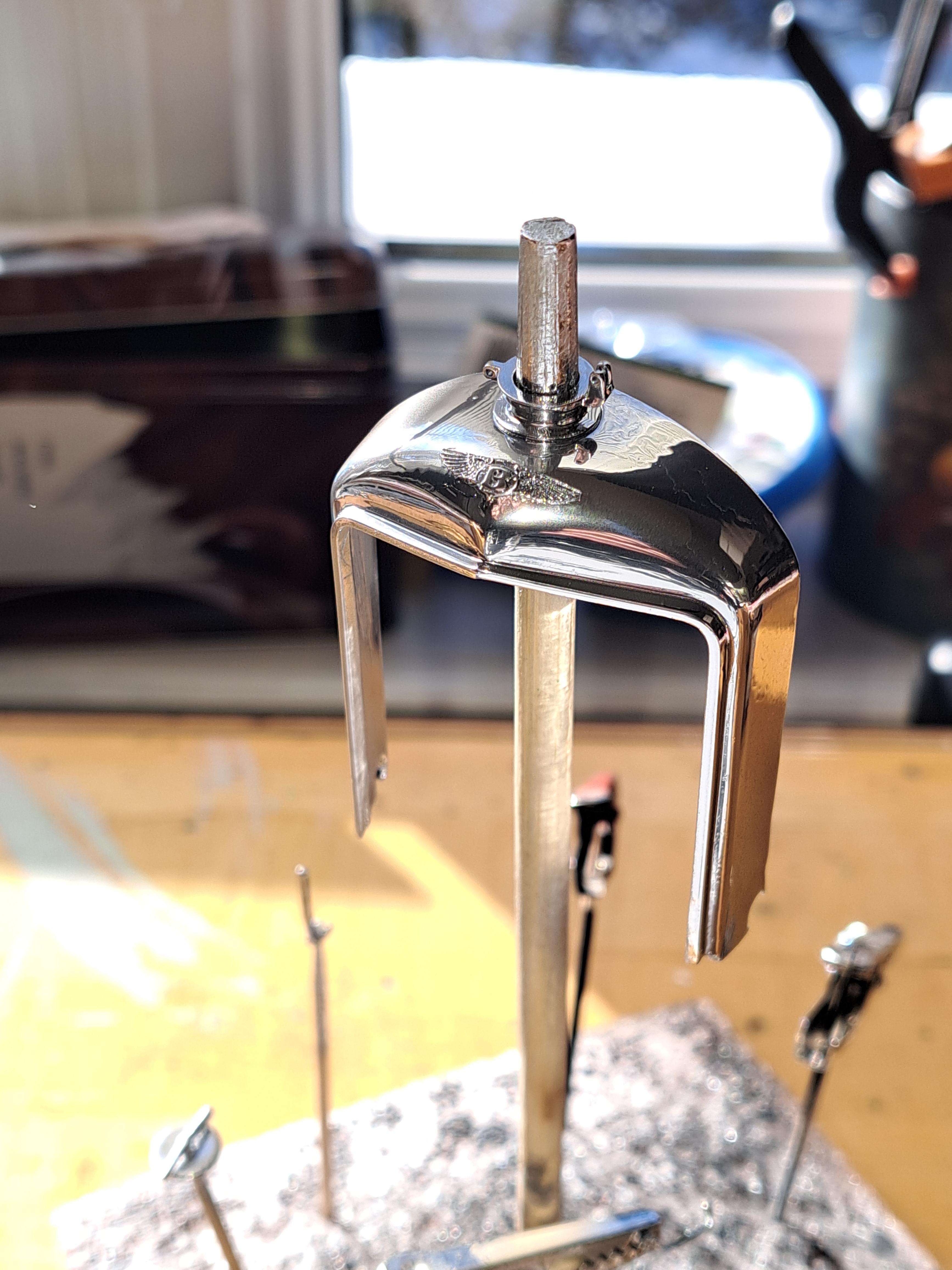
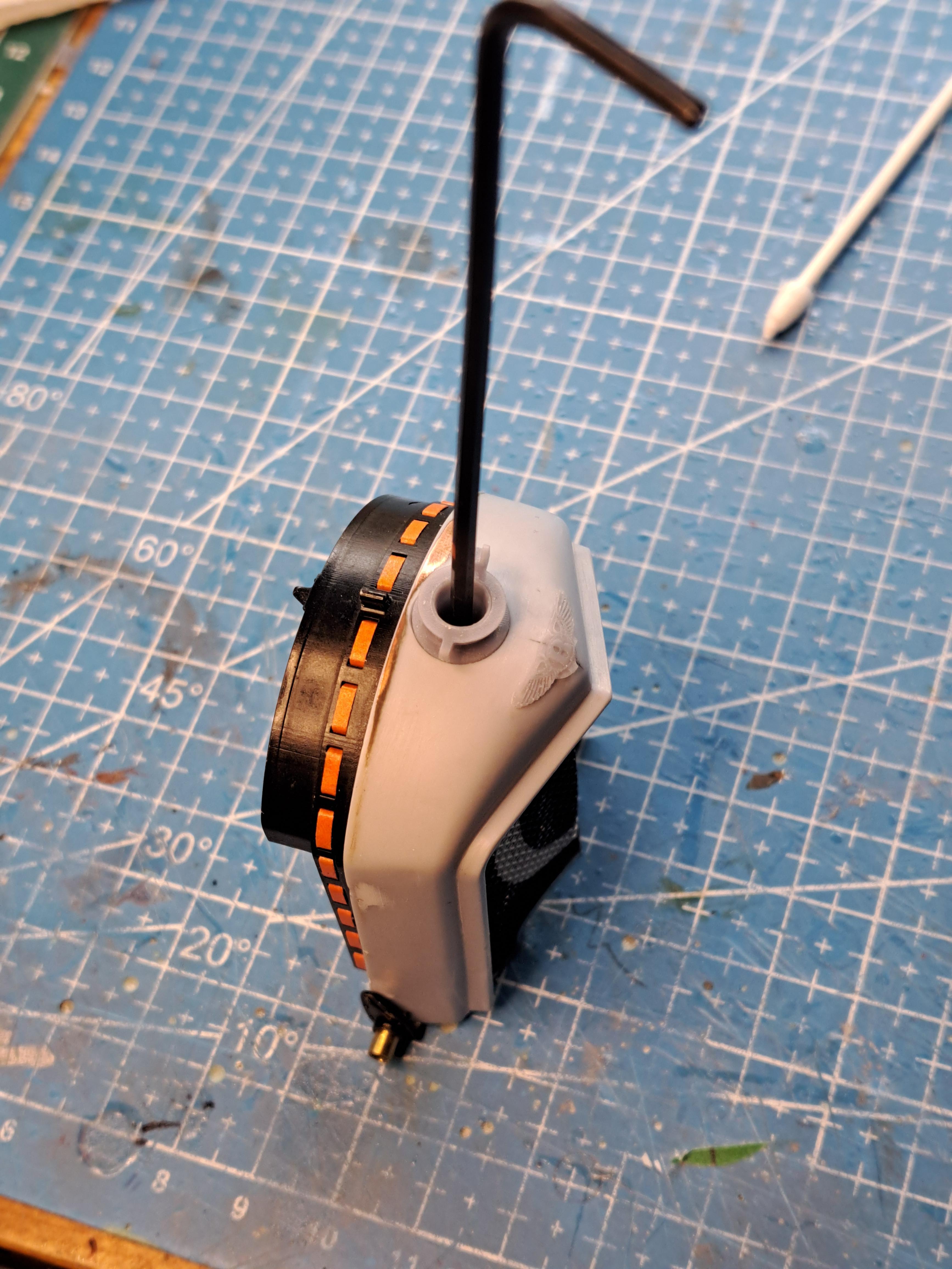
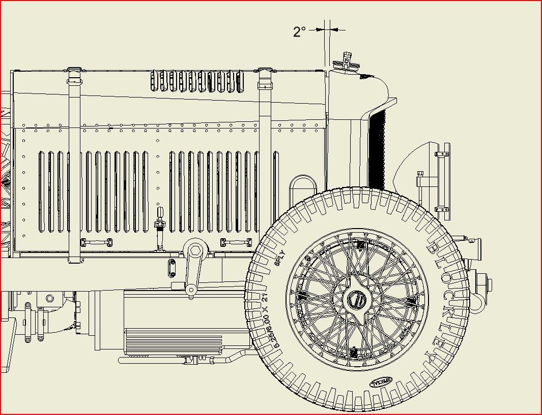
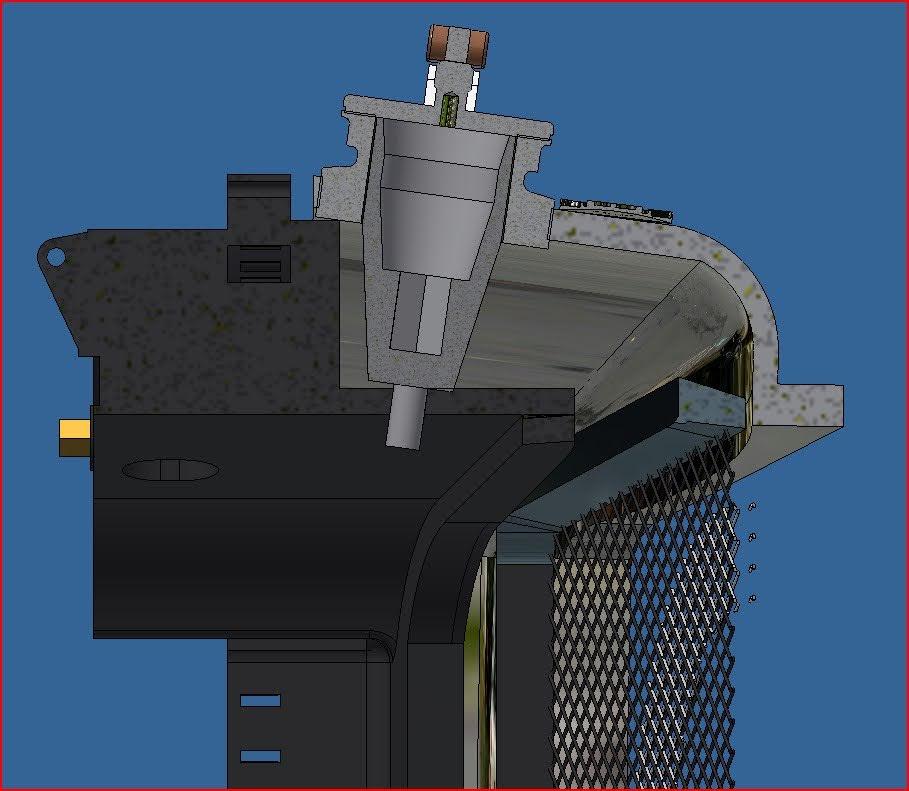
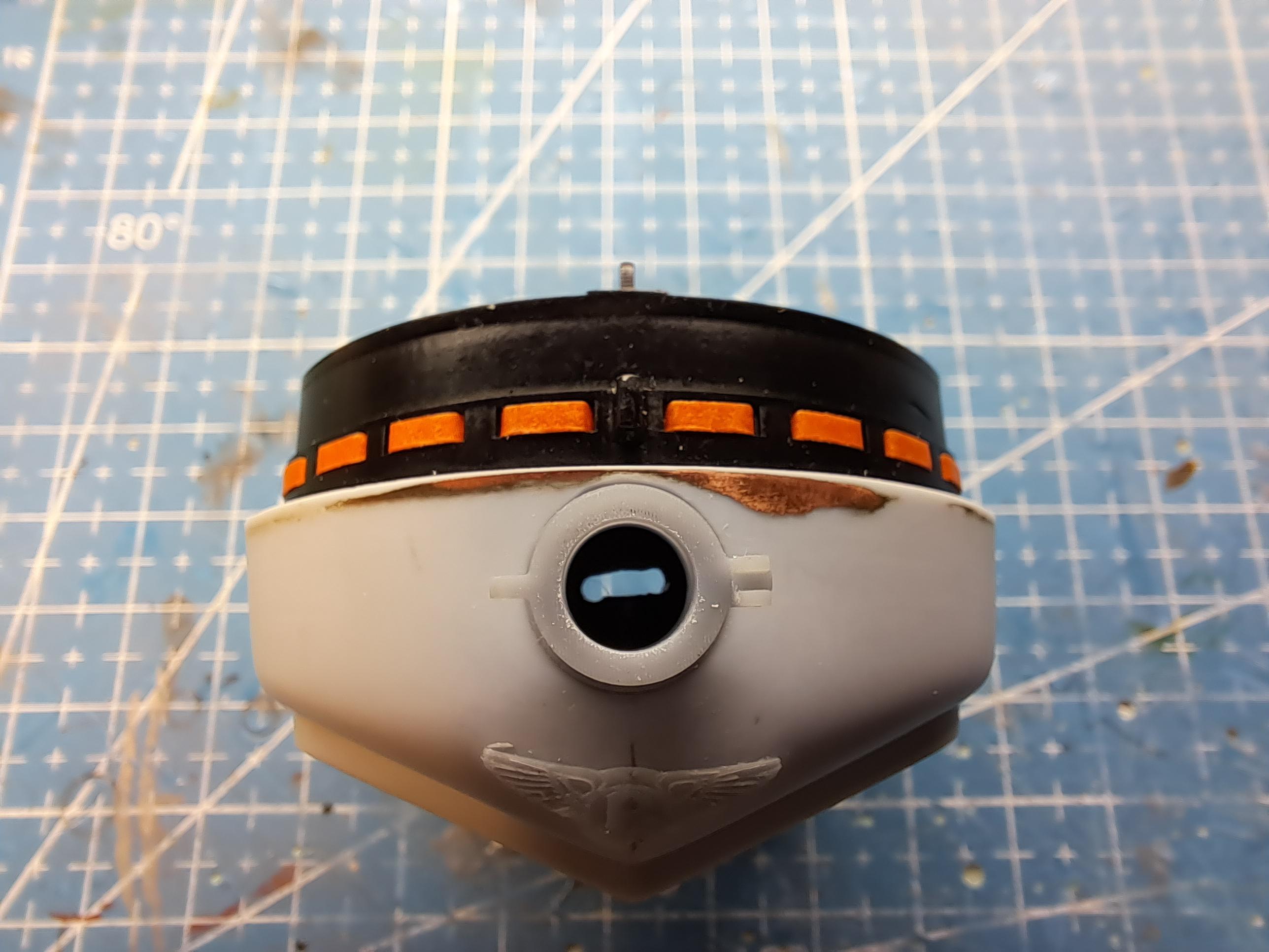
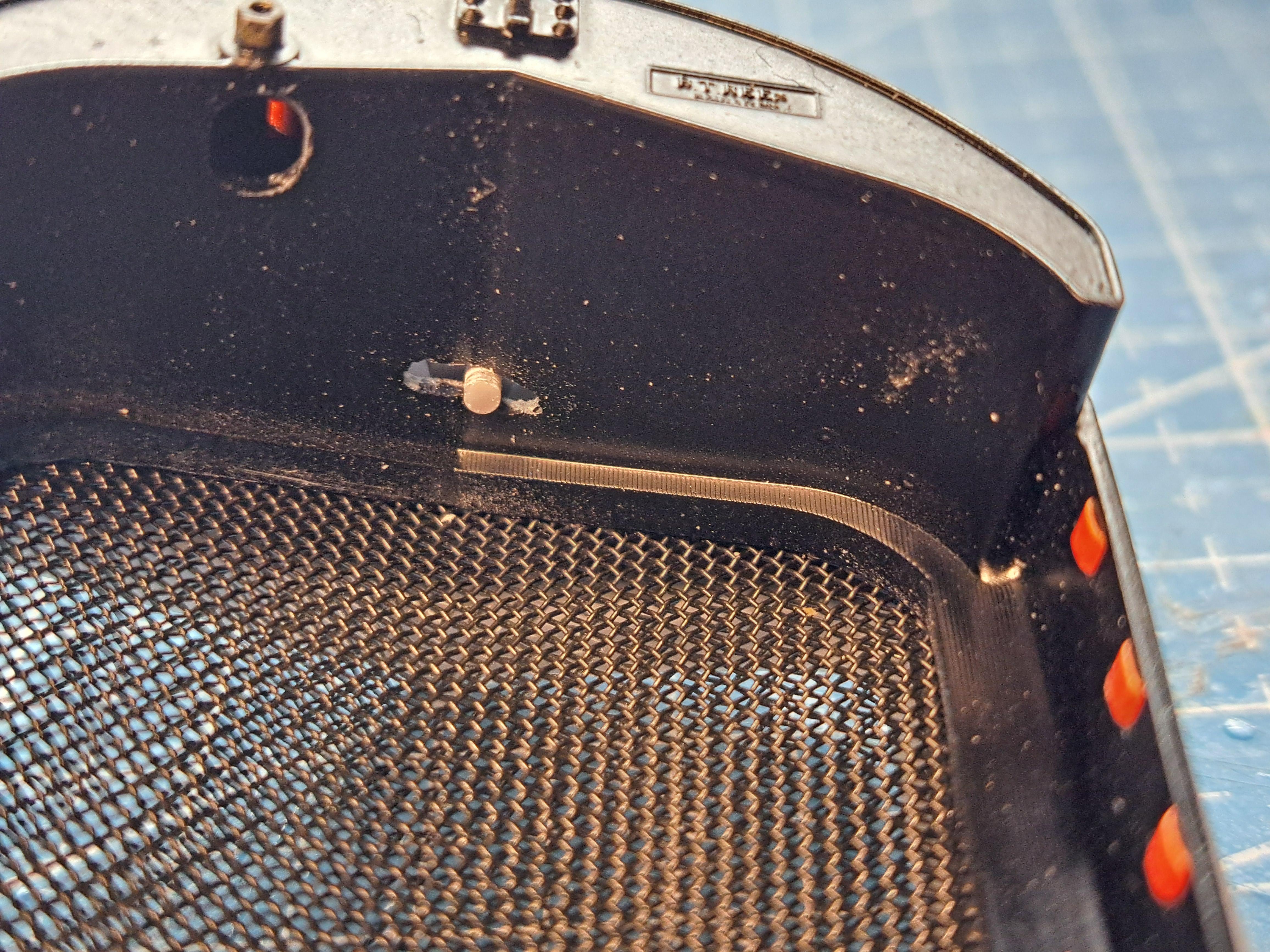
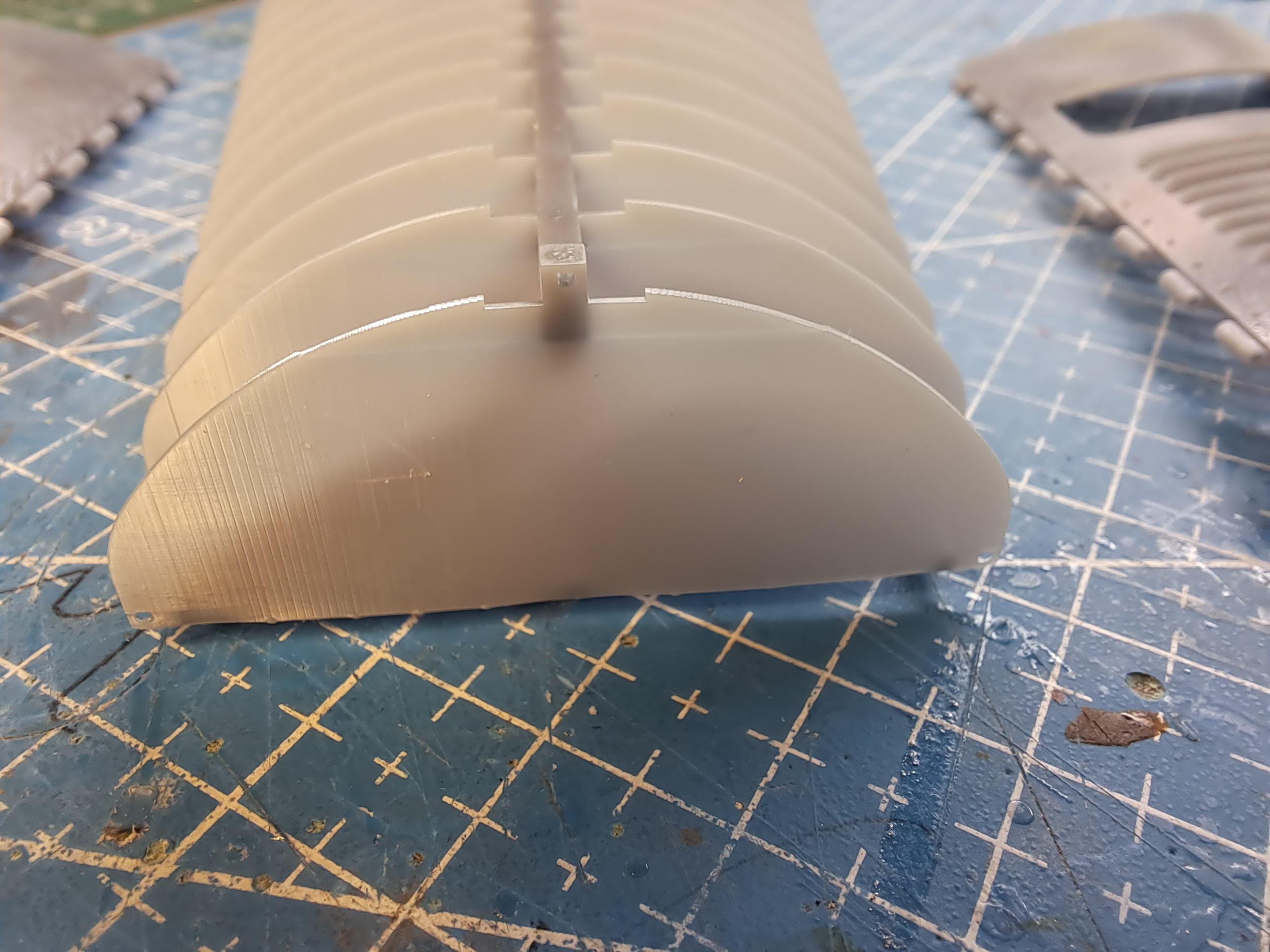
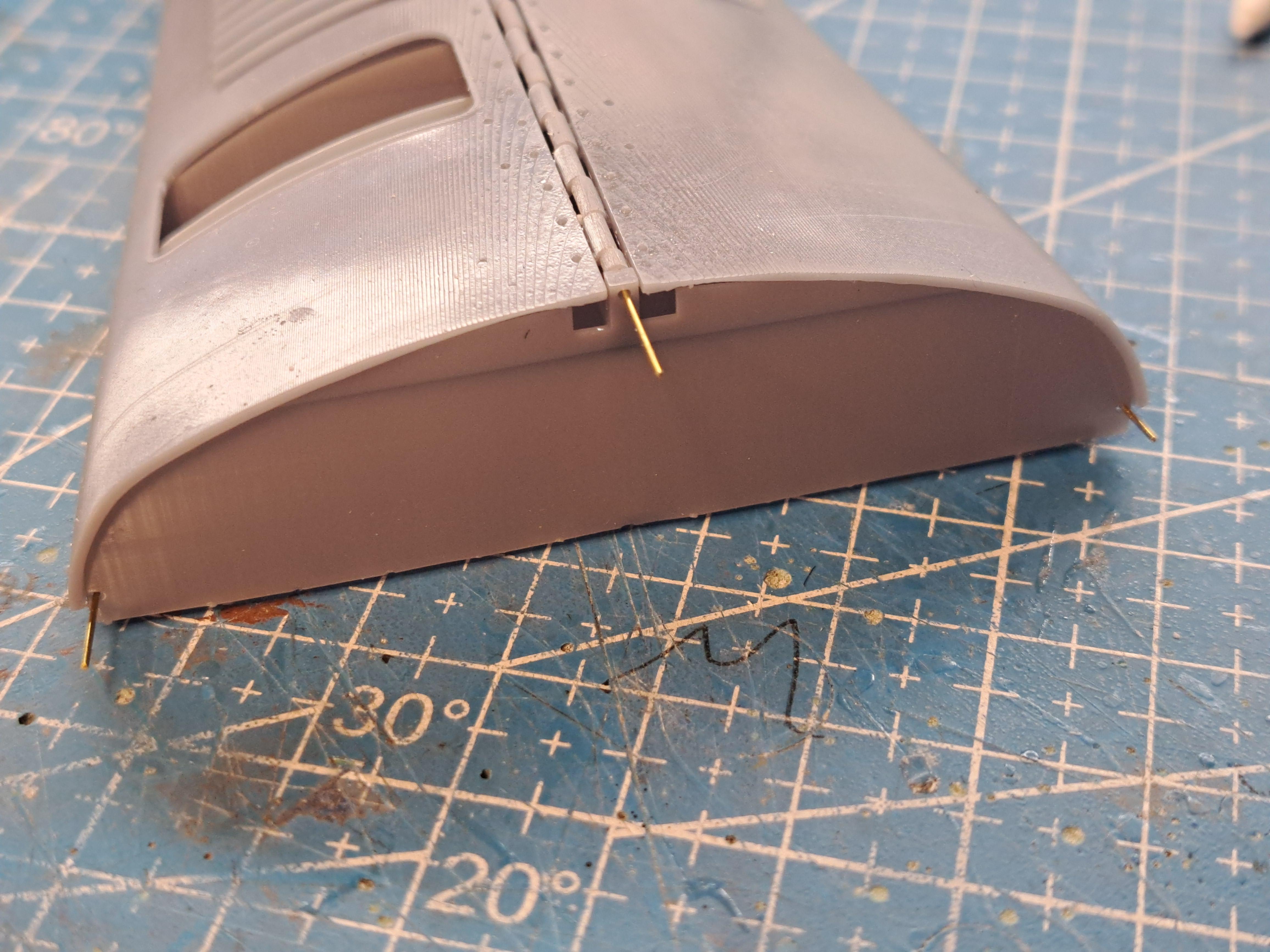
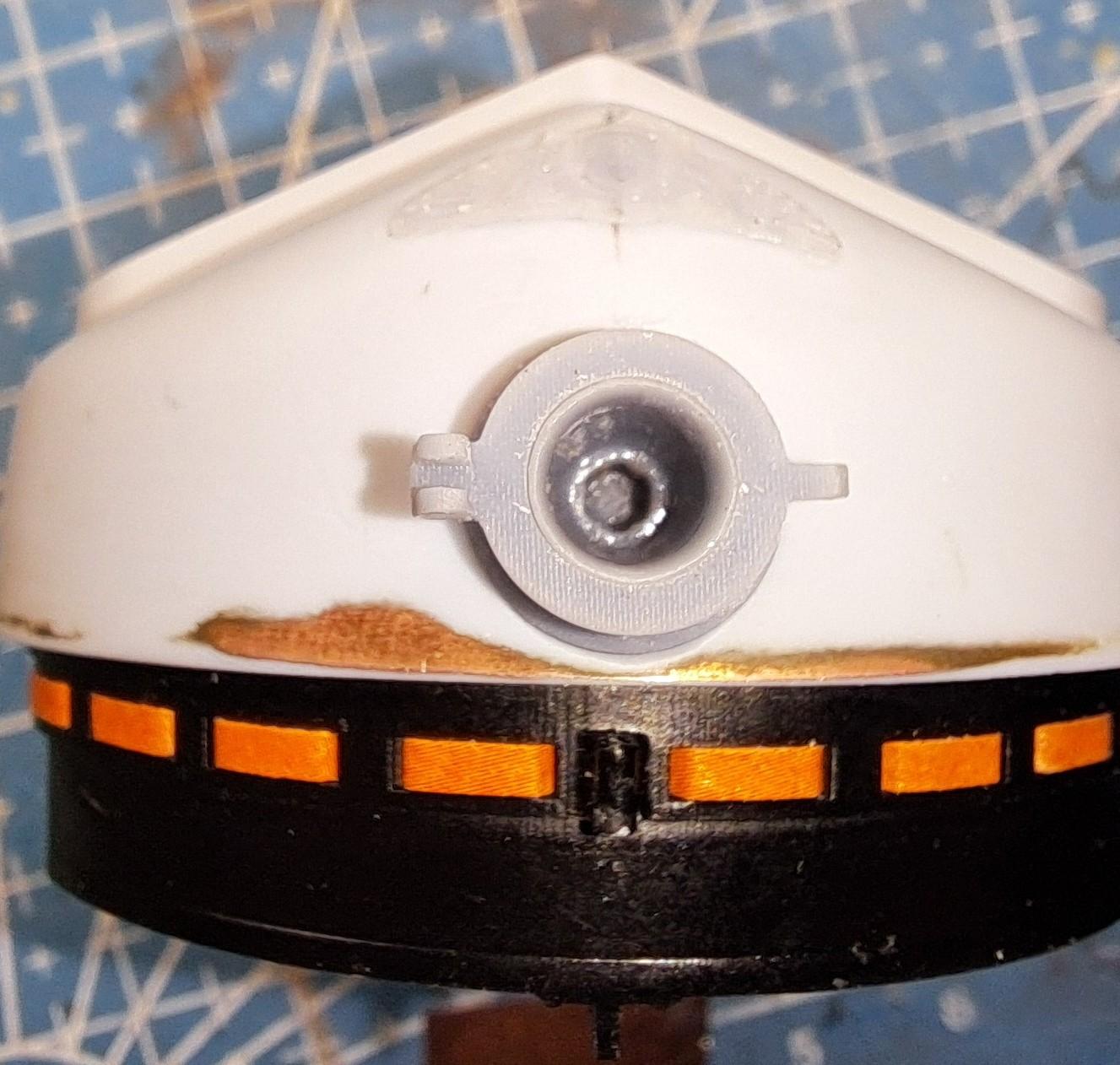
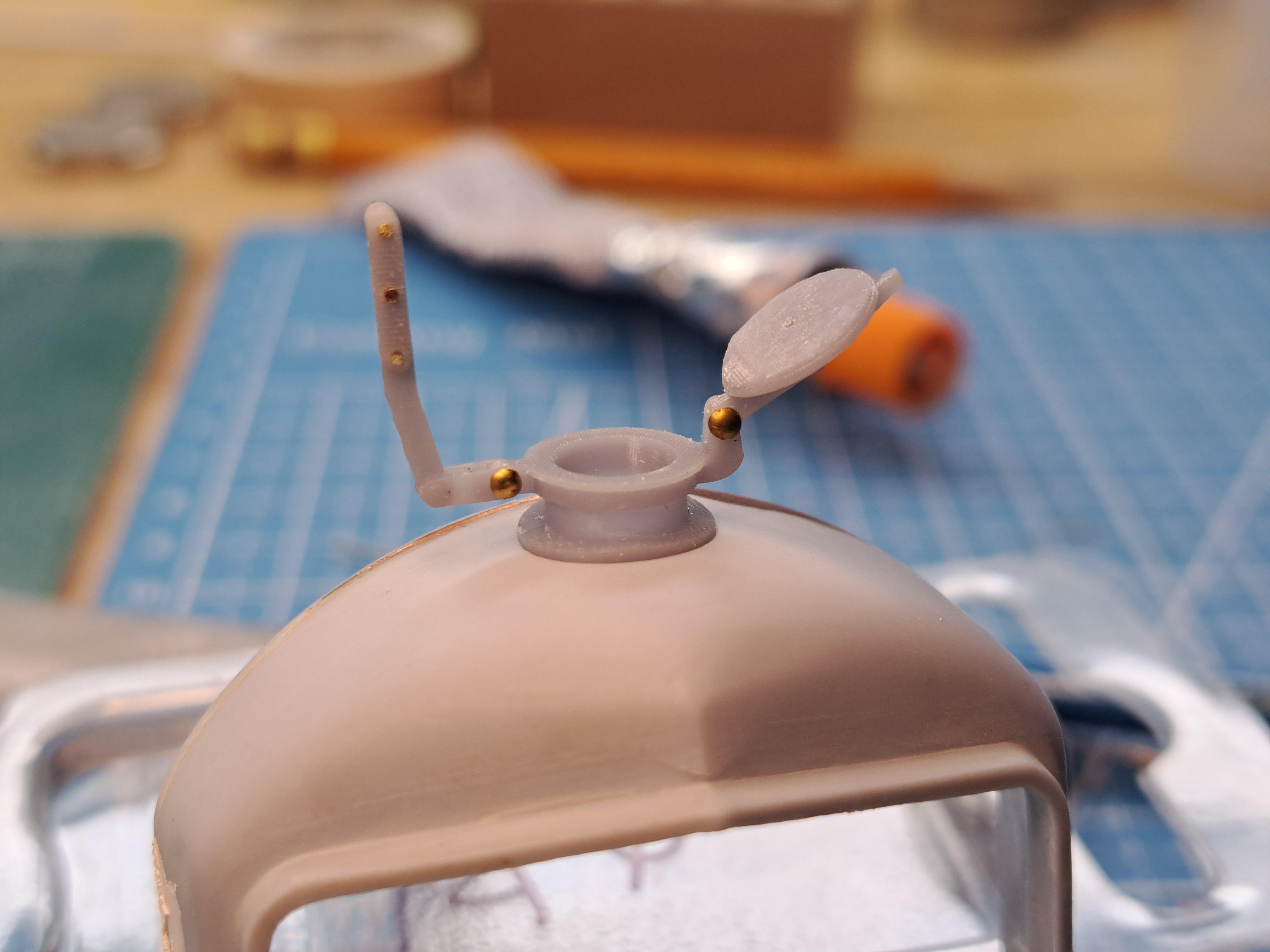
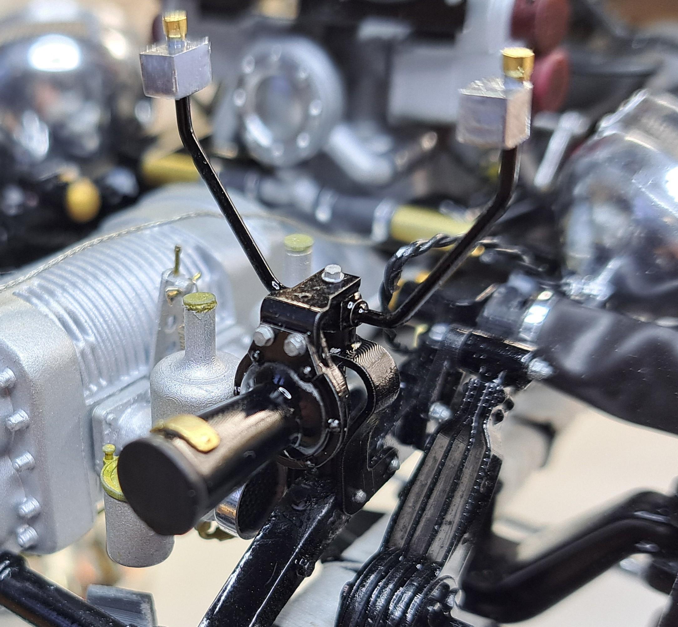
Like I mentionned before, I've made so many modifications/add-ons on this model that I have to take certain measures to assure correct fit and alignment. I tackled 2 of these measures over the weekend. Since I printed new thinner hood panels to replace the bulky looking ones from the kit, one problem I'm face with is to try and maintain the correct curvature of the 2 top panels. When a part come out of the washer after printing, it is still very soft and can be deformed a bit just by manipulating it. So I made a curing fixture to conform the panel during curing. The fixture has the exact shape of the top panel as there are once installed on the model. I incorporated holes that align with the hinges, that way, the panels are firmly held in place at exactly the correct relation. Here are a few pictures. The fixture worked perfectly and held the panels during curing. I'm designing a similar fixture for both side panels as well. The second measure was a bit more tricky to figure out. It's the alignment between the radiator and the hood panel. I want to hava as close to an even gap as possible between them. But, since almost everything in this section of the model is new, the gap is not parallel. In the following pictures, I want the angle show as close to zero as I can get it. to achieve this, I designed a mecanism that will permit me to ajust this angle once the radiator and the hood are permanently in place. I made a sleeve that fits inside the radiator cap. This part will be glued in place once the ajustement's done so it will be painted black to look like the radiator filler tube. At the end of the sleeve, I added a small stud that as a .035in excentricity. This means that when the sleeve rotates, the stud move on a .07in diameter circle (2x the excentric). I also added a hex socket on the inside the drive the sleeve with a small allen key. To work, the excentric stud is engaged in a slot I made in the radiator core, the slot has the same width as the diameter of the stud. By rotating the sleeve, the stud move the radiator cover in relation to the core and since the cover is mounted to the core via a pivot point at the bottom, the angle between the 2 parts varies. Here's the design The sleeve, you can clearly see the excentric stud. The slot seen thru the filler cap The hex socket And the key Here you can see the stud in the slot And finally, a little video showing how it works 20240204_204438~2.mp4 I hope my explanations are clear.
-
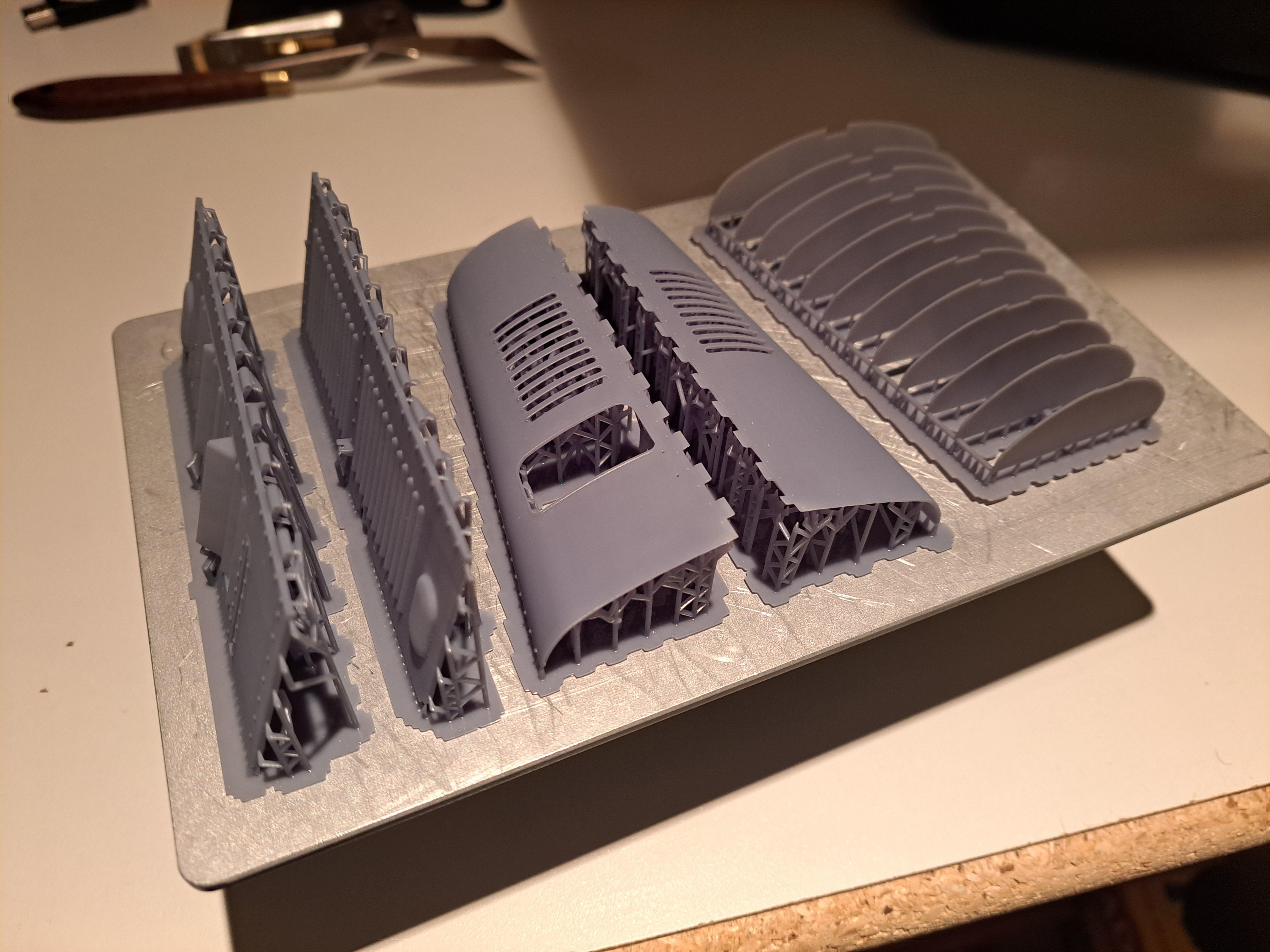
I worked a bit on a more accurate tire model. I might try to print it with a flexible resin to see if it could better fit the wheel. I also reprinted the hood panels with a curing fixture ( on right side of print plate). The idea with this fixture is to try and conforme the curved panel while curing.
-
Absmiami, is that a good sigh or a bad sigh?
-
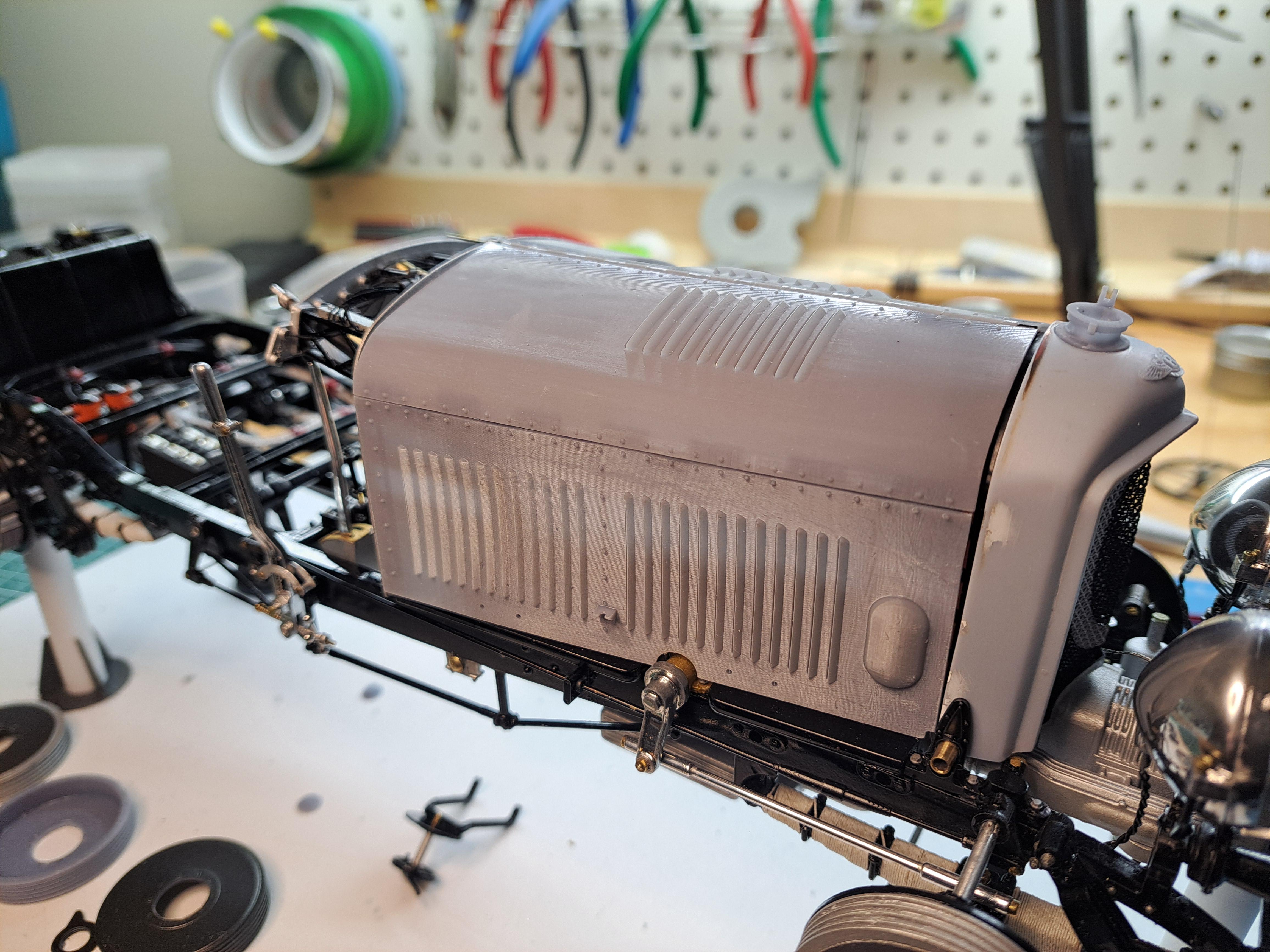
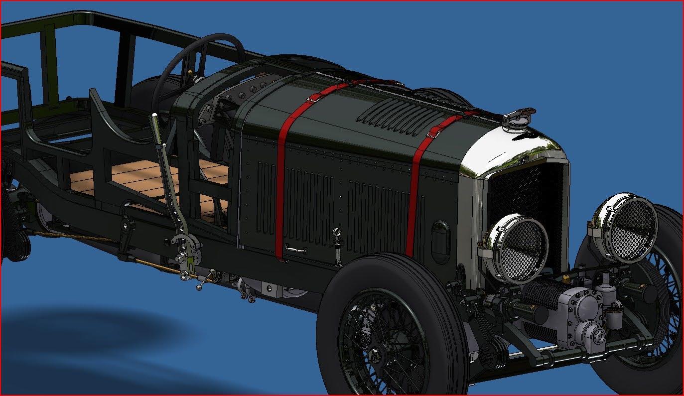
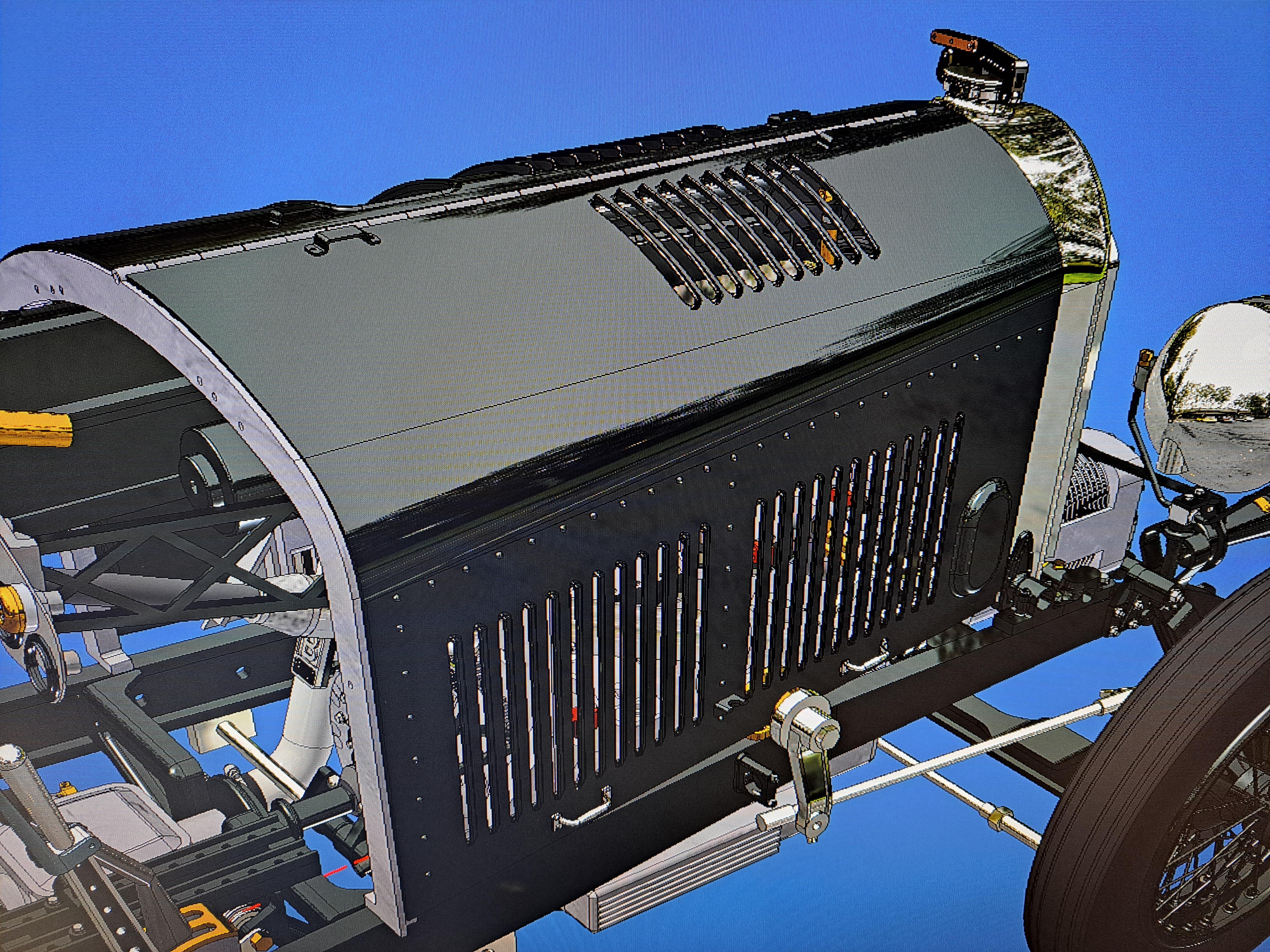
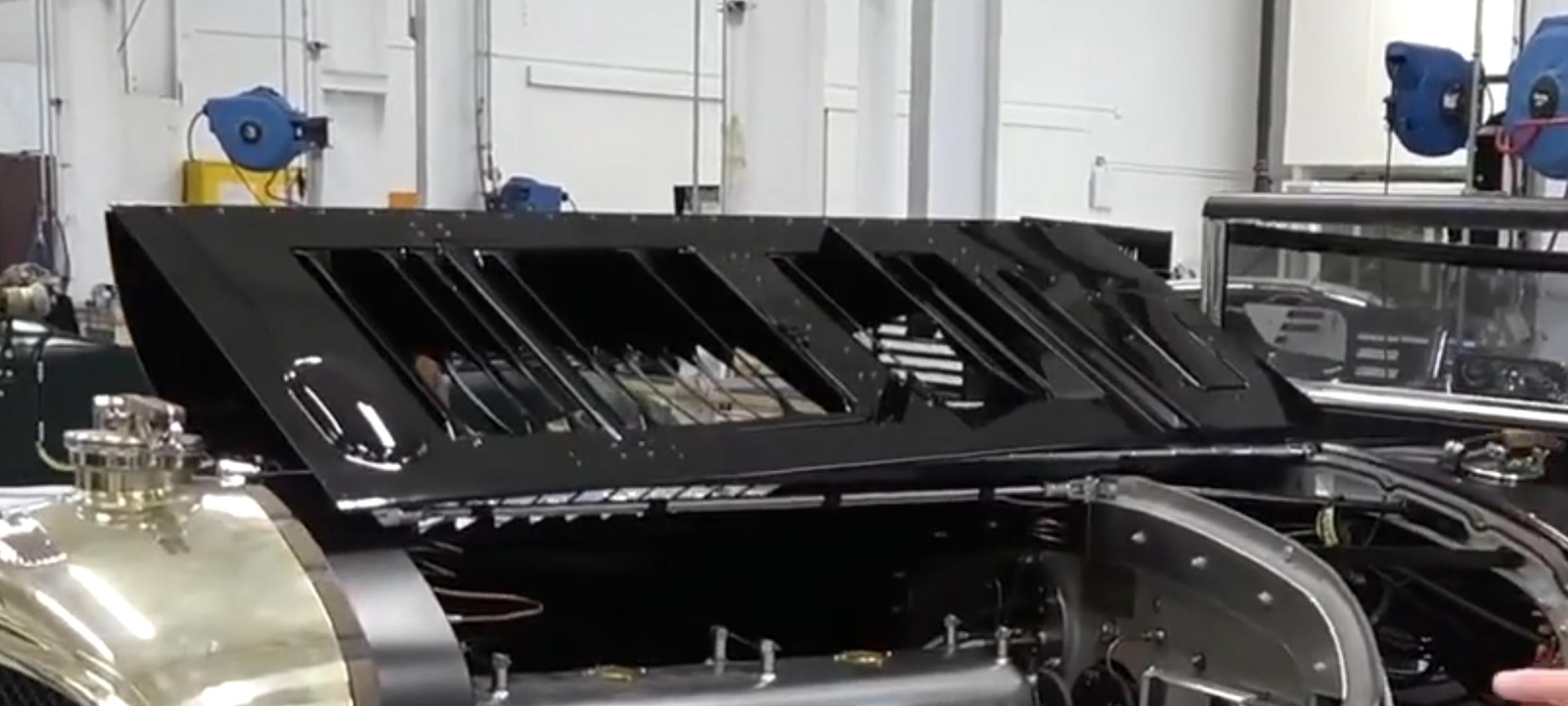
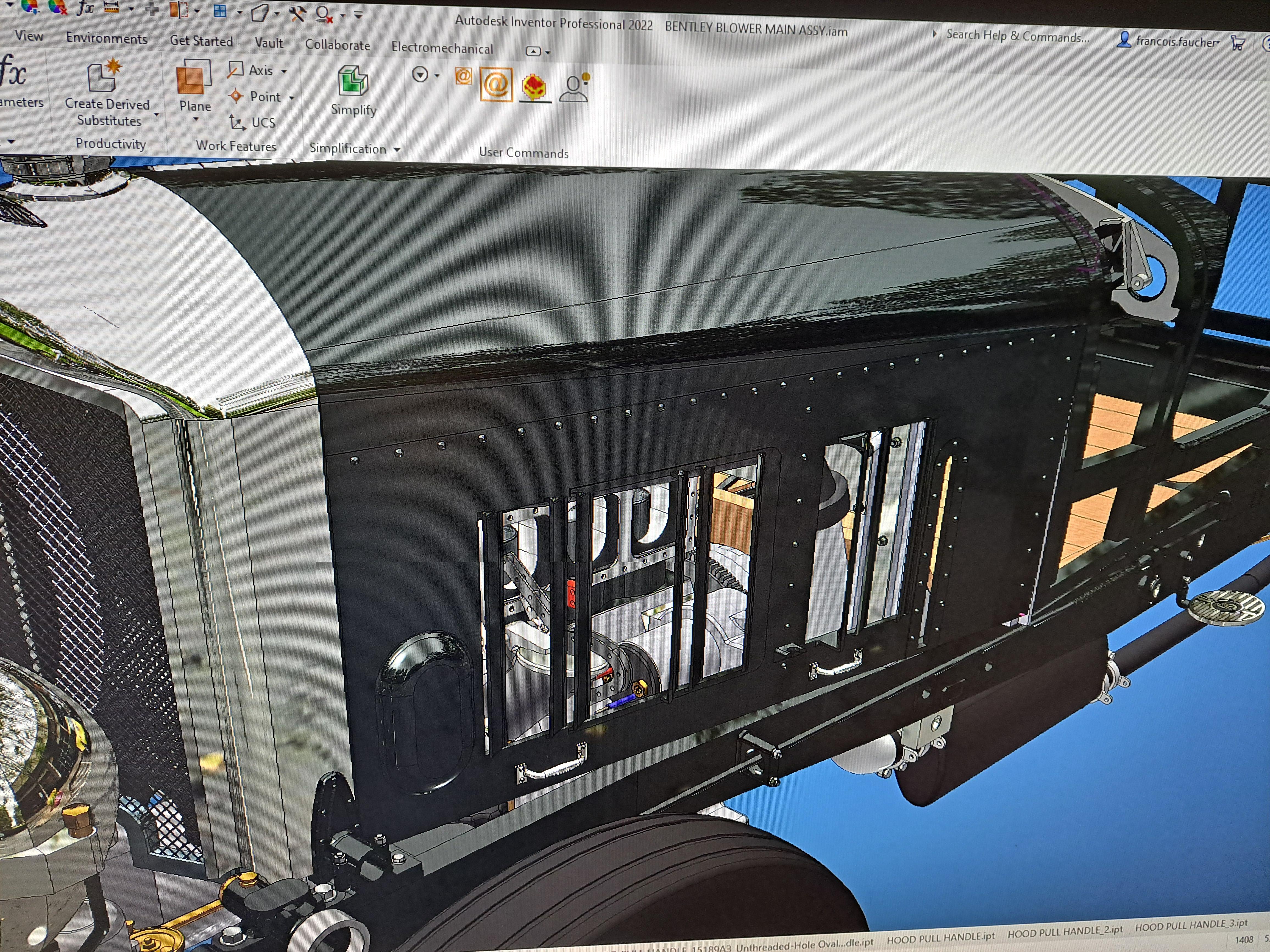
Ok so it's hood update time. So far, the 4 panels have been 3d modeled with better details than the kit's and incorporated hinges. I modeled the lifting handles and the latch. I even modeled the straps (I'll fabricate real straps, not printed ones). The 3d model look pretty good. But this is not a cad model forum, it's a scale model forum. So here's where I'm at with my real model. I printed (again) the hood panels, this time with a thickness of .03in, up .005 from the last print. I'm very happy with the result but I think I could do better. I might up the thickness another 005. to give them a little more rigidity. I also need to tweak certain de curves a little but aside from that, l pretty much there. So here are some pictures. Please remember that the radiator is not uet fixed in place, that's why it's a little off. Printed panels before supports removal Right side panel down Right side panel up Left side panel down Left side panel up Latch And finally, real car vs cad model vs scale model
-
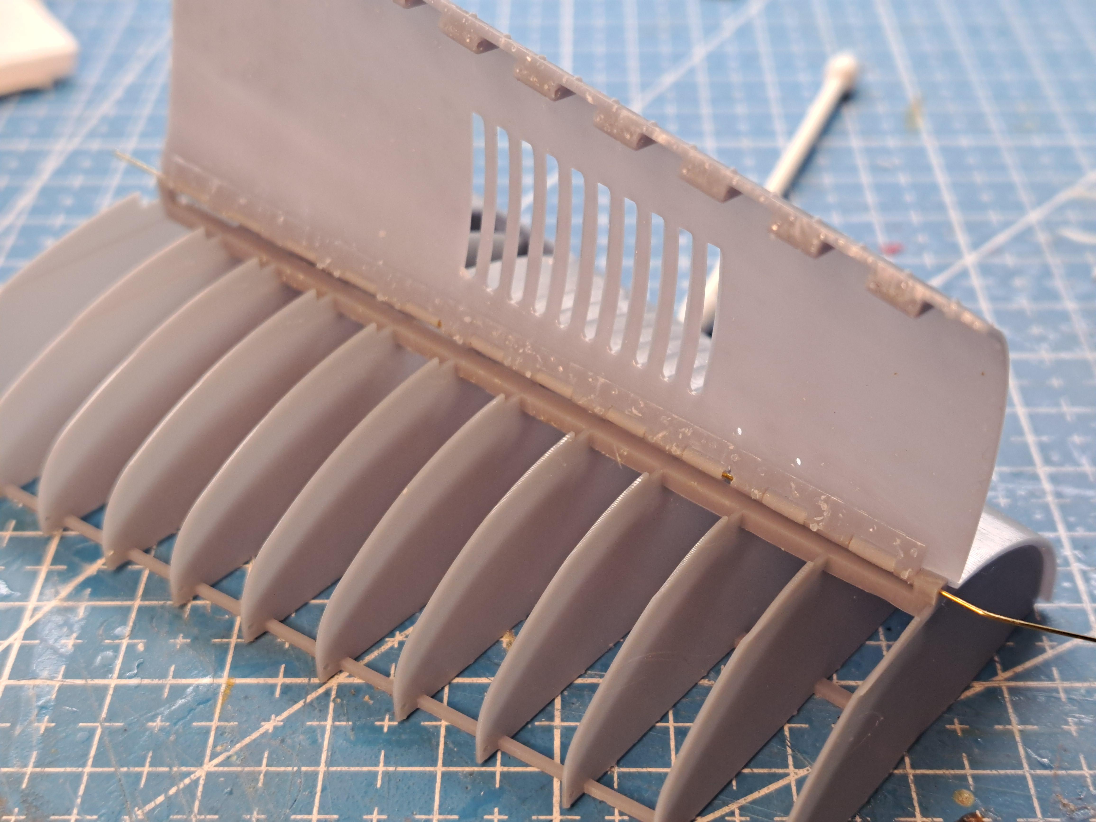
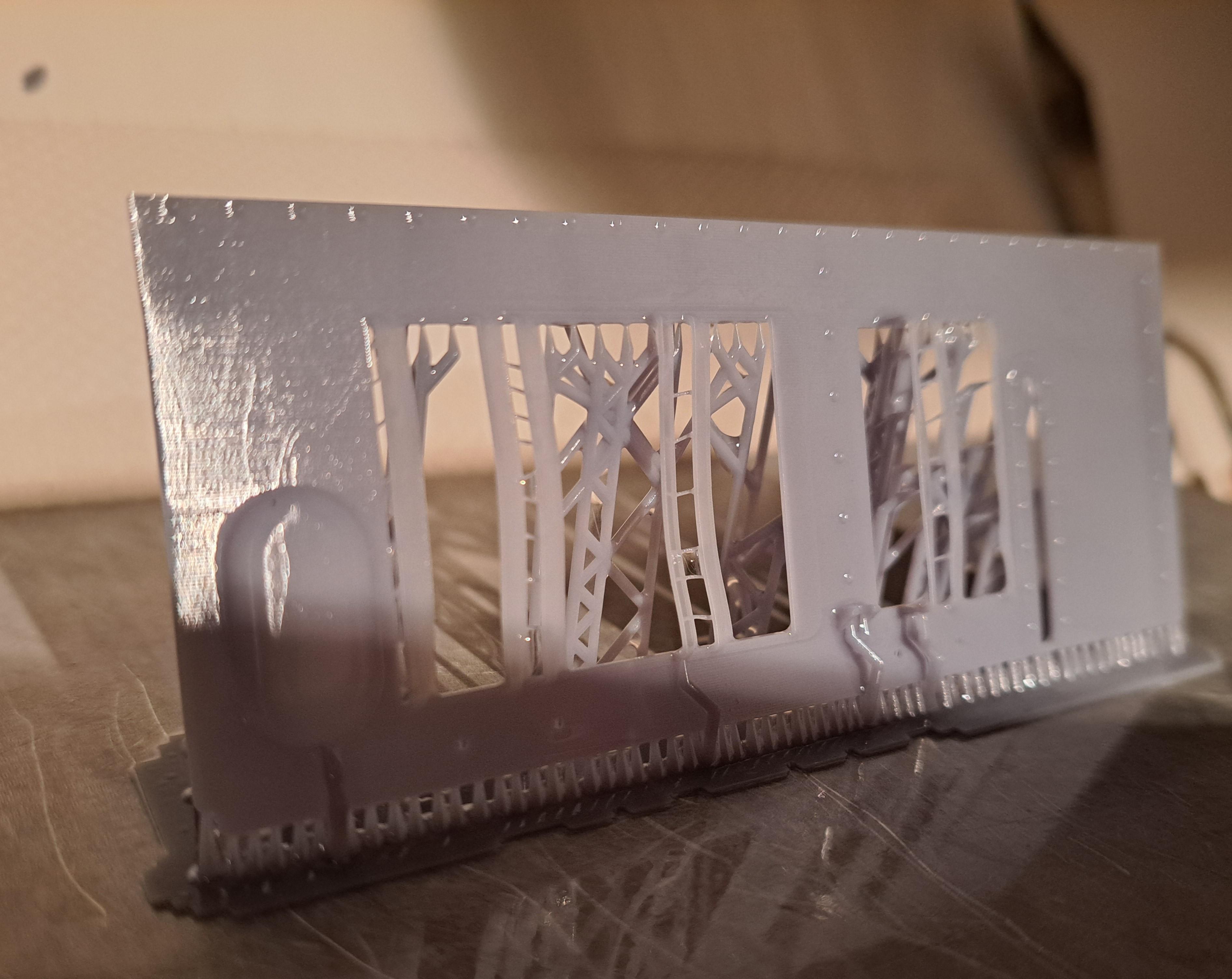
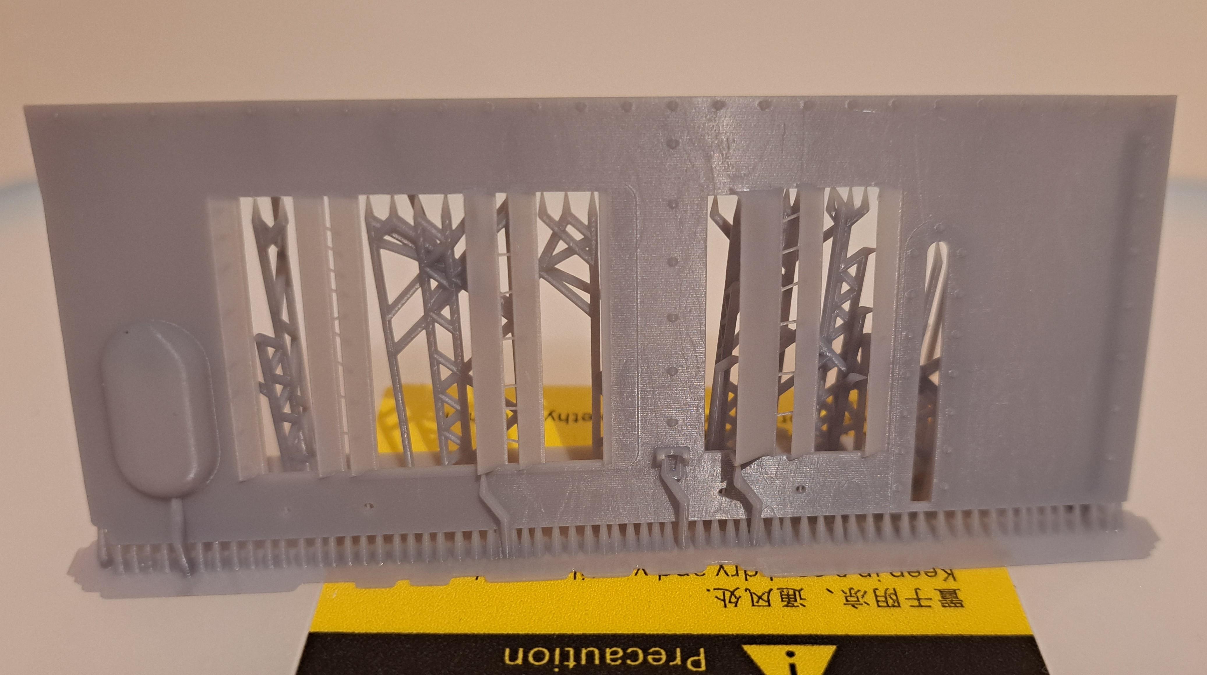
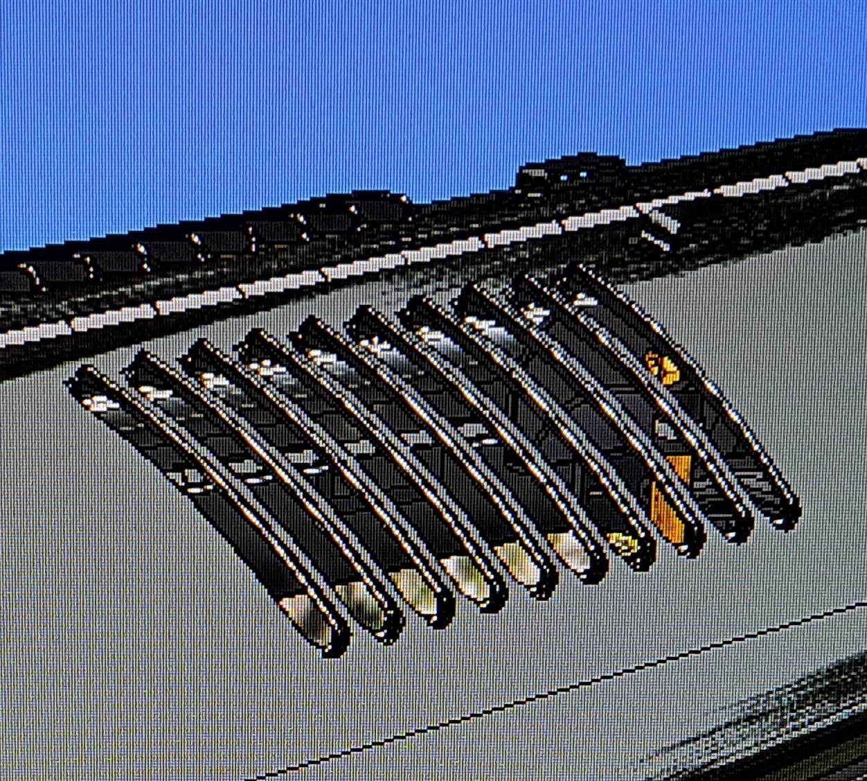
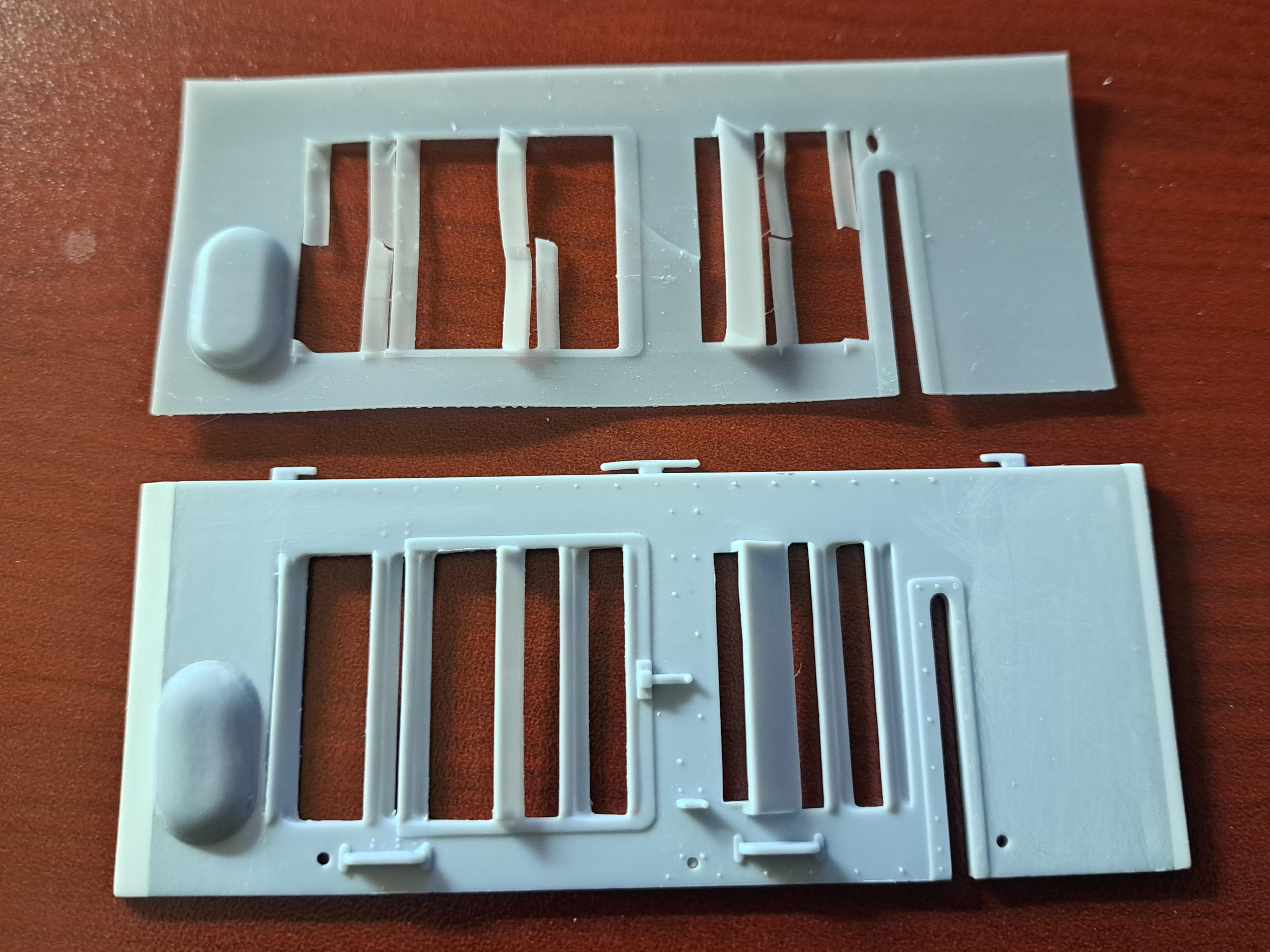
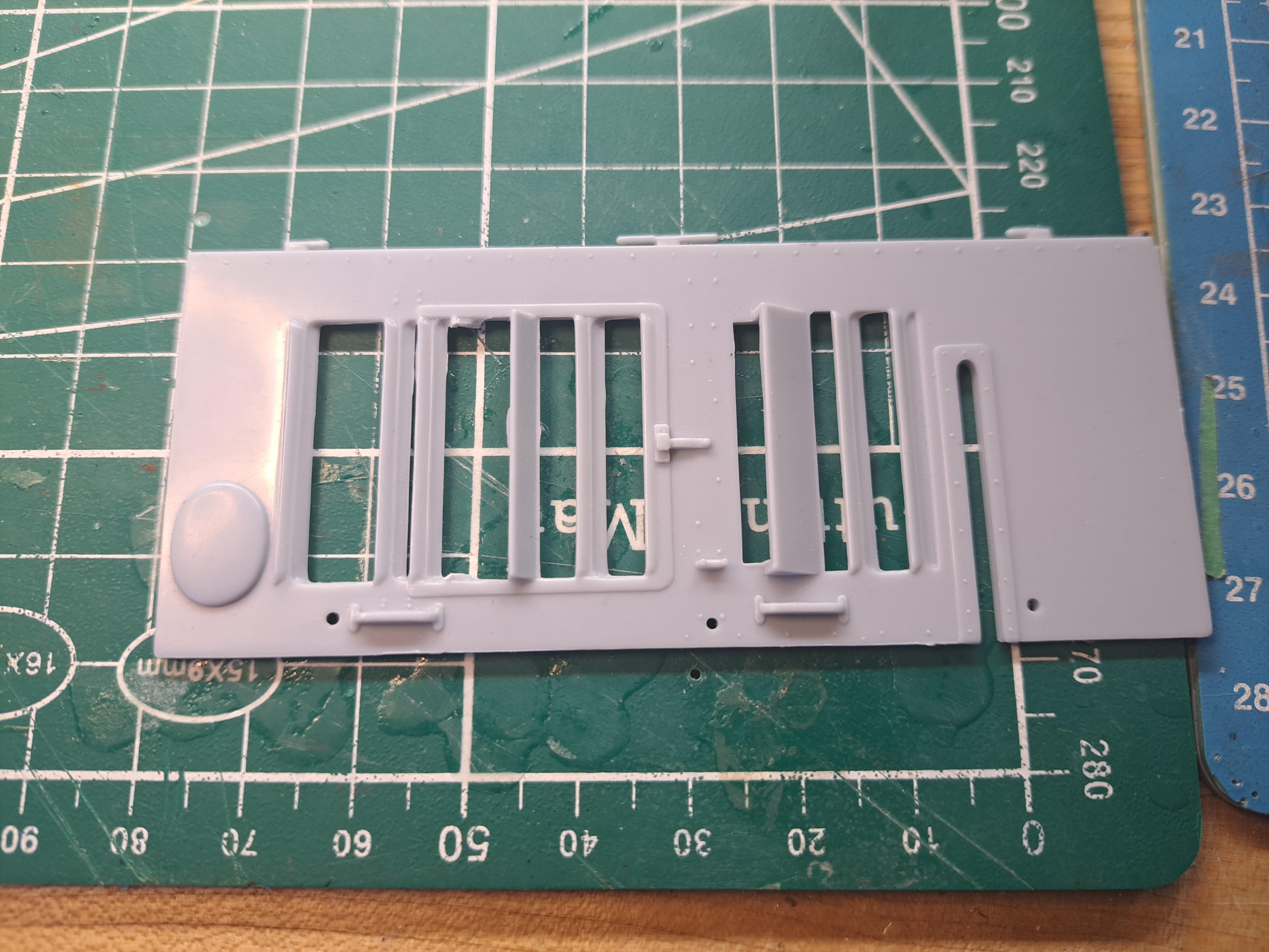
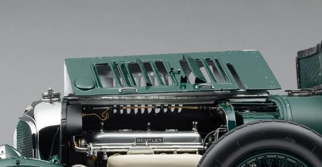
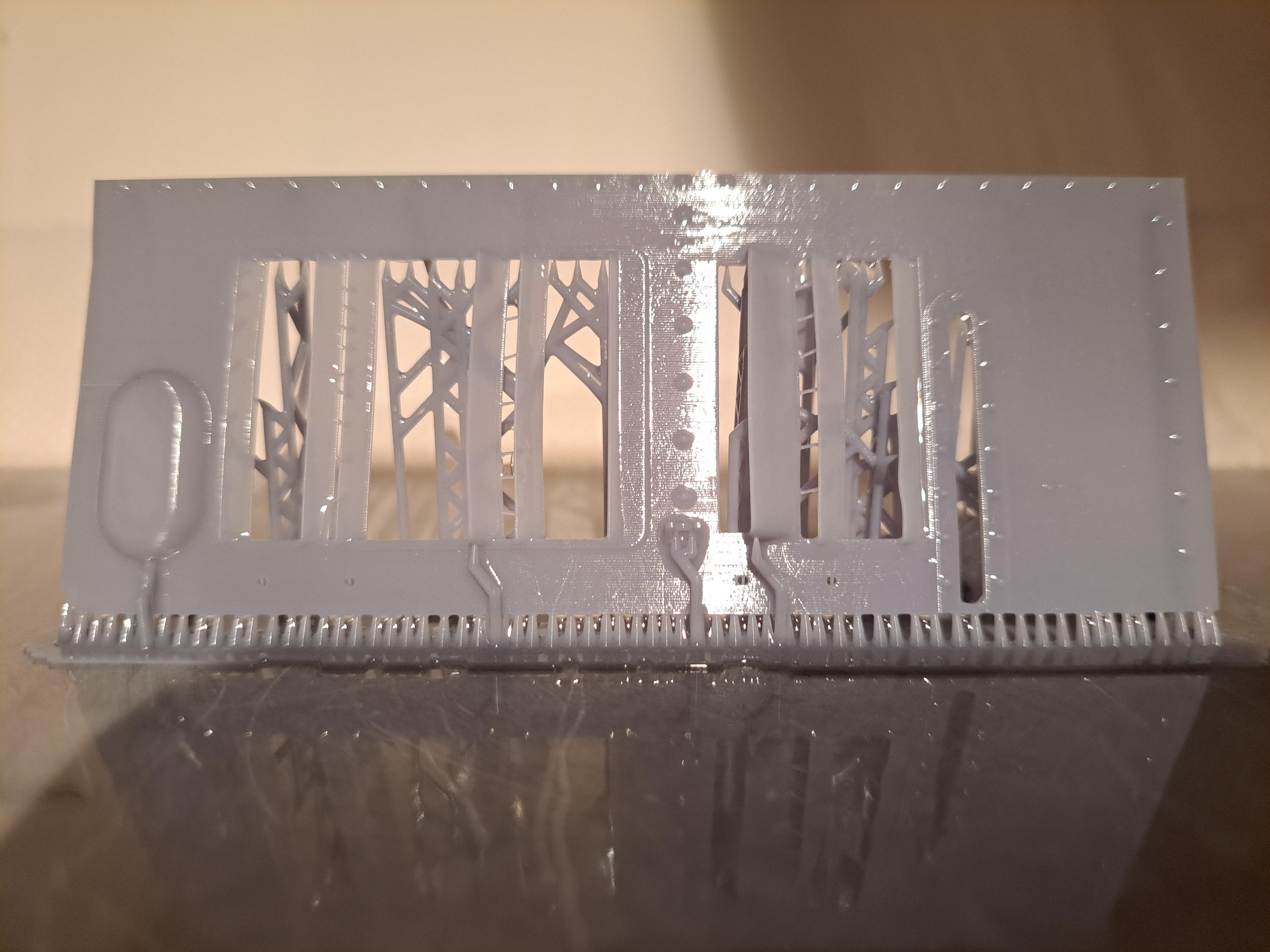
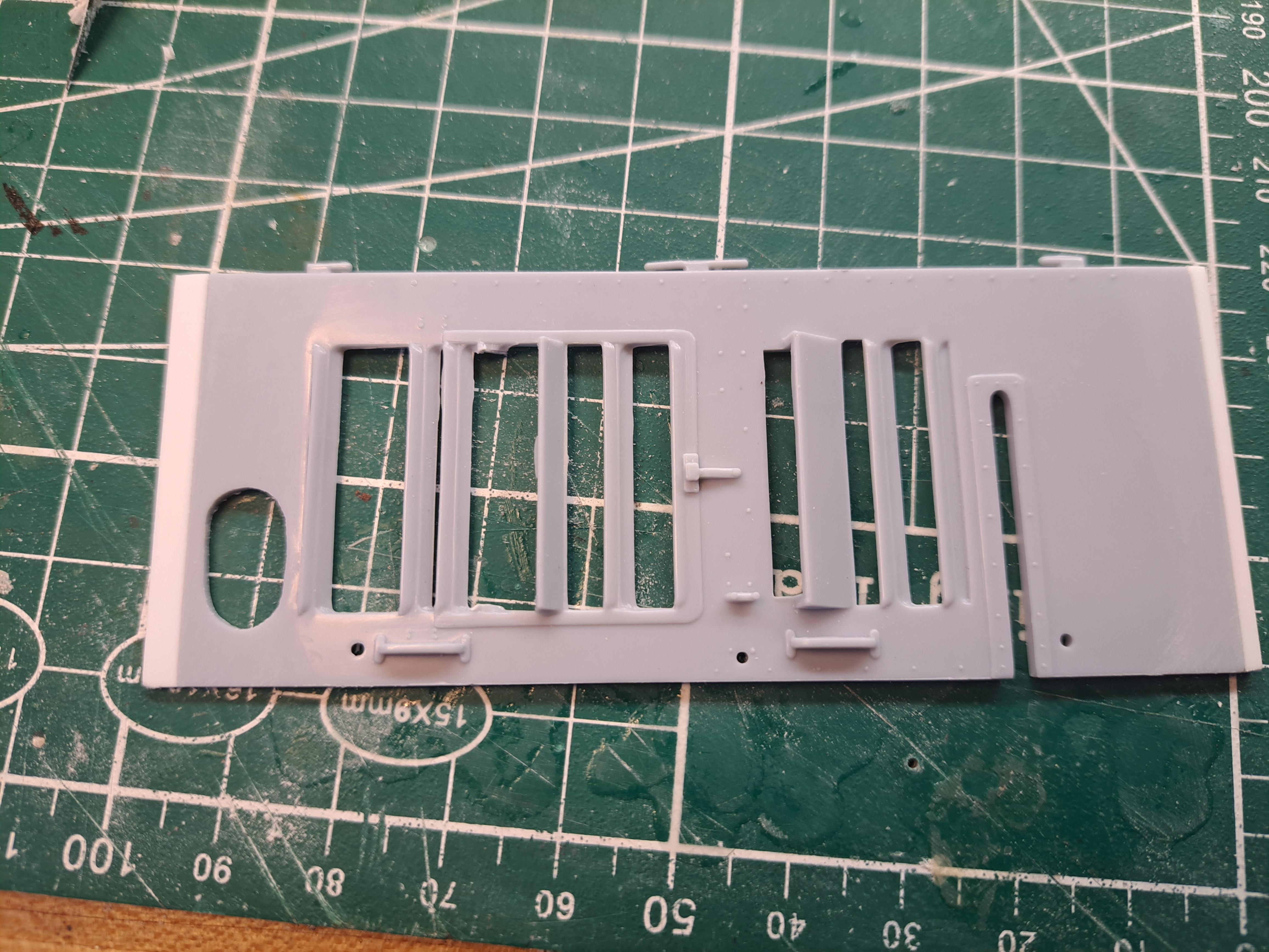
Well, like I've said before, live and learn. And today was definatly a 'live and learn ' day. On my previous post, I mentionned that I tried printing a side panel. First try was no good. As for the second try, the panel itself was ok but the louvers still too flimsy. At least, that's what I thought. So here's the live and learn moment. It appears that long thin part, like the louvers, will straighten up as they dry after the wash, before the curing. On my first panel try, I cured the part right after washing. But on my second try, it dried overnight and to my surprise, all louvers were straight as arrows this morning. This is the second print right after washing last night And this is what it looked like this morning you can clearly see the flatness of the louvers. So now enriched with this lesson, I spent the entire day 3d modeling the 3 renaining panels, getting them ready for print. The hinges are all modeled directly on the panel so no more printing a bunch of tiny hinge to be glue afterward. I have to say that the louvers on the top panels were a real challenge but I think I got them pretty good. Here are some pictures of the model And again some cad vs reality
-
I continued fitting the hood panels today but I find the at .05in, the thickness is way out of scale. I understand that they could not be molded to the correct thickness which would be around .005in for a 1/16 panel, it's just not possible. It was suggested I try making them out of metal sheet. A .01in aluminium sheet would be feasable but making the louvers would be quite a challenge. I could print a forming die of some sort but in order to design the die, I first have to 3d model the panels. So that's what I did starting with the left side vertical panel which is the most complicated because of the different louver sizes. Here's the first panel modeled. I used both the kit's panel, a picture of a real panel and a picture from a 1/5 scale Amalgam model as reference. Since the panel is now in 3d, why not try to print it and see. My firts try was not a success, I put the panel thickness at .02in and the louvers at .01in, not a good idea. The panel is warped and most louvers didn't make it. Top is the printed panel, bottom the kit's I reprinted with a panel thickness of .03 and louver thickness of .02in. I also added a stiffener at the bulkhead end. I couldn't find any info on such stiffeners but I can see rivet lines that could very well be for just that. It's better but still not quite right. The .03 panel thickness should do the trick but the louvers are still to flimsy. I'll try again tomorrow. Fresh off the printer
-
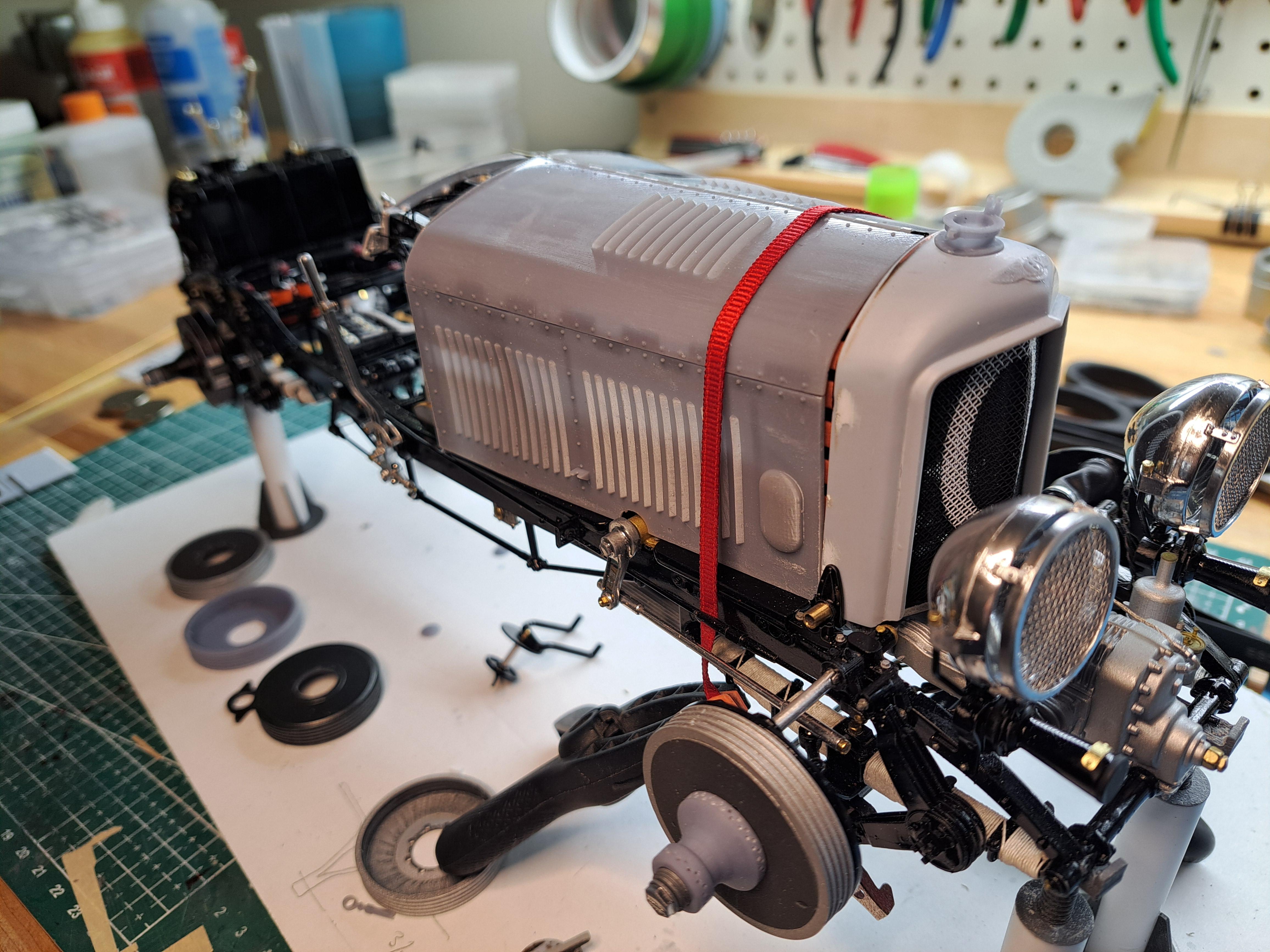
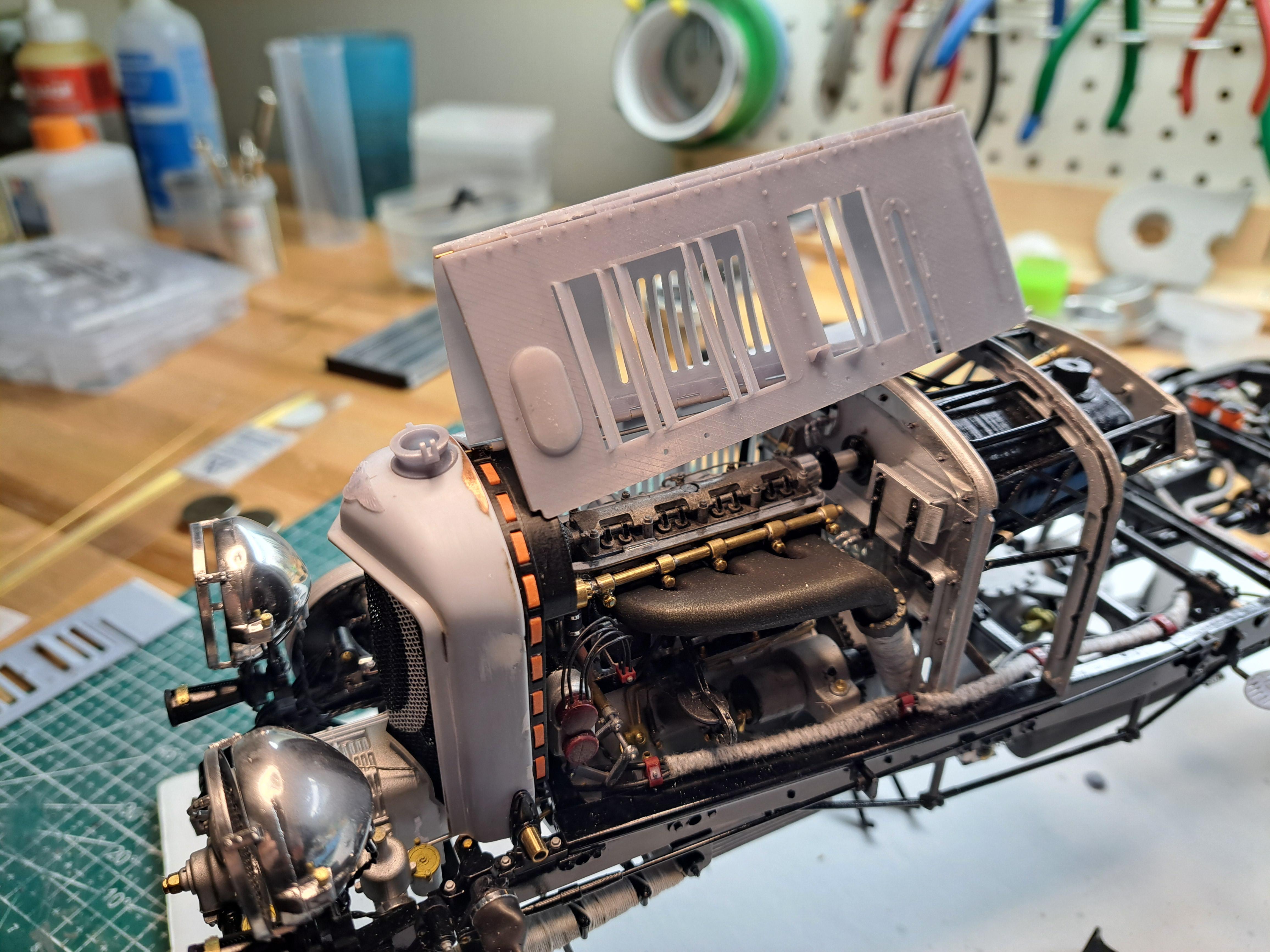
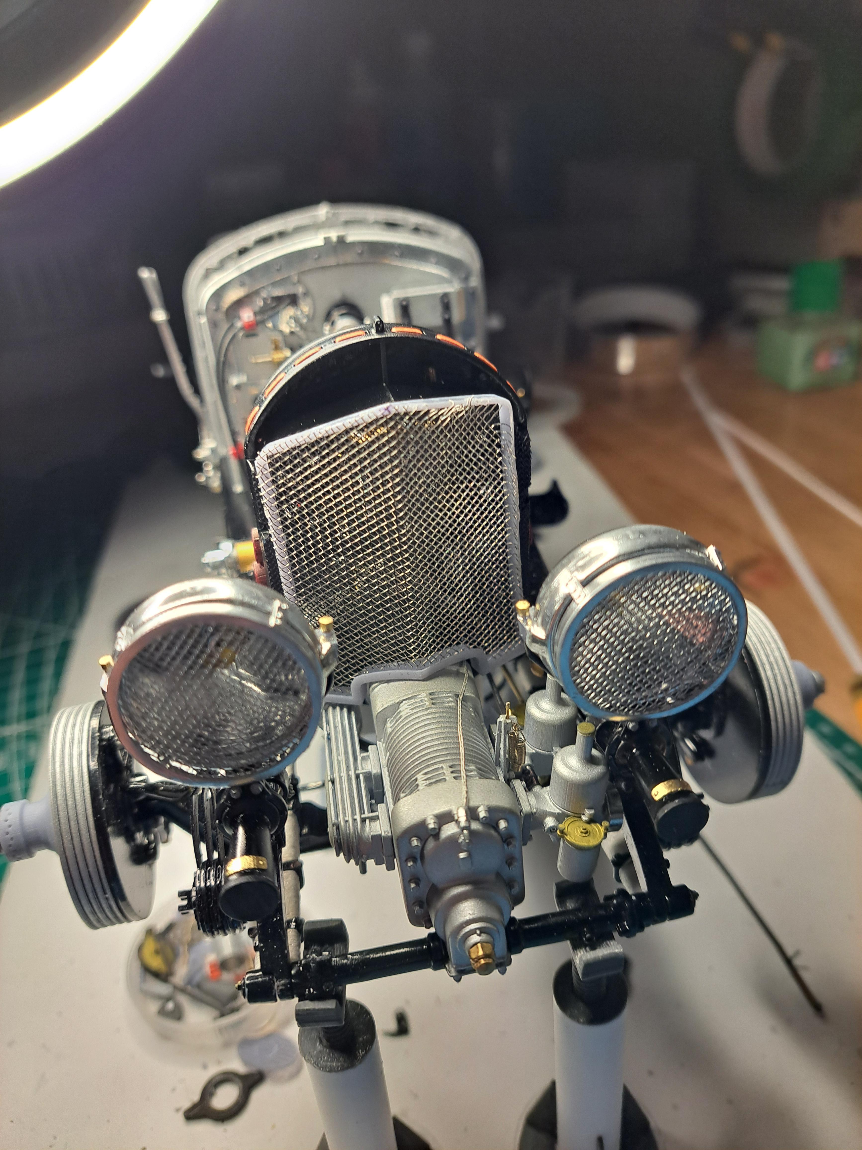
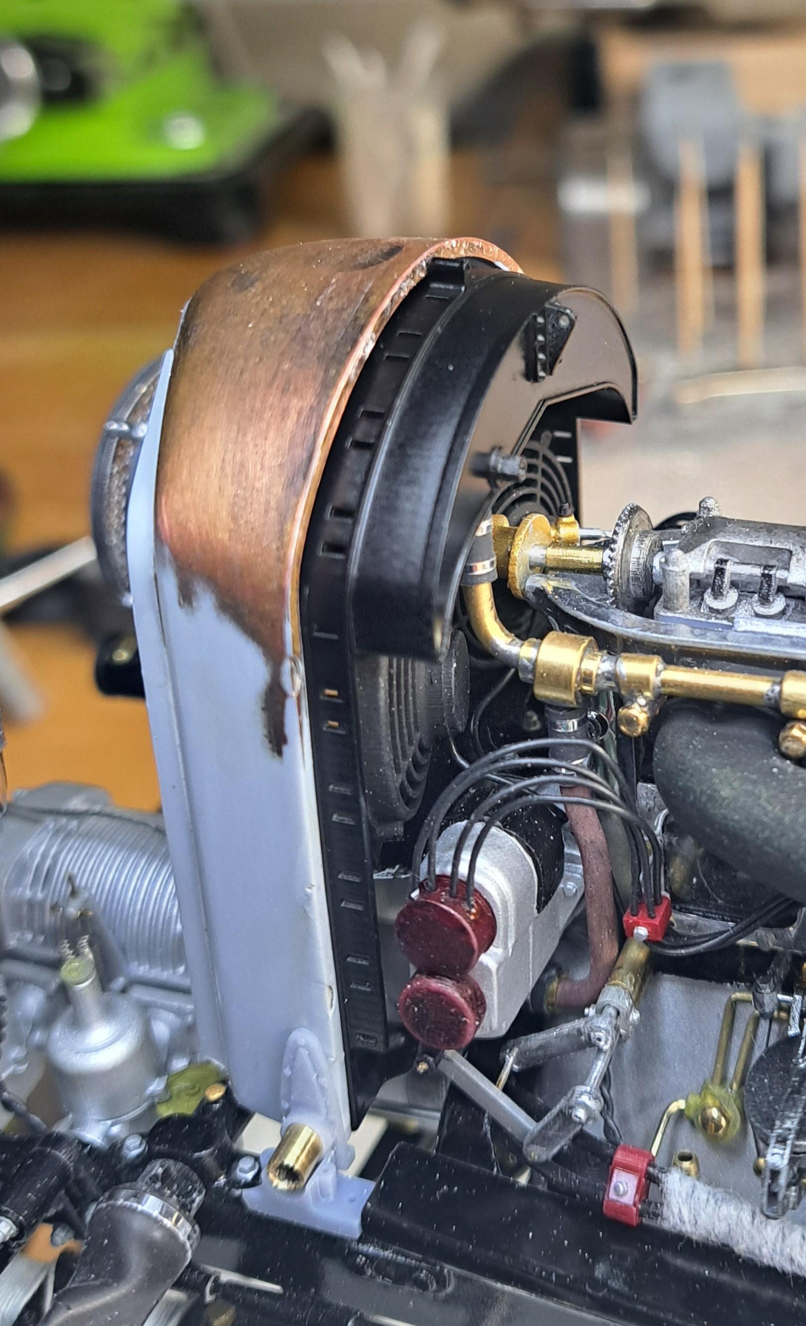
Ok so, the radiator fab is all done. The new logo and filler neck are glued on, the front grill is painted black and 'zeroed' in white. All that is left to do is to chrome it. But first, I decided to fit the hood. Now because of all the added details I did, I wasn't too surprised to see that the hood panels didn't fit. The added fans and better detailed water pump meant that I had to move the radiator assembly forward a bit. Combined with the completetly scratch built bulkhead assy meant that the hood panels were too short. Also, the more detailed magnetos did not align with the bumps moulded on both side panels. So I first removed the bumps and opened up the holes to better fit the new magnetos. I printed and glued on new larger bumps and added some styrene strips at both ends to lenghten the hood panels. There is still some fitting to do but it looks promissing. Side panel before mod After cut-out and added strips New bumps in place Trial fit I also stared the hood hinged
-
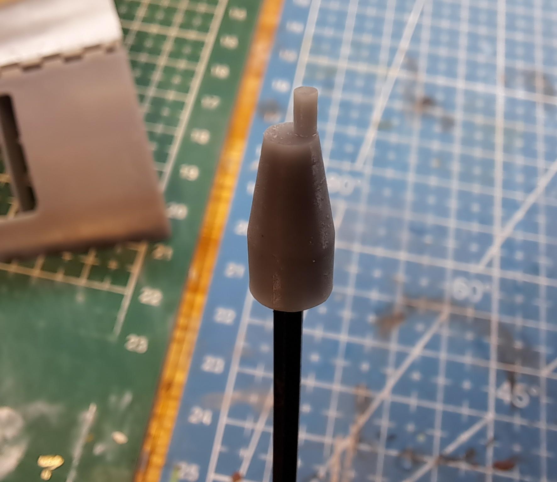
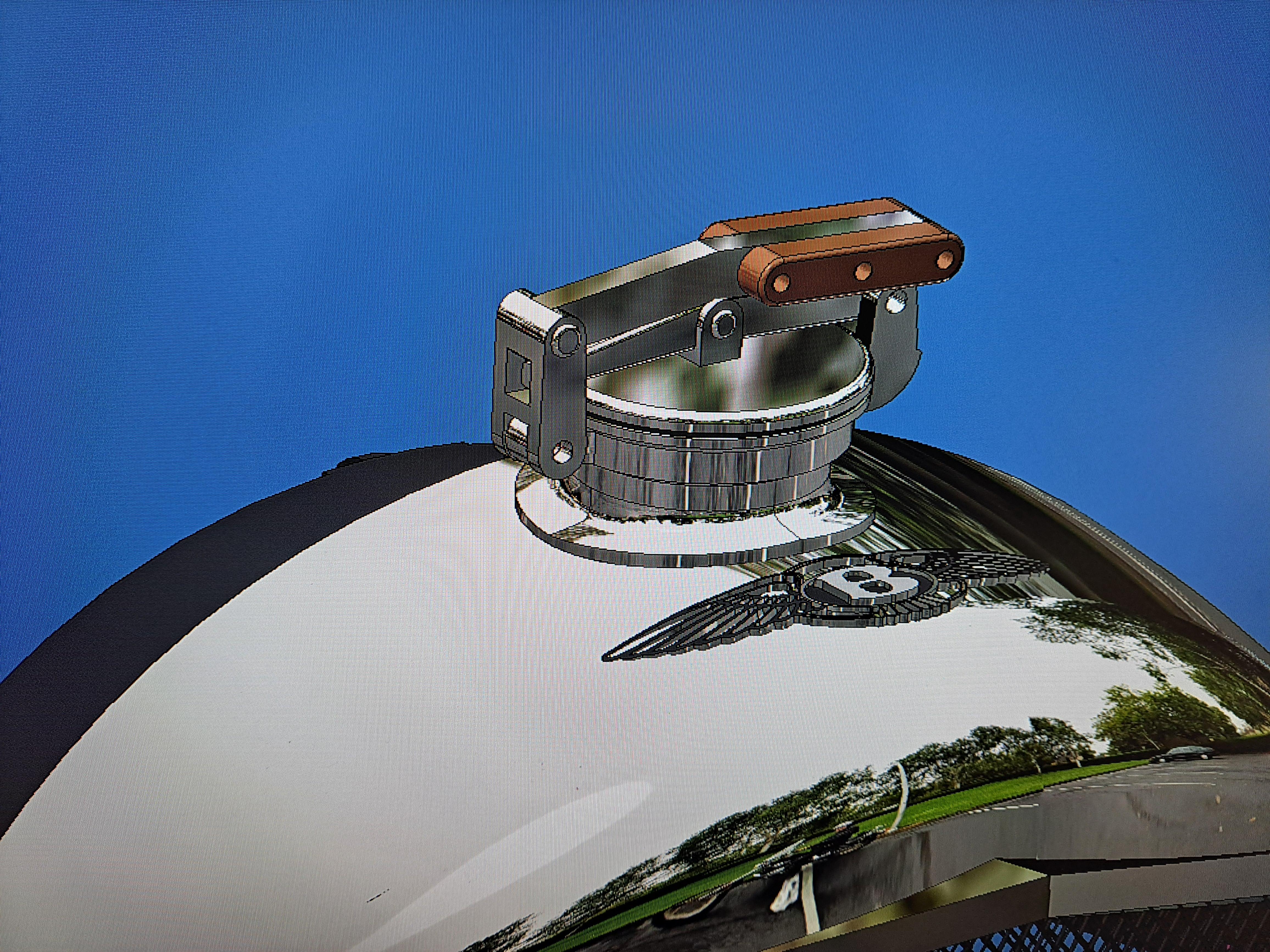
Thanks Bugatti fan Yes, I'll use the revell chrome. But once it's painted, I'll have to be very careful because this chrome rub off easily. Did the final print of the radiator cap and it turned out good. I also removed the logo from the front of the radiator cover and will glue on the new once I finish prepping the cover. Cap closed Handle opened Cap fully opened Radiator mounting bracket installed Getting ready to paint the '0' on the front grill Radiator to bulkhead link bar And a bit of cad vs reality
-
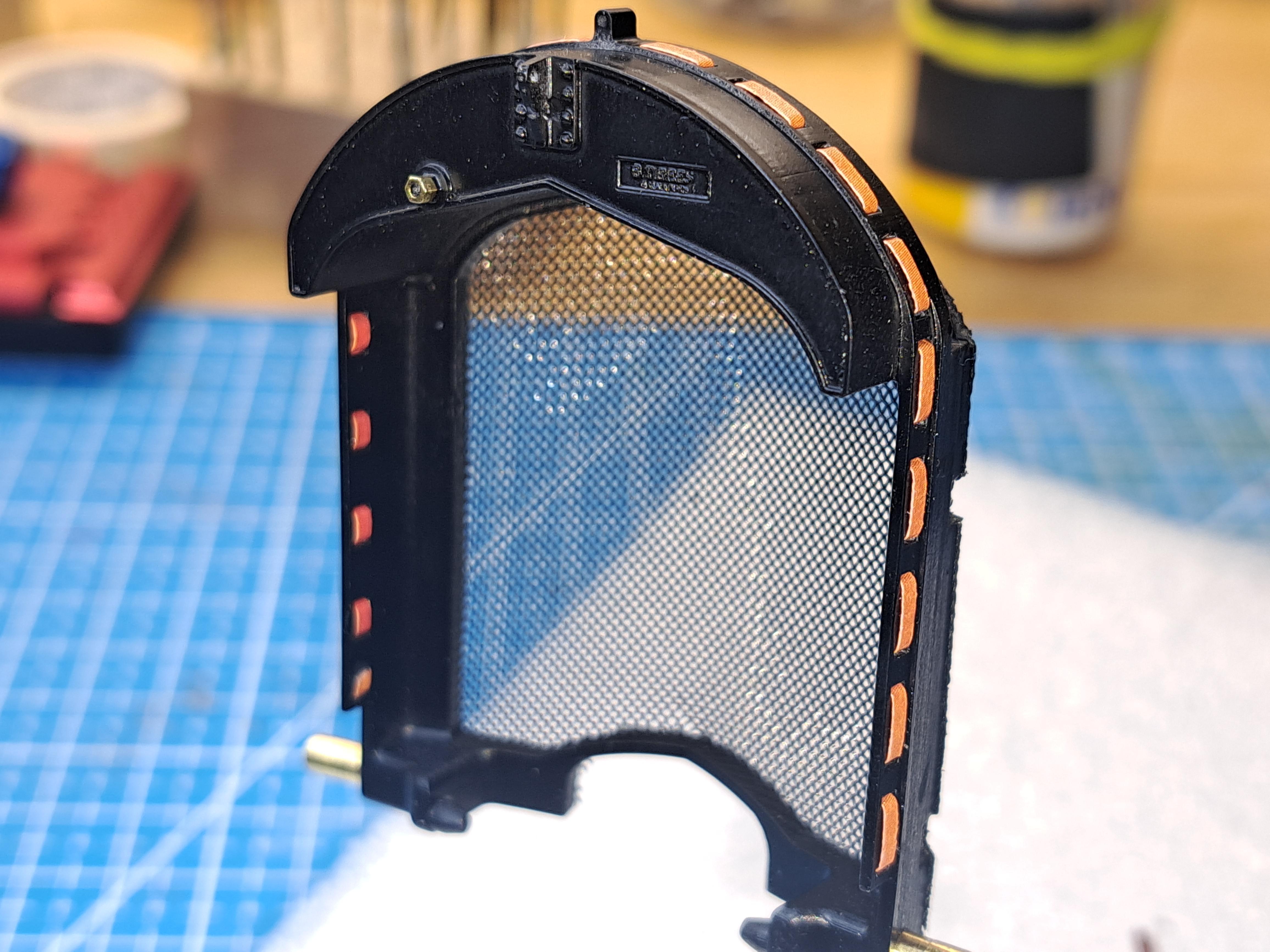
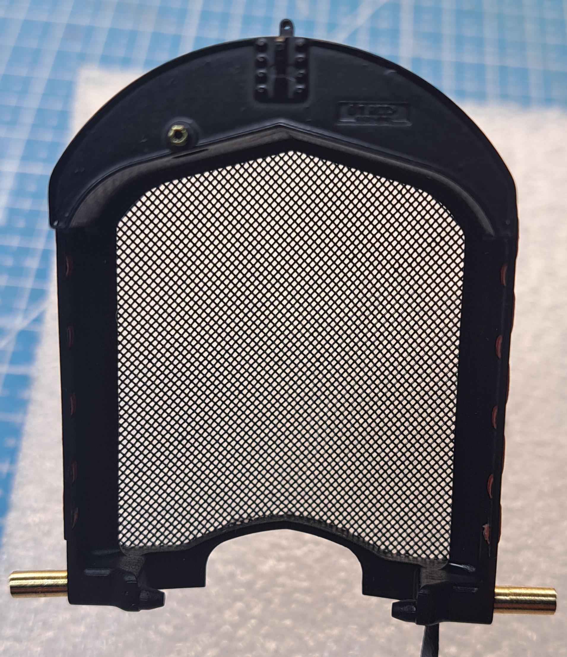
Thanks Bugatti, both for the comment and for the push. Once glued in place and chromed, it should effectively look better. I 3d modeled the radiator cap and am trying to make it operational but so far, the print results are not to great. I haven't said my last word on that one. I also installed the wire mesh on the front grill frame, took me 2 tries but I'm happy with the result.
-
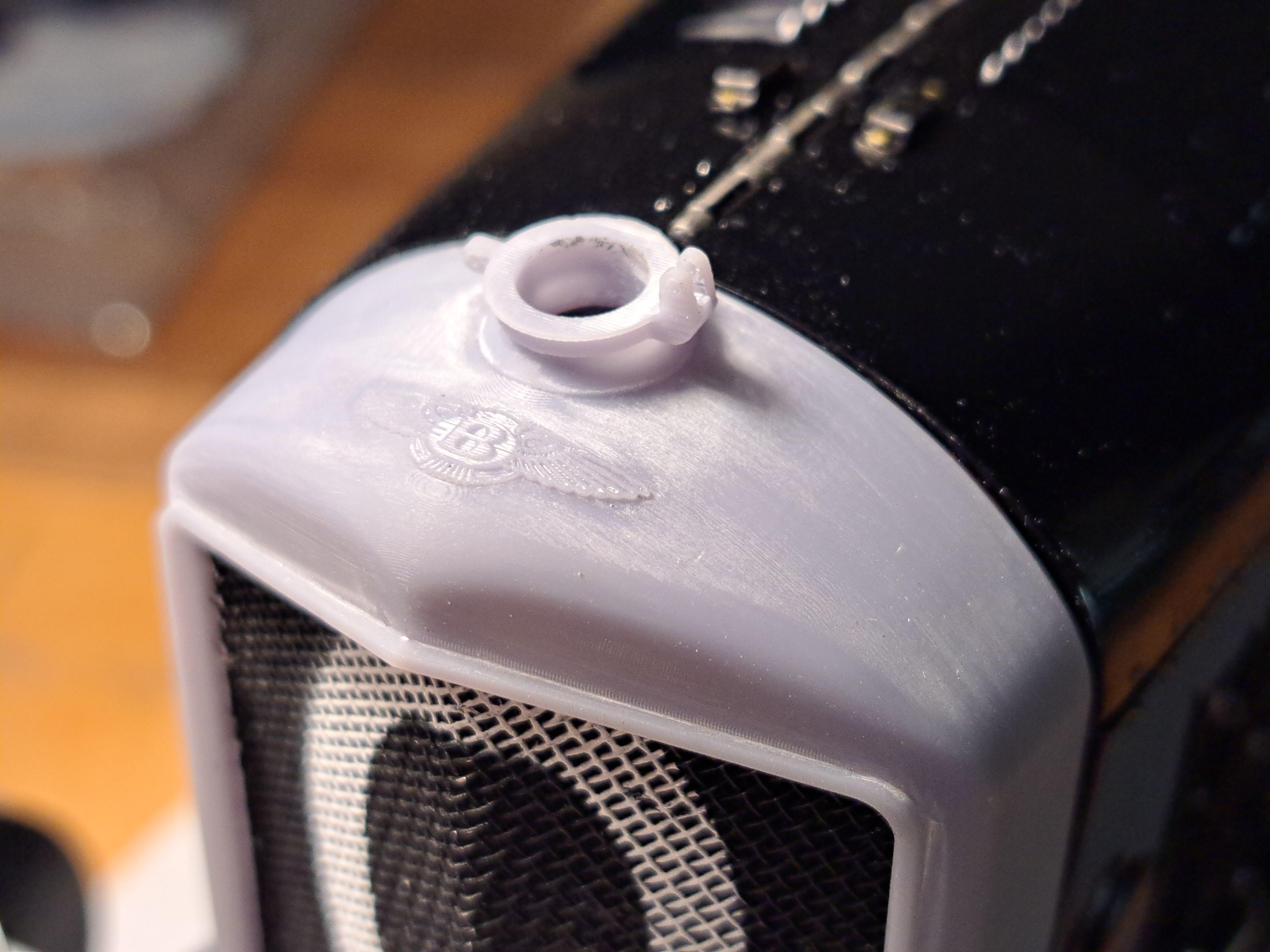
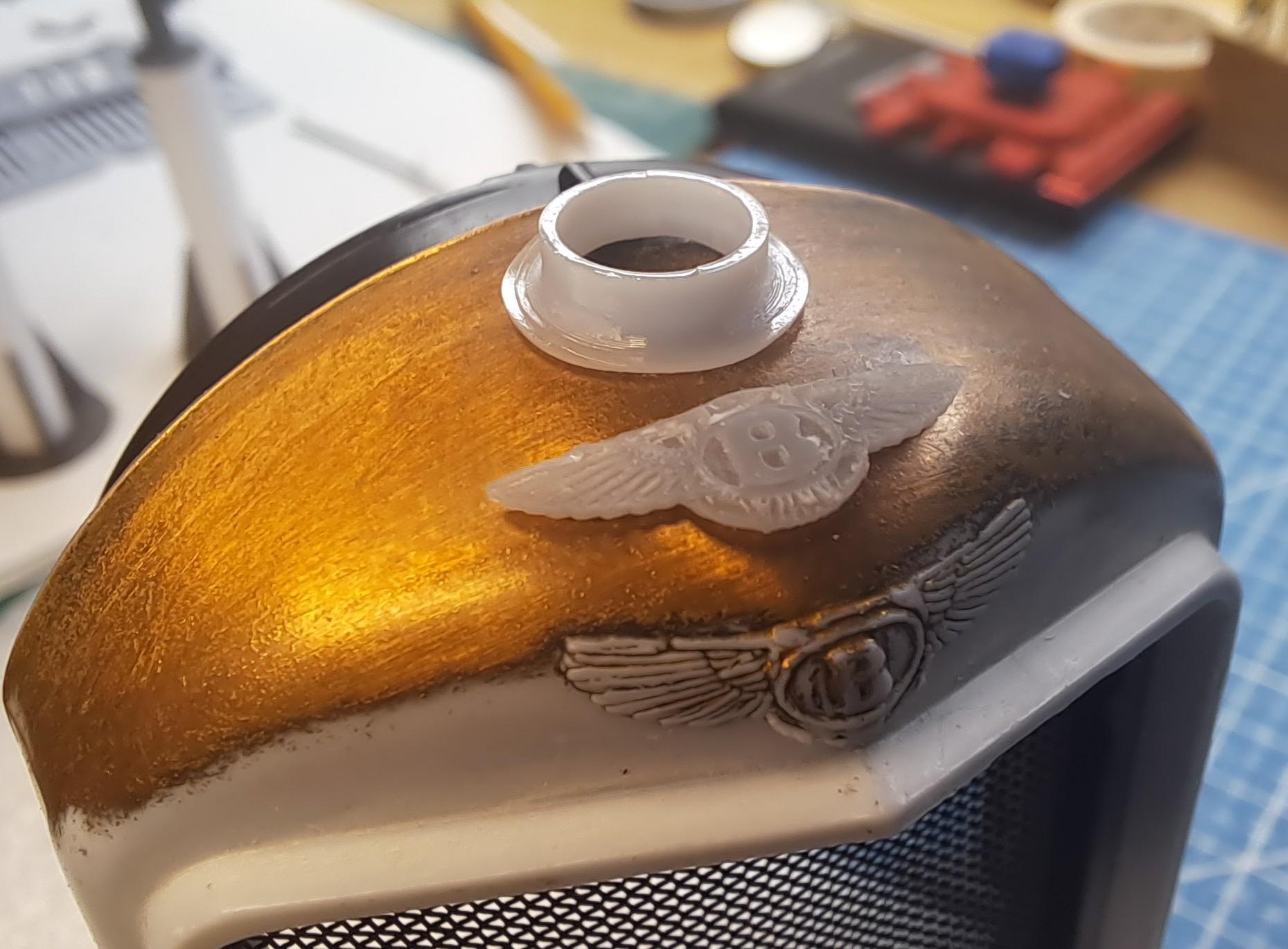
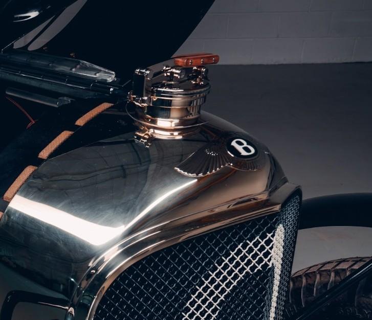
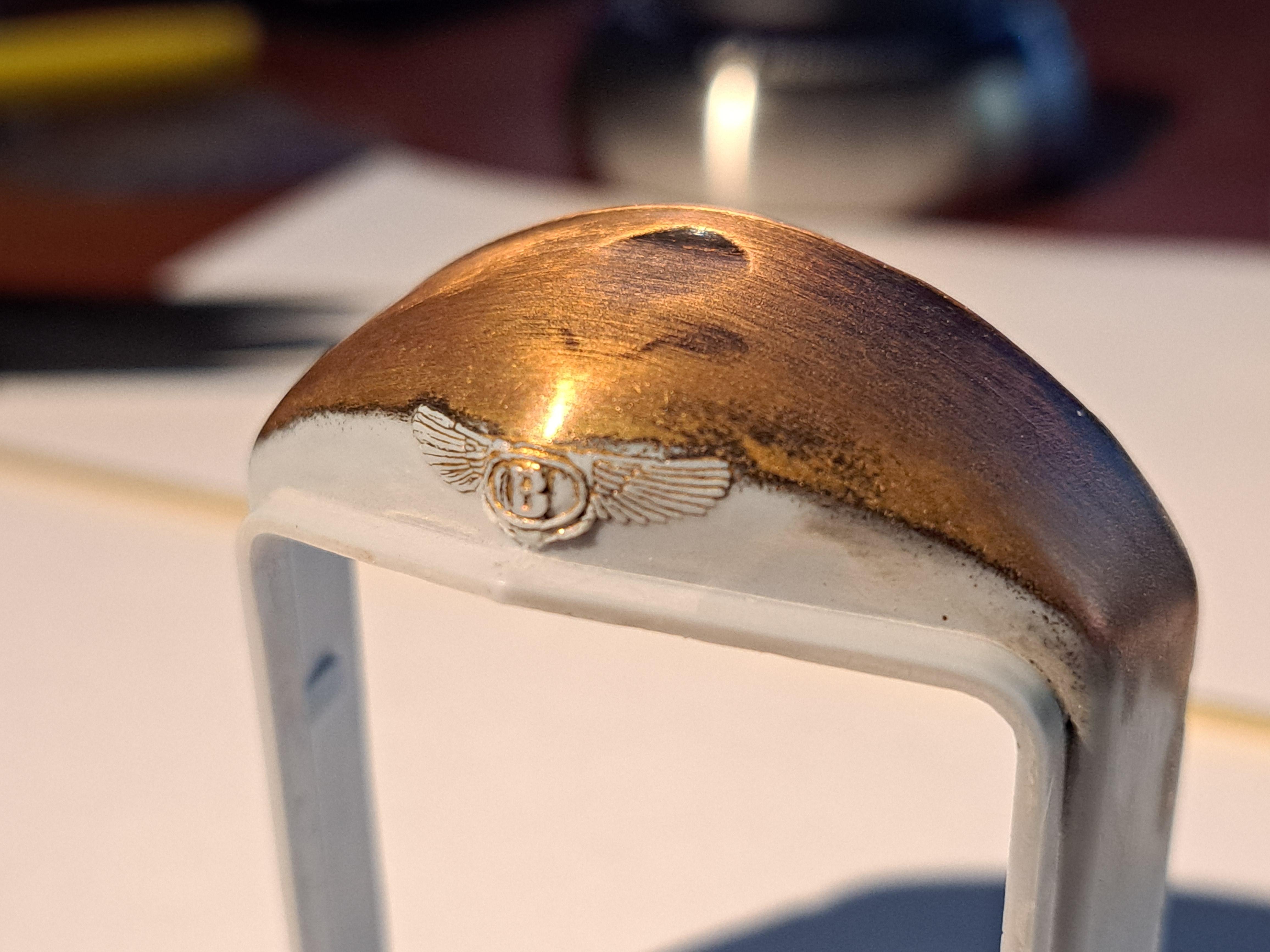
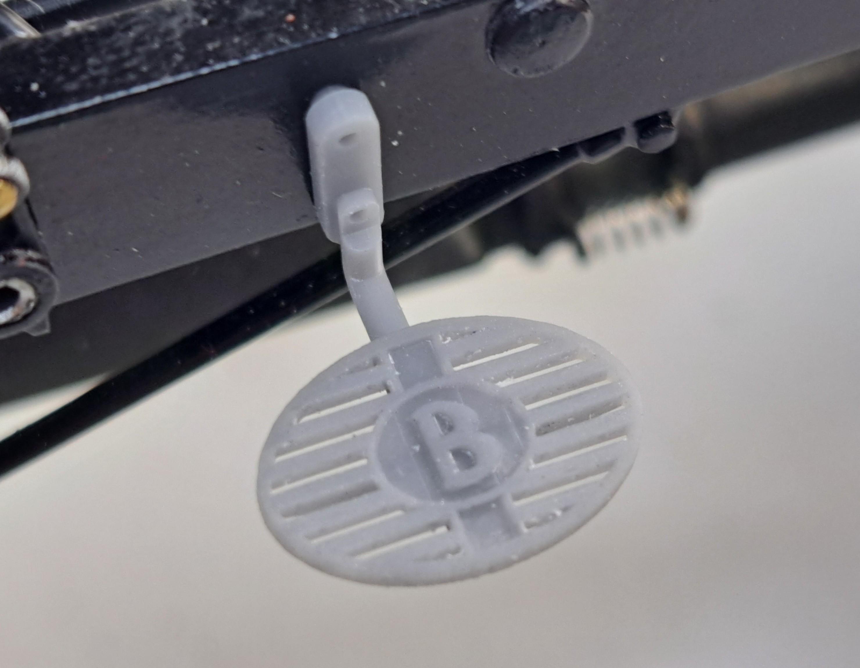
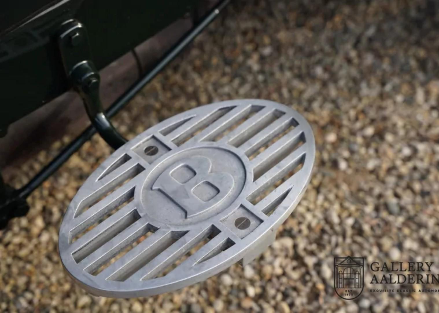
So, I was out skiing today when Bugatti fan and absmiami 'decided' that I had to move the bentley radiator badge. I took every ski lift time to think of a way to do this, here's what I did. First I found a good 2d cad line drawing of the logo then using this 2d drawing as a sketch in my 3d software, I embossed the logo on a curved surface that has the same radius as the radiator cover After several maneuvers I was able to isolate the logo and got this After printing, I got this. I also printed a test spout. Still a bit of tweaking to do but I'm quite satisfied. Noting is glued yet, once glued in place, the fit should be better. And the real thing So I think it safe for me to remove the kit's logo and replace it with the new better positioned one
-
Boy!! Talk about peer pressure! Not being one who backs out of a challenge, I'll give it a go. I'll first try to 3d model the logo and print it. If and only if this works will I remove the badge from the part.
-
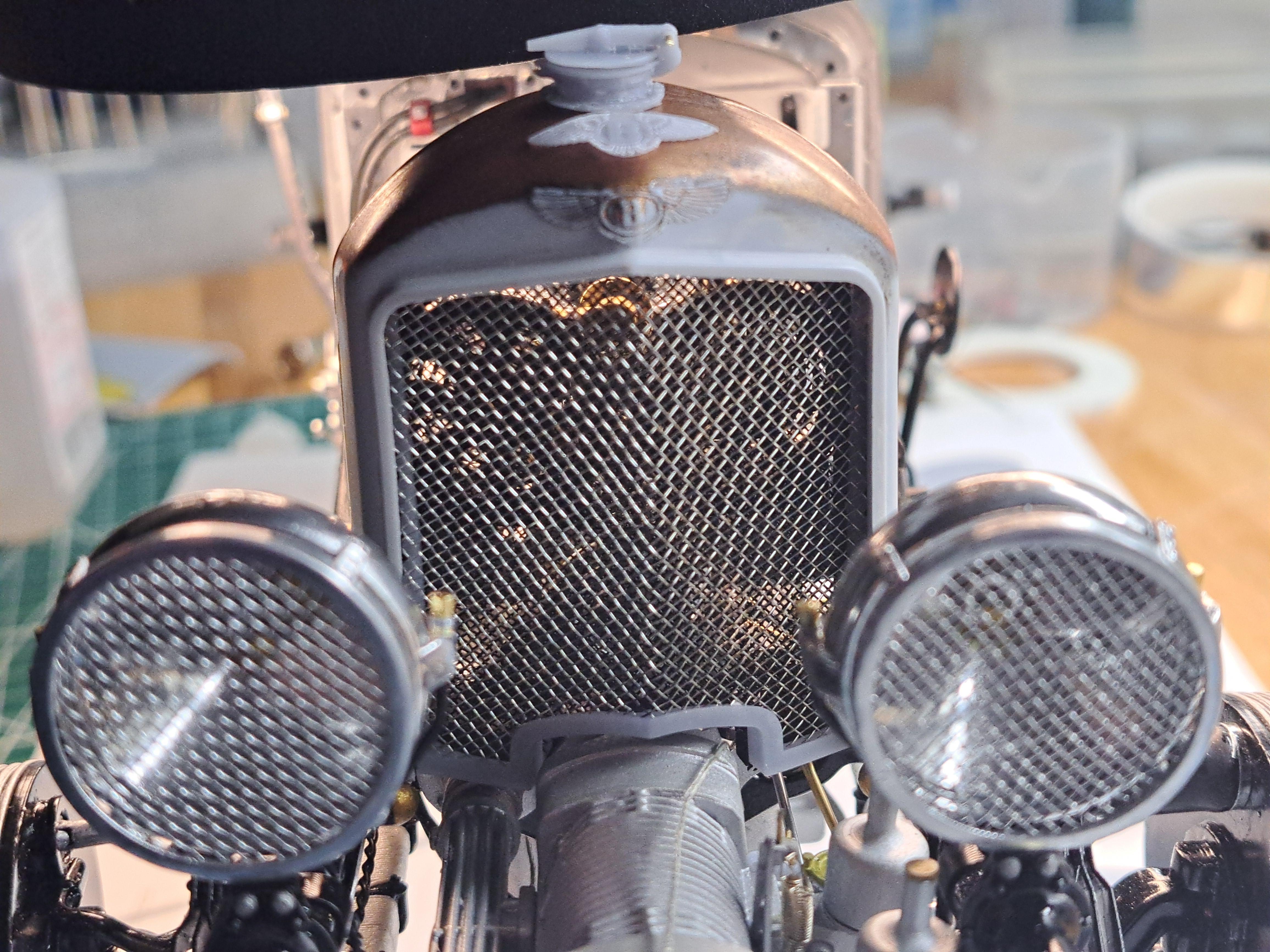
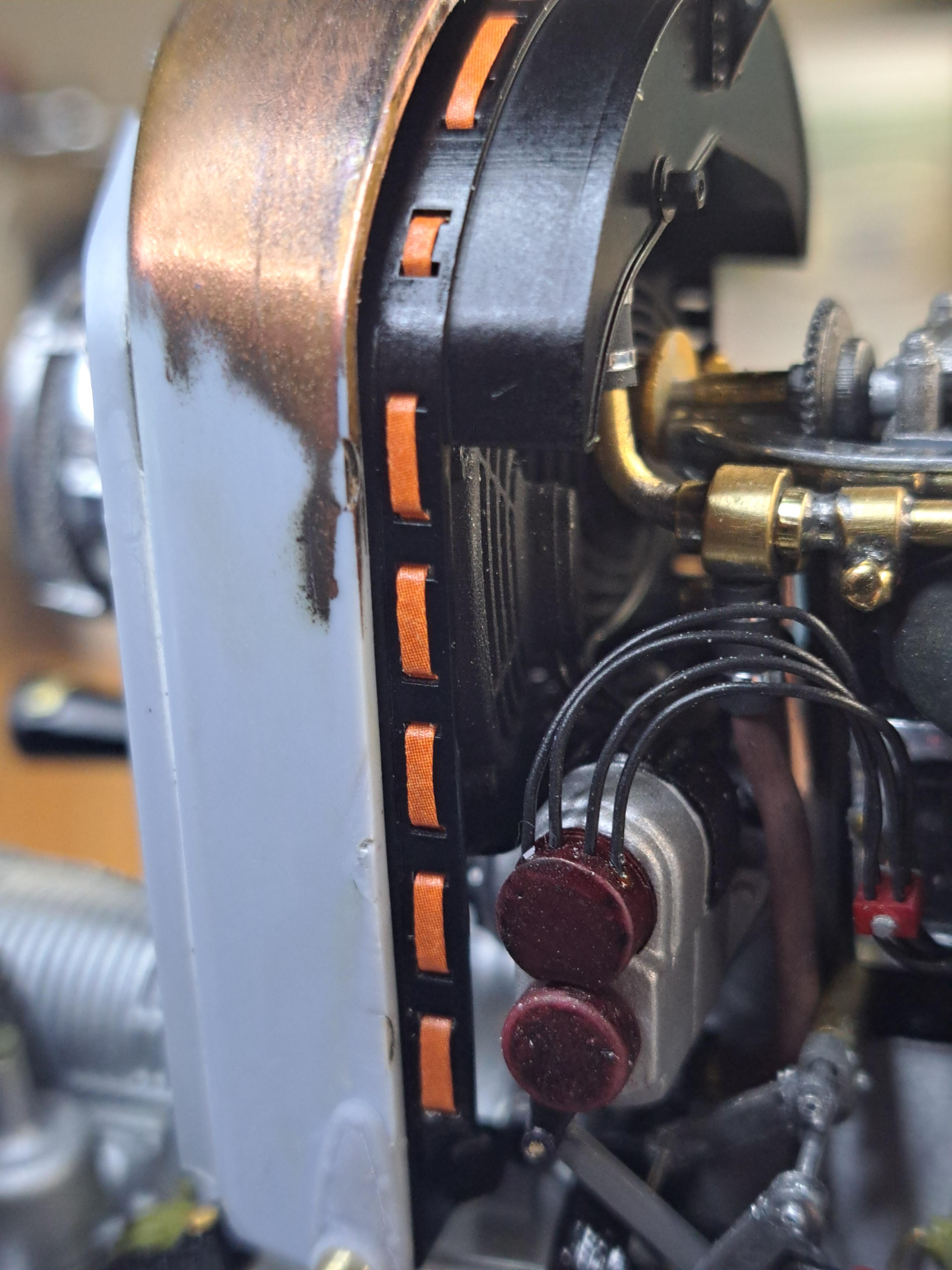
Reprinted the radiator core and this time I got wedding patters right. And since I was reprinting, I added a small name tag. I'm not sure it's on my ref car but it was on a picture of a new core I have. I also installed the wire mesh. Naturally, unlike mine, you would't see thru a real core. But I kinda like it like this since the fans and water pump should be fisible from the front grill. I did a test with the front grill, not quite there yet but it's promissing. Here's a real core And here is mine the real webbing And mine And the name plate Front grill test
-
I had pretty much finished printed the different components for the radiator assembly when I noticed I made a mistake. Here's what I did wrong. There is a type of webbing inserted in small slots that goes all around the core's outter flange. Here's what I'm talking about. When designing the core, I missed one of the slots for the webbing, the result is a broken pattern. I'll reprint it. The rest of the parts are ok.
-
First test print of radiator core, not half bad. I'm still missing some details but at least I know it prints ok. I'll be using a very fine flexible wire mesh that as an aperture of .02 which should simulate the core's mesh pretty good. For the front grill, I'll use the same metal mesh used for the head lights.
-
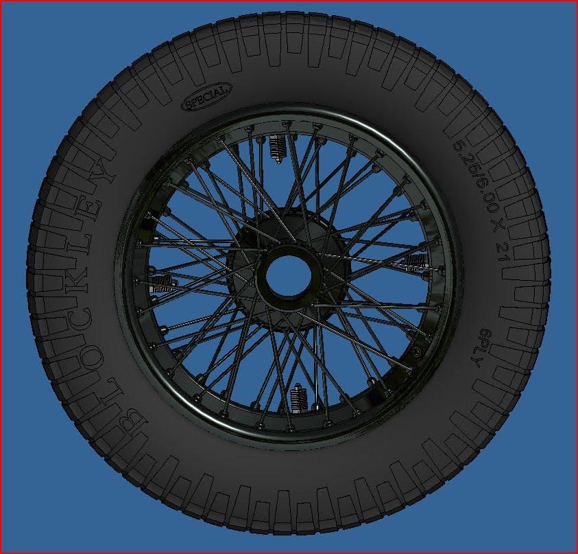
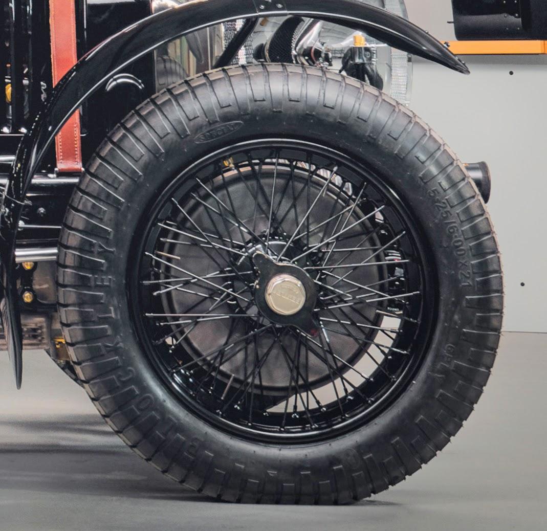
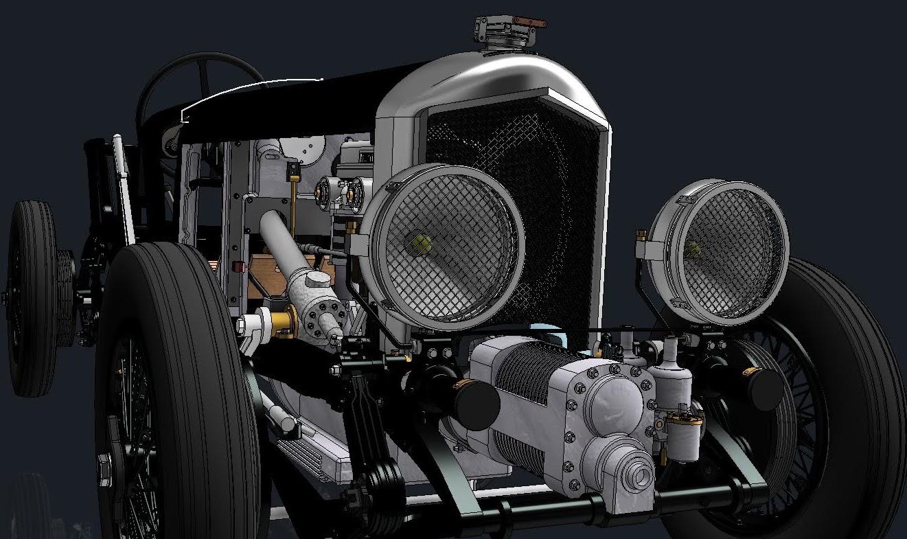
Thank you all for the positive comments. Finished reenforcing the head lights assy, shouldn't brake anymore. Now that that's done, I decided to tackle the radiator. The kit's radiator is composed of 3 parts: 1-the inner part that represents the core (right), I'll completly replace this part because it not very detailed and it doesn't fit with the twin fans and water pump. The kit's core with the grill removed A real core My core so far 2-The outter shell (center). I'll keep the kit's part but will replace the poor excuse for mounting brackets that are there by more accurate looking brackets. The kit's bracket Real thing First test print I know that many say that the bentley badge location is incorrect but personnaly, I don't find it too bad. I think that playing with it would only make it worst since this part will be chromed. 3- the grill, I will also redo this completly As a side note, I was recently asked to 3d model and print a model T tire in 1/25 scale complete with the firestone logo and a specific thread. This is what it looks like And a vintage light. Again in 1/25 scale. The post holding it is a toothpick!! This was a mis printed part that I painted real quick just to see the color scheme
-
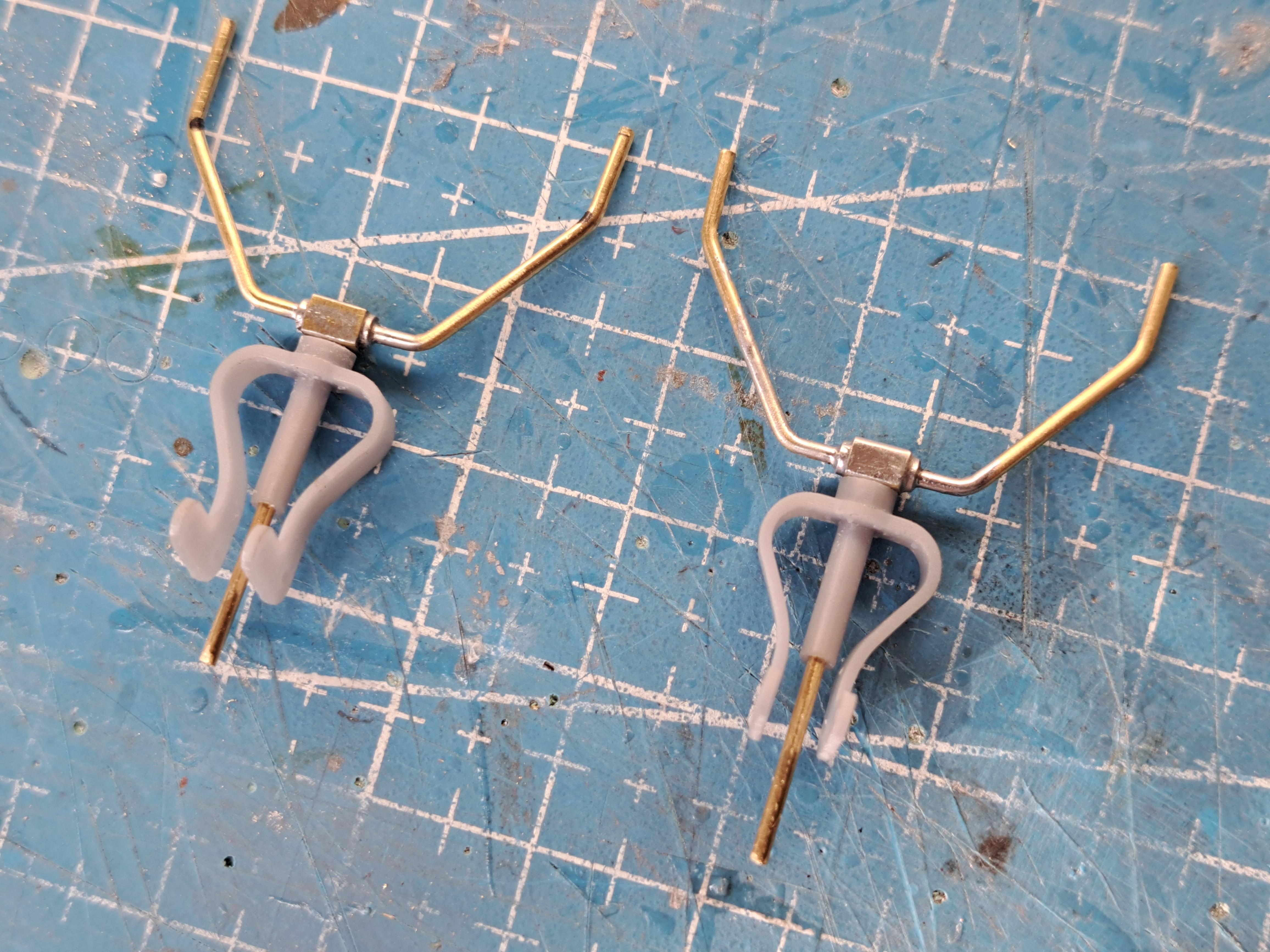
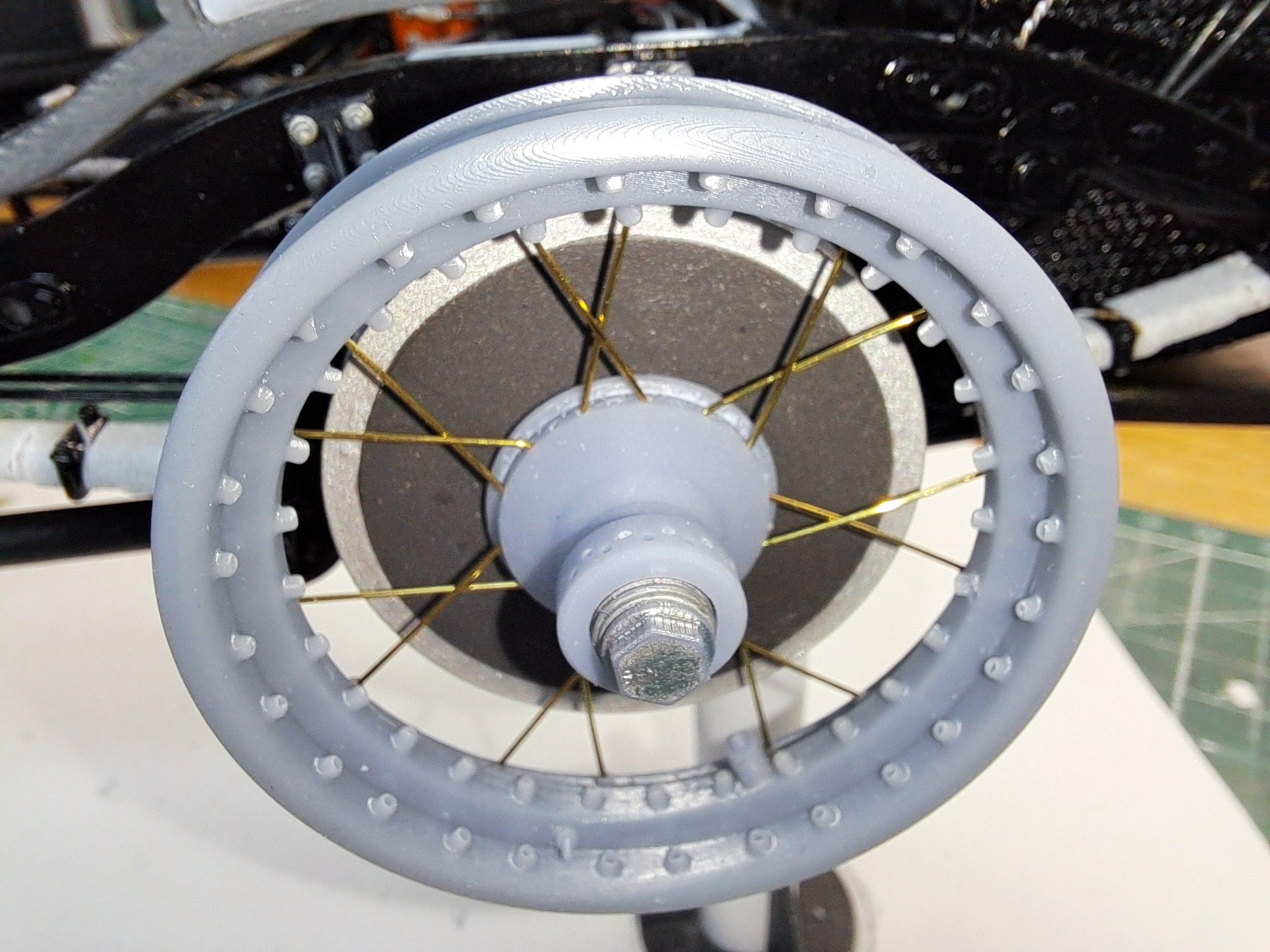
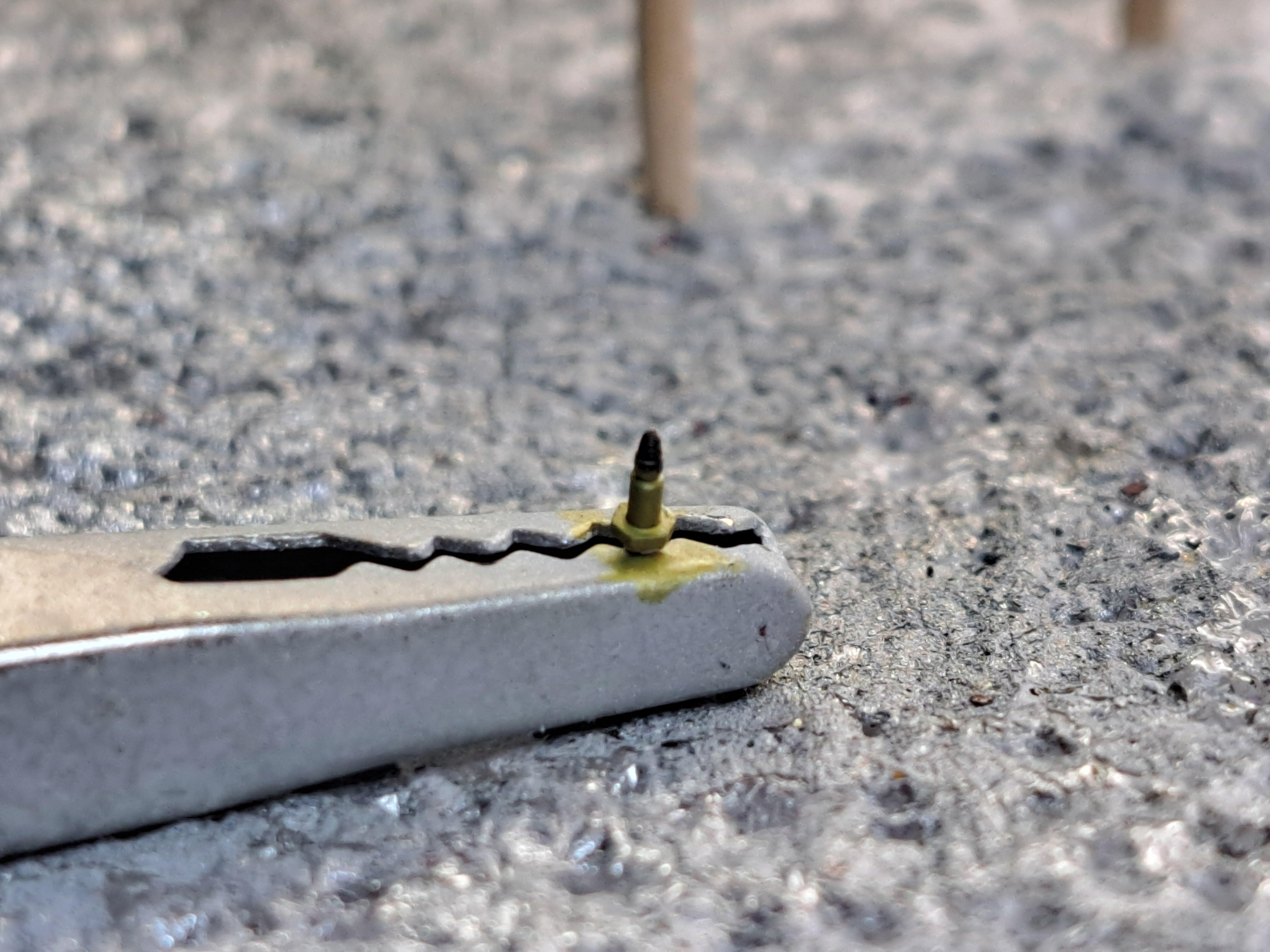
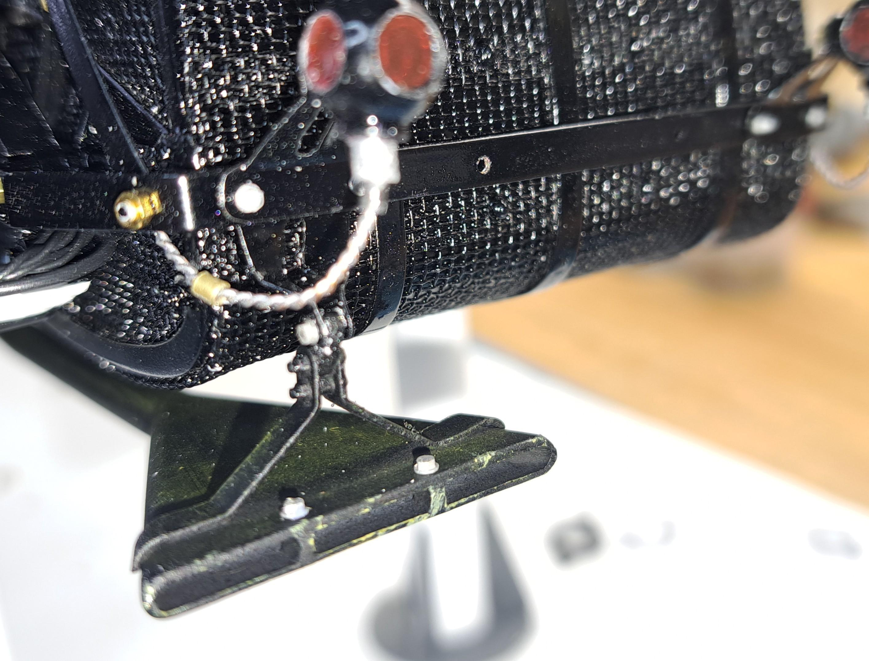
Had a bit of bad luck with the head lights assembly. The 'U' shaped bracket that holds the head lights is so fragile that it keeps braking. So I did what I should have done in the first place, I made it out of a brass rod. I had to slightly modify the horn bracket to have a more sturdy assembly. The new 'U' shaped bracket that is now more a 'Y' is made of soldered brass rod, round and square brass tubing. The lower rod will go thru the modified horn bracket and also thru the frame. I also made the spare wheel mount with a screwed on center spigot for easy spare removal And the real thing And lastly, l made the step. I might need to rework the shape a bit but it pretty close. This is the kit's step Mine And the real thing I'm also slowly advancing the lacing of the wheels. I've pre-painted all the hubs and rims First layer Second layer Third layer
-
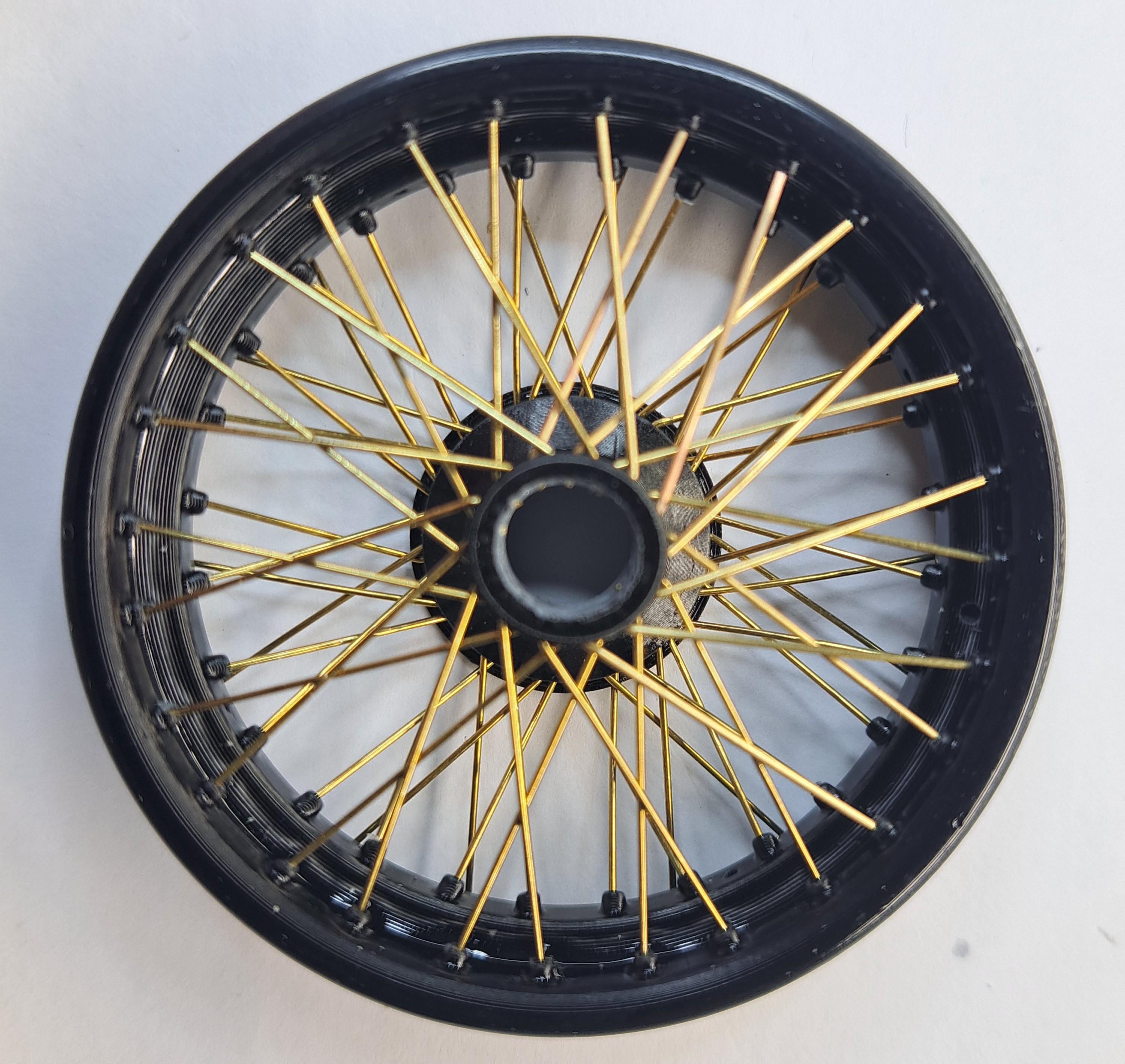
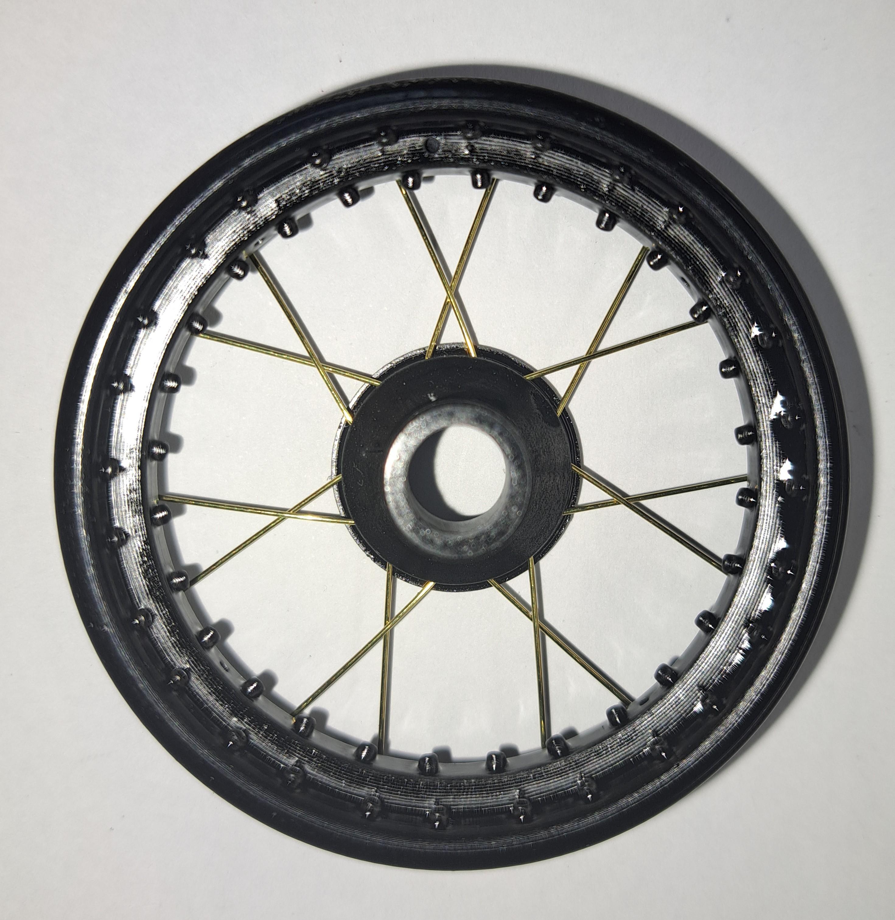
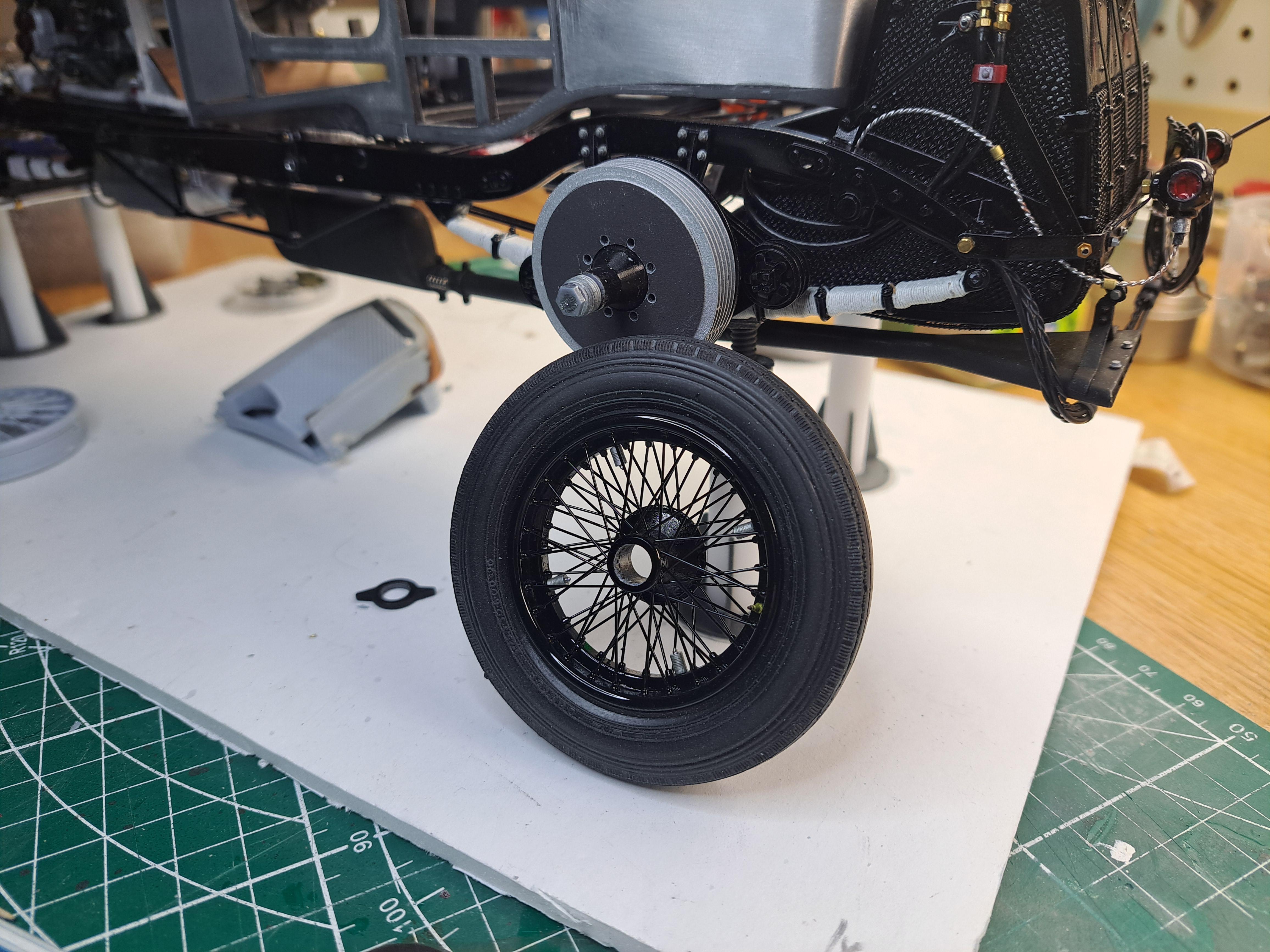
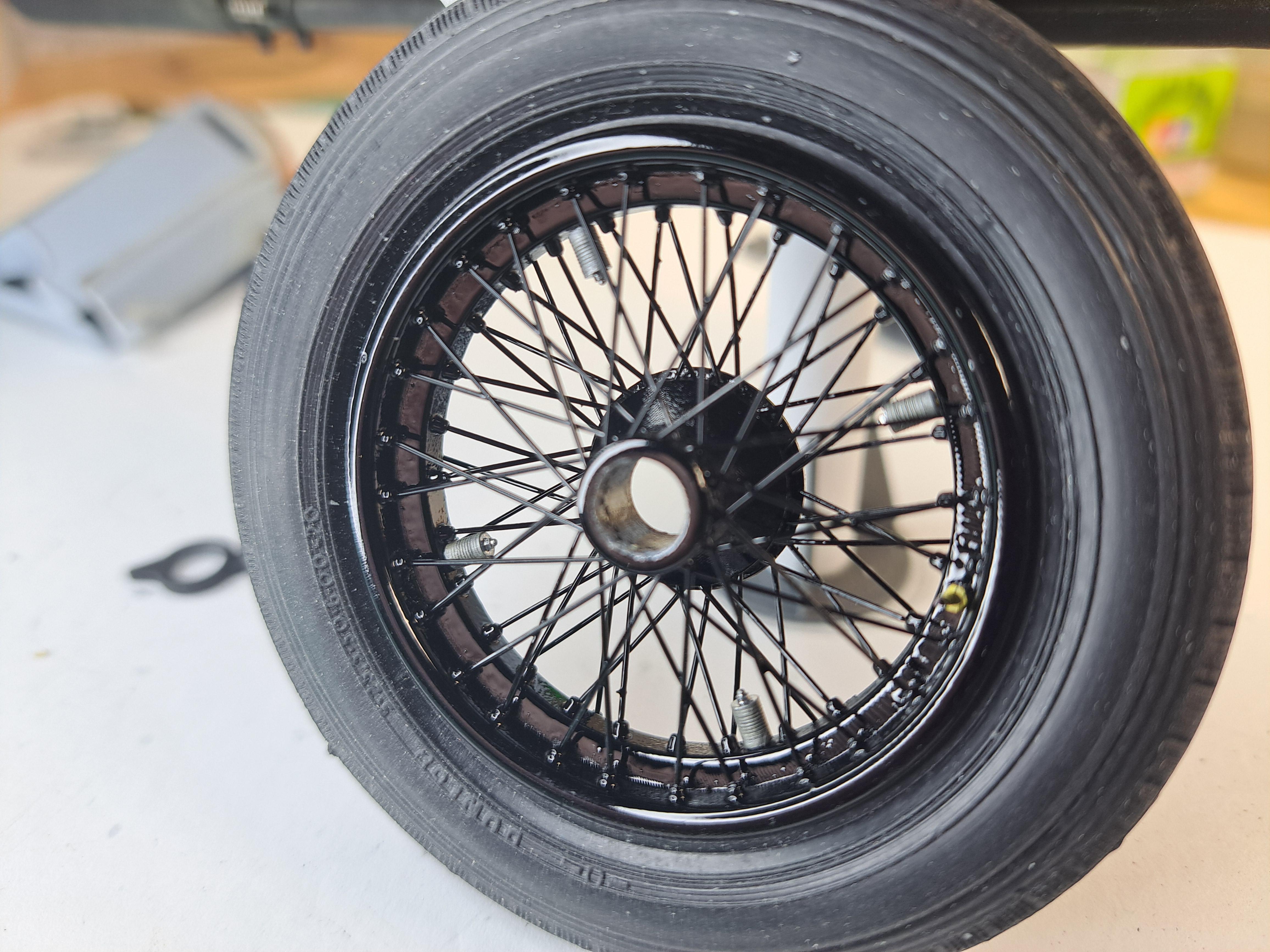
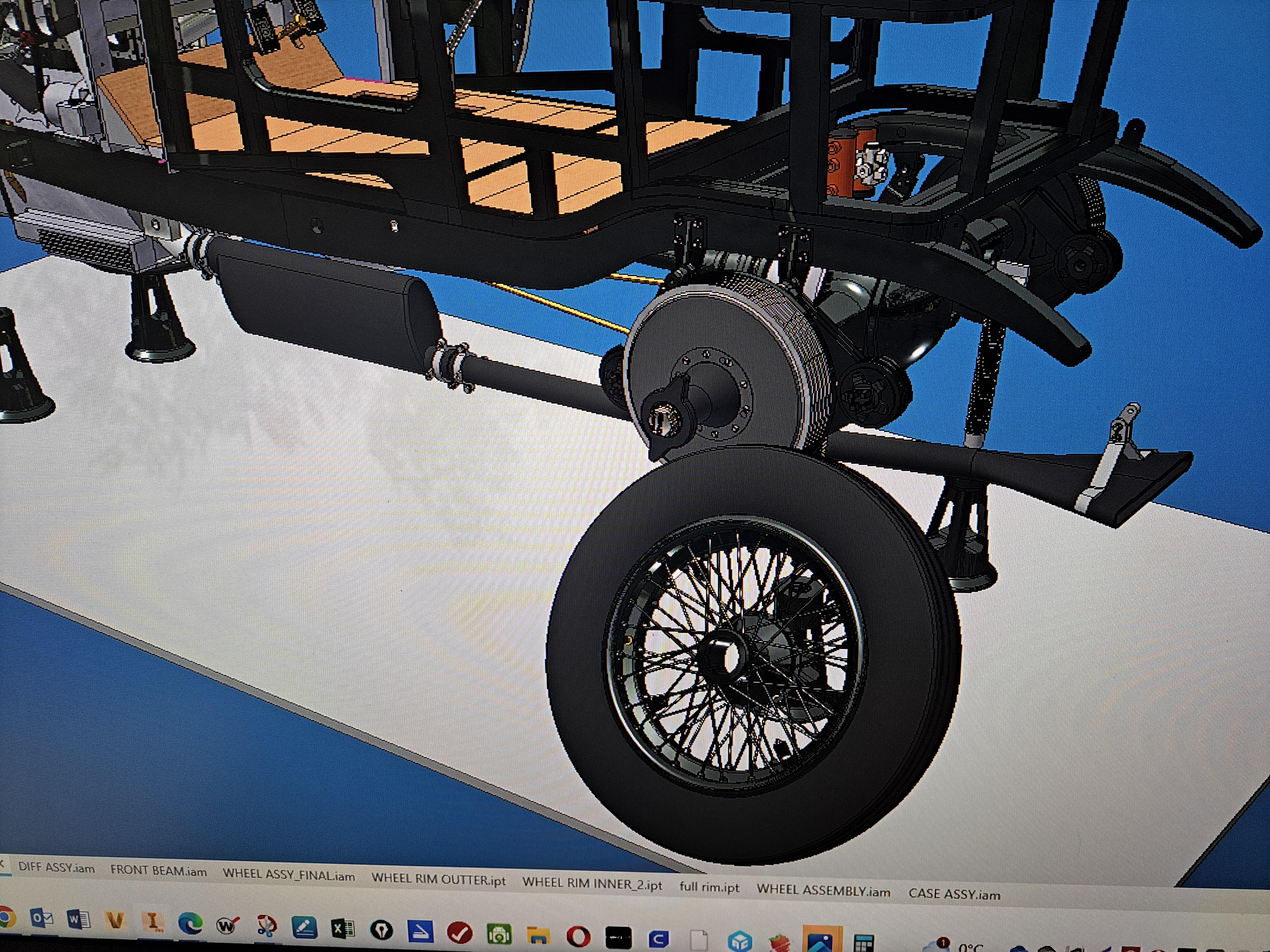
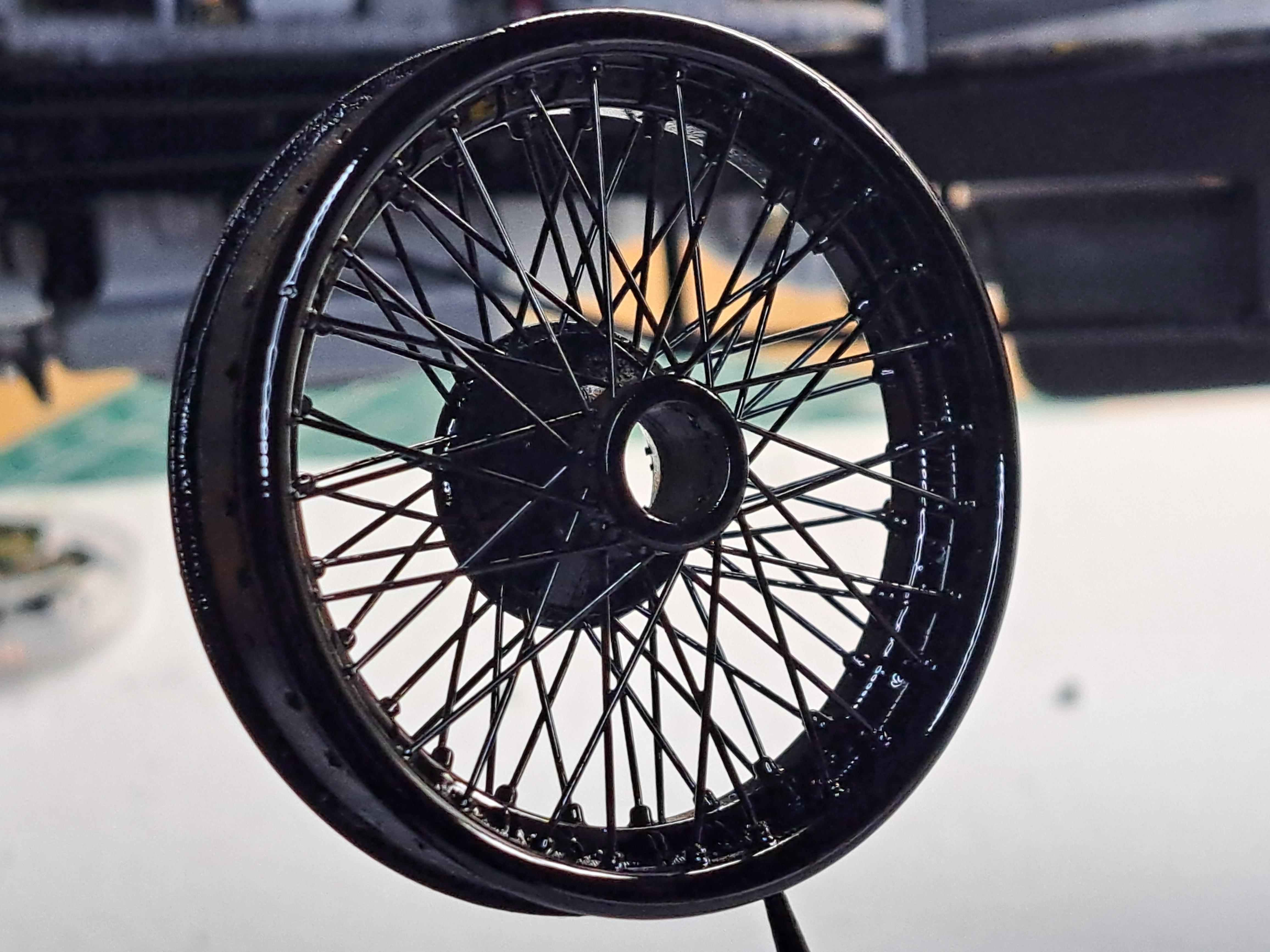
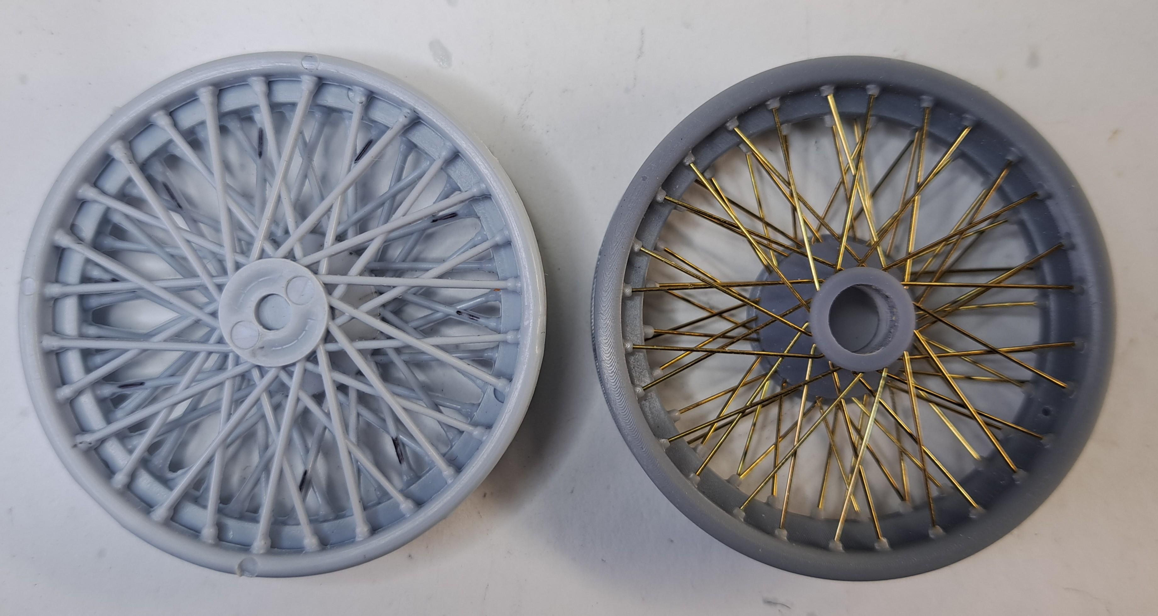
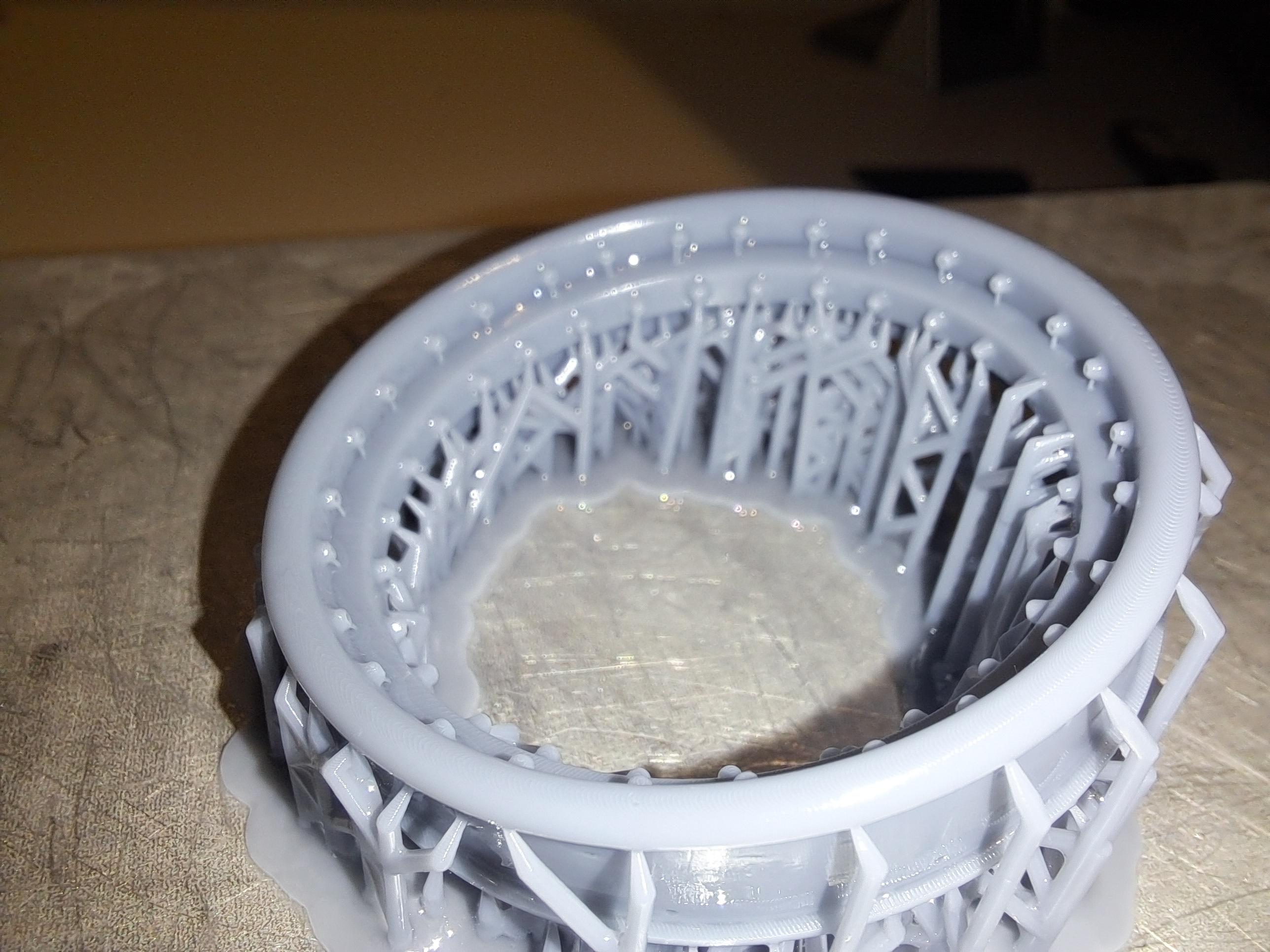
Like mentionned on my previous post, I tried printing the wheel rims instead of drilling the ones from the kit. Well after a few printing interrations, I'm very happy to say that I was able to print a very nice rim. The prototype rim (all the pictures that fallow are of that wheel) was printed at an angle, the finished rims are printed flat and the result is even better. So here are some pictures from start to finish with, as always, a few pictures of the real thing. The rim fresh off the printer, printed at a slight angle I made an assembly jig to aid the alignment of the first row of spokes First row done Second row Wheel completed next to the kit's wheel Primed And painted. The prototype was painted after lasing but the proper wheels will be painted in sections, the hubs and rims will get a coat before lasing and a final coat over the finished wheel. I believe that the result should be better this way. i also printed a valve And a bunch of wheel weights The finished prototype wheel The real thing again the real thing And for fun, the model Vs the cad model and a little video 20240110_212556.mp4
-
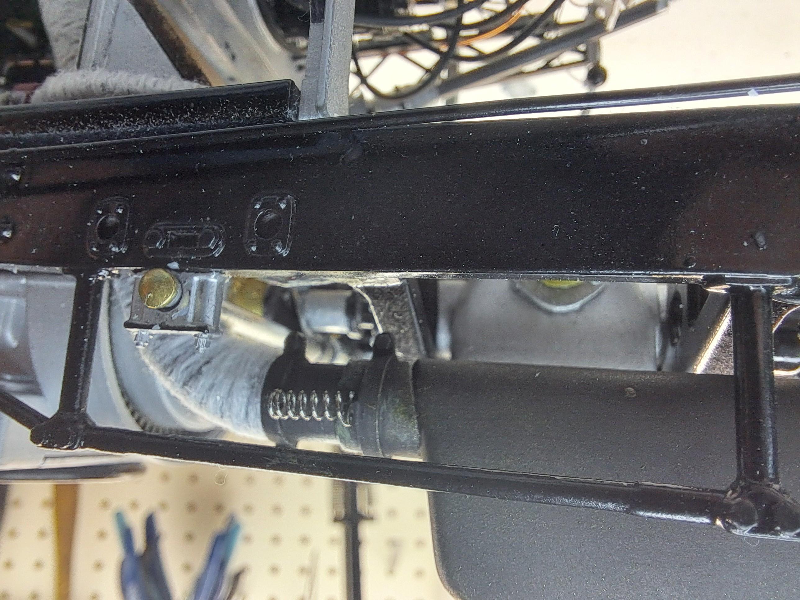
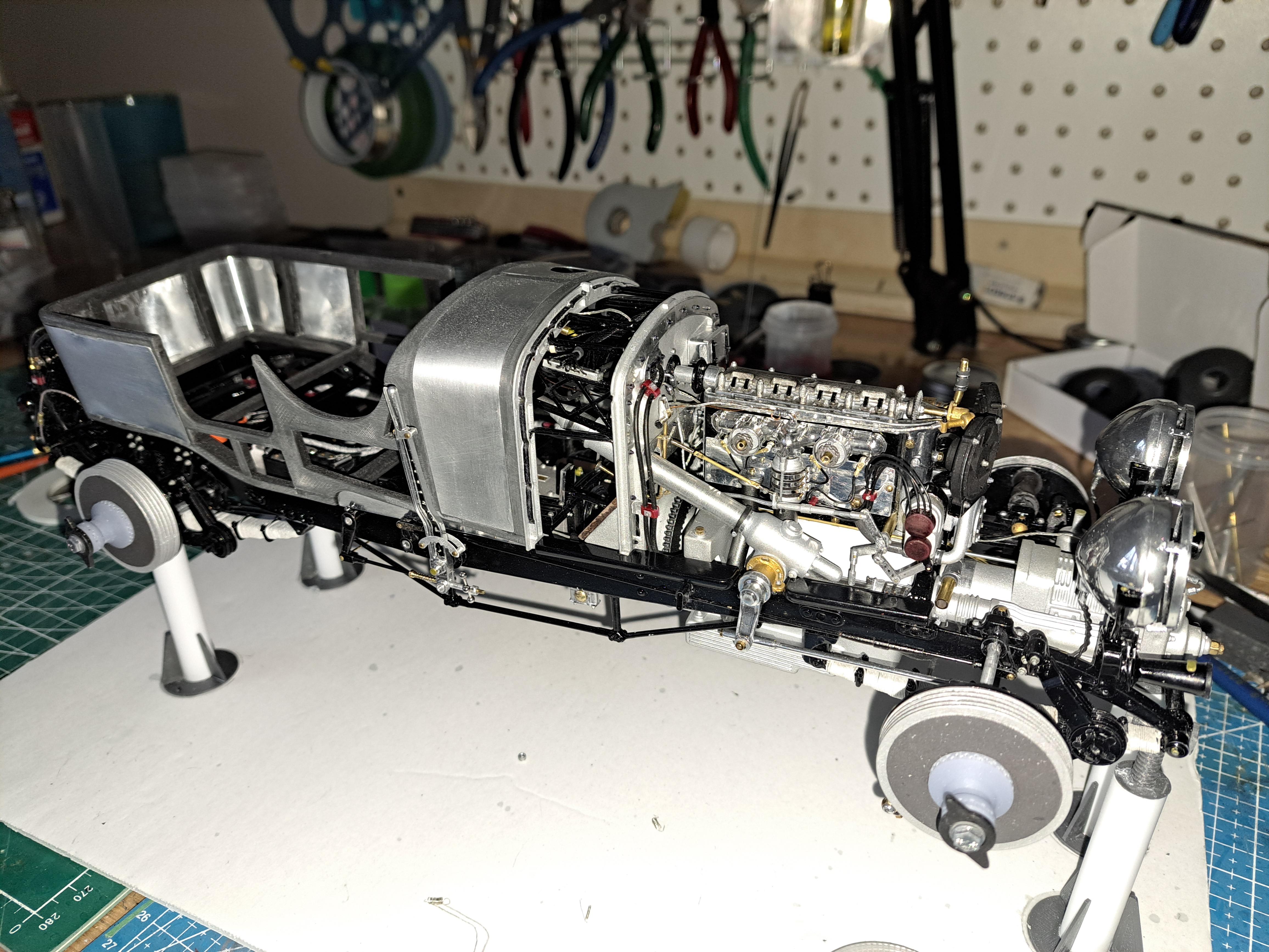
I did the exhaust system. I wrapped the down pipe, added tube clamps with expension springs before and after the silencer and added the correct tail pipe mounting bracket. The real thing Tube clamps and springs Tail pipe bracket The real thing I also decided to try my hand at printed the wheel rims instead of drilling a zillion holes in the kit rims. First try is promissing. And lastly, here are some general shots of the car with the body on