LOBBS
-
Posts
645 -
Joined
-
Last visited
Content Type
Profiles
Forums
Events
Gallery
Everything posted by LOBBS
-
I've been begging for a new tool '67-72 C10 for years. I cannot wait
-
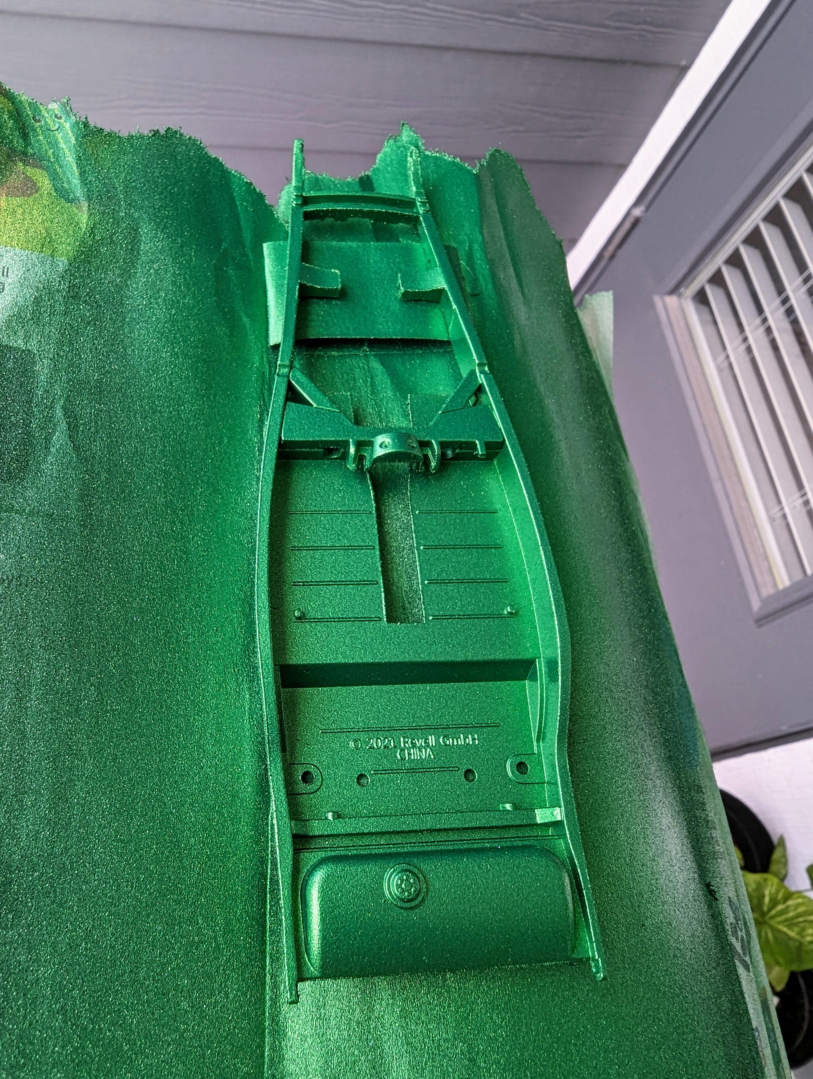
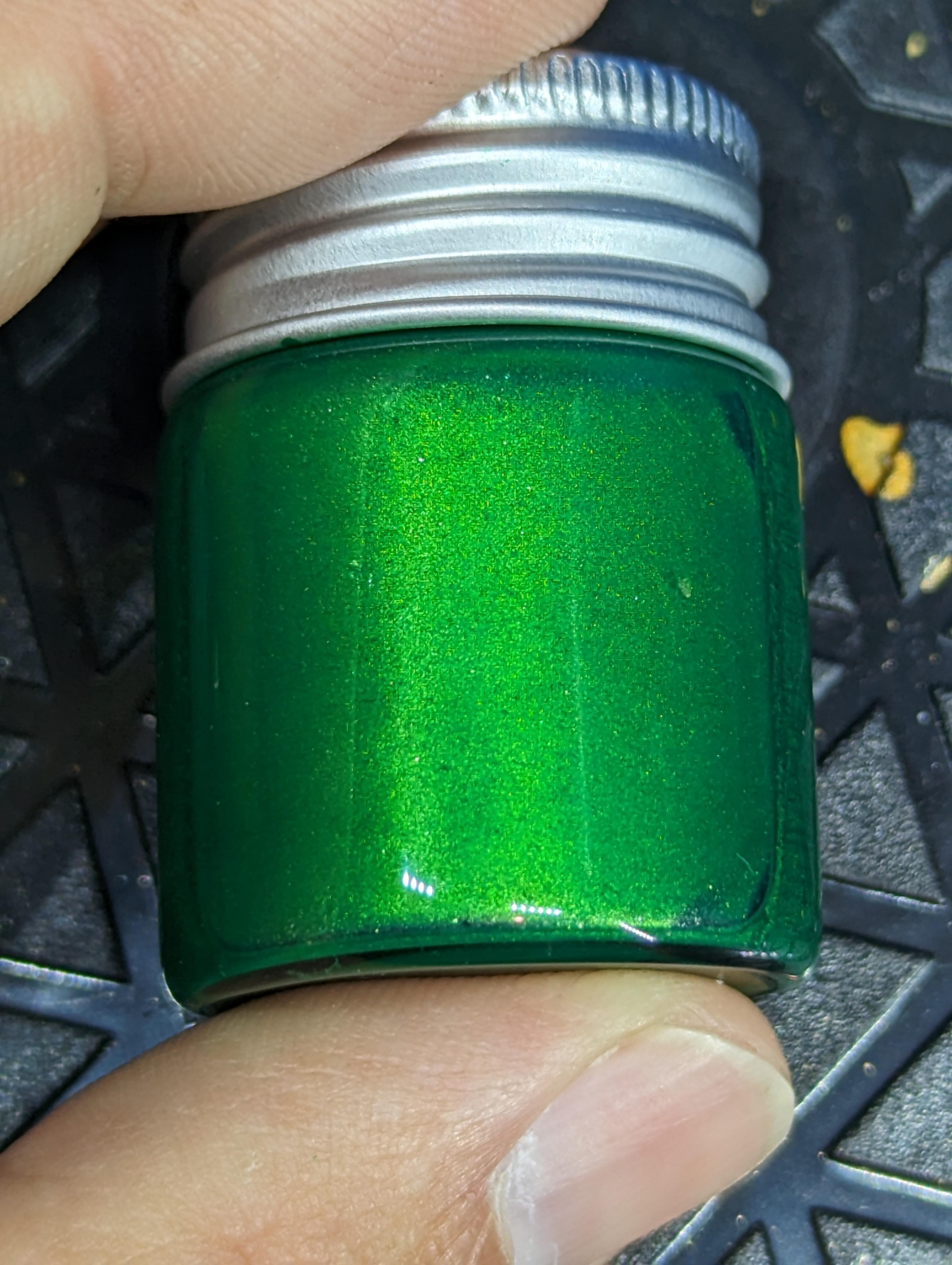
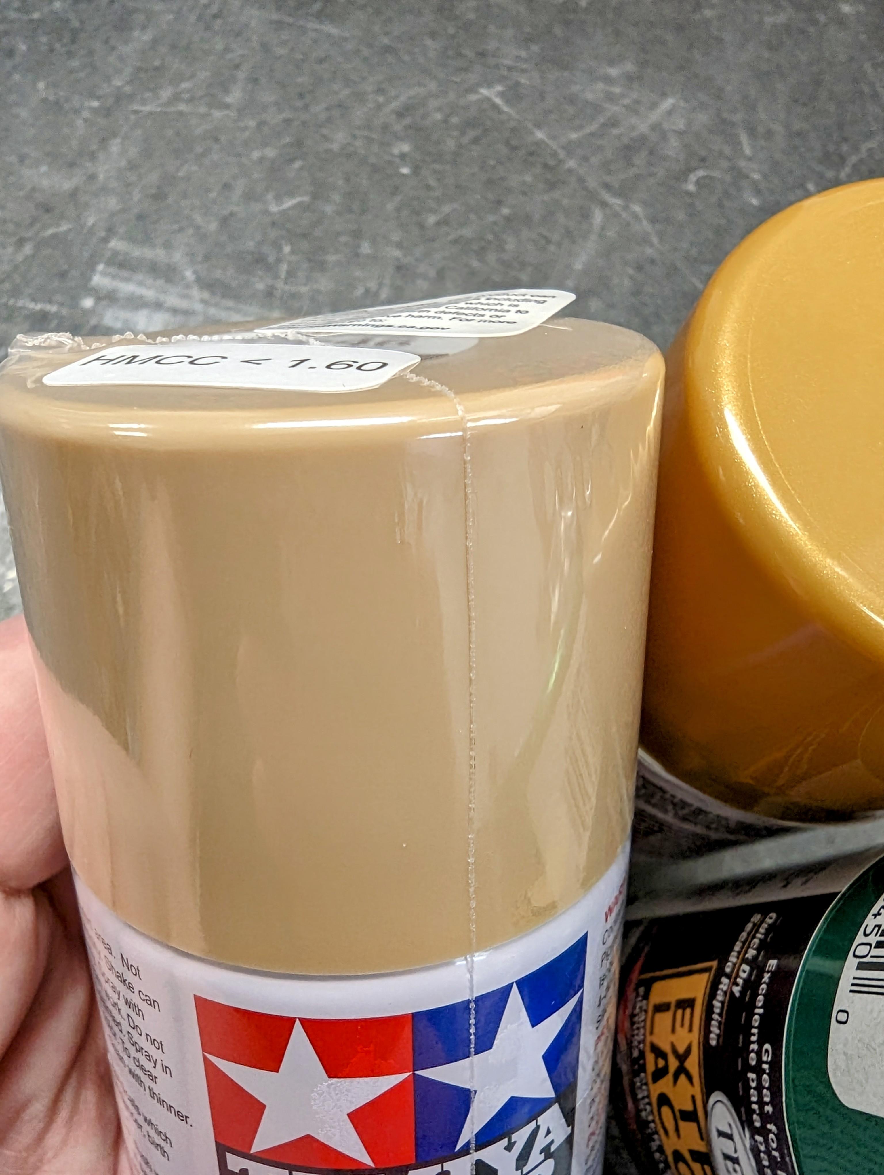
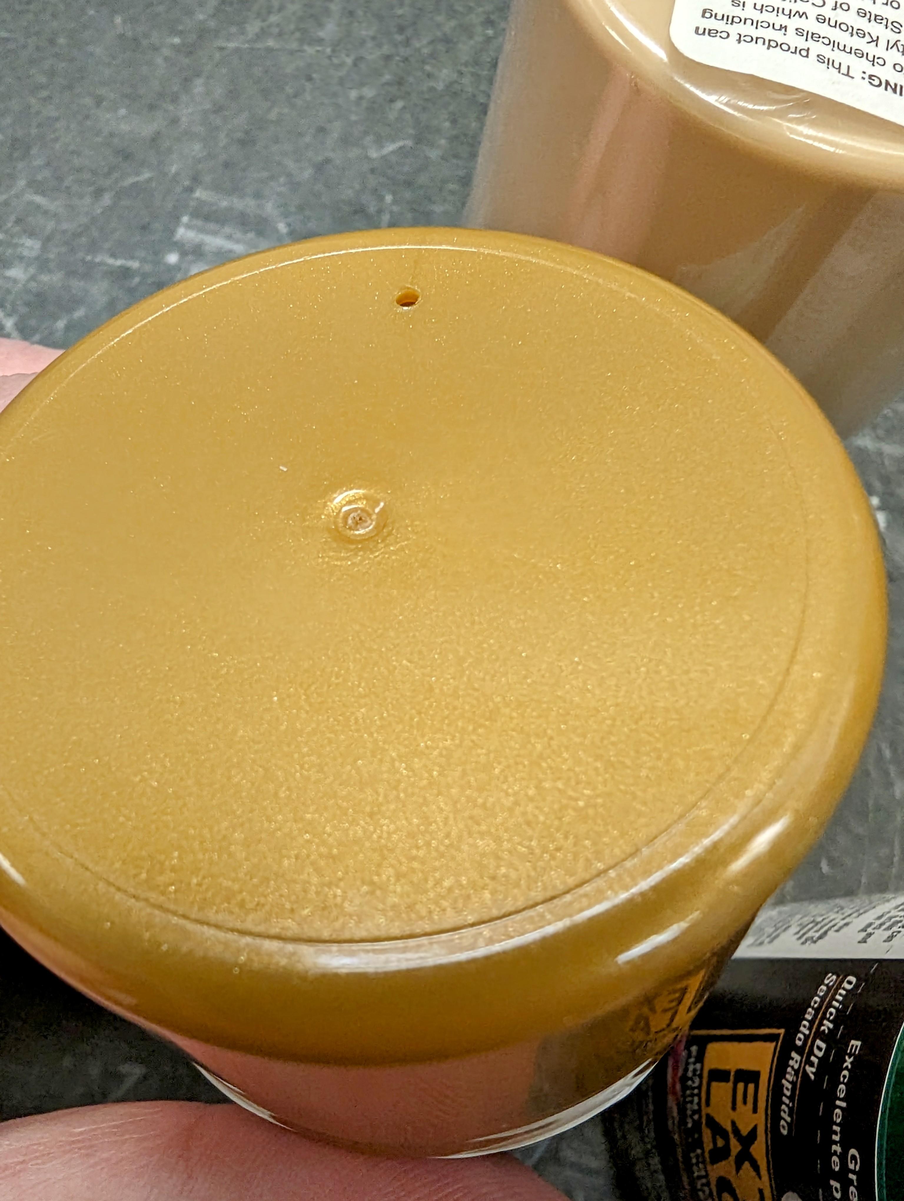
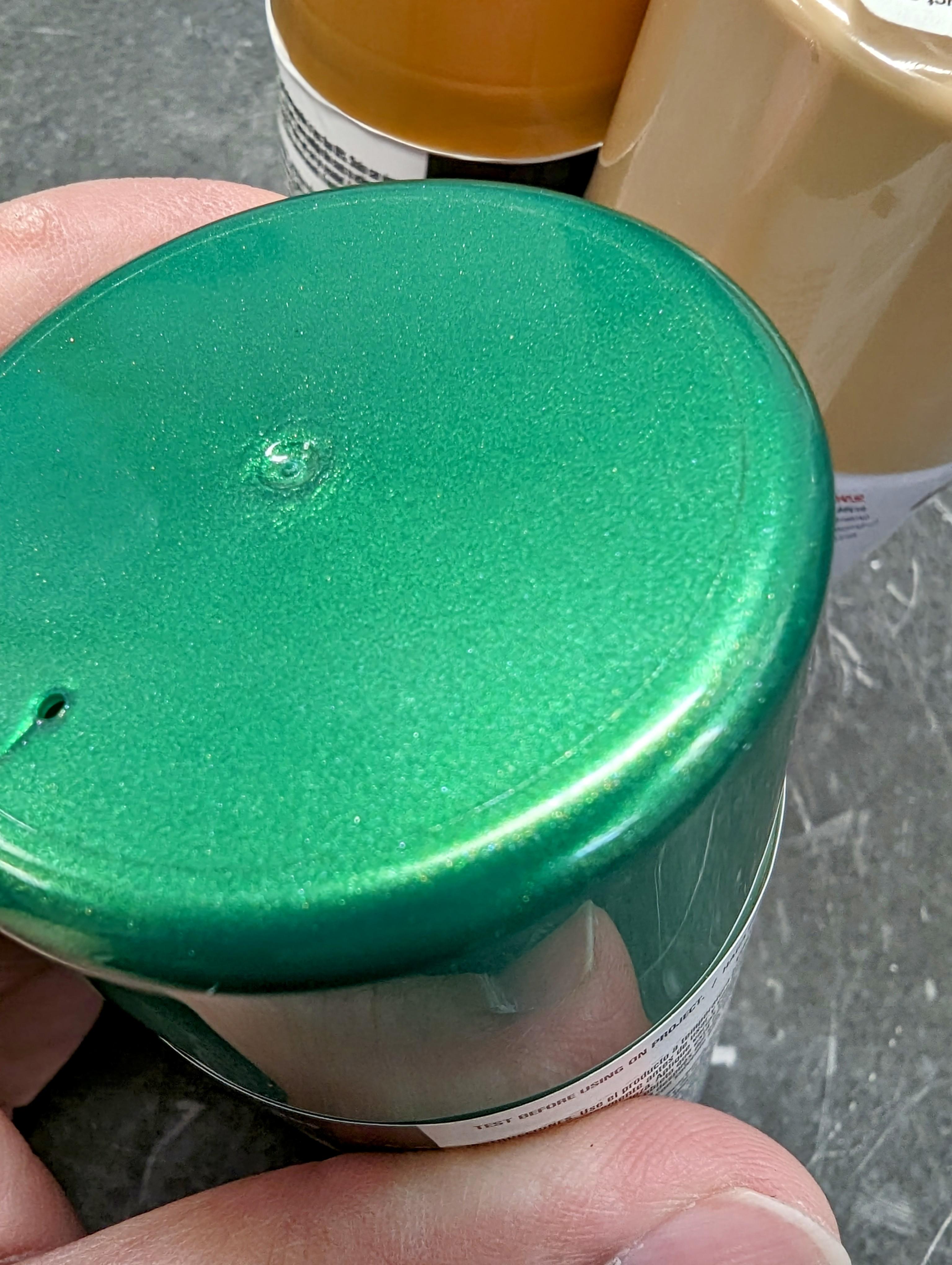
Finally getting a chance to sit down at my airbrush booth again today. After I'd decanted the green and gold to bottles I'd decided that the green was a little too blue for what I was wanting. The original plan was to lay down the green over a gold base coat but I didn't think it'd give me the color I was looking for. So, I ended up mixing them finally settling on 3 parts green to 2 parts gold. Definitely an interesting color that shifts quite a bit dependent on indirect or direct lighting. Gotta knock out the remainder of the non-body pieces and hopefully will get the body painted later tonight.

-
I'll have to check the windshield in mine. I didn't notice anything out of the ordinary with it tho upon initial glance. I've been insanely busy with work and roller derby things and haven't had a chance to sit down at my bench much lately.
-

The Official 3D Printing Discussion Thread
LOBBS replied to iamsuperdan's topic in General Automotive Talk (Trucks and Cars)
I recently found out that the library near my work has a very nice 3D scanner that you can reserve time on by the hour with a library card. I live on the other side of the metro but they still allowed me to get one. I don't know that I have enough need to invest in one just yet but I do have a few projects that having one available will help with. -
This is fantastic work! I really need to learn Blender for a few projects. I feel pretty proficient with Solidworks because it's what I use for work. But I've never really messed with meshes too much.
-
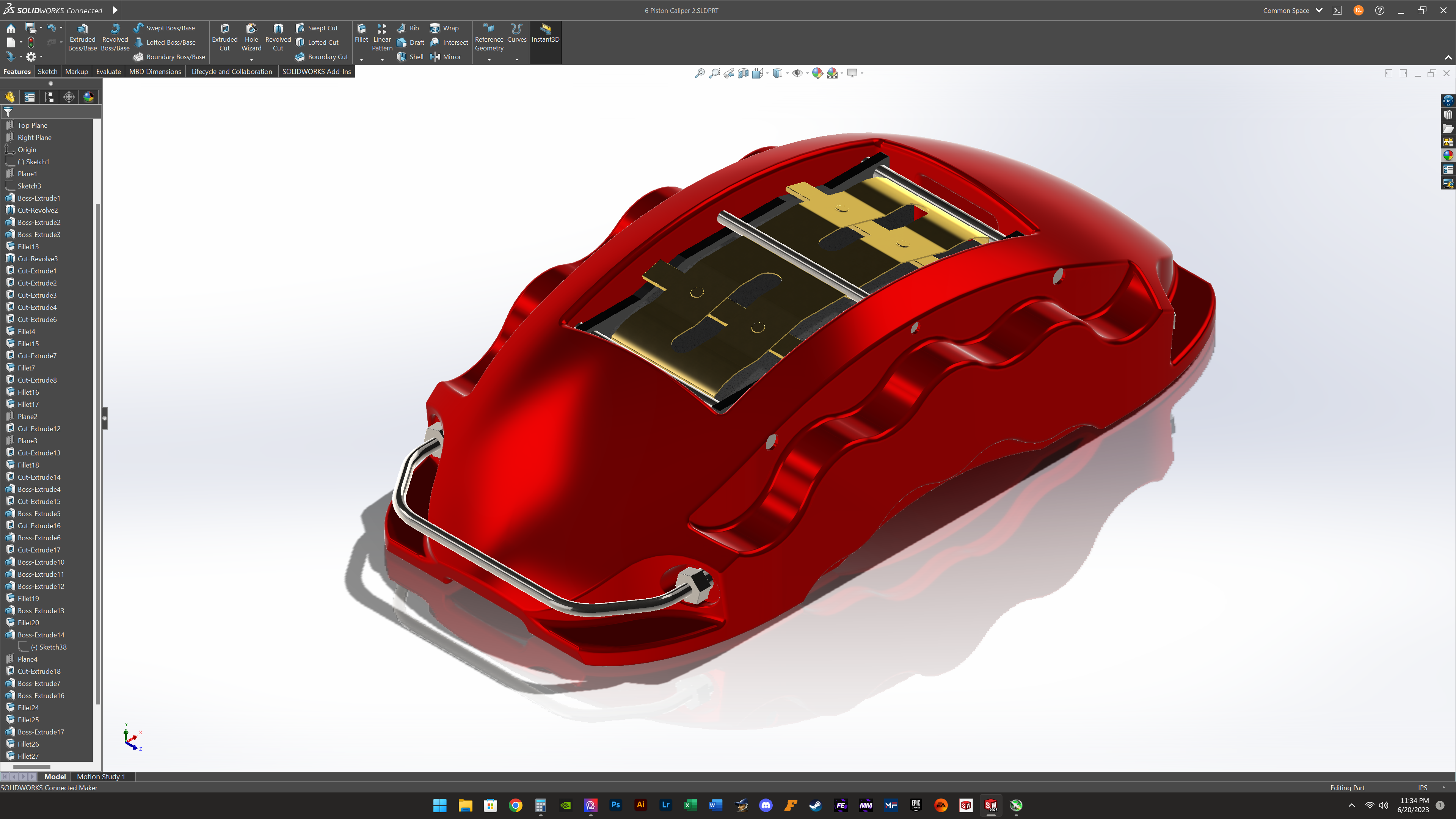
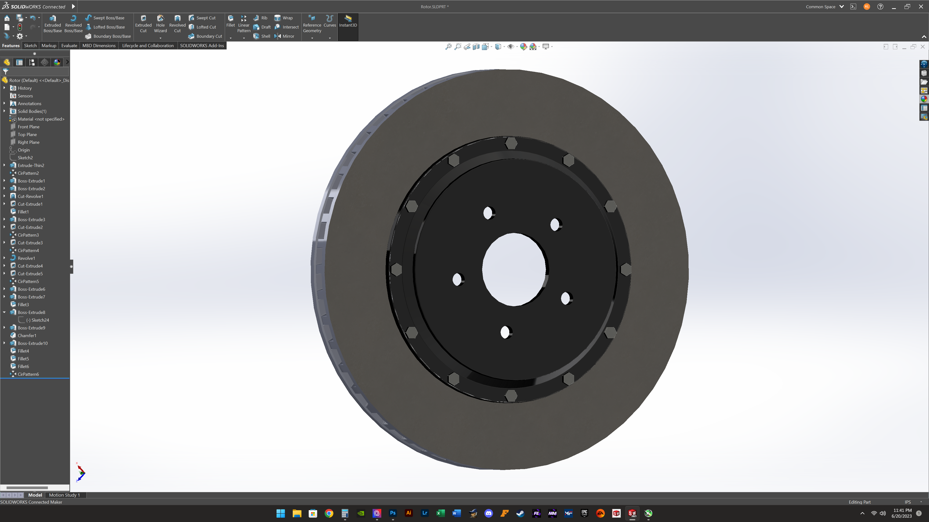
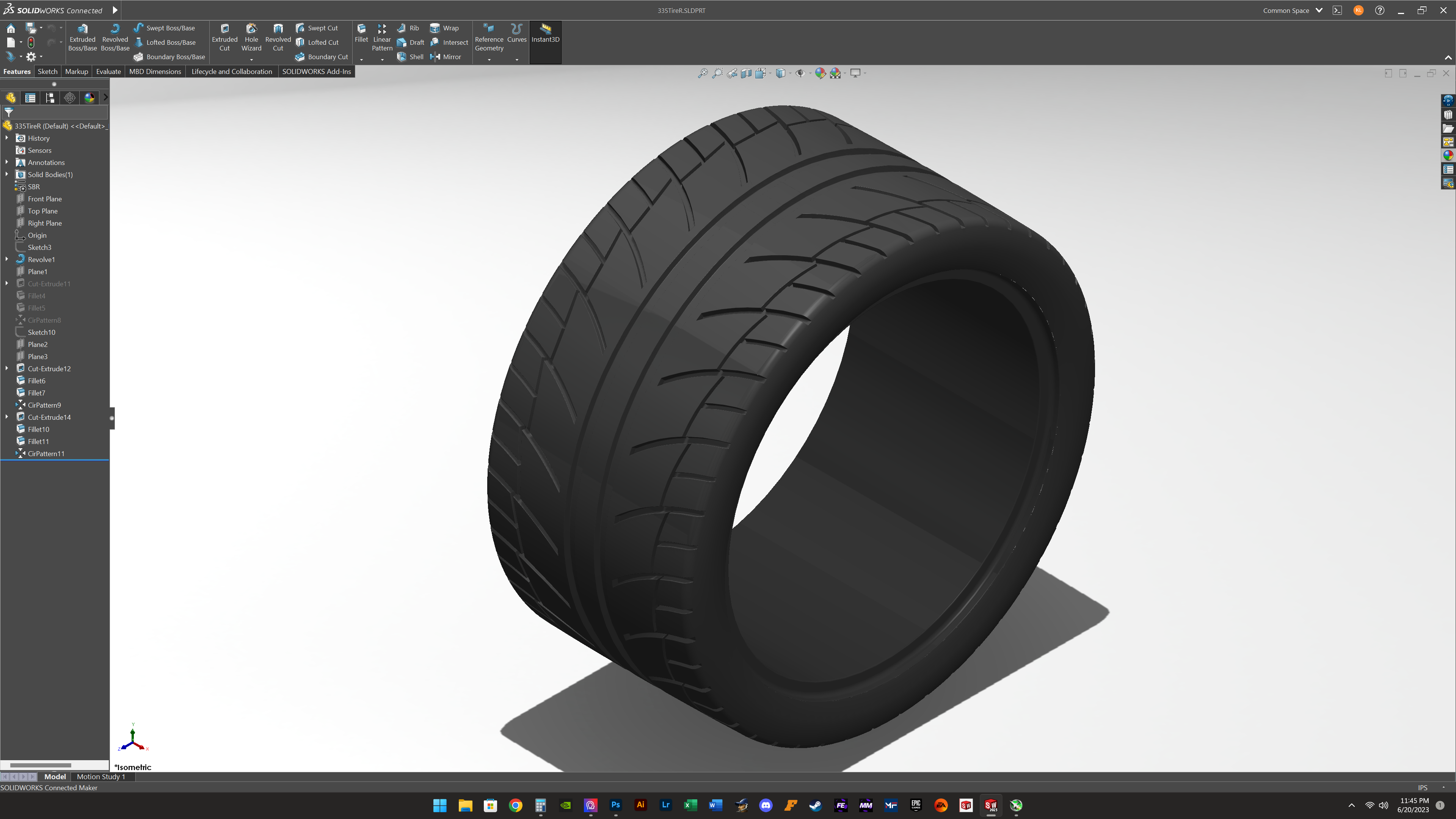
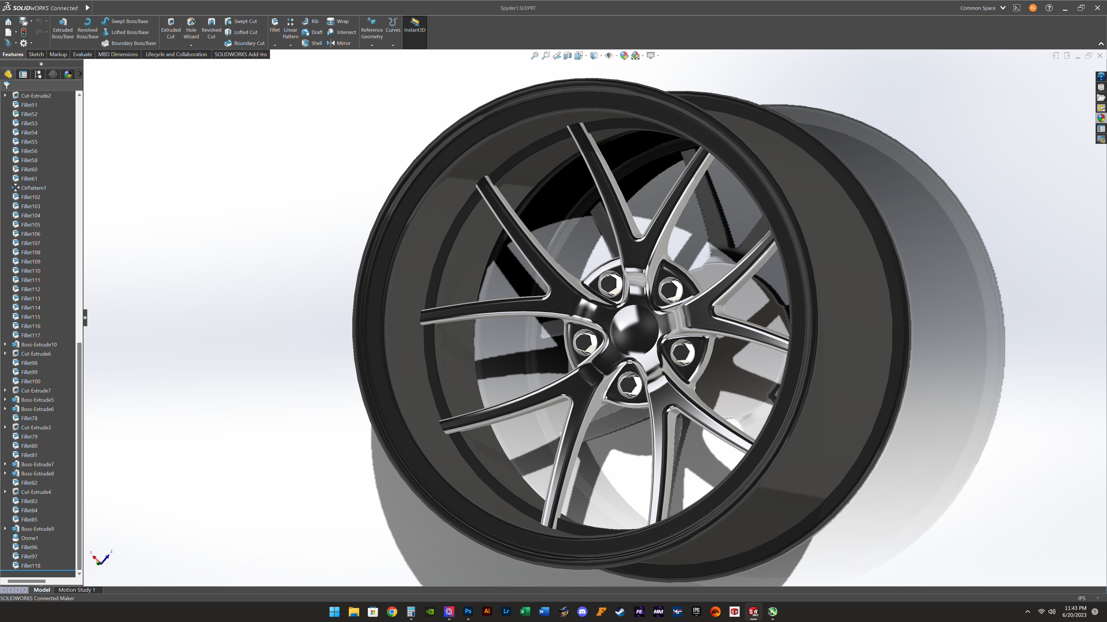
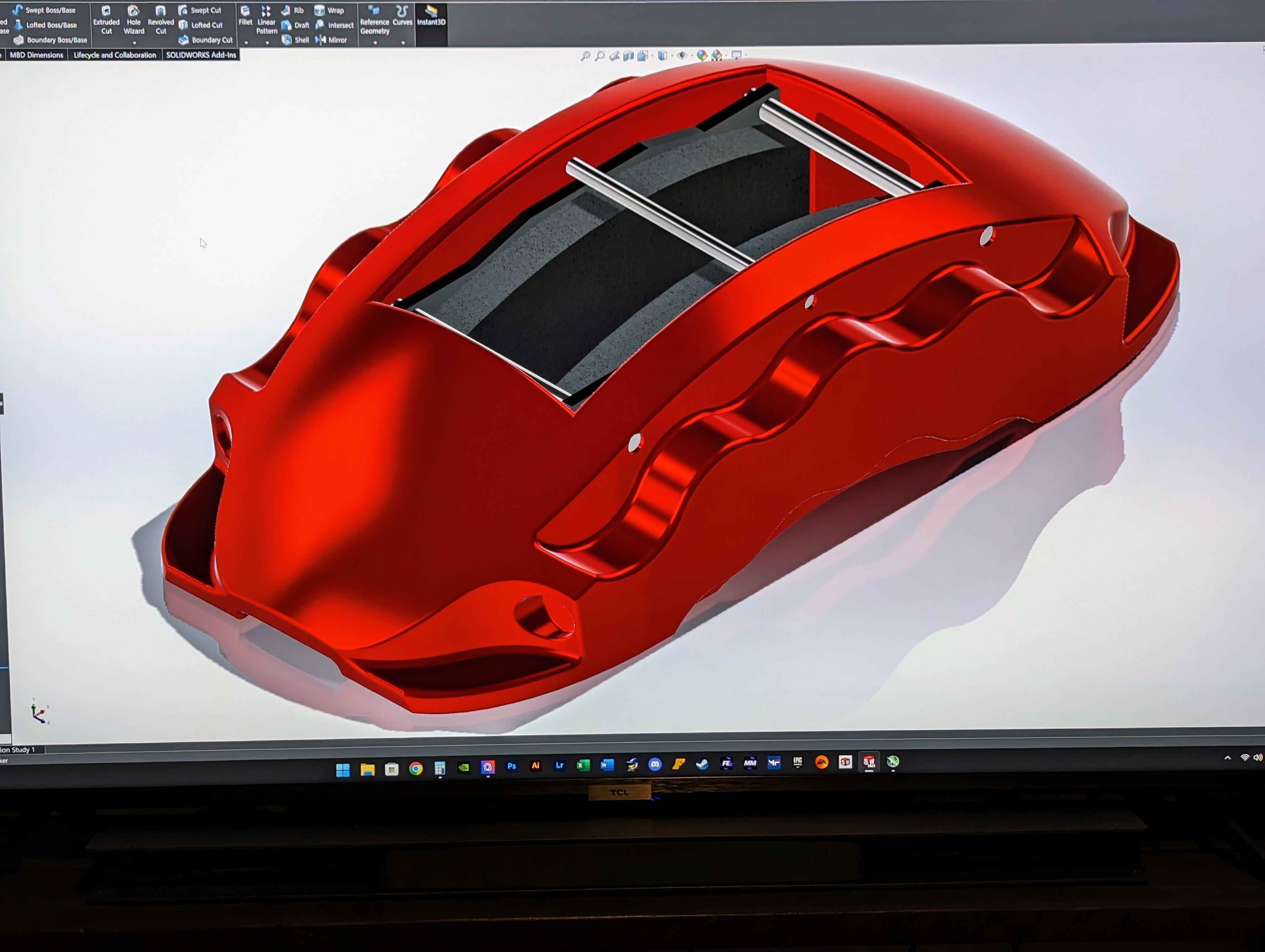
Just starting a post where I can share the parts that I'm working on for various projects. Now that I've picked up a 3D printer I can start to pull some of my stalled projects out of the mothballs and begin to hopefully put them up on the display shelf. 6 piston calipers. Inspired by the Baer 6S but modified to allow for swapping of the pads from the top without removing the caliper. Will be used extensively for my pro-touring projects 15" rotor for 6 piston calipers. The hat for this particular version is spec'd off the C7 Vette. The plan for my '69 Corvette is to design a Roadster Shop style chassis using C7 suspension. Will adjust the offsets of the hats as necessary by project. 295/335 Tires (335 shown). Some version will be used with most of my pro-touring projects. May do other widths as needed. Spyder wheels for my '69 Corvette. 10.5" front/12" rear (rear shown)
-
- 2
-

-
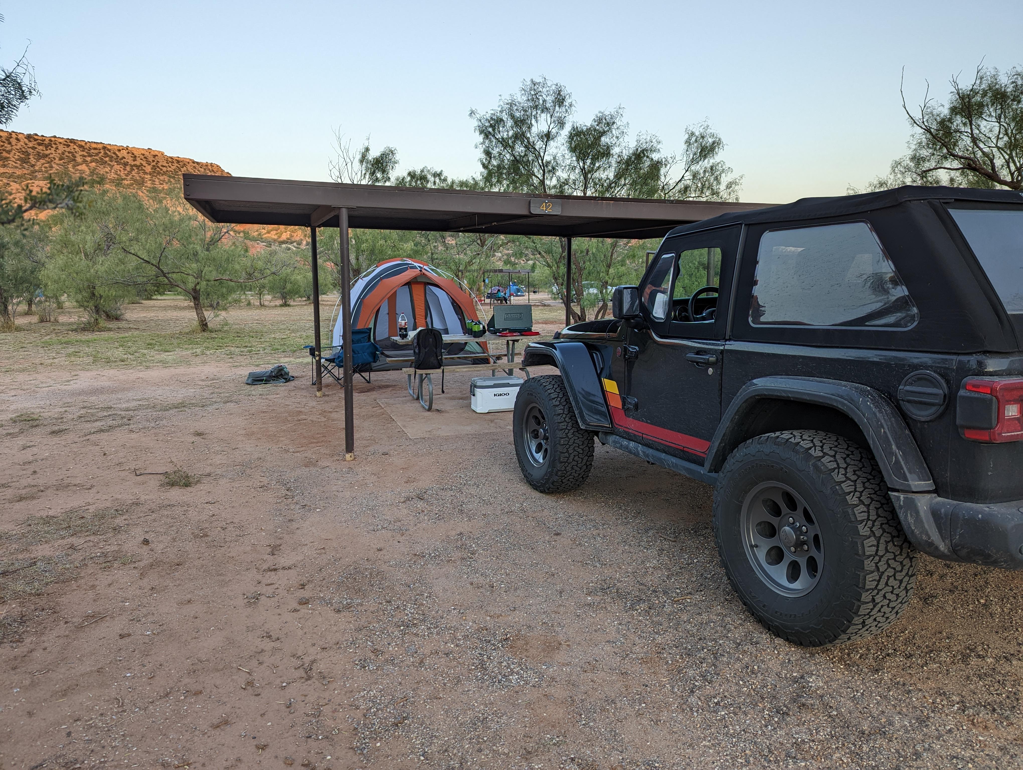
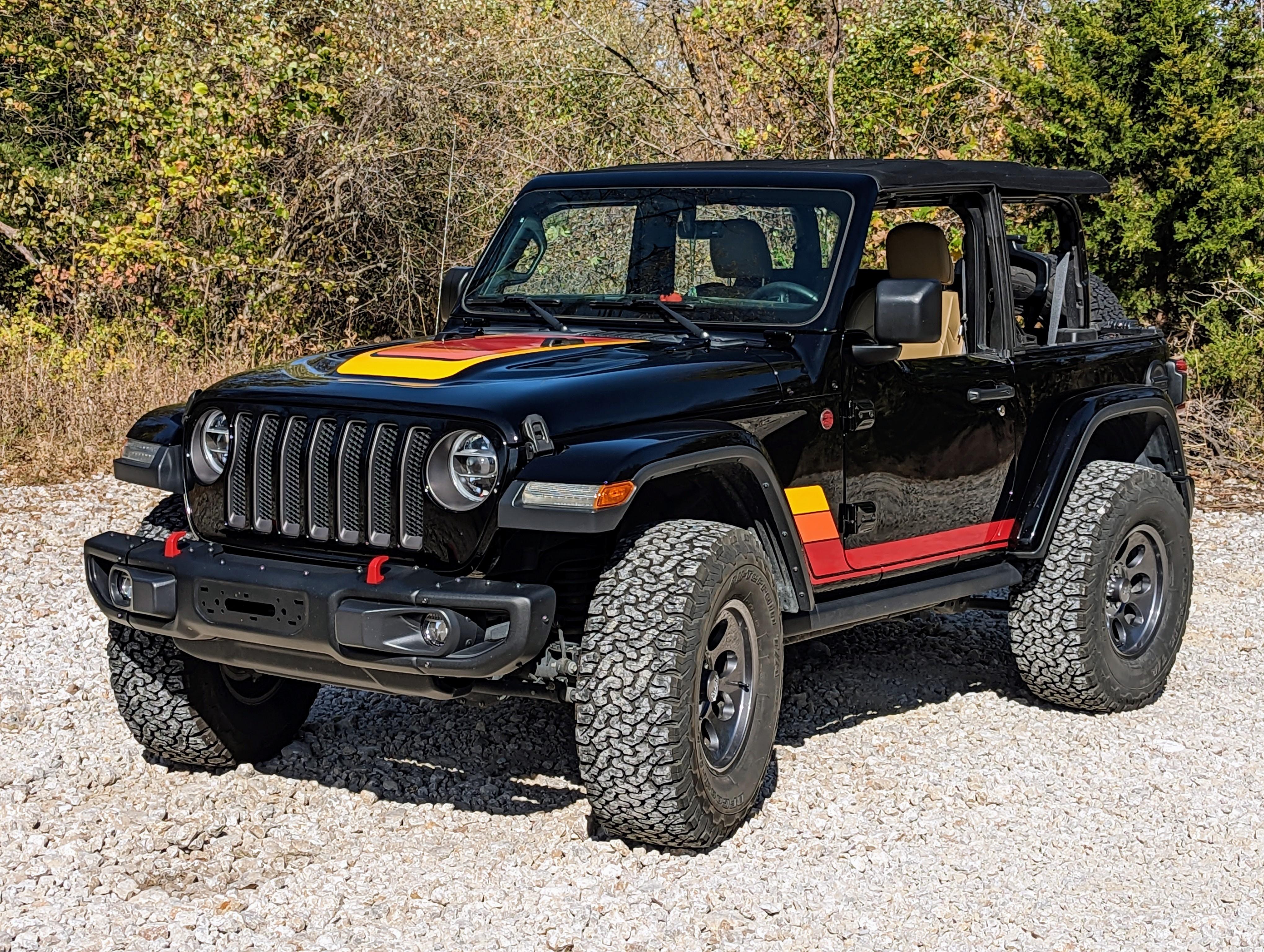
My daily driver JL Rubicon. Wanted a retro vibe so I drew up some stripes in Illustrator loosely based on the '83-84 CJ Renegades and sent those off to a vinyl shop to be cut. Added some 35s on modern "soft 8" wheels. Factory half doors and a soft top were must haves as well. My full doors and hardtop have not been back on even thru the winter.
-
The Official 3D Printing Discussion Thread
LOBBS replied to iamsuperdan's topic in General Automotive Talk (Trucks and Cars)
Just one of several parts that I've been drawing up lately. Just need to add the brake line fittings and draw up the banjo spring that attaches to those pins to keep tension on the pads. I've always liked the looks of the Baer 6S calipers but I prefer calipers like the Brembos that I had on my Camaro where you can change the pads by pulling them out the top without removing the caliper. So, I created my own. 3D printing at home piqued my interest in the hobby again after being away for a few years. I have several projects that I'd shelved over the years because I'd just run out of ways to get where I wanted with it without CAD. Hopefully, I can pull a few of them back down and finish them. I work with Solidworks at my day job and picked up a hobbyist license for home. I bought a Anycubic M3 Premium about a month ago and haven't been able to set it up because I'm still waiting on part of my order. ?
-
I used to stress about missing parts, not having projects done for an upcoming show, etc. but I've calmed down some in my older age?. This week has been hectic and I realized pretty quick that I wasn't likely to have this done for Heartland this weekend. My roller derby league decided that they want to use my Jeep again in a parade tomorrow so I had to take a night to detail it. And we've had a few tough scrimmages this week now that we're into co-ed season. I did receive the axle from Modlbldr last night and it's in the Castrol Super Clean being stripped of its chrome. But with the pressure of having it done for the show off I have decided to go ahead and kitbash / add some detail. I picked up a '32 Ford 5W that I'll for sure be stealing the brake booster/master cylinder out of and probably the '40 Ford taillights. I may nab the 392 as well and slap a set of lake headers and an Hilborn style intake on. It's either that or keep it Ford powered by printing a Coyote or 427 SOHC. I love my LS/LT engines for pro-touring projects but yet another SBC in a '32 Ford just wasn't feeling right. Anyhow, I'll try and get some in progress pics taken and posted up soon.
-
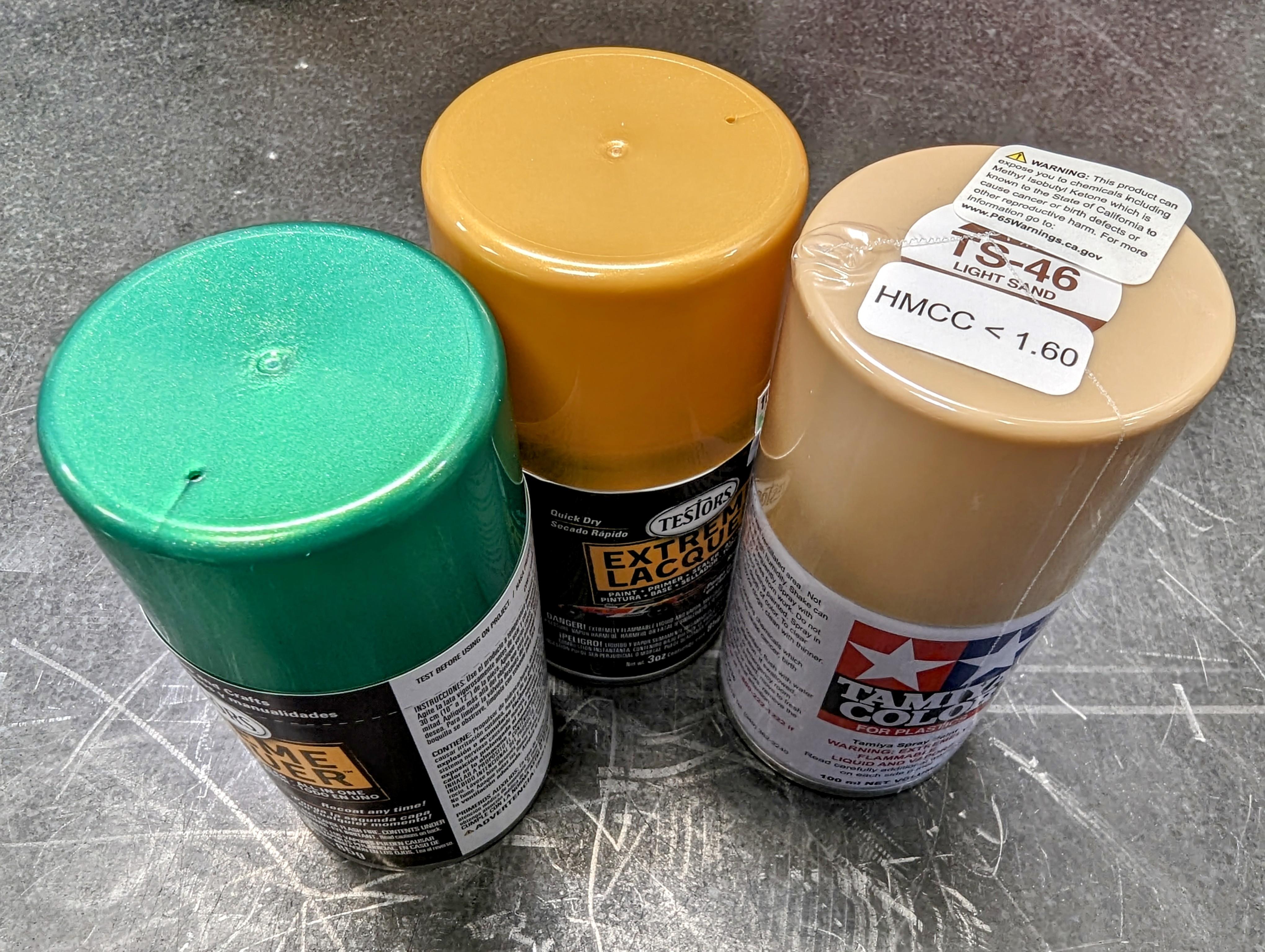
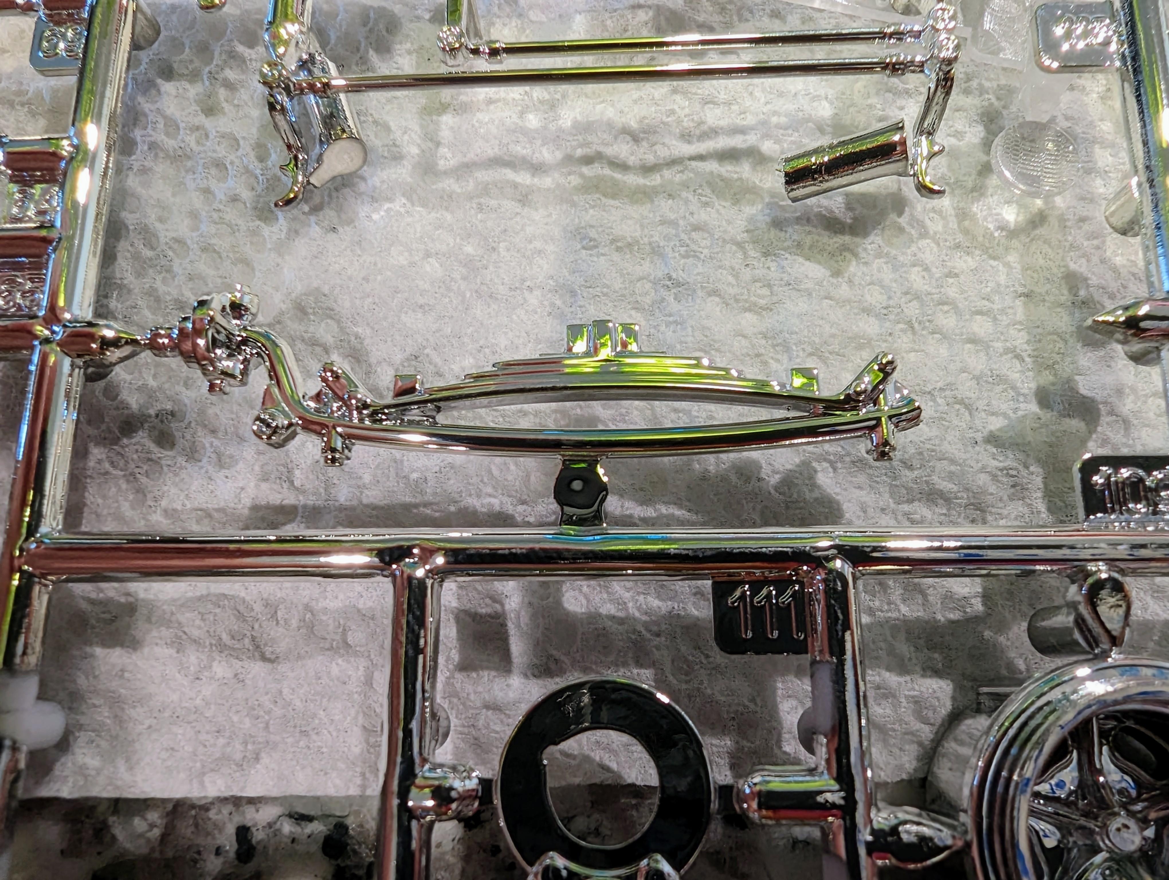
Color scheme will be this Testors Mystic Emerald which appears to have a very fine gold metallic in it. I'll attempt to draw that out a bit more by laying down a base coat of Testors Pure Gold first. For the interior I'm going with Tamiya Light Sand which I'll also lay down over the Pure Gold in hopes of adding a little warmth to the color. I did also strip all the kit's chrome with Castrol Super Clean and will be shooting those pieces with various tones of Alclad and Molotow where appropriate. Hopefully, this weekend's painting is productive and I can have this week to get it all assembled and detailed for Heartland next weekend.
-
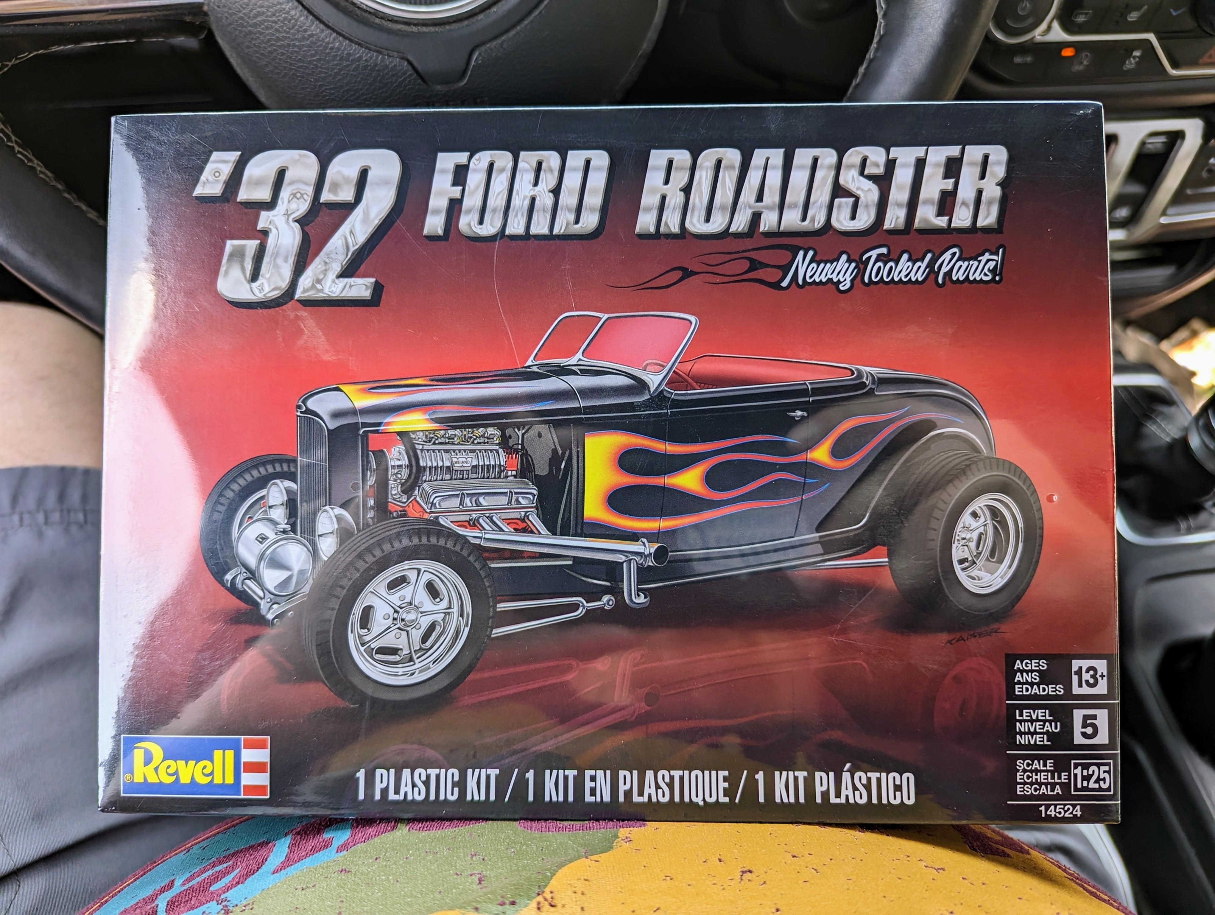
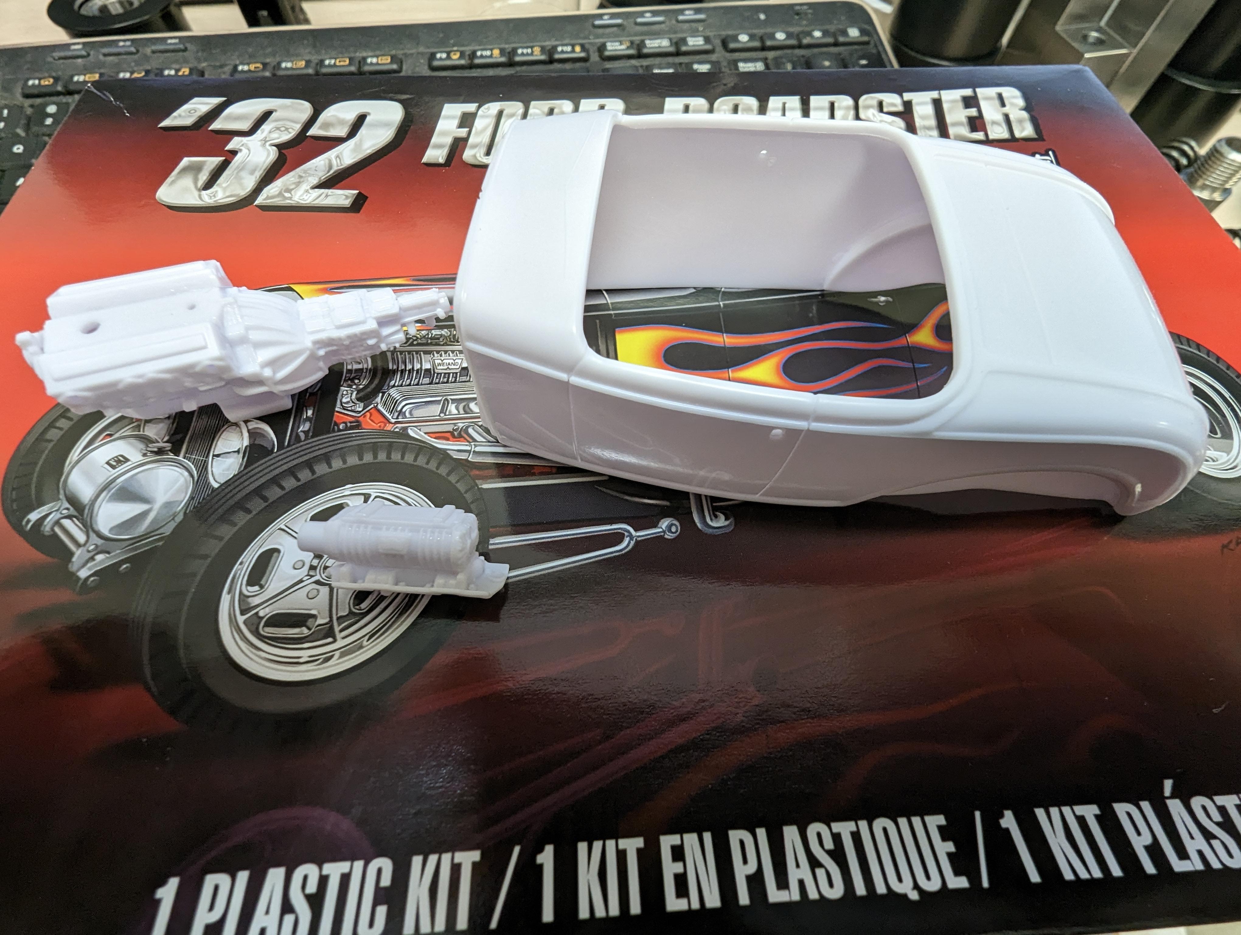
This will be a pretty much an out of the box build for me which I haven't really done since I was maybe 12 years old. I've been away from the hobby for a few years and was looking for a project to get my skills sharpened back up a bit. The Heartland Nationals in KC is next weekend so I set that as an artificial "deadline" to get it completed. My normal genre is pro-touring builds but with the short timeframe I chose to step outside of that comfort zone and pick a subject that I wouldn't be tempted to kitbash, super detail, etc. The new tool '32 Ford, revised Rat Roaster, fits that bill nicely in that it's custom enough to take that edge off. The first snag I hit tho was that the front axle was a short shot. One of the hubs and about a quarter of the axle total was missing. Thanks to Modlbldr, I should have a replacement in time to make the show. I spent a good chunk of my spare time this week doing all the prerequisite parting line/seam cleanup and as much pre-assembly of like colored parts as possible so that this weekend I could park myself in front of my airbrush booth and hammer thru the painting.
-
3D Printing Storefront Directory
LOBBS replied to Mr. Metallic's topic in Car Aftermarket / Resin / 3D Printed
Same. I just bought an Anycubic M3 Premium a few weeks ago. I've purchased a few files already and followed a couple of accounts from Cults3D. I've got years of experience with Solidworks as well so I've been busy drawing up my own parts to jump start several shelved projects as I try and get back into the hobby. -
2019 GMC Sierra ( UGLY Truck)
LOBBS replied to ranma's topic in General Automotive Talk (Trucks and Cars)
The '19 Silverado is just awful and don't even get me started on how they ruined the Camaro for '19. That being said, the GMC is the much better looking twin and has been now for a few generations. -
Gorgeous
-
Corvette Grand Sport C7 - July 31 - final stretch update
LOBBS replied to RestoModGuy's topic in WIP: Model Cars
Excellent work on the conversions necessary to bring the body up to Grand Sport/Z06 spec. Also thanks for the heads up on Plamoz. Several things in their inventory that I need for various Vette projects -
Nothing like a slump buster to get back into the groove of things.
-
That's a cool color!
-
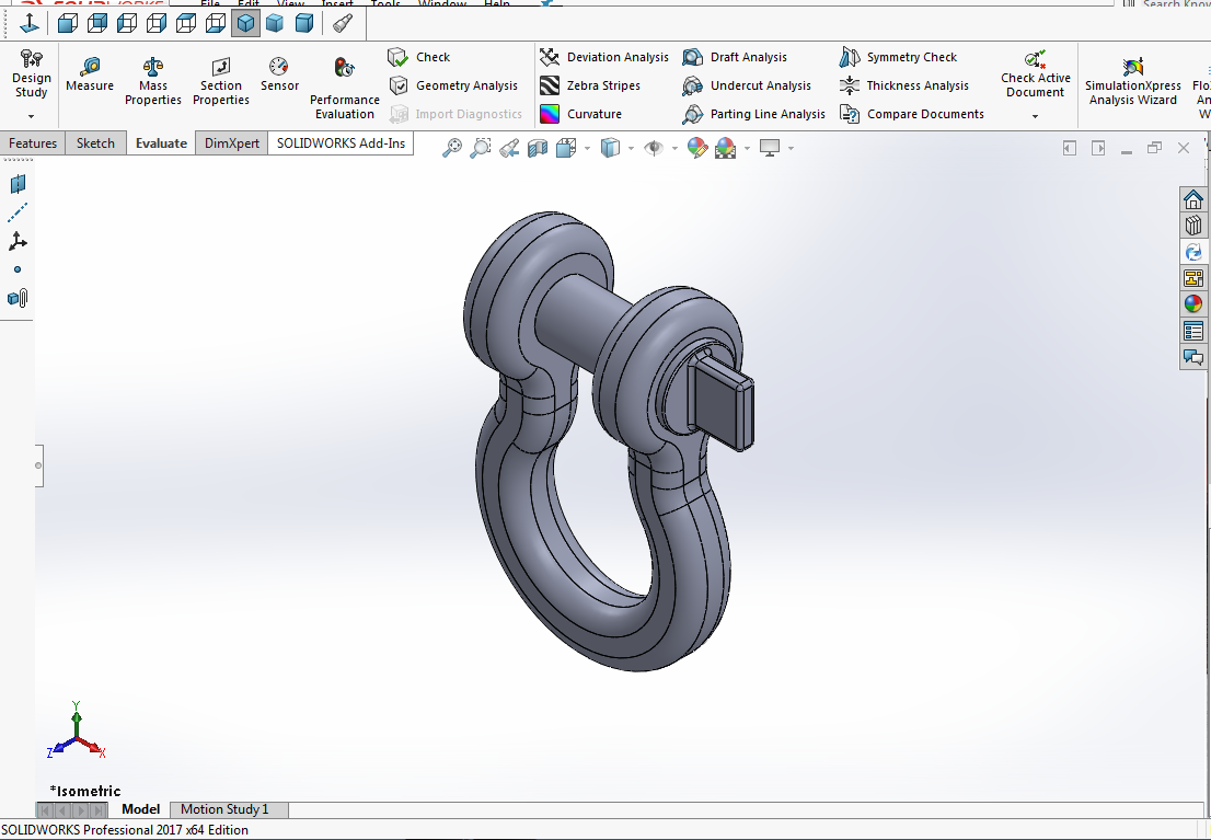
No more CAD pics after this, I promise. I found some additional info and tweaked my original designs. I made the distance between the ears of the shackles wider, completely redrew the shackle anchor to make the base 4" x 3" (this seemed to be more in line with several of the 1:1 bolt-on kits) and while in the course of doing some research on tow hooks for the winch I ran across several articles that pointed out the superiority of using a safety thimble and shackle versus a traditional clevis hook so I went that route instead. I don't have a huge interest in off-roading with the exception of a soft spot for Jeeps so a lot of this was plain old eyeball engineering.
-
Ohh, love early Trans Am. Coming along nicely.
-
And the shackle's matching anchor.
-
Tow shackles drawn up
-
This is printed in the white versus the frosted ultra detailed correct?
-
Finished up the CAD for the light bar.
-
Wow. Excellent build
-
Excellent work