Bill Eh?
-
Posts
1,250 -
Joined
-
Last visited
Content Type
Profiles
Forums
Events
Gallery
Everything posted by Bill Eh?
-
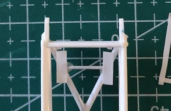
Replacement Wishbone attachment brace glued to the bottom of the crossmember.

-
I glued the rectangular moon tank supports onto the frame cross member. Since the gluing surface was not large, I will let these set up for a while, before I attempt to cut off the joining rod. I used regular Tamiya cement applied with a toothpick. The second shot is just a comparison with the kit part. Question for you guys. Am I doing too many updates with too little progress? I'm new to this WIP thread process.
-
I jump around a lot on this build. I looked at the engine components and decided to open up the air intakes on the fuel injection unit. I used a drill bit to find the size of the molded opening, which was about 1.1 mm. I then increased the size up to just under 2.2 mm. At that point, I decided not to press my luck by going any larger. That would normally have been what I would do, and result in another kit going to the shelf of doom. Although not a true scale wall thickness, I think it looks a lot better. The best non-styrene option would have been to use either brass or aluminum tube. Engineering that would have been way beyond my skill set!
-
Thanks Jim. I won't throw away the Vallejo putty, as you said it has its uses. Hopefully I will be a little wiser in my choice of putty use.
-
I can see a lot of discussions taking place, behind closed doors re the stewardship of races in the coming season. LOL
-
Jim, I agree with you. But the stewards did the same kind of tweaking of the rules when Hamilton's Mercedes had all four tires leave the track at turn 6 of lap 1. Was he required to give the place back, as normally would be the case? No, creative interpretation,
-
Thanks Peter. After sanding down all of the body seams, I was disappointed with the results of the Vallejo putty. I redid all of them with Tamiya putty along with the moon tank. Both halves of the moon tank slightly taper from the outer portion to the centre where they join. This gives a valley-like appearance around the centre of the tank. LOL
-
You question the fairness of Latifi crashing, or the fact that a Safetry Car was deployed to cleanup the debris? LOL
-
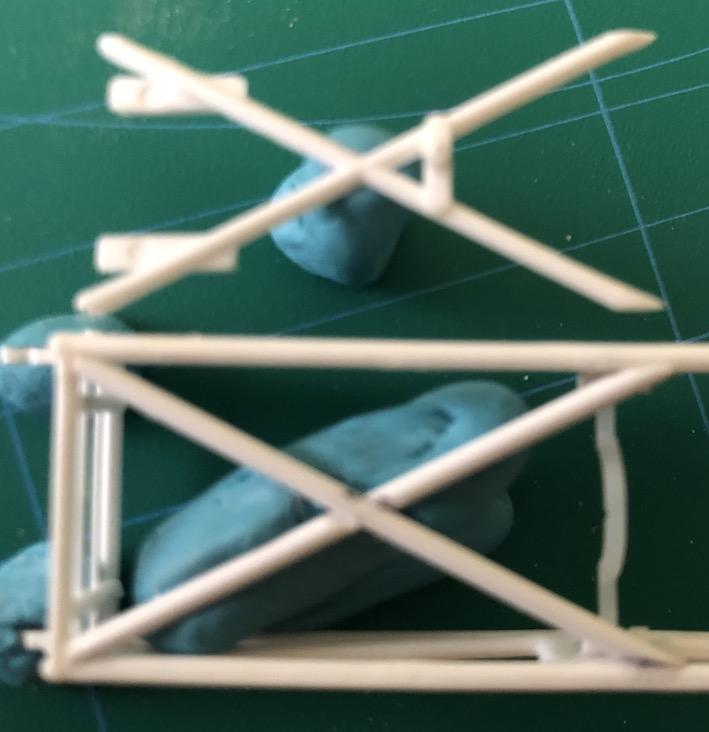
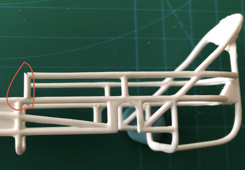
This picture shows the distance between the legs of the moontank compared to the original part rectangular supports they are supposed to rest on. The legs would overhang on both sides. This was one of the reasons I decided to make a replacement cross member.
-
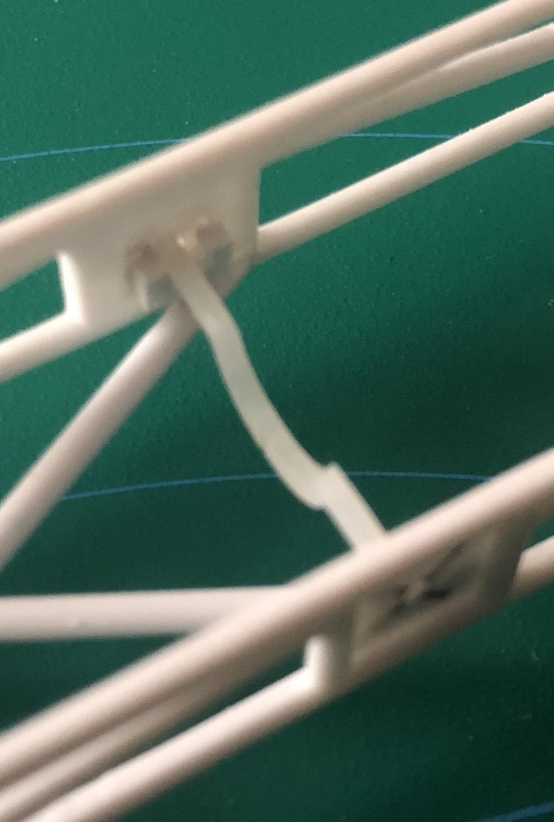
When I last left off, I was stumped as to how I was going to handle a portion of the build. As previously indicated, I decided to replace the cross member which sits in the lower front portion of the frame. I went ahead and made and installed the replacement cross member. However, I did not give much thought as to how I was going to add the rectangular supports (sit on top of cross member), nor the wishbone attachment brace (sits on bottom of cross member). When predicaments like this come up, my progress tends to shut down. My main concern was how to attach both supports so that they were both parallel to each other and also level. I came up with what I hope will be a workable solution. From my measurements of the original piece, I made the two rectangular supports from styrene strip (0.75 mm x 2.5 mm x 9mm). I then glued them together with thin piece of styrene rod (10 mm long). However, when I looked at the spacing compared to the legs on the moon tank, I was not happy. So I remade them and reduced the space between them to 9mm. The wishbone attachment was far more straightforward to recreate. I'm really slow at this sort of thing, and it has taken me over 3 hours just to get this done. On another note, I was trying Vallejo Plastic Putty to fill/smooth the joints of the body panels. Never again. It would not sand well, nor leave a feathered edge. It just flaked off. This was after letting it cure for over five days! Back to tried and true Tamiya Putty.
-
That's what I'm hoping for Dennis. The best laid plans and all that... LOL
-
In a reference photo, I noticed the split in the body right at the level of the opening for the Pitman Arm. I will rescribe this as well as the opposite side. I hope this gives a better appearance than just gluing the top body panel in place with side panels already glued to the frame. Time will tell.
-
Thanks Carl Jim, seeing your post motivated me to do the same! Thanks. Mooneyes vs. Mooneyes, wouldn't that be a sight! LOL
-
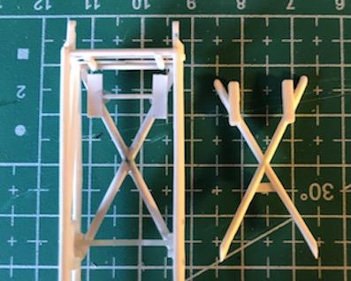
I was not happy with the fit of the cross member, which glues in at the front of the frame. I made a new one. It still requires the rectangular pieces to be placed on the top for holding the moon tank, as well as the downward facing pin to attach the back of the wishbone. I learned that it takes a great deal of patience to fish-mouth 1/16" rod. The picture shows the new cross member glued in place, with the kit part right beside it. Please excuse the blue tac. More to come....
-
The engine mount, as indicated in the instructions, is far too wide for the frame. To make it fit required cutting off the "triangular" portions on both sides of the engine mount. This meant that the gluing surface on the engine mount was next to nothing. I made c-hannel style mounts, and glued them facing up on both sides of the inside of the frame. With the firewall glued in place, there was interference with a vertical portion of the frame. To eliminate this, I moved the vertical portion of the frame, slightly rearward on both sides. This solved the interference issue. The joints need some work. LOL
-
By building up all the body panels, I had to think of a work around to installing the rear axle. My solution was to refabricate the rear axle into a component assembly. I started by installing a new styrene tube through the quick change differential. The width of this tube was cut to match the exact width of the frame when installed. This way, the one piece body can slide onto the frame from the front. The outer portions of the original axle were cut off, and refabricated with various sizes of Evergreen tube, rod, and strip. These new axle end, with wheels attached, will just slide into the axle/quick change already mounted in the body.
-
I purchased this kit a couple of weeks ago. I have been in a non-building slump for too long. This is the kit that got me building again. Work started with assembling the frame. I glued the attachment points, moving from rearmost to the front. All in all, the frame members lined up well on the two halves. Please excuse the putty, which is yet to be sanded. After watching HPI Guy's build up on YouTube, I really wanted to do something about the seams/gaps between the panel components. So, I decided to assemble all of the pieces and putty the seems. Again, this needs sanding. There are two slots on either side of the firewall where vertical portions of the frame show through. Again, this did not appeal to me so I tried filling these slots in with strip styrene, to get a solid firewall appearance. Looking at it now, I will more than likely remove this piece and create a solid new piece from sheet styrene.
-
Jim, I am working on my kit too. Maybe I should start a thread. LOL The motor mount bracket part, as indicated in the instructions, is far too wide to fit between the frame rails. In fact I had to remove the triangular portions on both ends of the motor mount. This meant that I had to create new attachment point/supports for the motor mount. I made c-channel style supports, and glued them to the inside surface of the square plate sections of the frame. I hope you don't mind me interjecting this way.
-
Jim, I believe you have installed the front cross member in the frame upside-down. The two rectangular sections, should face up, as I think they were intended as the moon tank supports. Just rear of the cross member centre, you have the pin facing up. I think it should face down, as this is where the wishbone attaches.
-
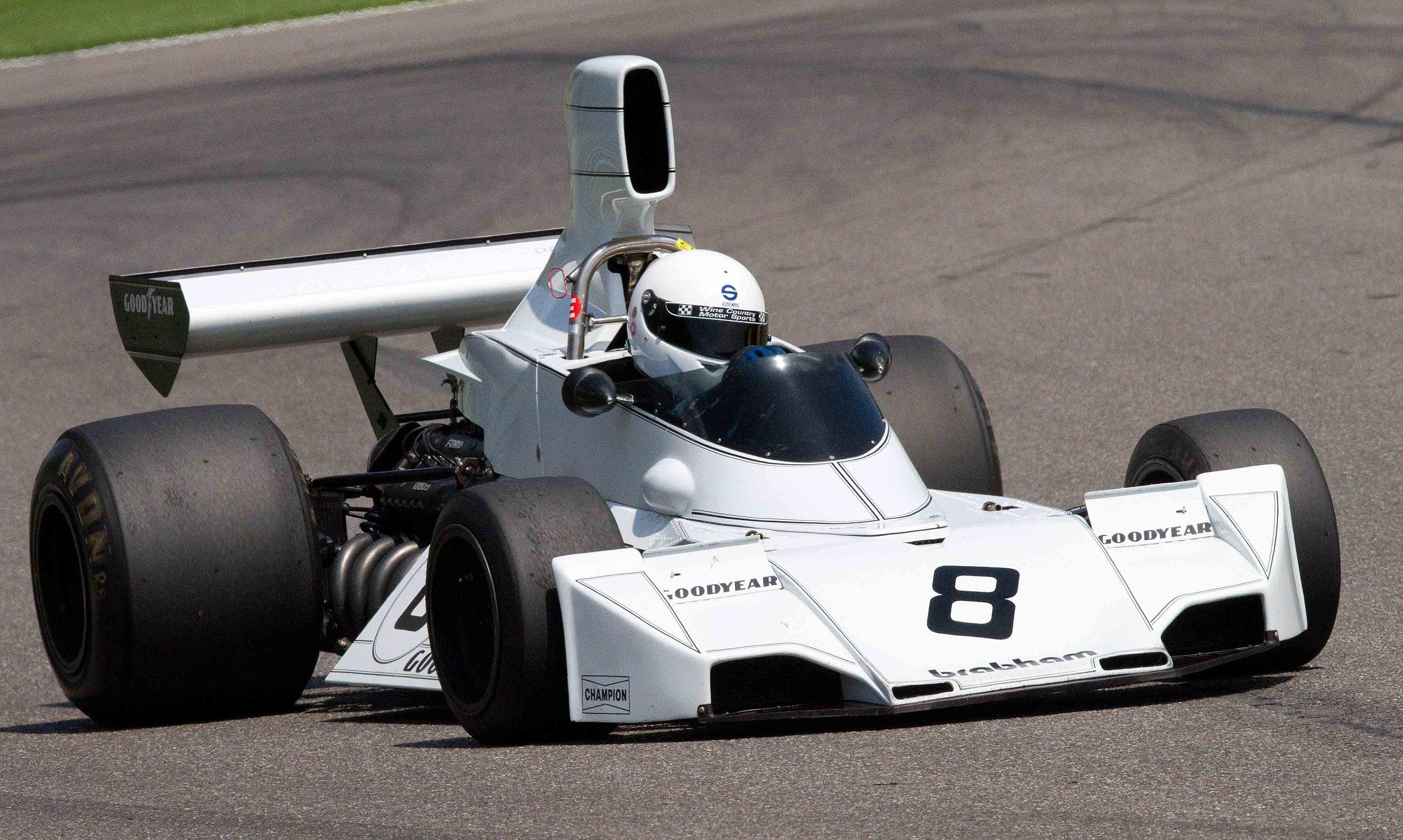
 My favourite car of that era was the Brabham BT-44
-
Hi Jim. So the Hansa 281 operates in the same manner as a trigger style airbrush, but using a conventional lever instead? I recognize the needle packing screwdriver, but I am curious about the tool just to its right. Is that a nozzle wrench of sorts? I've thought about purchasing the ring for converting to a minimum capacity bowl, but not bought one yet. All ai all, some excellent purchases, especially that Hansa 281 model!
-
It is true that FIA stated that safety was the motivation. They have to provide a plausible reason for the ban after all. However, the banning of the airboxes was simply a means of the FIA clamping down on the "ram-air" effect they created in an effort to reduce engine performance. The bigger the opening, the more air - and thus, intake pressure - you had going to the engine. The higher you had the intake, the better chance you had of capturing cleaner and cooler air. Engines prefer cooler air. So, the FIA came up with new rules stating a maximum height for all bodywork and just like that, put the kibosh on the tall intakes. Not much different from the 1994 season, when the FIA demanded holes be cut in the airboxes to reduce performance after Senna's death.
-
I believe that this was done in an attempt to reduce speeds by reducing the amount of air getting to the engine. Did it work? No. As Lee has shown with the pictures of Ferrari's adaptation in the 312T to the 312T2. No tall airbox, but clever thinking still got the same volume of air to the engine. The McLaren M23 also went from a tall airbox to a design where the air intake snorkles protruded horizontally behind the driver's head. James Hunt, won the '76 Championship with his revised McLaren M23. My first attendance at G.P.s happened that year. I went to the Canadian G.P. at Mosport and the United States G.P. at Watkins Glen. Both races were late in the season, and the low air boxes were in use at that point. The Lotus 78 adopted the same design feature that McLaren used, with the horizontal snorkles behind the drivers head.
-
This is contrary to what I have found out. It is called Mr. Rapid Thinner, because as you said, it flashes out faster than Mr.Color Thinner. Because of this, it does not allow the metallic particles to level out uniformly, but rather maintain the randomness that they achieve when sprayed on a surface. The reason for this is to better replicate the metallic that is being sprayed. As for a chrome surface, I would think that you do want to achieve a more uniform result, and would best achieve this with Mr. Leveling Thinner.
-
Jim, as with your H & S brushes, these two Iwatas are just over the top in a good way. Me being something of an airbrush hoarder the top picture of your post fascinates me. Please share who makes it and where you purchased it from.