Farmboy
-
Posts
518 -
Joined
-
Last visited
Content Type
Profiles
Forums
Events
Gallery
Everything posted by Farmboy
-
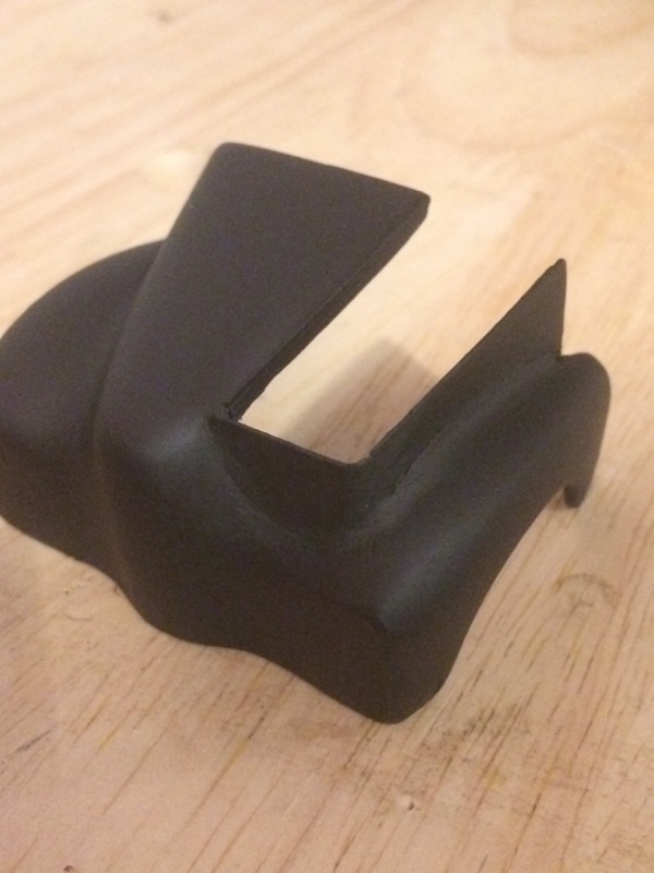
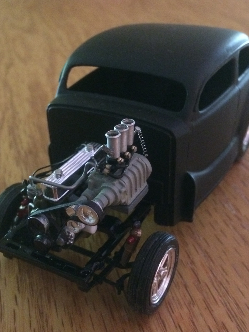
Mark, here are a couple of pics of a decade ago attempt to have a blown 6 cylinder, kind of a combination of belt driven/direct Potvin blower style engine. Pretty simple right down to the sideways carbs. I may upgrade it... as always, comments and observations welcome and Dan, here's where the nose sits. I cut the rectangle to fit the engine and pulley length then added some sheet styrene to build the 'wall'. Bodywork is in the rough stage right now...

-
Dan, I did a bit of surgery to the front end to adapt. I'll post a pic hopefully tonite. Thanx for the kind words everybody.
-
Mark, inspiration started with a recently bought 40's Plymouth kit with an L Head 6 in it. I didn't know much about the engine and ended up on the H,A.M.B. (Jalopy Journal) for info. Browsing around I found photos of sixes with blowers! I dug around that, links, and other sites till I had enough info to put one together. Actually I still have an old 32 Ford kit I built years ago where I've simply glued a blower on the side of the 6 cylinder block and led two aluminum pipes (think of the Orange Crate) to the 'intake' on the other side, I'll take a pic of it and post it here later.
-
Thanx for the comments everybody. Thought I'd give it a try. I've seen potvin setups but not with a sidemount blower. thought it was time to do one.
-
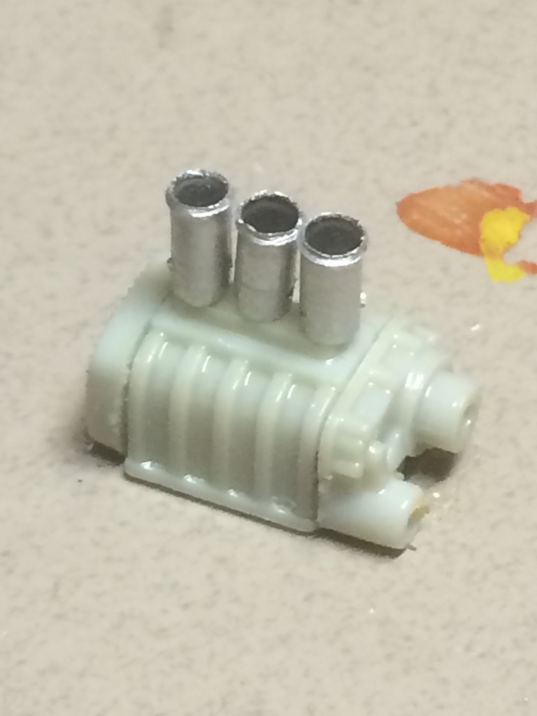
The blower sits on a scratchbuilt intake manifold. I gave it three inlets -- 2 per cylinder --, arranged to give even room for the exhaust manifold pipes I made from a set of v-8 exhausts. each one had a 1/2/1 configuration. I cut them 'mirror' to each other, leaving a 1/2/2/1 configuration and reassembled them. The whole thing fits properly on the engine in the following sequence:. single exhaust - dual intake - dual exhaust - dual intake - dual exhaust - dual intake - single exhaust I will add a single header pipe to the exhaust manifold and end it with a small megaphone in the driver's side wheel well.
-
Here's my rendition of a blown chev 250(ish) straight 6. It took a bit of research but the end result is a believable model. It will go in the front of the Revell Chopped Austin it's sitting in for the mockup. I did use one aftermarket part. It's the throttle return spring on the rear of the blower. I just had it lying around, but the whole engine is a parts box baby with lots of wire, solder, aluminum, homemade belts and bits and pieces. The banjo bolts were made from seed beeds and pin heads. Last thing will be to route the cooling hose on itself from the top out to the bottom in. It's a drag car, no way streetable so no rad required.
-
That finish looks baked on. Xcellent!
-
Went ahead and replaced the too thick ignition wires with a smaller diameter. Looks much better I think. Redid the distributor cap as well out of a piece of yellow sprue. All that remains is the installation of engine pulleys, pulley/tensioner extensions for the blower and a few miscellaneous tidbits the it's on to the body. Comments and observations welcome
-
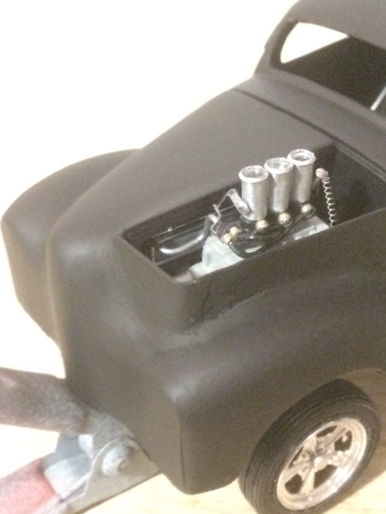
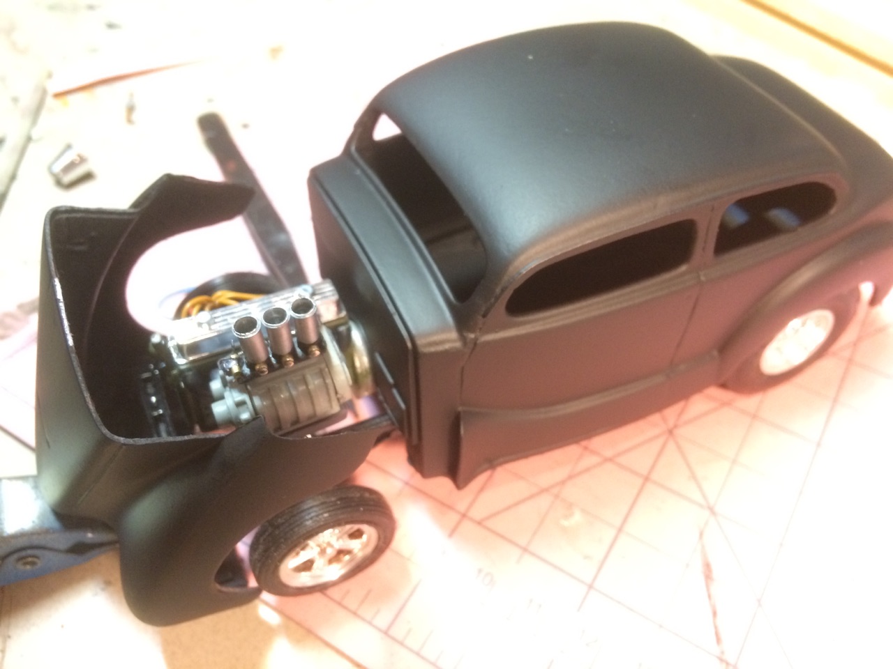
....and the obligatory mock up. Still in primer. Not really happy with the plug wiring. I have a MCG distributor kit I may substitute... here you can see the piece that needs to be cut out for the velocity stacks and injector linkage comments and observations welcome
-
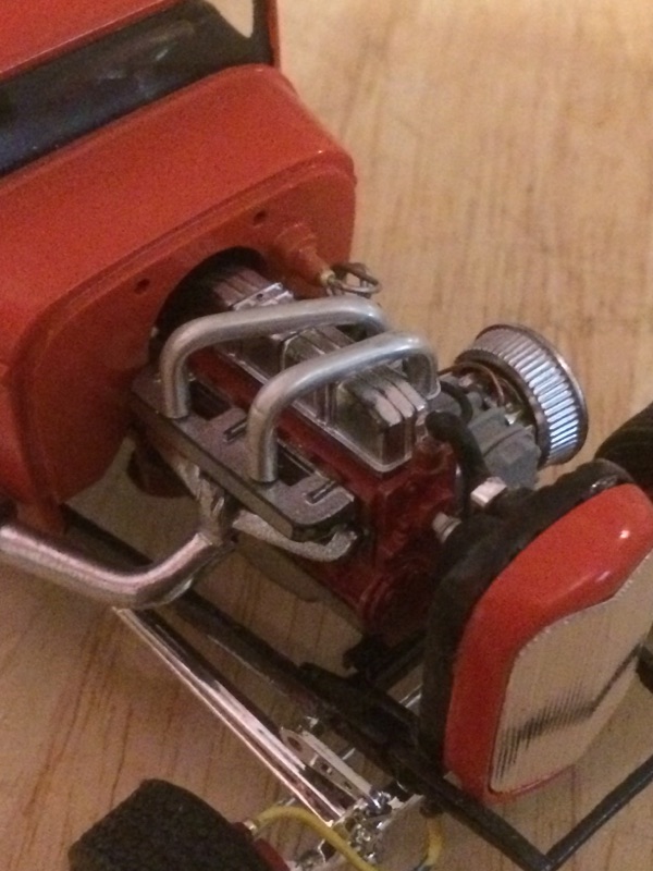
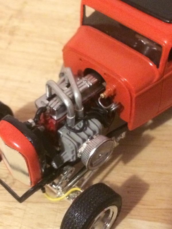
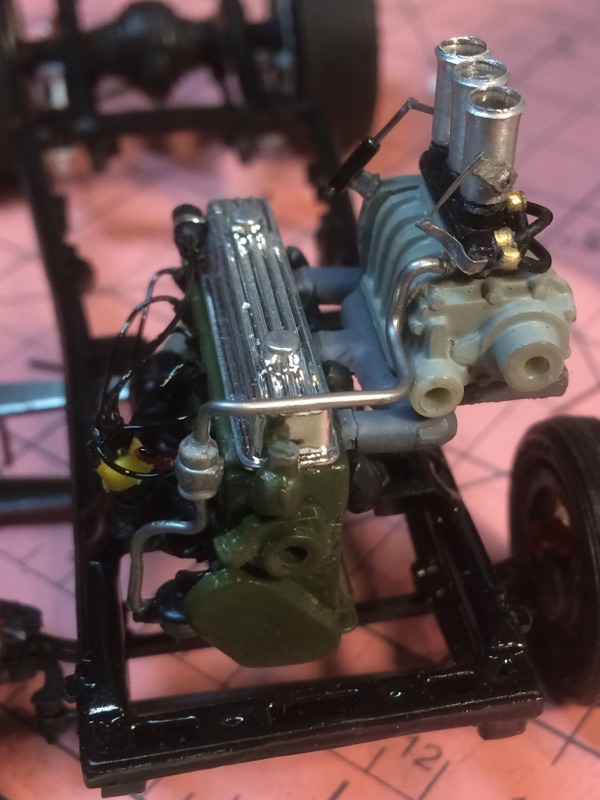
Getting some progress in on the engine, just about done with it and then moving on to the body and a little more frame detail. This is a shot of the passenger side. The wires are actually orange. Must be the incandescent bulb from a side lamp making them look yellow. Each wire is three pieces: a brass boot on the engine head, the wire, and a small insulation boot on the distributor, each wire having a hole in the distributor to park it in. The coil is on the side of the block at the front side. Also, just below the coil is the fuel pump. A line will connect to the pump from the gas tank, and from the pump to the fuel distribution block on the blower. I've found over the years that a bit of deception is sometimes needed when doing plug wires, mainly, apply your glue to the engine boot side of the wire and not the distributor. Anyone looking at the wiring automatically looks at the top of the distributor. All they see is clean(ish) connectors. Anyway, the pic of the plug side ....also added to this side is the starter/solenoid and a crankcase vent hose (not really accurate but adds to the 'busy') Note also a dipstick I made from brass rod and wire. The handle was painted red The driver's side shows the scratchbuilt blower mount, and the scratchbuilt exhaust manifold made from two regular exhaust units from a v8. I removed one of the exhausts from each and joined them together giving me a 1/2/2/1 manifold. I cut the collector end off one of them and moved it rearward a bit as the engine mount would have been in the way. It will have a single exhaust header And finally, I had to fill in the rectangle for the 8 velocity stacks that were to poke thru originally as I have to cut another one left of center to accommodate the new blower location. That's all I have for now. Comments and observations welcome.
-
final bit done on the blower, now on to the engine. Some pics This shows the L shaped pivot on the rear of the velocity stack. The spring connects to the blower case, the other side of the pivot arm connects to a 'moon' type cable, common on early drag cars, dunno about today. A cable will connect to the bottom of this unit, thru the firewall to the gas pedal linkage. ...and a front view. I redid the linkage for the front pivot arms. They were originally made from aluminum and were hard to see. Redone from thinned solder. a slightly (and only slightly) better view of the rear crank/pivot that will be put aside until the engine block is painted and detailed. More to come. Comments and observations welcome.
-
and the front linkage complete, though looking at it under hi mag, I may replace that spring. Funny, doesn't look that bad under normal scrutiny. We'll see..... Comments and observations welcome
-
velocity stacks permanently attached. I'll be having something to top them off.
-
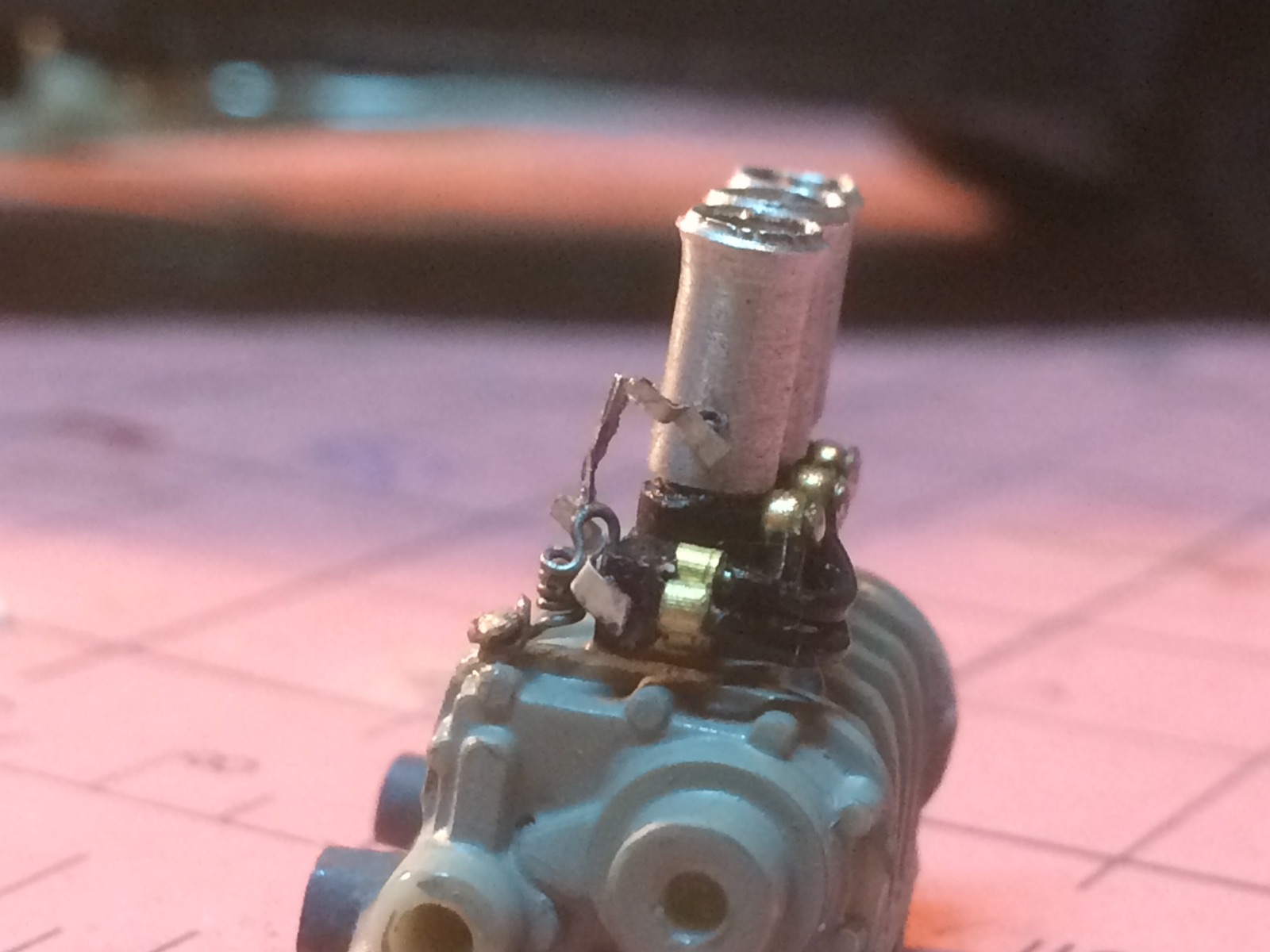
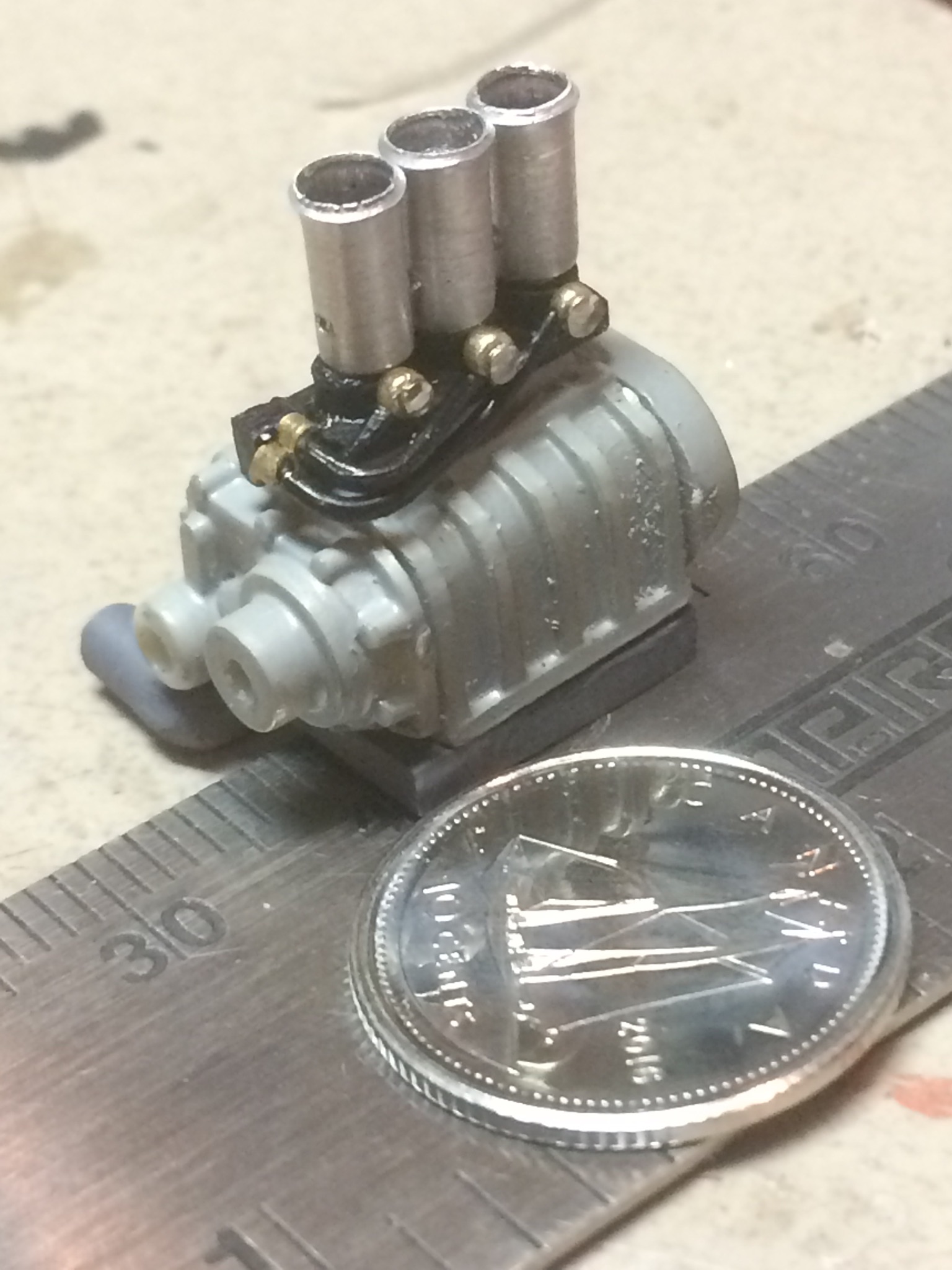
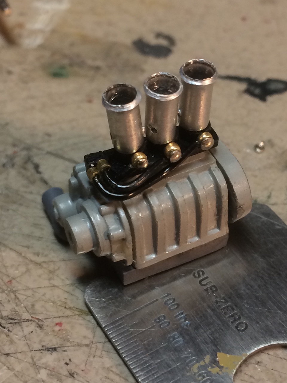
...and here's the unit with the fuel lines leading in to the injector manifold. The 'banjo bolts' were made with seed beads and capped off with snipped off dressmakers pin heads. The next items to make are the fuel inlet on the distribution block, the pivot shaft that goes thru all three velocity stacks, and the lever with spring on the rear of the fuel block attached to that shaft. The stacks are crooked as they're not attached yet. Just there for the shot. Comments and observations welcome
-
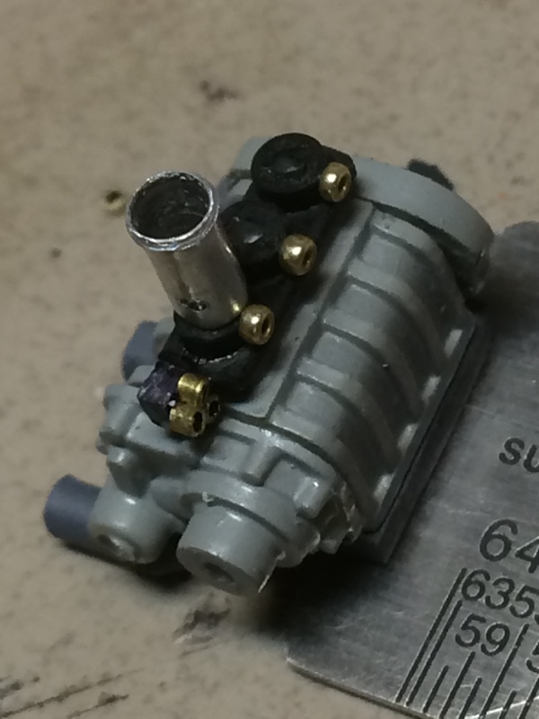
...and with the injector base I built. It's a piece of sheet styrene cut to size with three pieces of styrene tube cemented to it and again the rectangle filled so it looked right. I had some small 'seed beads' that I'm using for the banjo bolts on the side. The fuel lines will be glued to butt up against these. Then, the front fuel manifold block was made from another very teensy piece of styrene with three pieces of small brass tubing cemented to it. There will be another seed bead cemented to this block for the inlet, and an arm made to connect to the pivot rod that goes thru the ram tubes. You can see the hole in the one that's on there for mock up purposes. The manifold is done in primer grey, the blower in a light flat grey, manifold block in flat black and the fuel delivery block with a Sharpie. As always, comments and observations welcome
-
managed a couple of updates to the engine build. This is the blower stripped of chrome and with the injector tubes to get an idea of how it will begin to look..
-
a set up of how it will roughly look... and home made injector tubes I may or may not use observations and comments welcome
-
Got around to starting the engine. I've decided on using a straight six I believe is from a 50 chevy kit. Anyway, here's the engine....I drilled the 2nd hole on the left for a previous intake I was working on and scrapped. My first intake manifold was done with small(er) diameter styrene rod. Looked nice, but too small after looking at real world intakes. I made a more substantial looking one from sprue and a support plate shaped from some sheet styrene ...and here's what it is going to look like in mockup.. ...and further rough fitted to the engine. The blower is slightly out of focus, but the part that counts is the manifold. The header pipes fit one on each end and two pair in the inner spaces. More to come. Comments and observations welcome.
-
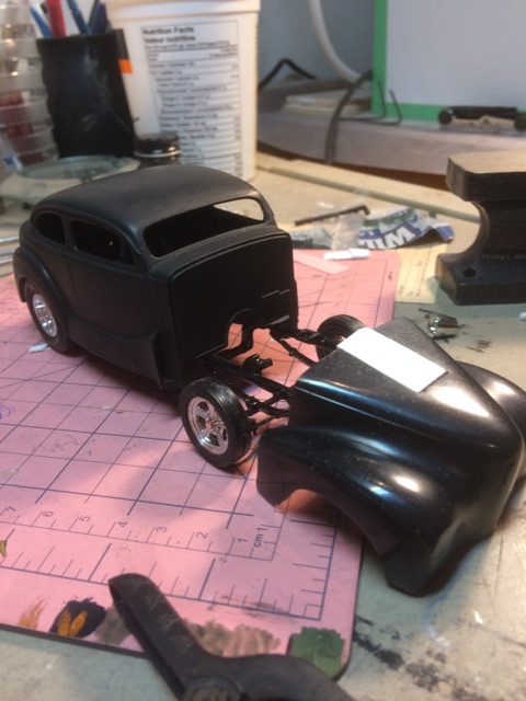
Tough finding time but got a little bit done on the back end. Still needs shocks ( I may scratch them) but so far has kit springs and ladder/wheelie bars from an old mpc Firefighter kit. I'll add shocks as mentioned, and shocks to the front. I'll then have a rolling chassis and most likely start the engine work . Comments and observations welcome
-
...and how she sits....
-
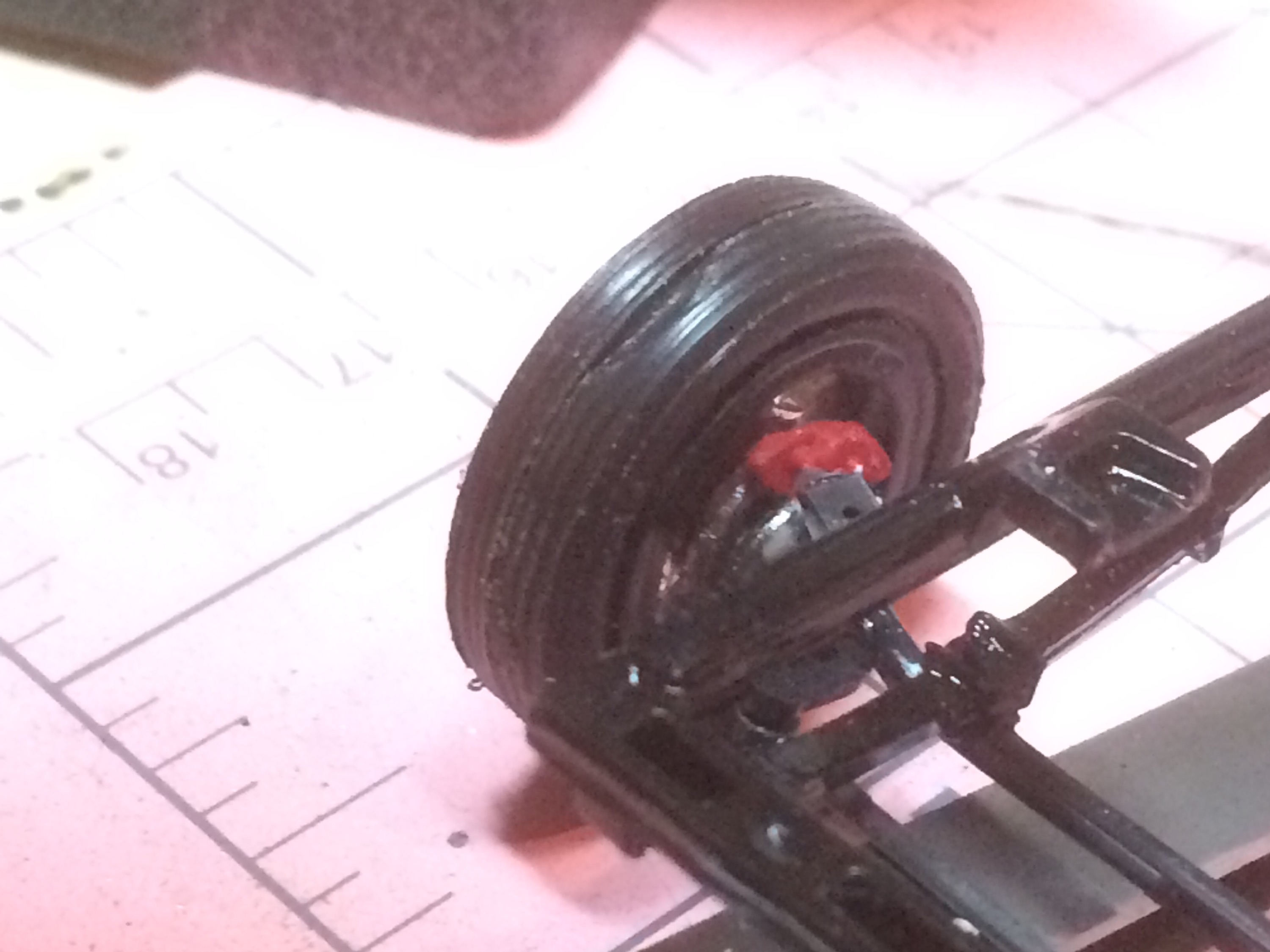
...and a shot of one of the front brakes...but that tire gotta go!
-
Looks like a killer in the making, Dan! Espo, I'm thinking of a blower, but I came across belt drive superchargers that were on old L-head and v8 flatheads back in the 40's and 50's. I've done some research and have gathered enough material to attempt one for a different look. I'll post progress when I pick up on the engine.
-
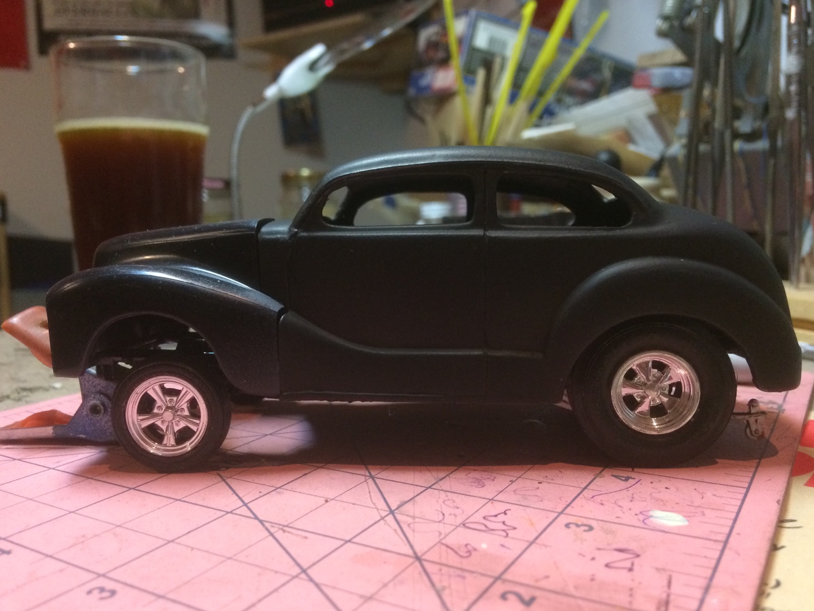
I had done a post months ago on how I did the chop to this kit. I've been away, now I'm picking it up as a wip. In the two photos is me setting the stance for the car. I've tubbed the rear by widening the inside fender wells and narrowing the transaxle to fit the tires under the body. The front is a dropped axle assembly (I believe its part of the kit -- it was a glue bomb when I bought it) but I turfed the wheel backings and made a couple of disc brake assemblies to replace them. Didn't like the supplied engine so I'm building a flathead from various pieces found in the ol' parts box. Probably to be blown with a 4 injector assembly. I like my gassers with a slight nose up stance but not a drastic one. Body color is leaning toward a metallic red. Comments and observations welcome.
-
I did this one with three shades of craft paint over a gold base. The black was rattlecan flat black.
-
Thanks for the kind words and observations everybody. The project is on hold for the next 3 months (snowbirding in Kissimmee till April). I have a Revell Orange Crate I'm bringing with me and I'll be smoothing out the flash/parting lines, opening holes and doing sub assemblies on it. Got the chop done on the Austin its finished -- but no pics -- and again, thanks for looking in. Hope I was able to confuse the issue.