Farmboy
-
Posts
518 -
Joined
-
Last visited
Content Type
Profiles
Forums
Events
Gallery
Everything posted by Farmboy
-

Paint Strippers - What to Use?
Farmboy replied to pbj59's topic in Model Building Questions and Answers
Isopropyl alcohol works!!! It easily removed(s) primer/color and clear coat paints on a recent paint job gone wrong. I used plain old 70% Isopropyl, poured it in to a sandwich bag with the body and related parts. A couple of hours later the coats just slid off. No plastic damage. After some minor cleanup in corners and stuff, a wet sand/reprime and I was back in business! -
....one more thing that's bothering me. in this photo.... ...and others, there is what looks to be a 90 degree shielded pipe on the front of the engine. Some photos have it on the right, others, like the red mustang, on the left side of the engine. I thought it might be an oil return hose but I don't think this car carried an oil tank. Could it be a crankcase vent outlet? There is only one in photos where it is visible, the unused side having a plate bolted over it. The block would need a vent somewhere. these usually had an in line oil catch can of some type, and lots had a pipe welded somewhere to the header to help in the vacuum, though not 100% did. Photos do not make it obvious. Any ideas?
-
I think After a lot of photo enlargement you are right. Guess I just have to make the half round gear cover. From my perspective the gear cover made it look — to me— that it was on the side of the pump, not on it. Thanx for the heads up.
-
-
The mag is driven by pump gearing but it’s beside the fuel pump on the engine held there by a bracket on the 1:1. The kit has the mag sitting right on top of the pump.
-
ok, here's what I've been able to put together from photos received and pics I also had on file. It's pretty simple, but it was a real bear to find lines that went from point a to b. Later model Malco's look like they had an electric pump (?) between the newer rad and engine. I ignored this. I also added a fuel return line from the valve on the blower. This was not on earlier generations but it could have been. The magneto is ok where it is, ignore the note. A gear cover is all that’s really needed if so inclined. The water lines in early versions were black hoses, later changed to narrow diameter metal tubing. I did not see a water pump There appears to be two oil lines (not in the diagrams) entering the lower front corner of the heads. I'm not sure on this so did not include them. oh, I called this the Un-Official Malco Gasser Mustang Fuel and Cooling System Plumbing Schematic". If there's issue or bad info in the diagram, let me know. I will amend it if necessary.

-
As best as I can tell there is no return or drain line from the injectors on the 1st generation build which is what I'm modeling but I think I will add one anyway just to busy it up a bit. I spent some time drawing it out and will note this in the post. I do not claim 100% accuracy as it is a bit confusing between photos and actual car years. I'm not building a replica as mine will be a pearl white without the Malco decals, but the up front plumbing is important. I'm planning a tut on the engine build for anyone interested.....
-
norm, I've posted a query on the diecast forum hoping for that very thing. thanx for the input.
-
....and of all the photos and links I had pertaining to the vehicles - he still had some stuff I hadn't seen before. Ya gotta love it! Thanx again to all that took the time to help out. I'm sure I'm not alone in my quest so I'll post a diagram/schematic of the fuel/cooling system when I have it done for those interested. I can't say it'll be 100% accurate, but close enough for home cookin'.
-
Anyone here have the gmp Malco Mustang Gasser? Got any pictures of how they did the cooling/fuel tank up front?
-
Casey, Force; thanx for the photos! some are are new to me and will hopefully add a little more clarity to the system, thank you much! Gassers are a favorite of mine, and the cooling/fuel delivery 'tank' on this gasser is different enough that it's worth the research to try to get it as right as I can. Armed with these and what I have I think it's time to try drawing out an 'imagineered' assembly and go from there. thanx again!
-
Glad you knew it was a gasser. The Malco Gasser has/had quite a unique fuel and cooling system arrangement, that's what I'm attempting to duplicate. An "Official Malco Gasser Mustang Fuel and Cooling System Plumbing Schematic" would be a worthy piece o' work. If I do manage to find enough info to do a relatively accurate rendition of the set up, you can be sure I will post it. And I'll probably call it The "Un-Official Malco Gasser Mustang Fuel and Cooling System Plumbing Schematic".
-
Afx —. It’s a gasser. Vintage at that. vamach —. Next stop is to contact Peterson museum to see if additional pics (beyond what’s already online) can be obtained. thanx everybody
-
Thank you for the link but I’ve already filtered through those 4 pages of garbage and nonsensical ramblings and it’s left me no further ahead. For instance, what is the function of the ‘near’ line that goes down on the left...is this a cooling crossover? How is the rad/fuel tank separated? Which ones are coolant or fuel? Return lines? The photos only hint at where the other ends may connect, let alone why. Other models I’ve seen don’t do much with plumbing and I would doubt the accuracy. Oh well. Thank you, but the search continues...
-
I've been looking for quite a while on how the fuel and cooling system was arranged on the Malco gasser, either the blue or red mustang. I've had no luck. All of the photos I've seen (1:1, die cast) show lines, but incompletely. Does anyone have a diagram of how the fuel/cooling systems were actually set up?
-
Thanx everybody for the kind words and observations. 'Preciate them all.
-
Rusty, that's good old Rustoleum Metallic Gold. I bought it for an outdoor project and found it works great as a base over primer, just this time its the finish.
-
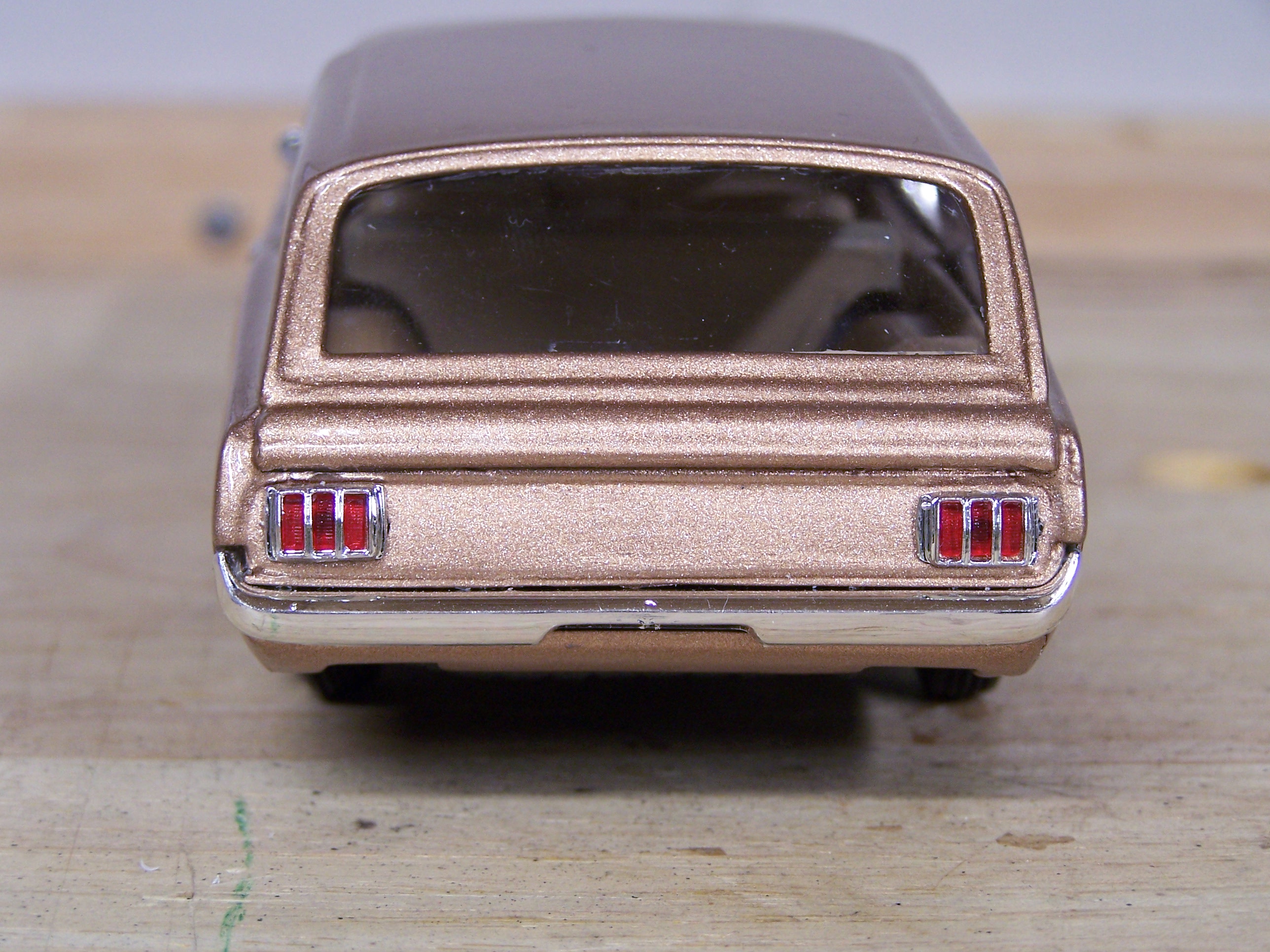
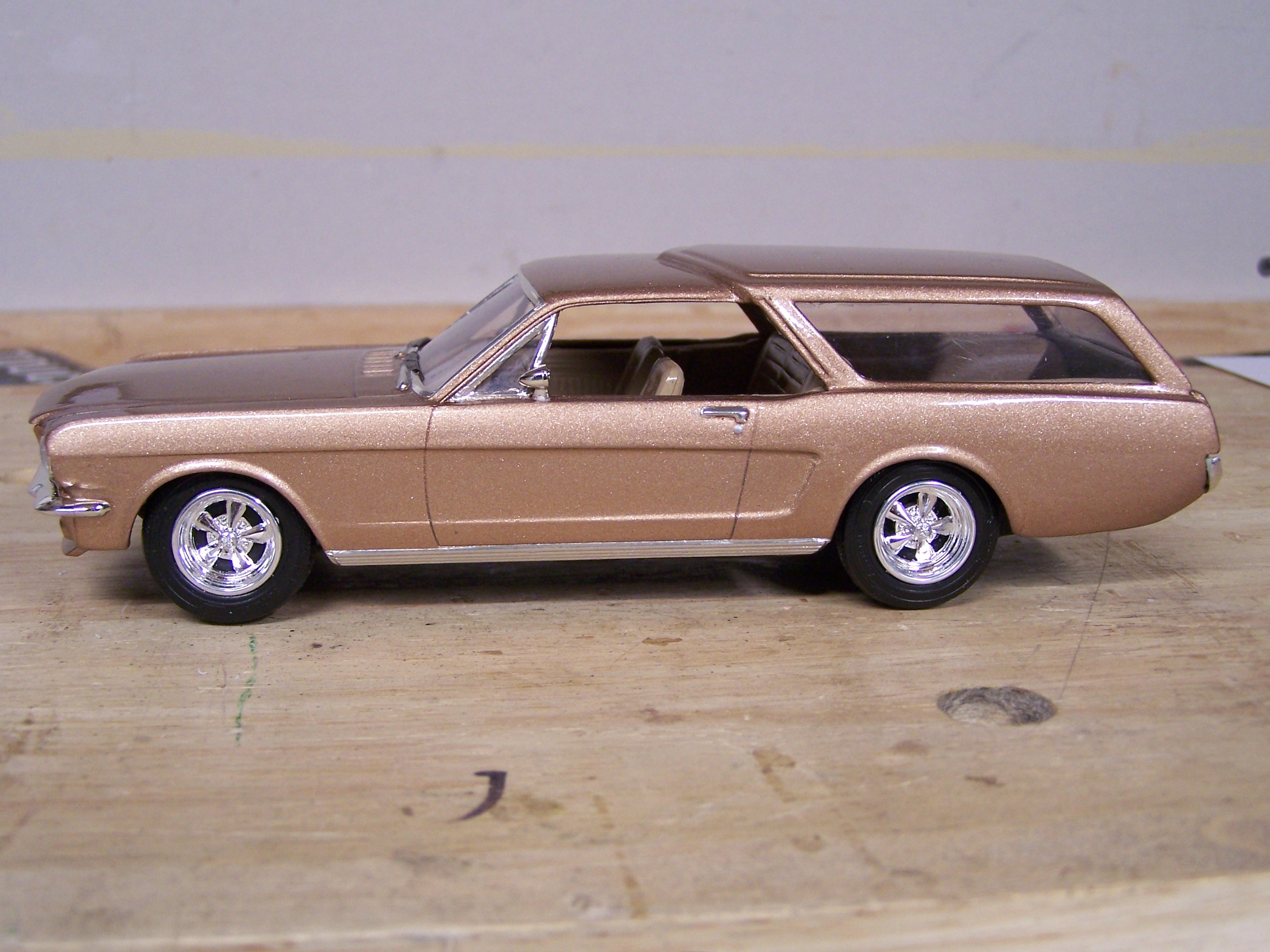
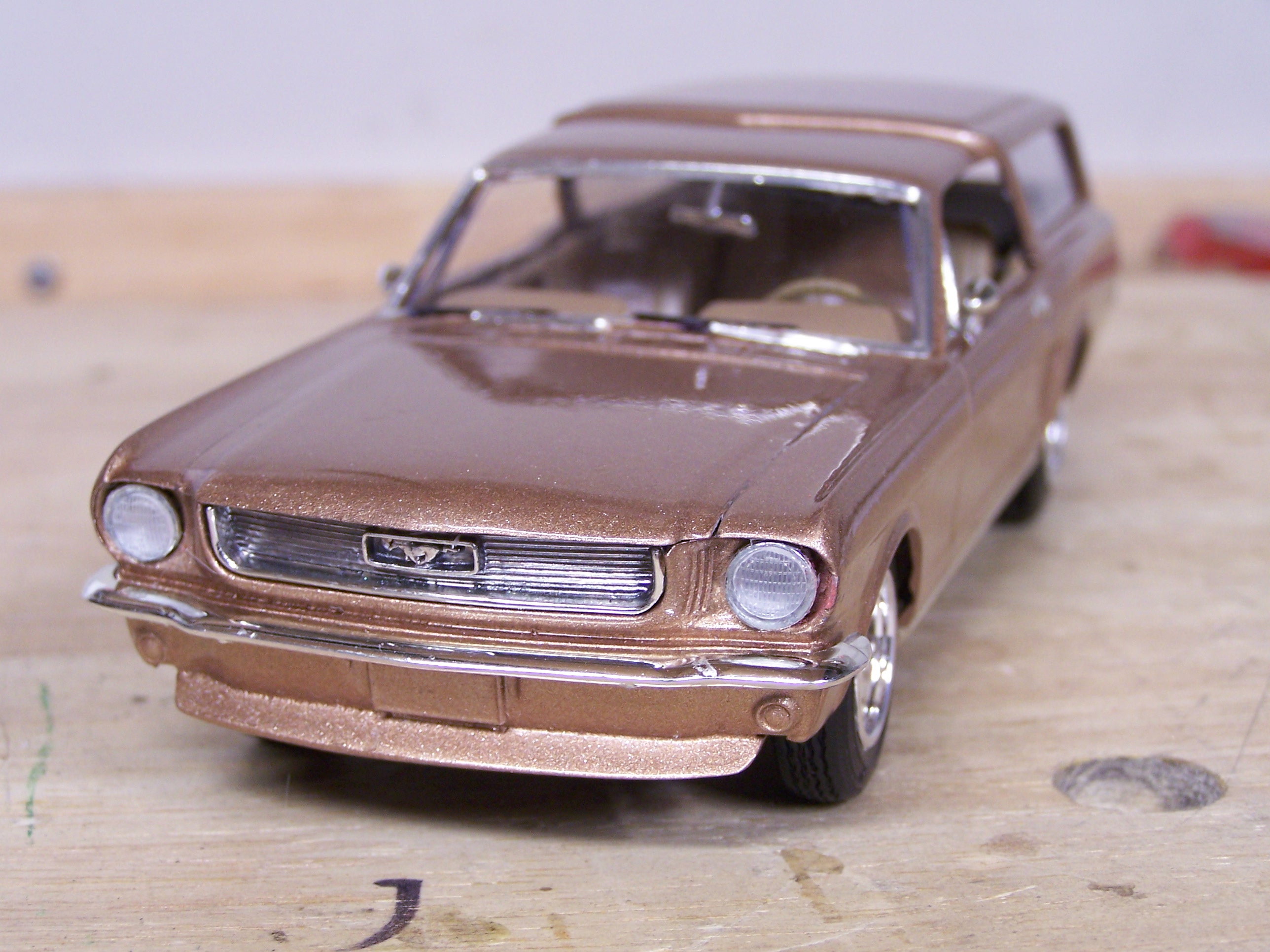
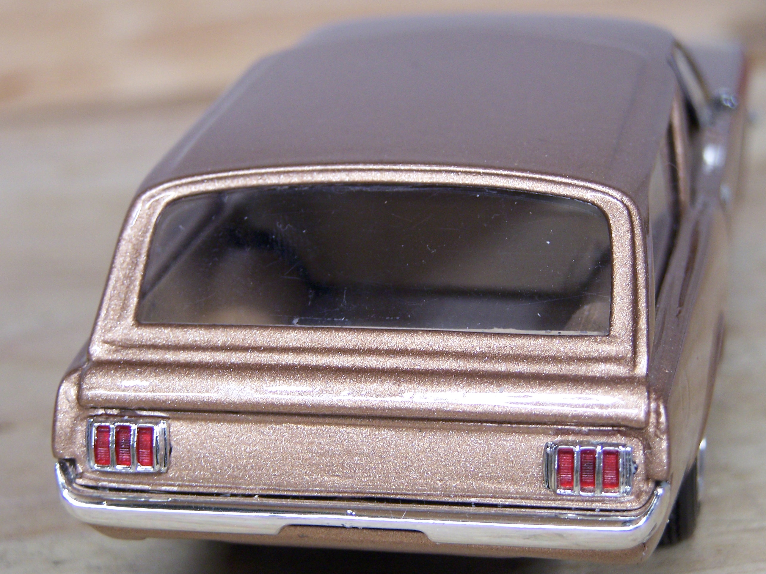
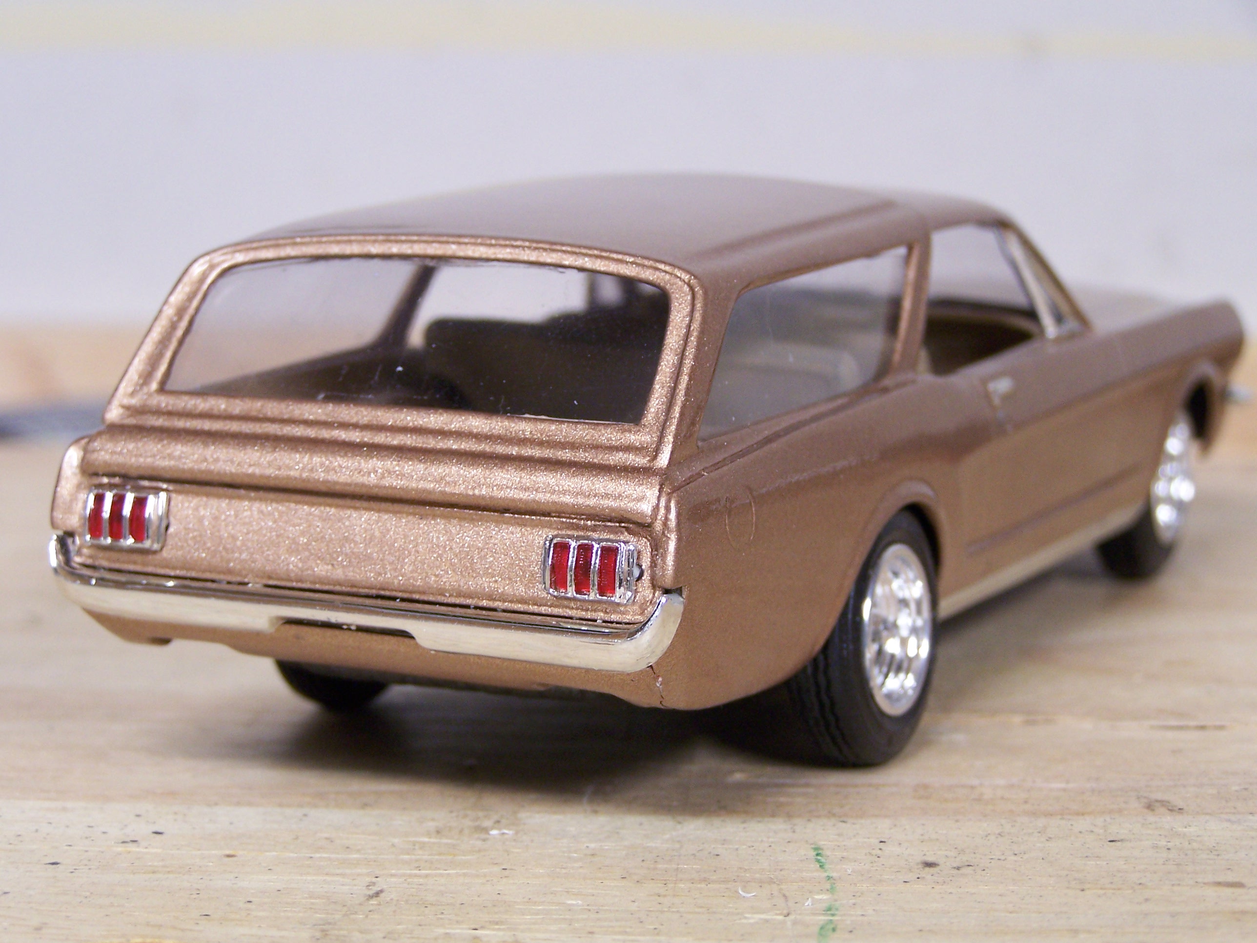
Finished this build last night, a marriage of two amt kits, the '66 Mustang coupe and a 68 Chev station wagon. Comments and observations welcome
-
...and here's the finished product. More in the Under Glass forum. Thanx to all for your input and observations.
-
Some of the nicest dirty work I've seen. Excellent!
-
..and some clear. My first plan was to do it two tone much like the later model big chevs and such, the two tones being antique white and an oxblood color red...but I thought it would look too busy so I stuck with what I had only planned as a base coat, metallic gold. . comments and observations welcome
-
I too had pondered moving the wheelbase and I would have for a 4 door. I had also looked at photos of wagons when a big car was a big car eg the 70's (any Columbo movie is a good reference lol). Virtually all have an exaggerated overhang. Plus I think it moves the wheel well to far from the fender hip, a major styling cue. But thanx for your insight....good stuff to ponder for maybe the next project. Here's base coat. more later.
-
.....the primer queen Still have the 289 badges to remove. I was going to leave them but no. Also have a gas door to scribe in the fender. Comments and observations welcome
-
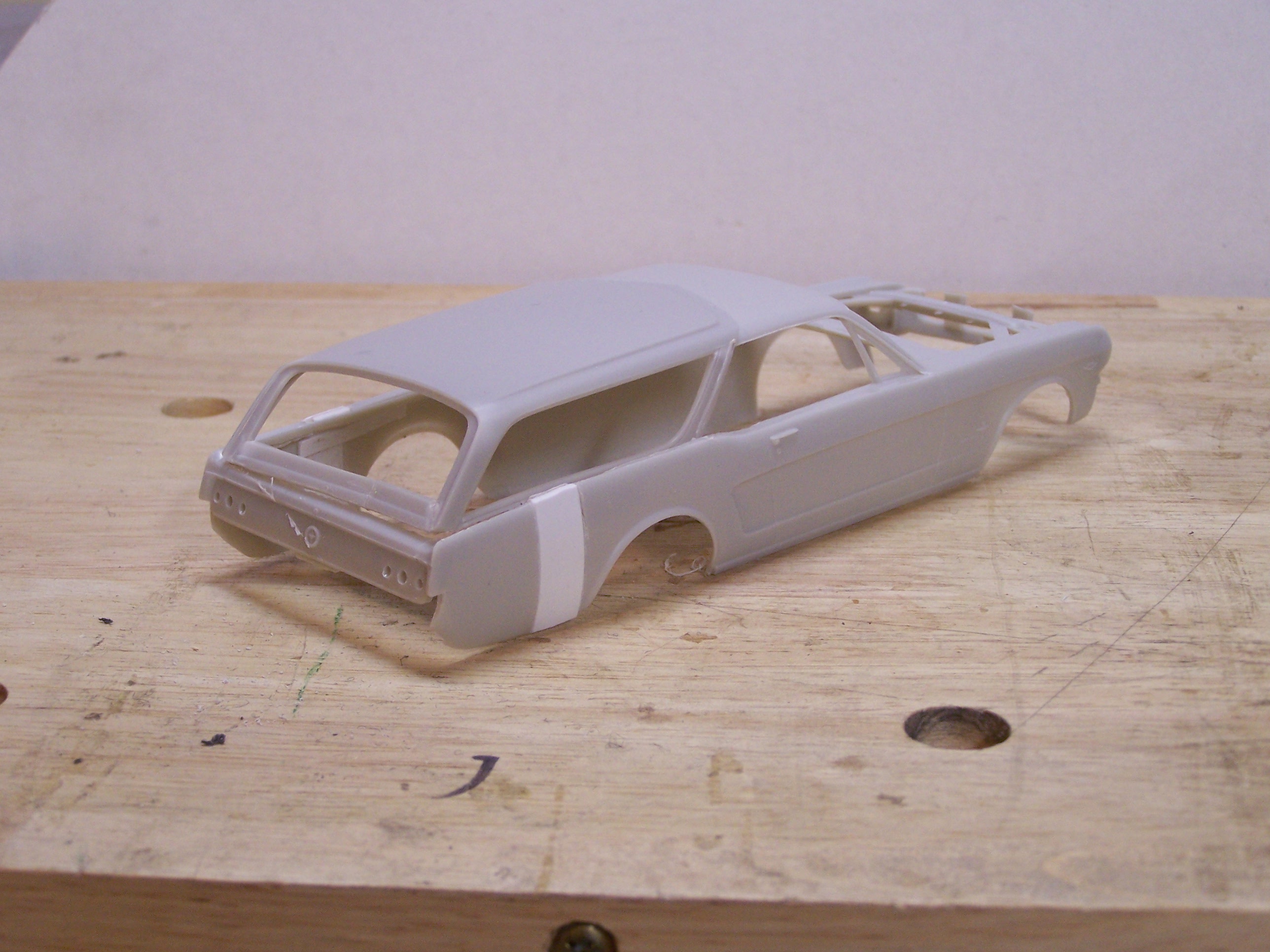
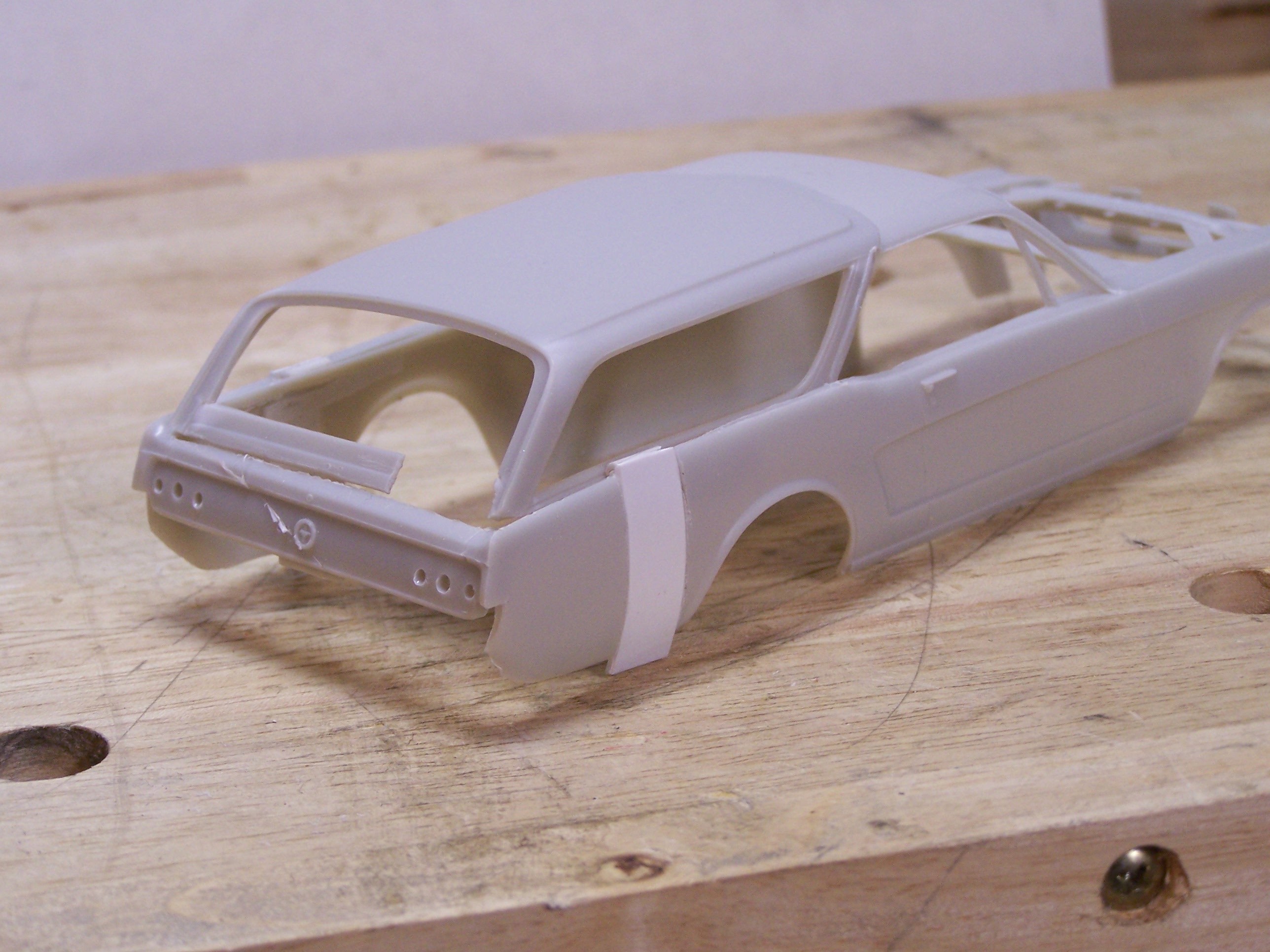
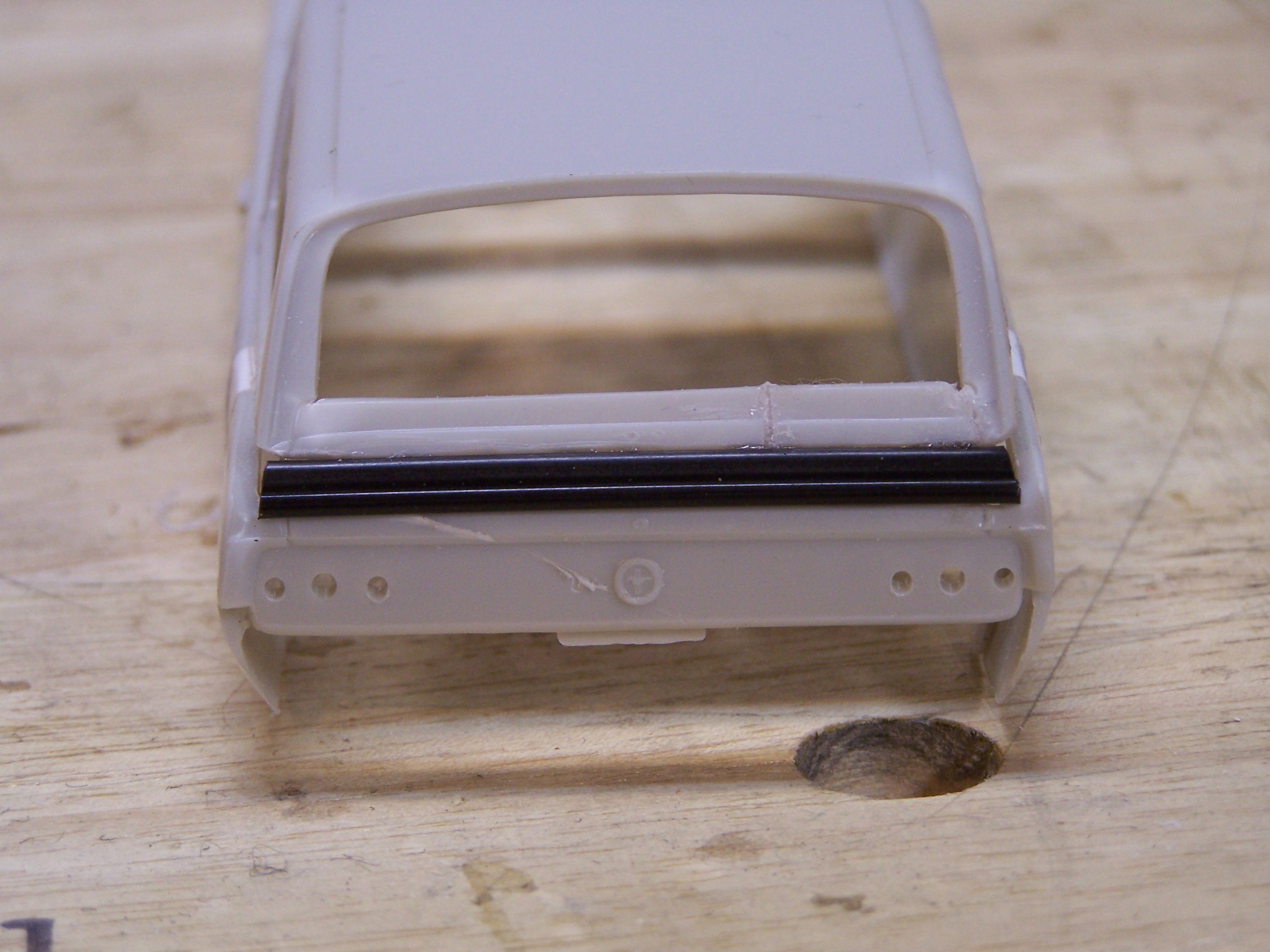
A word on the interior. I have no photos of the interior process though maybe I should have, I just honestly didn't give it any thought at the time but here is what I did in a nutshell. I cut the mustang tub slightly past the door edge so the cut lined up with the wagon's B pillar. I removed the rear of the wagon interior and butted it up to it to complete the tub making sure I cut it longer than needed, trimming to fill the length of the interior body. The vertical side joins were covered with half round styrene rod. The wagon tub and rear seat (a separate part) have to be narrowed to fit the mustang width. Again, a cut and fit process. A piece of styrene covers the floor in the rear of the wagon ...cut the rear seat in a near central seam to simplify the cut/glue/fill process. The floor pan for the mustang kit was used with no cutting needed as the wheel wells didn't change position, but, the molded-in shock/differential assembly pokes up and had to be ground down from the inside so the new wagon part of the tub sat level. A part of the floor at the mustang/wagon tub join also had to be ground away for clearance but the rear seat covers the surgery perfectly. It sounds complex but it's straightforward cut and fit stuff, and it's not the only way to do it I'm sure. The floor pan can be extended with a piece of styrene at the rear if one wishes. I used the custom rolled rear body pan so the opening is minimal. Your wagon glass won't fit. I made mine from clear stuff (acetate?) that was part of a chocolate Easter bunny package for a niece. The mustang windshield fits however it cracked while I was snipping it from the rest of the unit. The one time I didn't use my dremel to grind it apart!! Anyway, made it from the same clear stuff as the other windows. It relates. By the way, comments, observations and questions on the build are welcome.
-
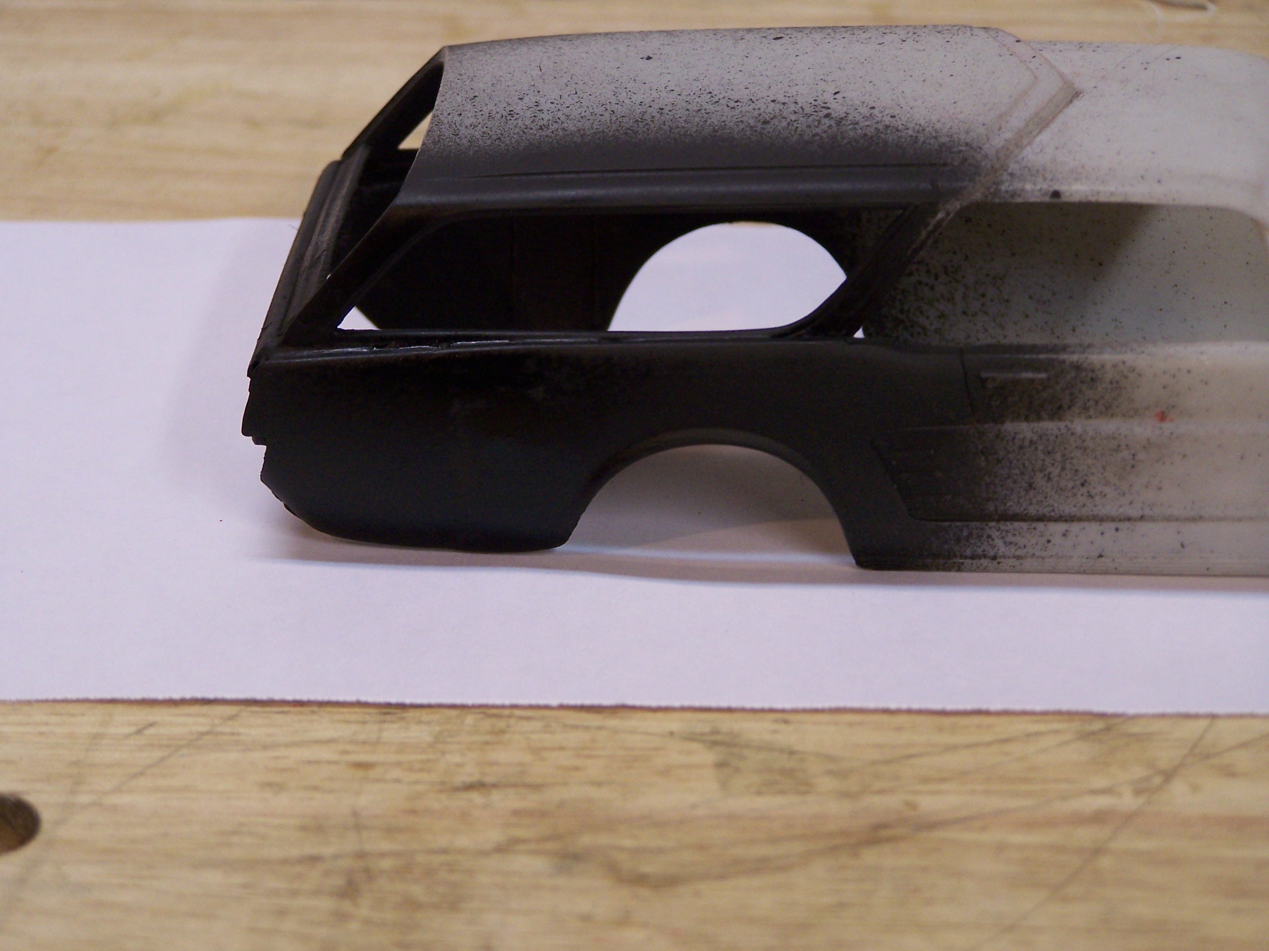
omg, my mom had a vega -- 2 speed auto! I remember driving it lol. Anyway, a couple of views of the body before bodywork; even the best laid plans..... the 45 I had cut in the rear window frame corner to help with horizontal alignment let go. Momentary drawback. Oh, and the pretty knife gash across the rear panel, a small adventure into 'out there' styling lol! See also that the plastic insert is 'v'd into the fender line. It gave me a rough guide of where to file and blend the top piece in. Here you can see some of the interior bracing around the sheet plastic inserts. Even then, I managed to open the seam a couple of times as I was adjusting the bottom of the wagon piece to the mustang fender. I wanted to keep a groove begtween the bottom of the window frame and top of the fender line.Super glue and good old tube glue to the rescue. It hasn't been cemented it this pic yet so it appears crooked but it really isn't. Here's my solution to a smooth transition from back plate to lift gate. A section of plastic stir stick from a coffee shop. It's in scale and gives it some strength to hold the back end secure during the sanding and handling. I'll fair it in to the rear end as a beauty line. Laugh, but I think it works! The messy stuff begins. More to come.