Farmboy
-
Posts
518 -
Joined
-
Last visited
Content Type
Profiles
Forums
Events
Gallery
Everything posted by Farmboy
-
Oddly, I don't have a lot of control over picture sizing for some reason. Tablets are a pain. Next build will be done on a laptop and pics from the Canon.
-
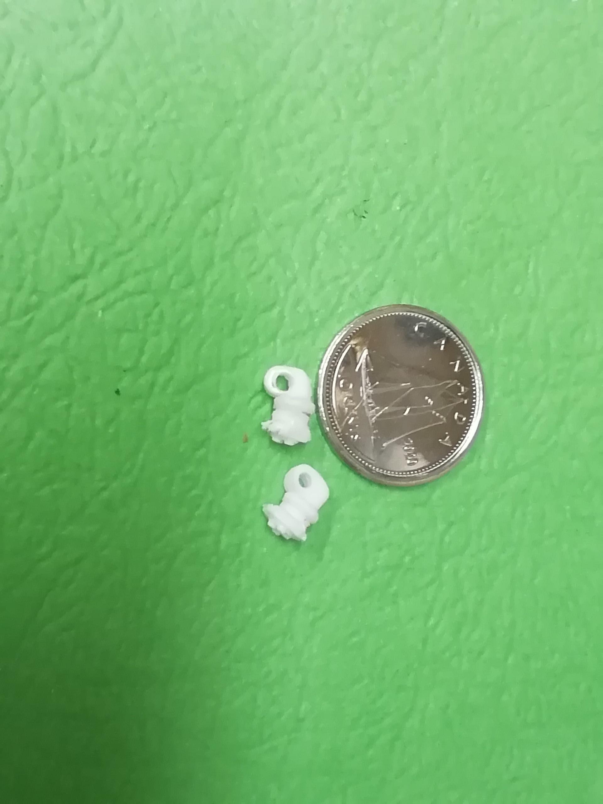
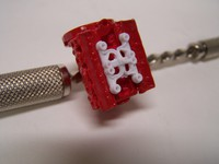
Only a few items left to cover. Let's deal with the fuel pumps. I felt they were quite a bit over scale so I made them a bit smaller. This is not necessary but I'll show you what I did anyhow. In the shot below, the top piece is from the kit unaltered. The round pin plugs into the manifold, then the magneto fits loosely into a hole on the top side of that pin. Not very strong if you're wiring the mag. The bottom piece has the body shortened and a hole drilled thru the mount, eliminating that pin. (I replaced the pin on the bottom of the mag by drilling a larger and longer piece of rod). Now, when the magneto is installed, the new pin goes thru the hole and into a deeper hole in the manifold for a secure joint. Make a few 90 degree elbows and tees for the fuel lines I'll do a diagram at the end of this thread showing fuel line connections.

-
I guess Tom was as much a showman as a driver. I think that piece really draws a person in!
-
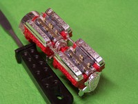
If you're including the shafts for the injector banks take note that the pin joins to the engine behind it on the inboard sides only. See the photo below. Do not confuse the pin shaft with the bigger engine braces.
-
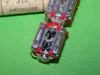
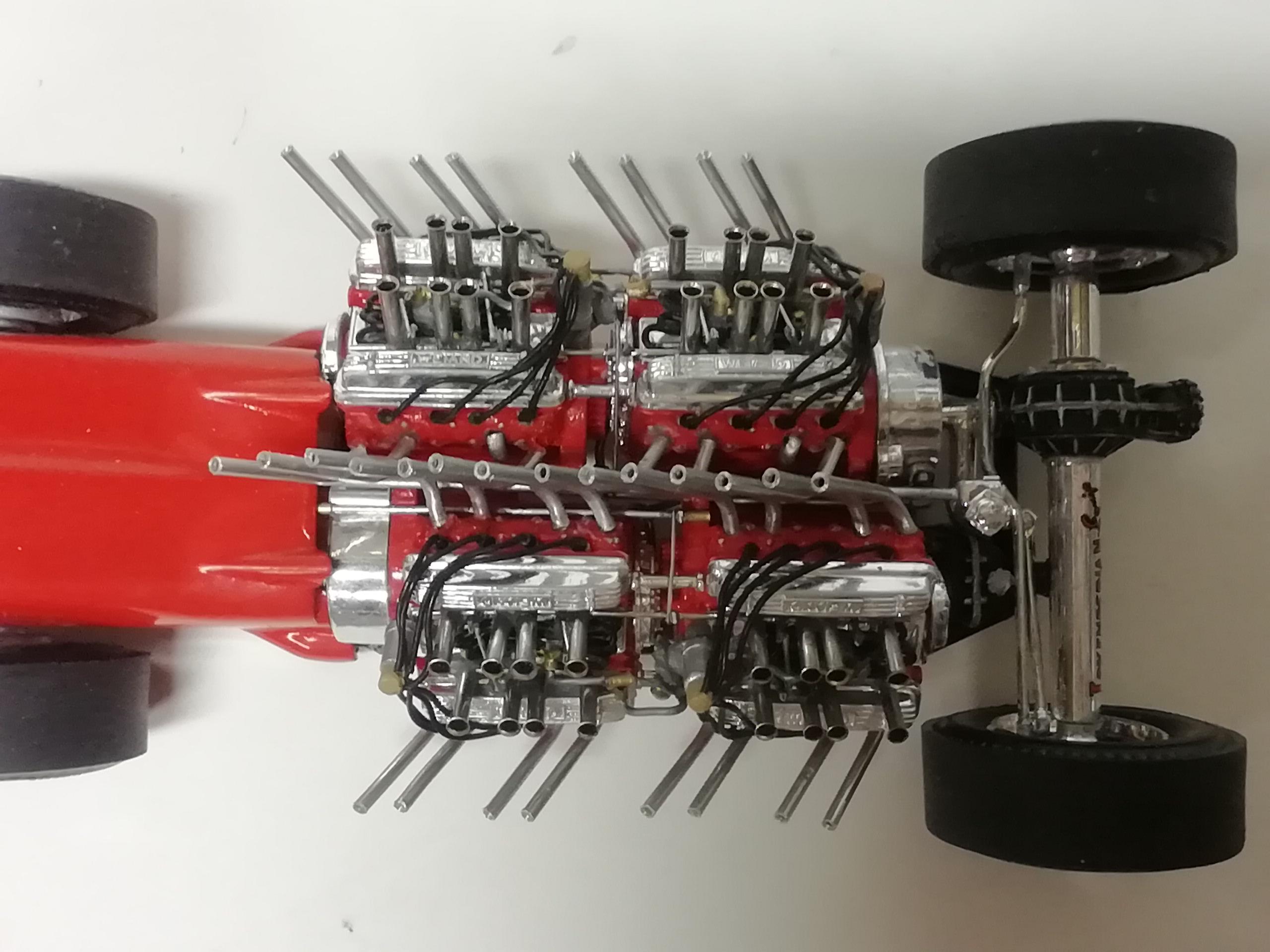
I know I've included this in the wip thread but I think it should be included here. If I could only add one detail to the model it would be this piece. It is a very very obvious line that runs from the top of one distribution block, and ends on top of the next. From the left the line begins with a 90 deg elbow on top of the distribution block and has a vertical hump in it to clear an actuator arm. Next it has a series of hard horizontal bends to navigate around the magneto and ends at the tee. A short length comes off the other side of the tee and bends 90 to end with another elbow on top of the 2nd distribution block. Repeat for the other engine bank. If this is all you plan to add, then simply forget the hump and tee sections and make the entire line in one piece. A dab of brass paint on both ends completes the look.
-
Oh, in case this is of any helps, these are injection banks with the slots cut in to them
-
Hey Alan, here are two additional pics for you You'll note the hard fuel line completely obscures the distribution block so I sketched it for you Hope this helps. Regards Mike V
-
To my embarrassment Alan I agree these are crappy shots that were done with my phone at the time. "...of the finished job...". I'll retake a couple of shots close up from directly overhead. Ignore the linkage and it will make sense. My sincere apologies. Regards Mike V
-
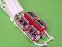
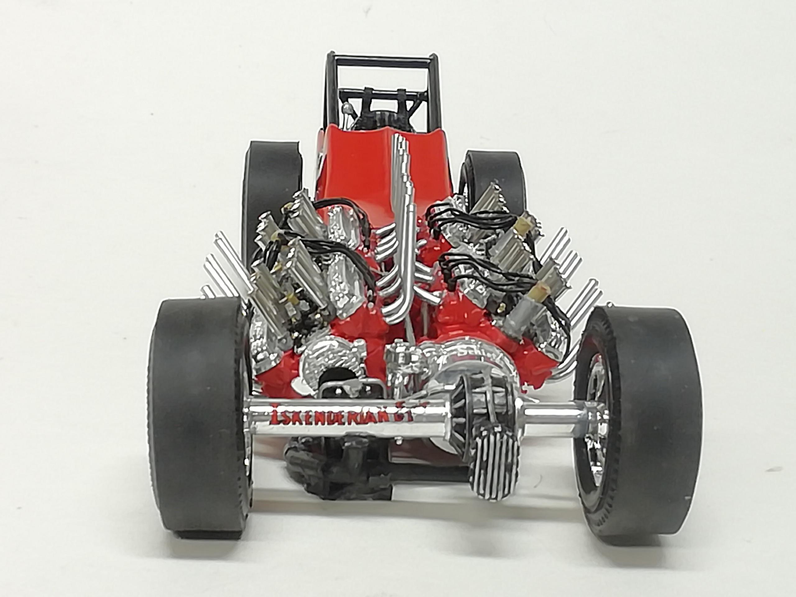
I used 'seed beads' to represent the fuel inlets. The fuel line itself attaches to the side of bead, not the open end. Don't worry about the opening, I found it's not really visible when all is said and done ....and just for perspective..... And the quick mock up. The injector banks are about 1/4 done as there are still velocity stacks, fuel lines, and injector shaft/linkage to add. Now it's on to the small stuff. You'll need 4 distribution blocks, each drilled out for 8 lines, a topside hard line, and a side throttle lever To mount them, simply glue them to the center valley cover, or for a sturdier unit make a mount like these below from aluminum. They're as wide as the block. Cement it to a block down one side, bend 90 degrees and glue along the bottom of the block. The length is cut so that the free end is cemented under an injector bank and is long enough to have the block centered on the valley cover. A dab of ca makes it secure. In the shot below, notice (besides the fuel lines) the blocks are not centered front to back on the individual engines. The block needs to sit in front of a gap in the velocity stacks to allow for throttle linkage. Not doing linkage? Don't worry about it. 32 injector lines. Whew. Comments and observations welcome.
-
Trevor thanks very much for the shout-out, much appreciated! I also found the ferrules quite adequate for my needs, glad you concur.
-
Thank you Slusher.
-
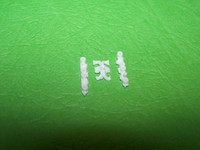
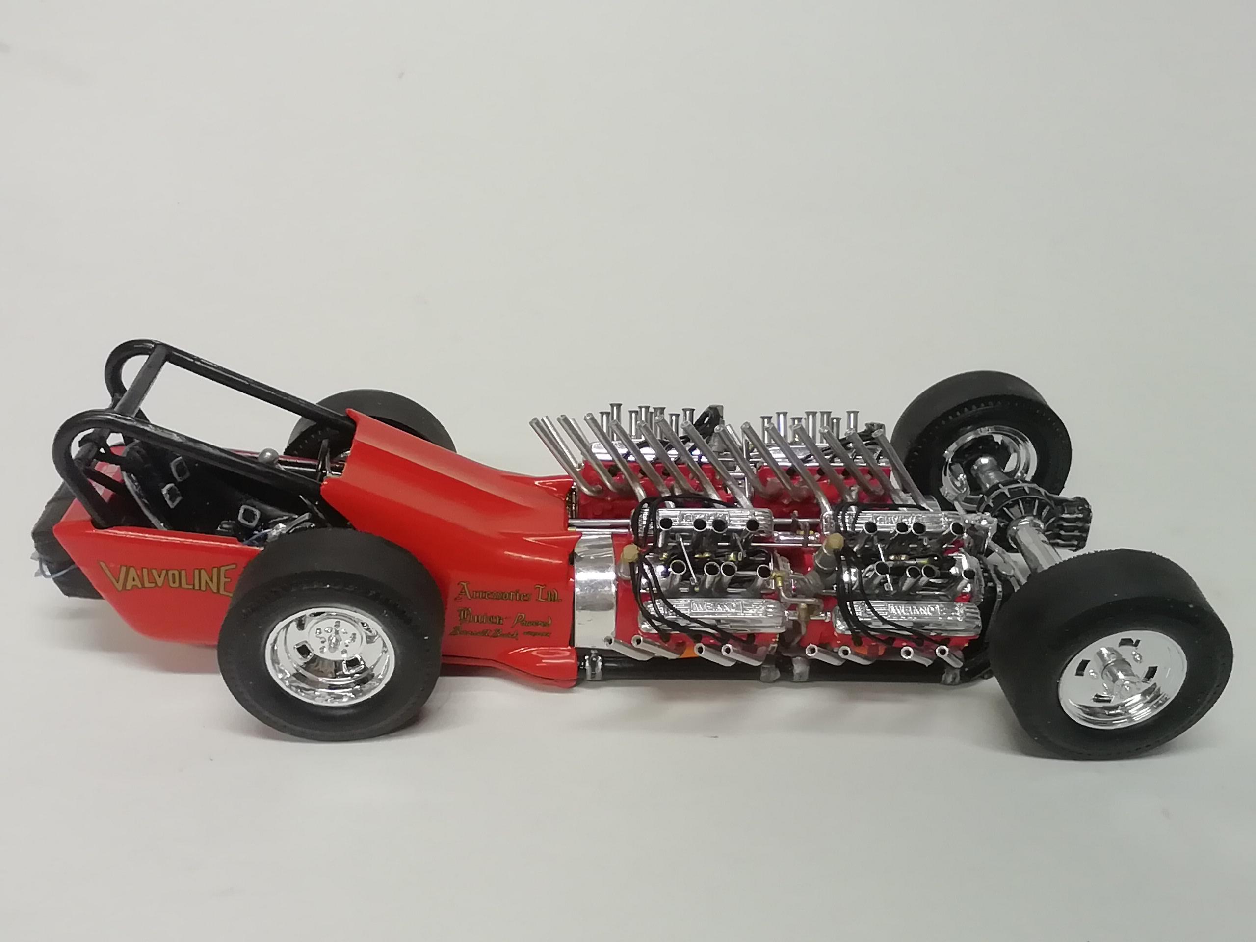
By no means is this the final word on engine plumbing, but it's how I did Ivo's car. Hopefully it may be of some help to anyone wanting to include any of the 4 engine fuel delivery details. I relied on Ken Foran's spectacular brass large scale scratch build and on line vintage photos of the real thing. This is the injection assembly supplied. By itself, 50+ years later it's still a beauty of a part. Painted black, given a wash and some drybrushing, IMHO, it would look great! I simply like to try to do things myself. Here's the unit disected. The center is discarded and slight mods done to the remaining two injector banks I've attached all 8 banks to a strip of painters tape and shot them a dark gray. These pieces get small real quick! My first alteration was to saw a groove across all 4 injector bases with a razor saw deep enough to take a length of a straight pin (you may need to widen the slot with an xacto blade). Here you'll see a mock-up of how the ferrules will sit on the base, the pin not interfering with the ferrule base. The pieces are so small it appears the pin shaft has been drilled thru the bases. They are not yet cemented only standing for the shot I'll have more soon. Comments and observations welcome
-
Thanks for the generous kudos on the build Dennis. One more out of the stash and on the shelf!
-
Thanks Mike. magic muffler supplied a picture showing slight changes to the showboat interior after it became the wagonmaster MM would occasionally wrench for Ivo and the current owner. Nice bit o detail to have. Thanx for the shout-out Dragline. It's not a beginner kit fer shur, and specifically the kit center row headers will give anyone problems using the jigs supplied (do the center ones on the model one by one), but get past that, and with a bit of building experience you'll have a satisfying model for the shelf without too much problem right out of the box.
-
Hey Echo, thanks for the shout out! I'm glad the kit turned out ok. ....Wait until you show this to someone totally unaware of the car and it's history! Way to go.... Robert, about 95% of the reactions I've gotten from friends has been "what the h*** is that!". .. but my wife thinks it's cute lol. Thanks Rodney. If you find the kit get it, it's worth the time if you have some experience. Tooold, I added the build here as it's such an old kit, but I've never seen one built on line. I thought there would be a number of modelers who could relate to it and would enjoy seeing it done. Thanks for the kudos, much appreciated!
-
Keep everybody in the loop Marcos!
-
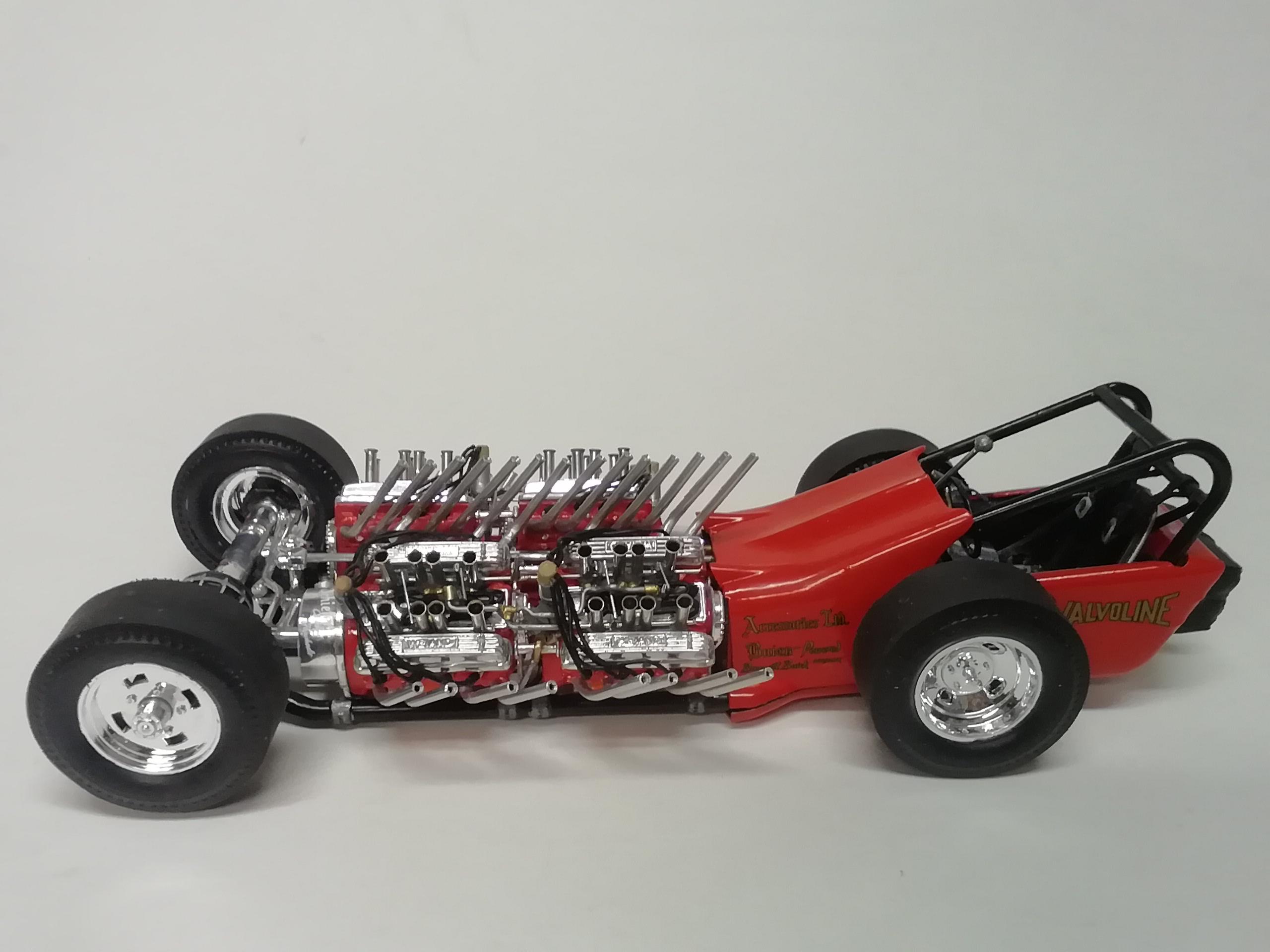
Thanks everybody for passing along the kind words, happy the model turned out! Lucky, the pipes are indeed small diameter aluminum tubing. A description of how they were done is in the build thread. The velocity stacks are metal ferrules. I ordered them as a kit of a few hundred in varying sizes and diameters, super cheap. Actually I'm getting my photos together for a short thread on how the fuel system went together -- including the stacks.
-
Photos posted in the Under Glass section. Thanks again to all who stopped by during the build
-
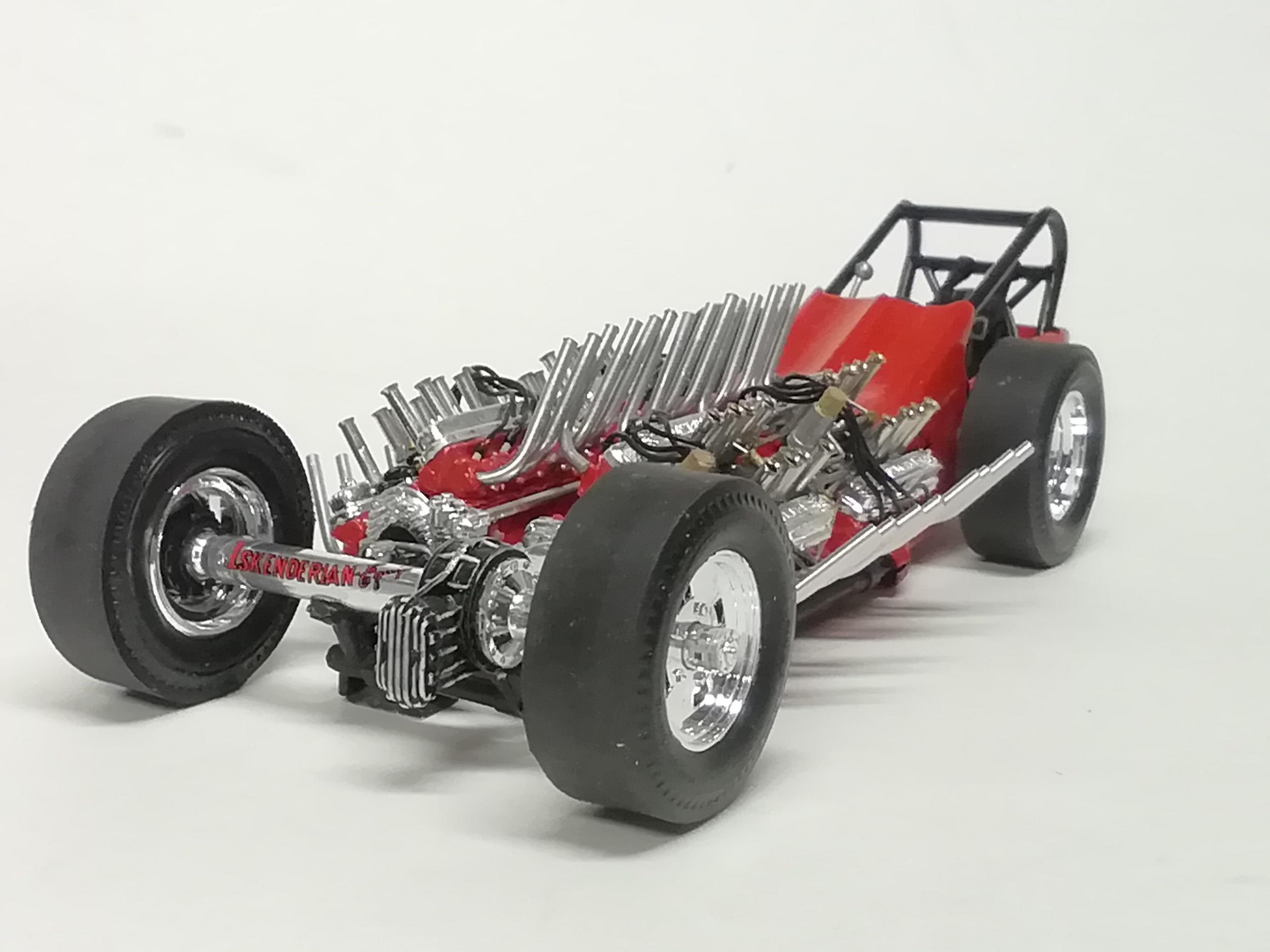
Finished. Added some detail where I could. Still a looker right out of the box. Comments and observations welcome.
-
Pierre, standing next to 32 pipes roarin' wide open would compete with just about any rock concert sound level I've attended I'm sure. Post your progress Marcos as I'm sure there are plenty of people that need that push to start their own builds. Model builders are where you find them Ian. Thanks for the shout out!
-
Well Brandon, I don't know if magnificent fits, lol, but thanks much for the kudos. I believe I have progress photos on my other laptop for the fuel distribution setup. While not the final word on engine detailing I'd be happy to post a separate thread to show you how I did things if you think it would be of any help to you. I paid attention to this part of the assembly as it's basically the draw for the car.
-
Thank you sflam for the kind words.
-
Many thanks cobraman, I say again, even as an out of the box build, with a little care it would look great on the shelf.
-
Thank you Marcos. Maybe the build will be of some reference help when you do your restoration.
-
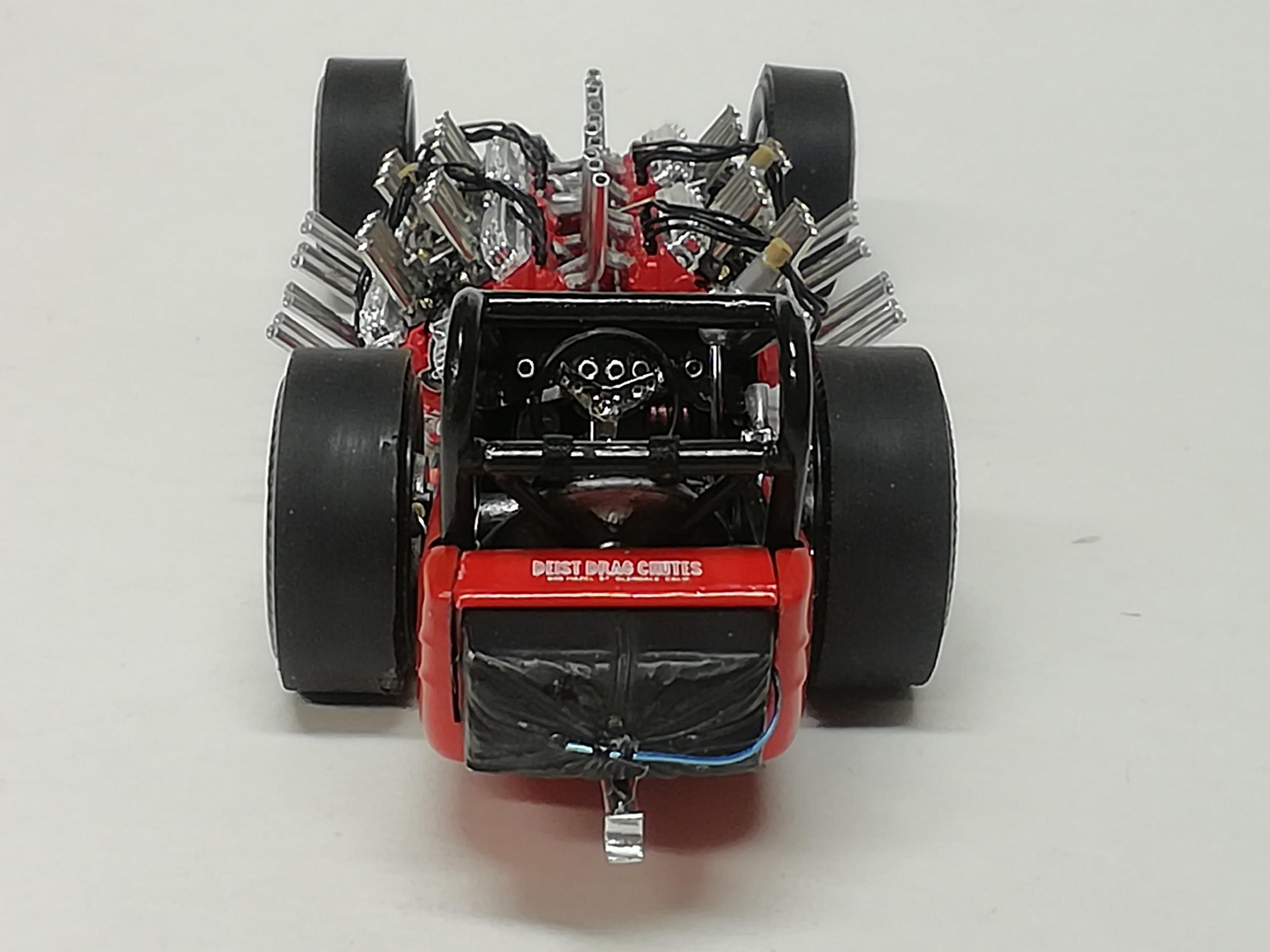
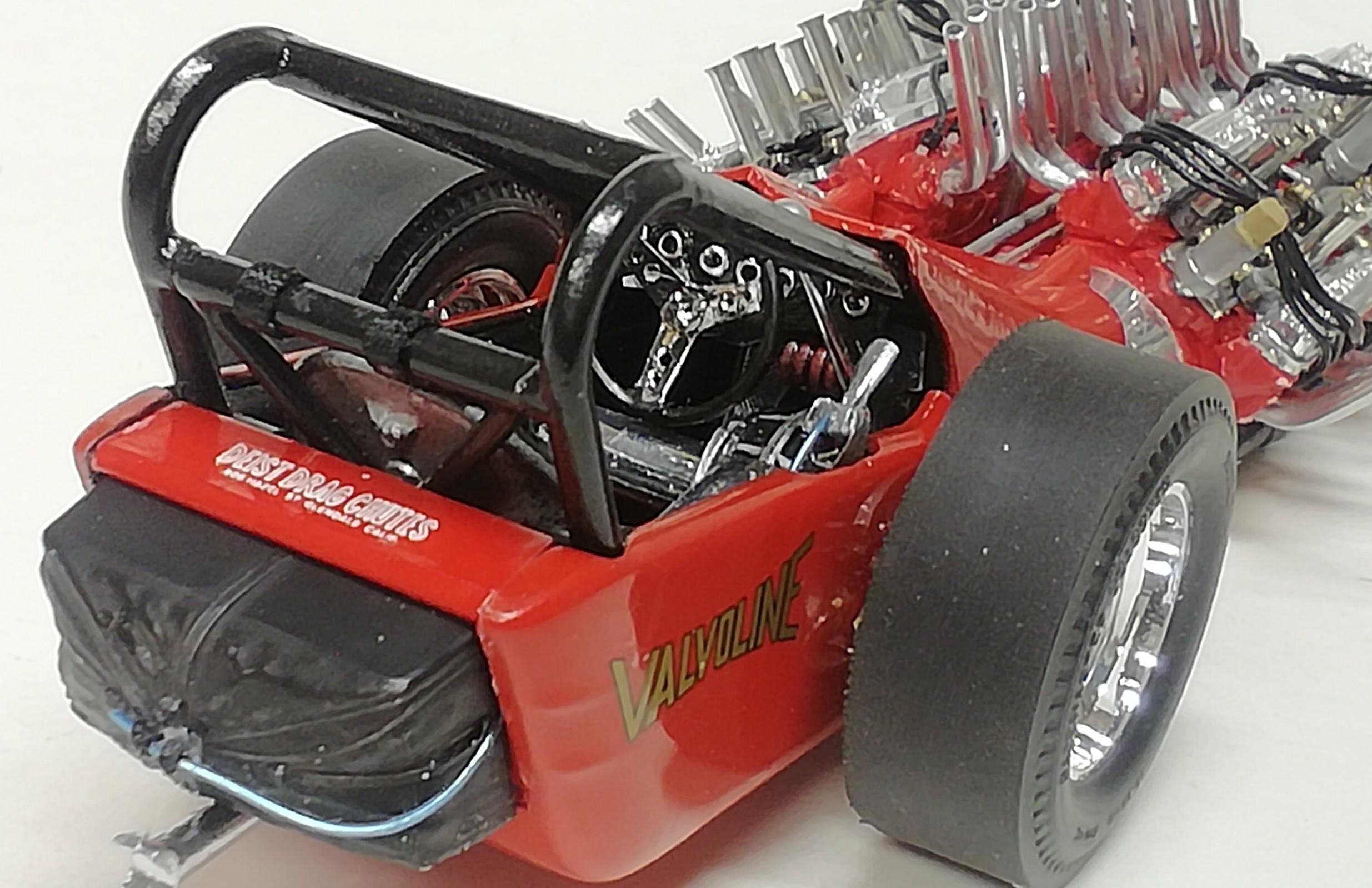
Thanks for your good words on the build Joe, so glad you enjoyed the build process. Billy, keep the stories coming! Very interesting stuff! Nice shot of the cockpit...shows I got most of it right. It's the first I've seen of the ring for the chute release, brake lines are more visible, and that's some interesting bit o' snake bending for the brake lever! I agree the seat needs a bit of lovin' but all in all its the same machine. Thanks for the pic!