Farmboy
-
Posts
518 -
Joined
-
Last visited
Content Type
Profiles
Forums
Events
Gallery
Everything posted by Farmboy
-
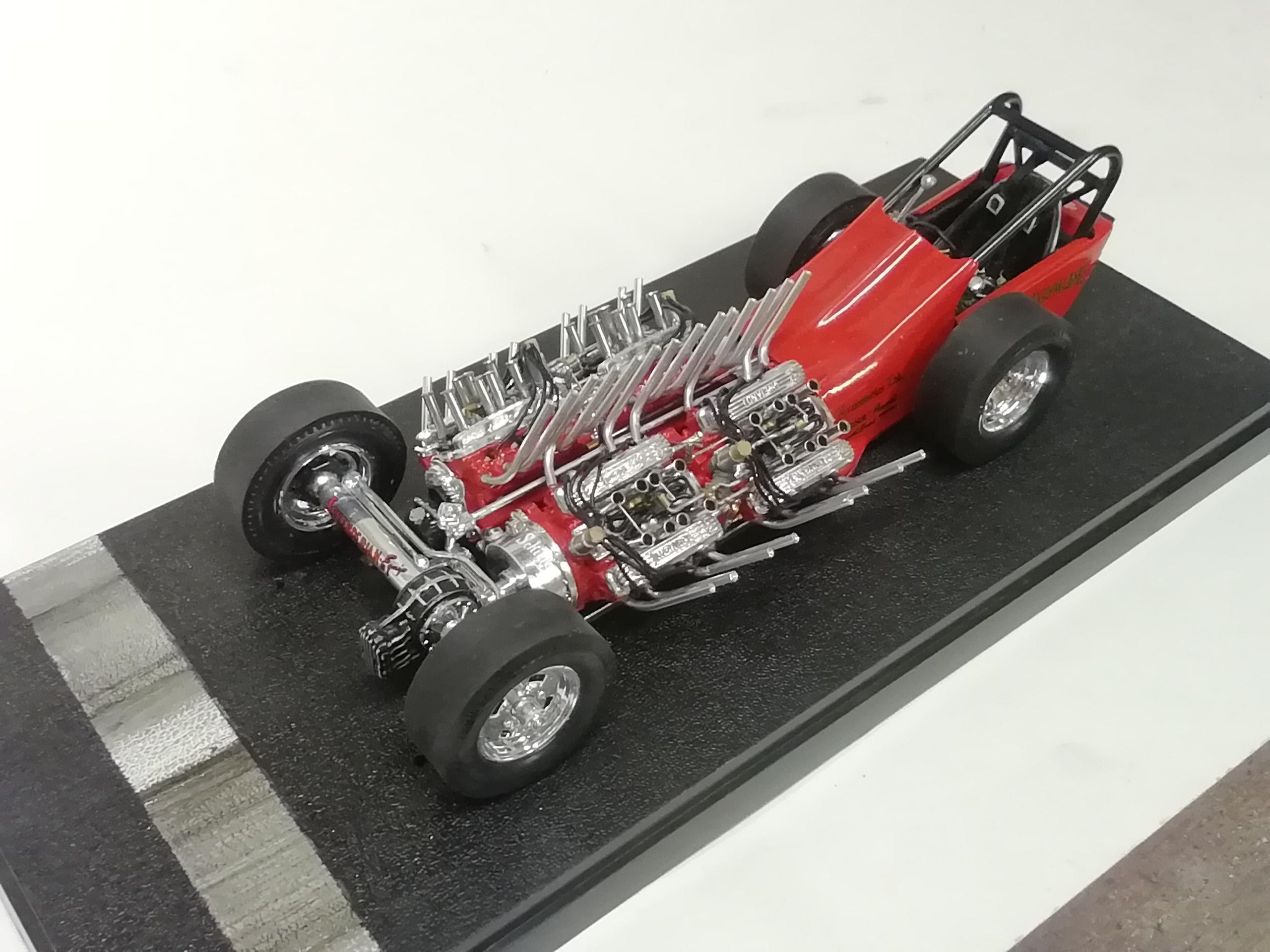
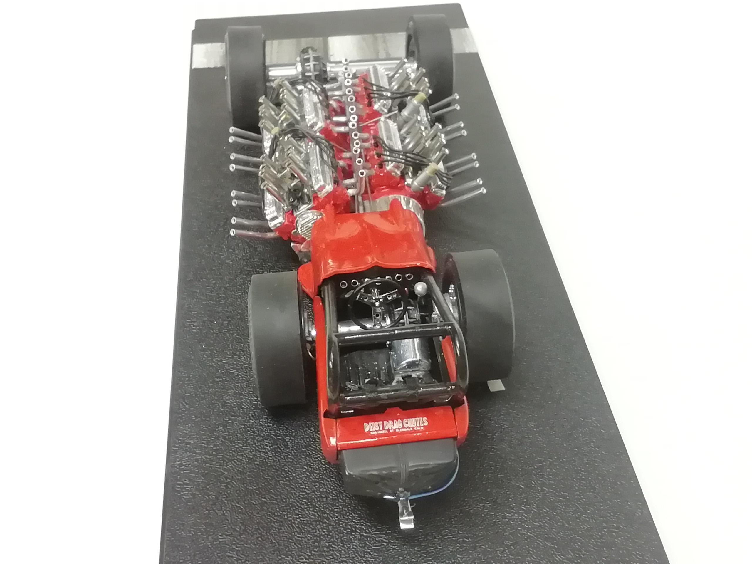
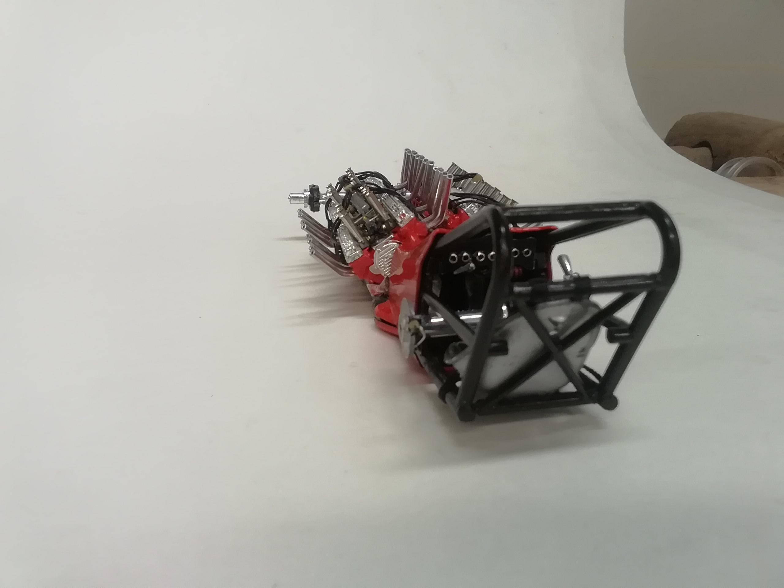
DONE!!! Thanks to all for looking in during the build! I got a lot of enjoyment out of this kit. It's not 100% accurate by anyone's standards, just a few details where I thought I had skill enough to add them. Only a couple or three pics here, I'll post a few more in a separate thread. Incidentally, I have pertinent photos and descriptions on how I did the fuel delivery system. I'd also post a thread on that if there was any interest. Comments and observations welcome

-
Thanks for the shout outs you two! Just did a re-coat on the cowl piece. I'll give it a day or two to cure. Shouldn't be too long to finish the build.
-
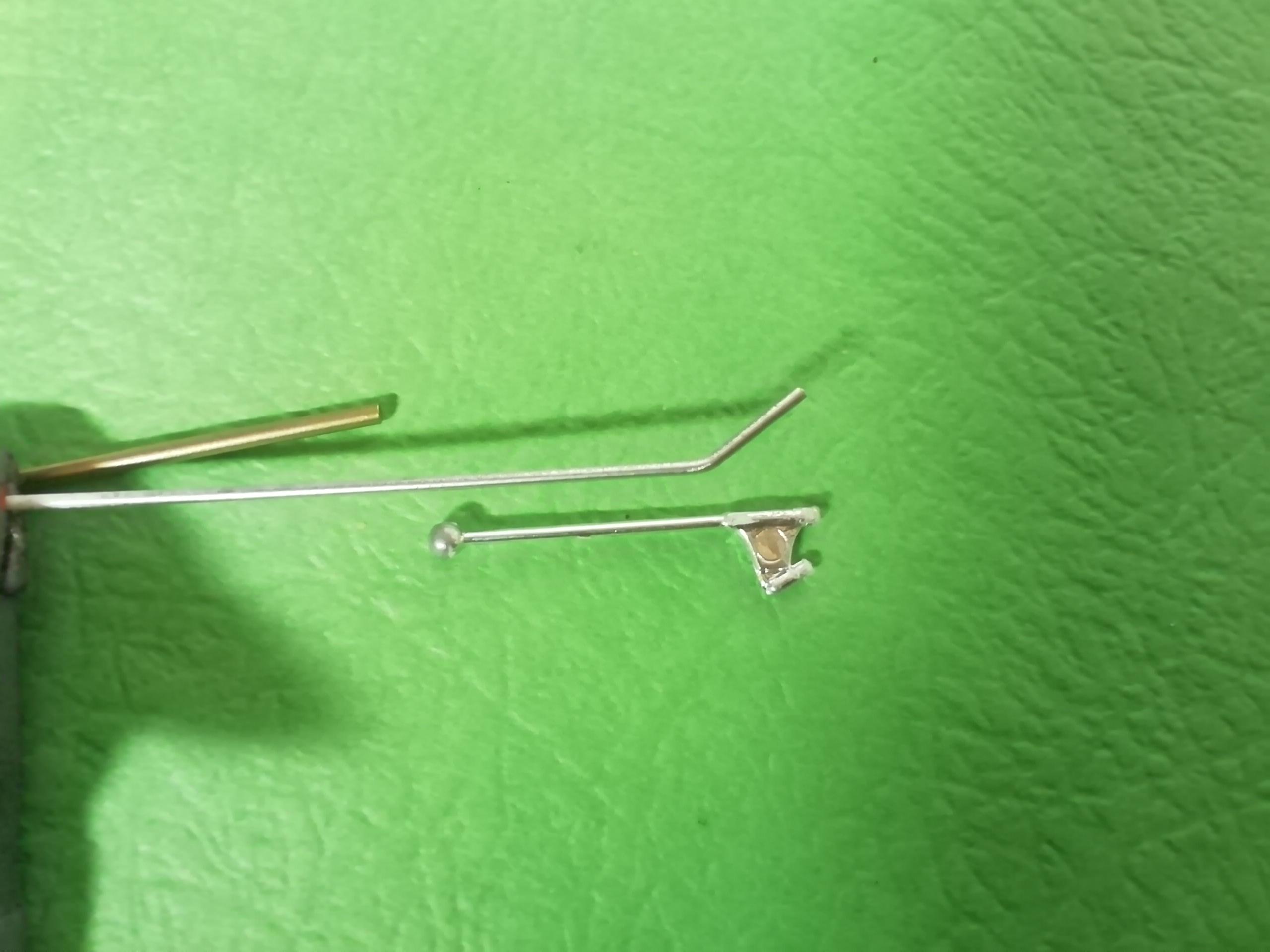
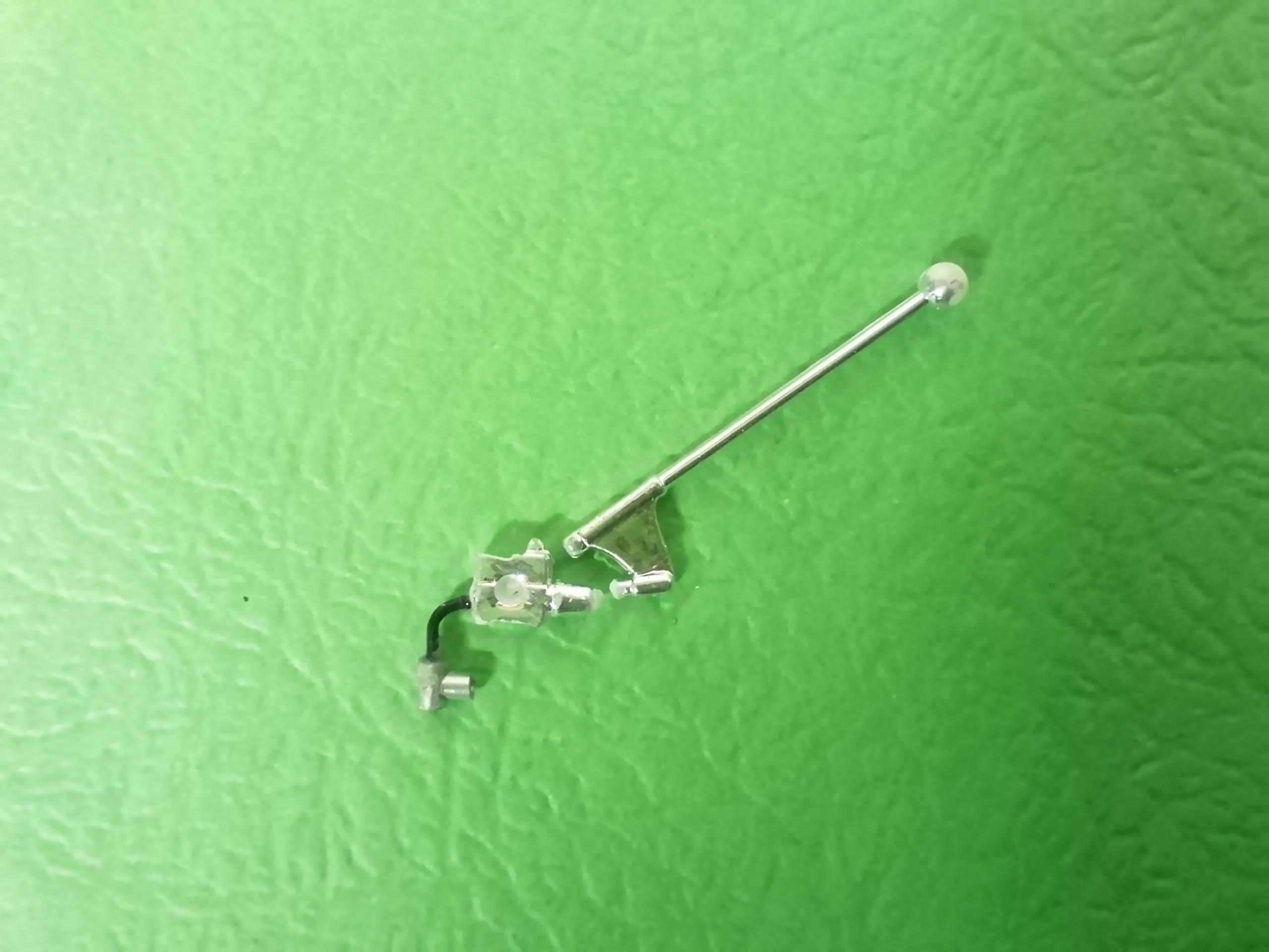
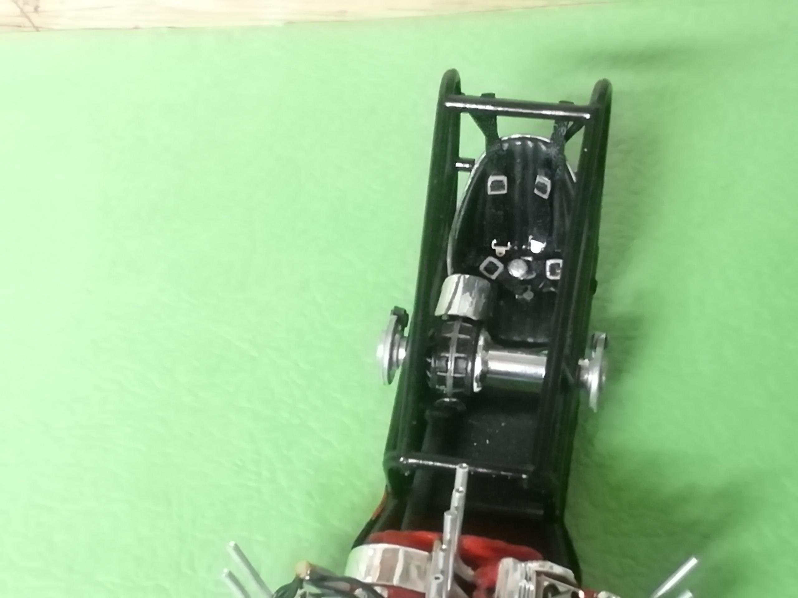
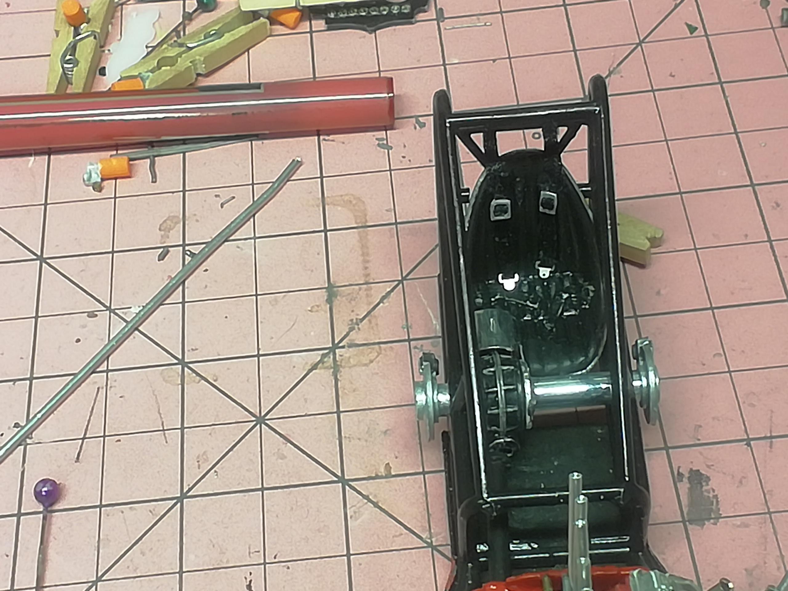
The kit supplied dash has a slot on the right side allowing the brake arm to fit properly. This slot didn't exist on the real thing, and, after rebuilding the dash I intentionally covered it over. Short version; I substituted a piece of rod for the kit part. The bend is how far the arm had to travel behind the dash to reach the cylinder. After the install I cut the vertical part of it to approximate length, snipped the ball off the kit part and remounted it on the new piece. The steering wheel had blobby spokes and lightening holes in it. I filled the holes to get the solid look, not happy. I found an identical wheel with lightening holes in the spokes in much much better shape in the parts box and used it. Happy. Comments and observations welcome.
-
This is the mockup. While the clutch lever and magneto kill switches are attached to the dash, the dash is only in the car for the shot The clutch lever is made from my good friend Mr Solder. I was going to use aluminum but I felt it was just too thin And the kill switches A little touching up then it's the brake lever and steering wheel. Comments and observations welcome.
-
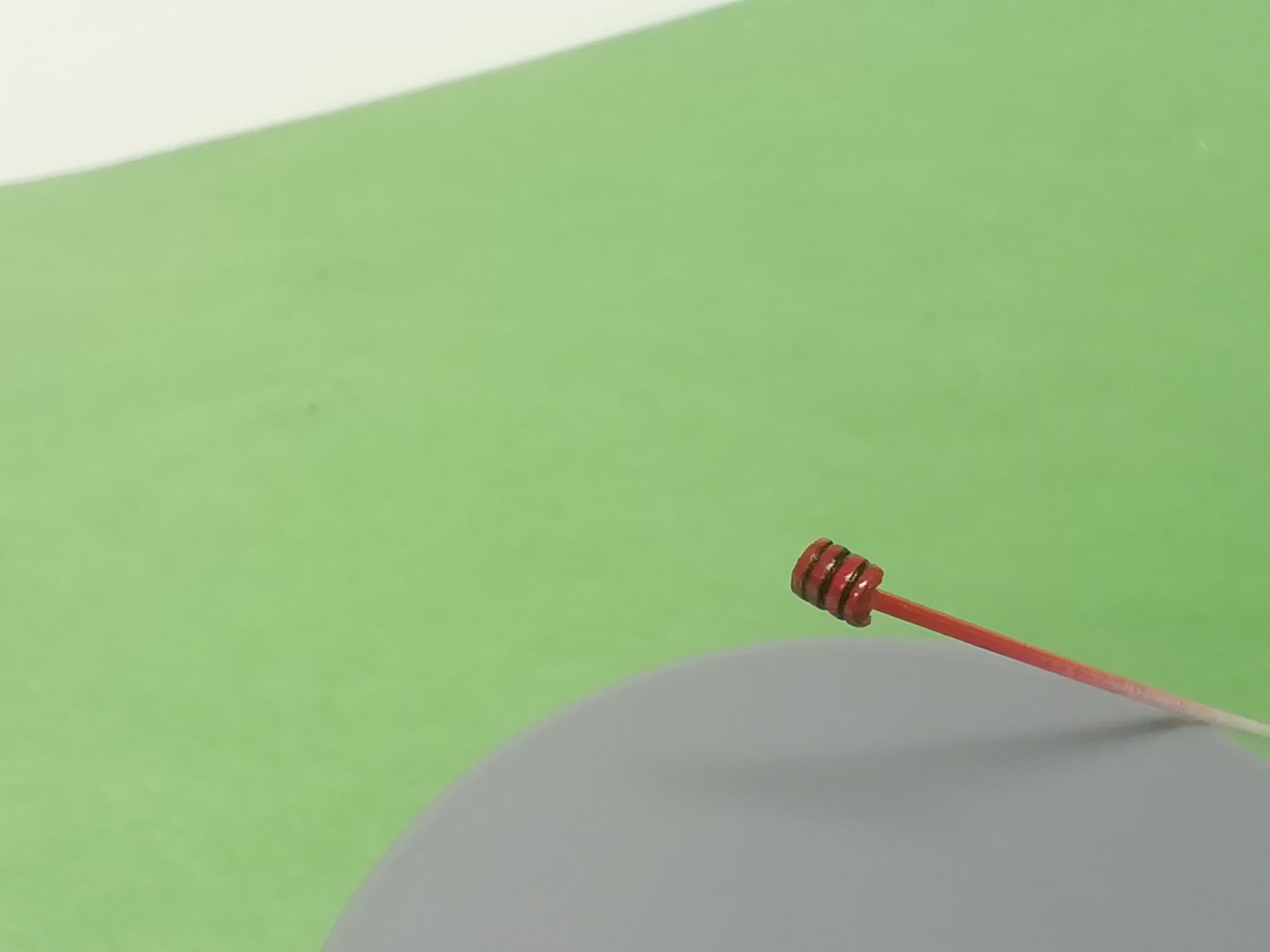
Another item not included in the kit are the magneto kill switches. These are located attached on the lower right side of the dash, mounted to a separate metal panel. There were 4 of them, one per magneto, removed from a junked WW2 aircraft. Everyone's seen these in movies, lift the red cover and press the button, but I'm not sure if these ones were just covers or the actual switch. I made mine in one piece from styrene tubing, making the separator lines in a tube cutter, then cutting the tube in half lengthwise. The unit was painted red and given a black wash. For the record, the black lines are not near as thick as they appear in the photo. Comments and observations welcome
-
Wow Billy, nice to meet ya! Glad you like the build! If you have shots you can send them here, I'd love to see 'em! I'm doing my best to interpret the car in 1/25 by adding a few xtra detailing touches, and I thought there would be a few modelers on this site who would enjoy seeing someone attempt this much-maligned kit lol. I did write Ken Foran (he did a brass scratch build of this car) a text concerning the fuel system and he was kind enough to post an abbreviated diagram by Mr Dyda himself for me. I'm thinking of posting the engine builds as a separate thread if there's any interest. Thanks for the shout out!
-
Thank you guys, 'preciate the comments.
-
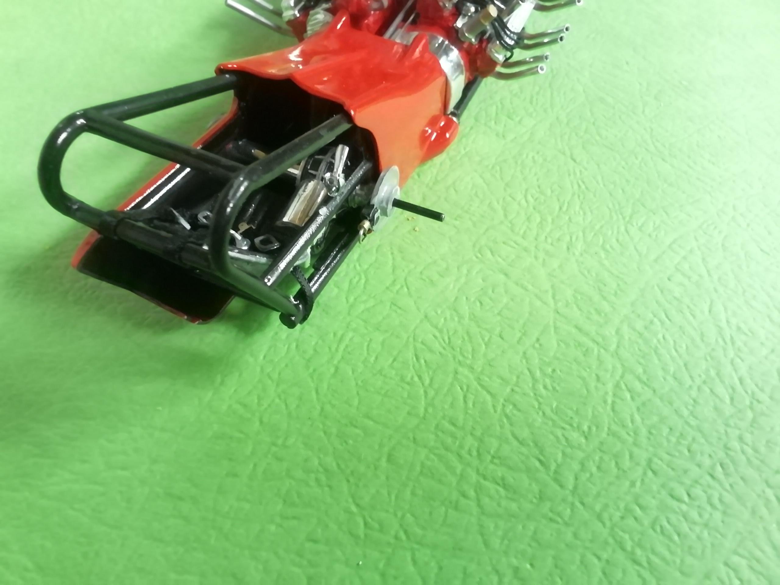
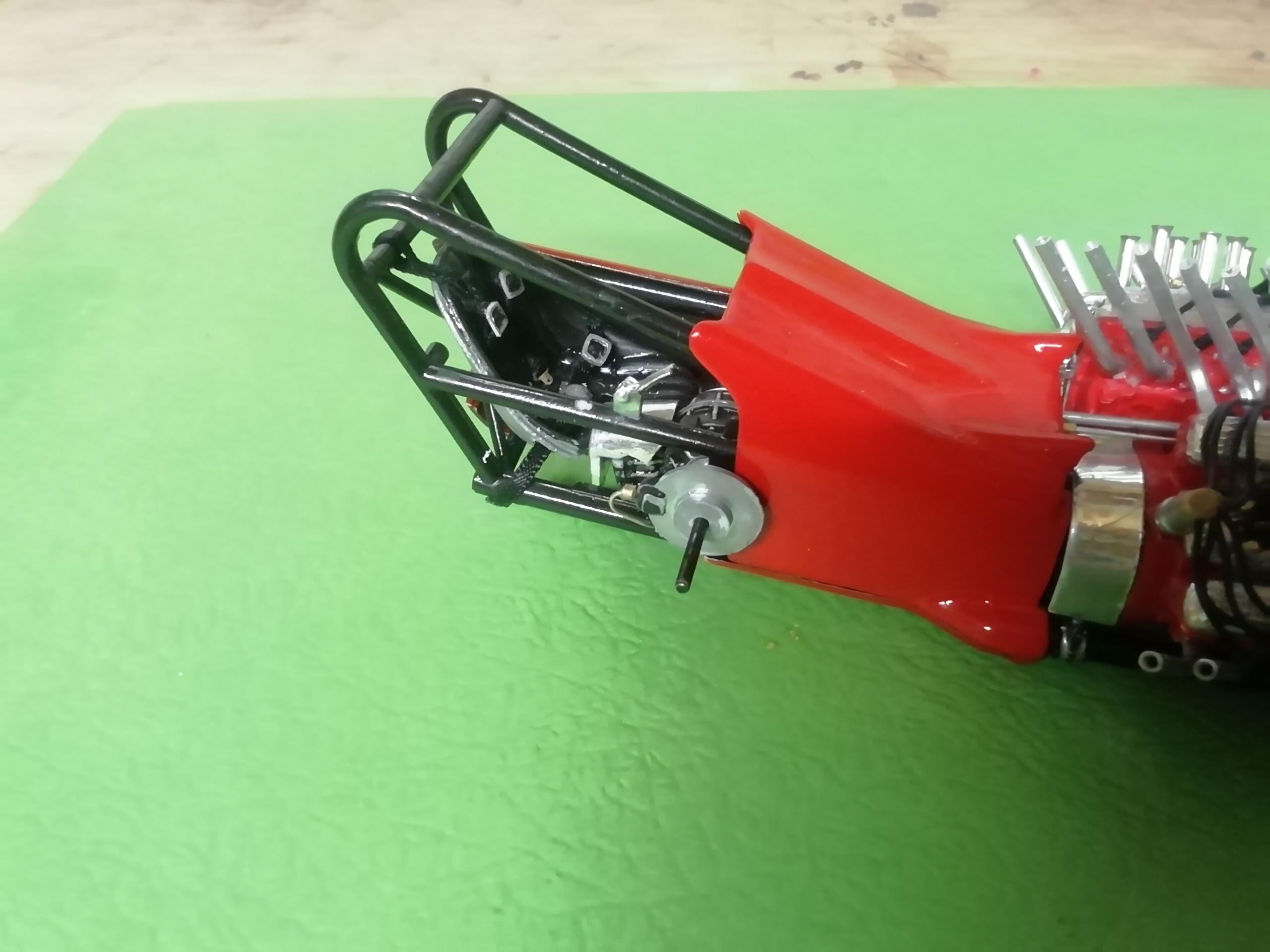
And here is the cockpit part of the chute release with cable entering the frame and side body panel finished to fit around the assembly. Comments and observations welcome
-
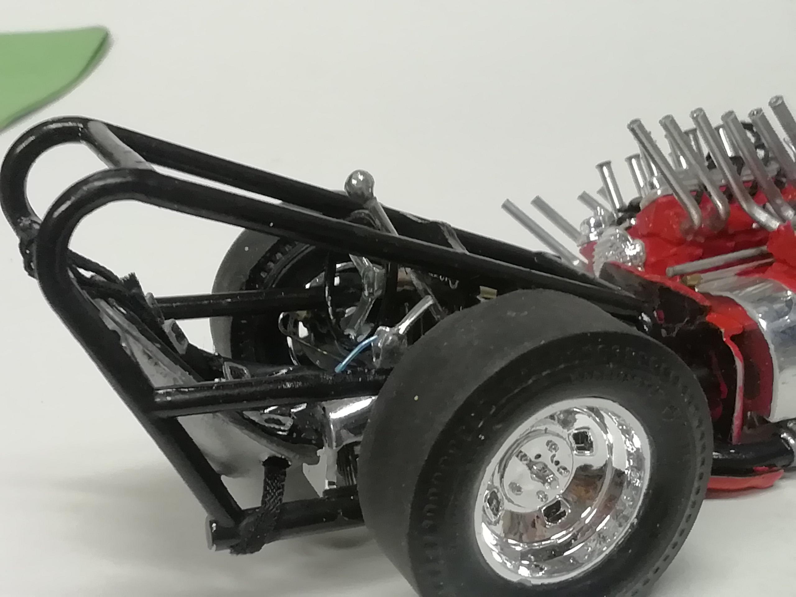
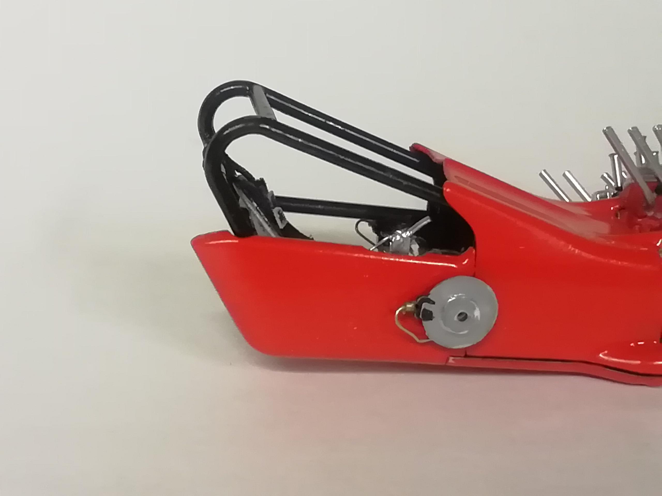
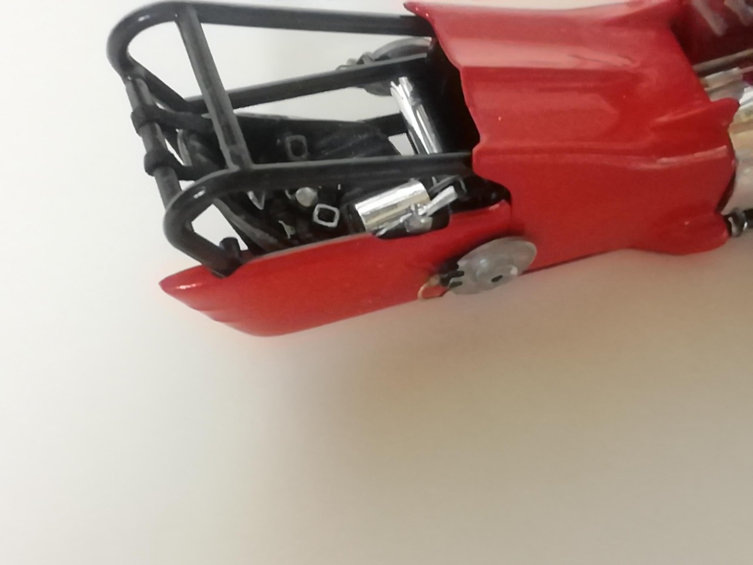
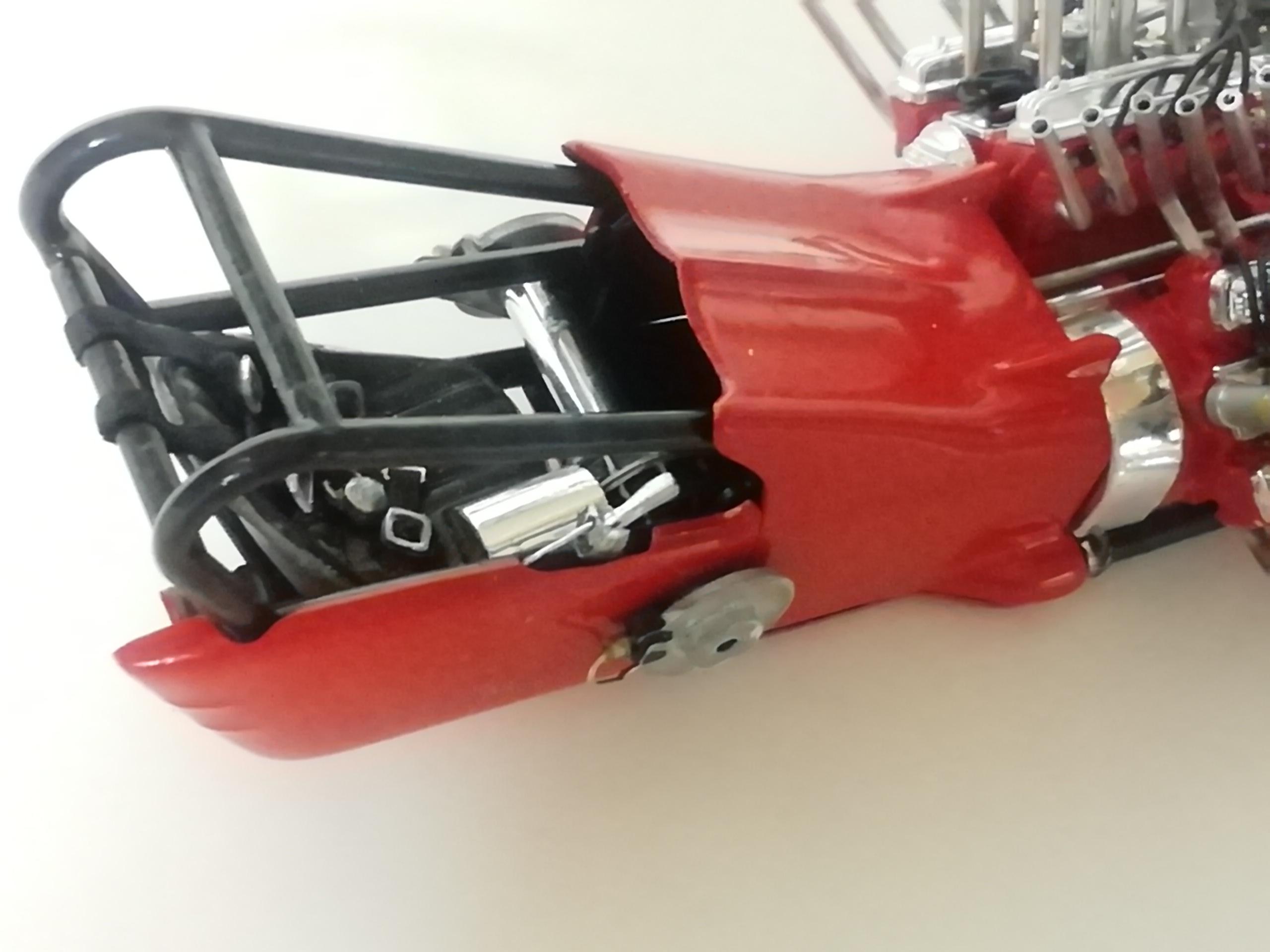
Parachute lever. The kit has this mounted inside the frame but on the real car it's mounted on top of the rail with the actual cable disappearing inside of the rail itself. I replaced the blob of kit chrome with a blob of my own lol. I filed the seam from the lever as well as shortened it by about a 16th. The lever support I made from pop can aluminum bent to a u-shape and drilled 2 holes to cradle the bumps on either side of the lever The no-return point was filing a clearance 'wow' in the body panel like on the actual car to allow the lever assembly to sit in it's new location. I've drilled a shallow hole in the frame rail for the cable to sit in, and a hole in the lever pivot for the other end of the cable. A separate piece of wire will come out along the narrow side of the shute to complete the illusion. Obviously I haven't added the short section from lever to frame rail yet but this is the general look. Comments and observations welcome
-
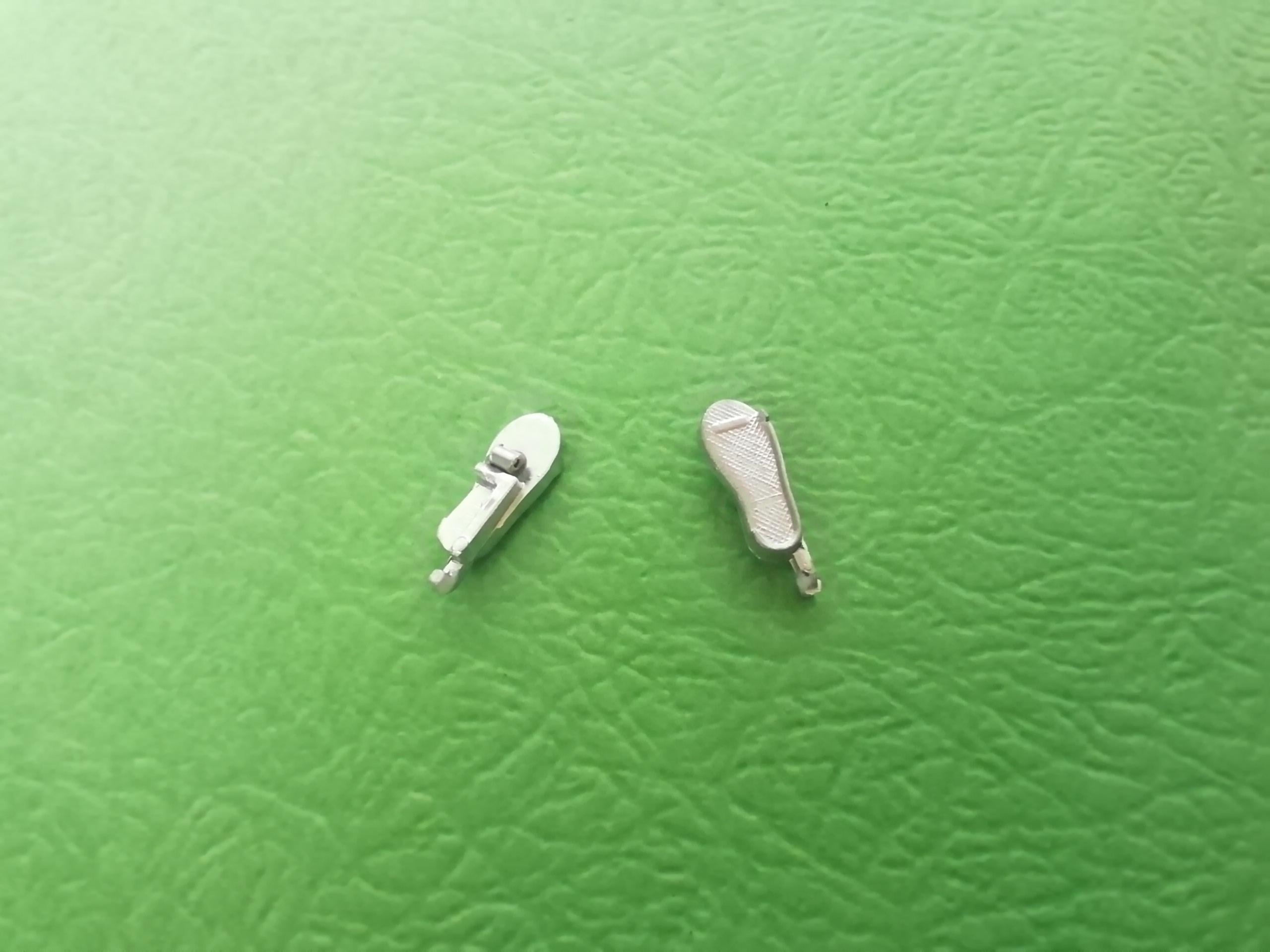
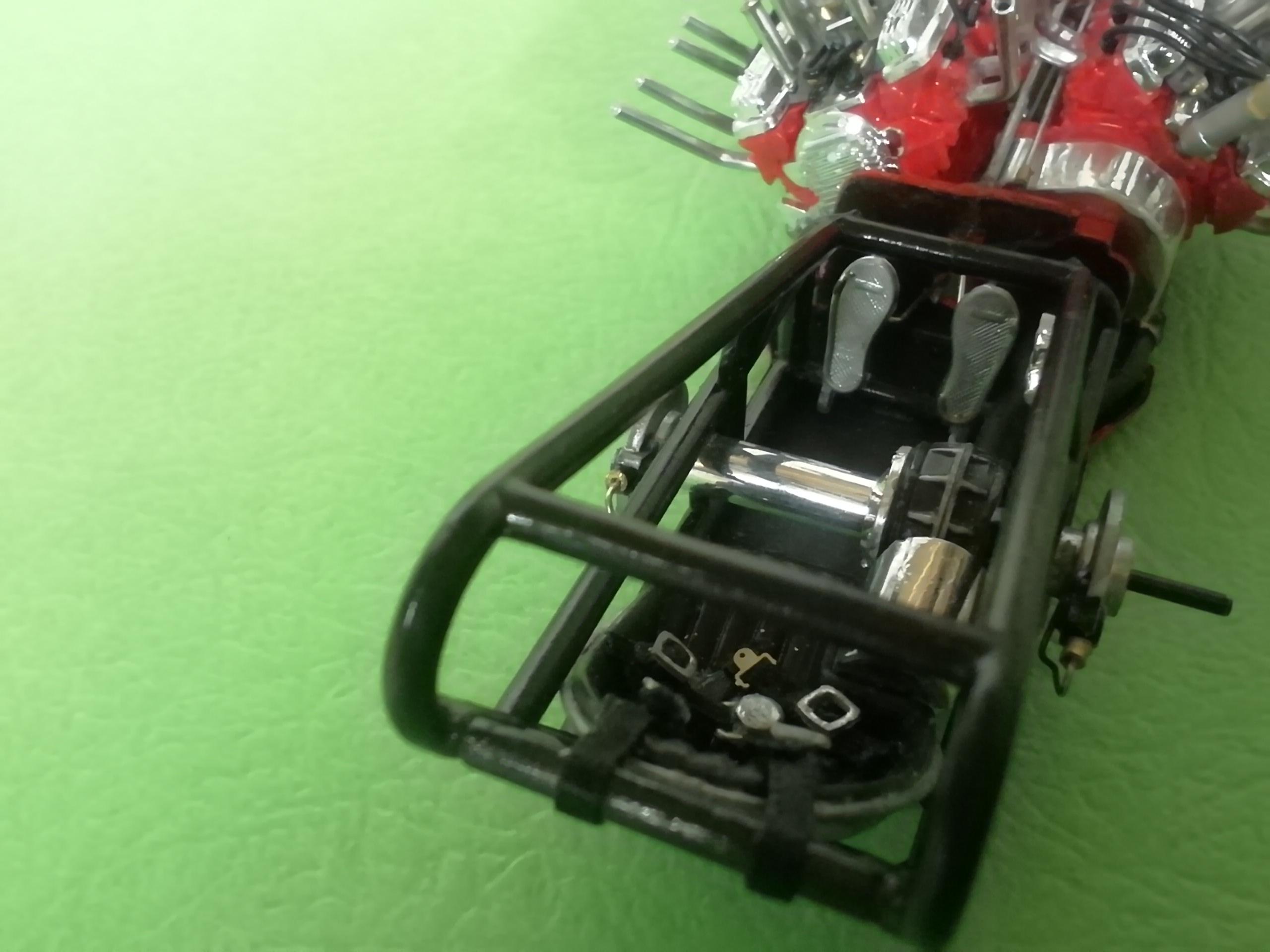
Clutch and gas pedals. The kit supplies these pedals connected as what looks to be a finished piece. This would explain what I read somewhere a couple of years ago that the car had two gas pedals and the pilot used both feet at once to roar on down the strip. Must have been someone who had the kit and took the piece at face value. . No, they should be separate clutch/gas pedals as below. Note they have 'hooks' that (supposedly) attach to thin rectangular sections that are molded in to the frame. Paint the extensions black and they won't stand out. This is another "why even bother?...." detail. A short piece of aluminum tube has been cemented to the back of each pedal to hold the linkage from pedal to firewall. I made sure the gas pedal is closer to center. It was slightly askew in this shot but has been corrected. The pedals chew up a lot of visibility in the cockpit, and when you add the dash the view's pretty well blocked off. Just a few firewall blemishes to touch up anyway. And a couple of views of the pedals and linkage. Apologies for the slight blurr. Also, you may notice a rough edge to the top of the firewall. I had gotten ahead of myself early in the build and had to Hulk it apart before the model tube cement had fully cured. It isn't visible as it sits under the edge of the cowling and fits perfectly to the mating unseen scar on the underside. Comments and observations welcome.
-
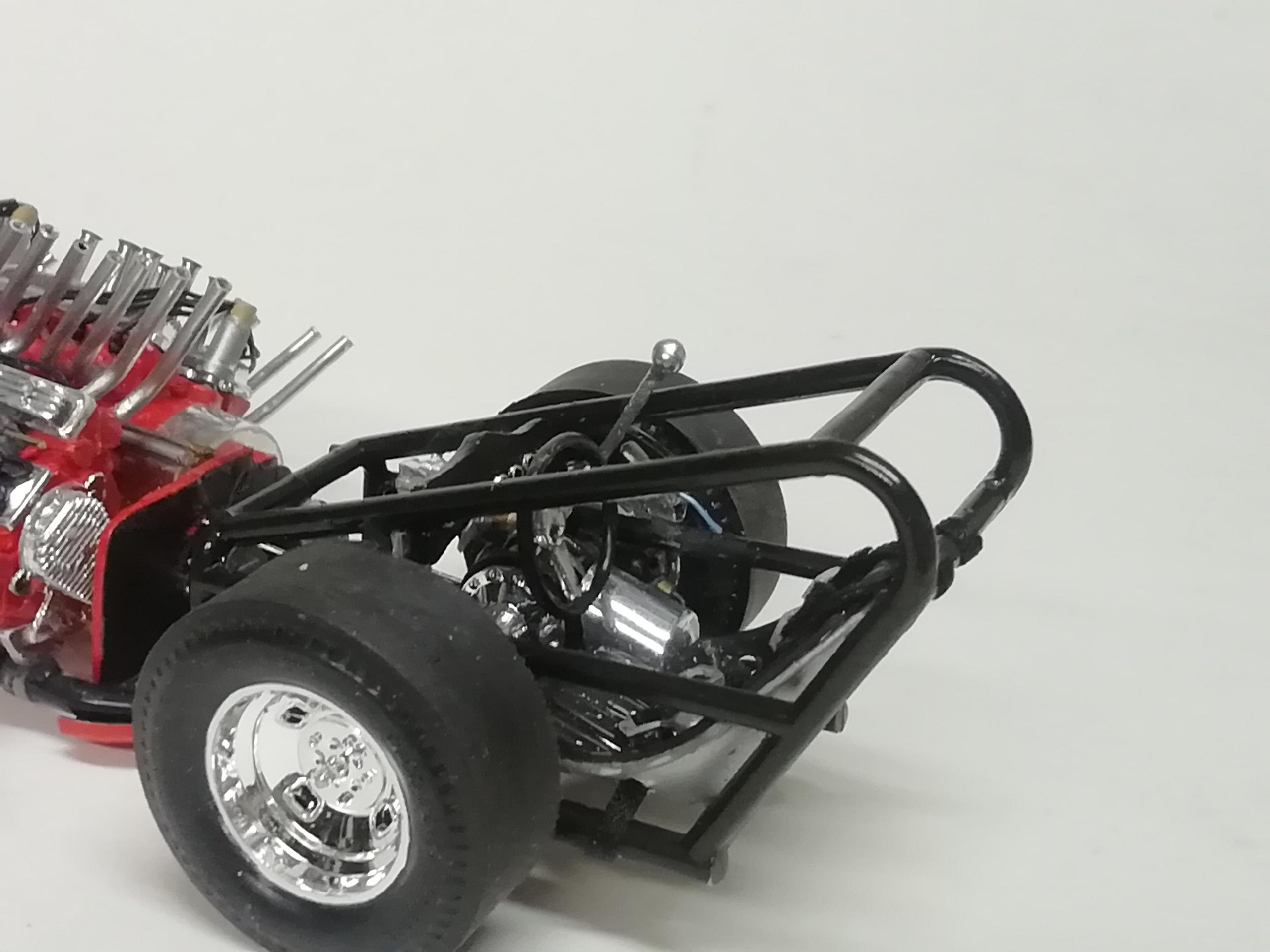
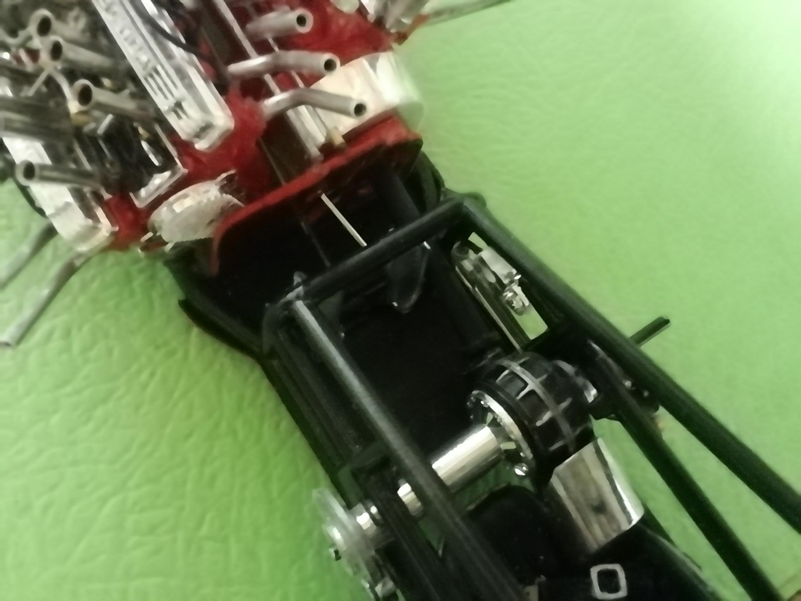
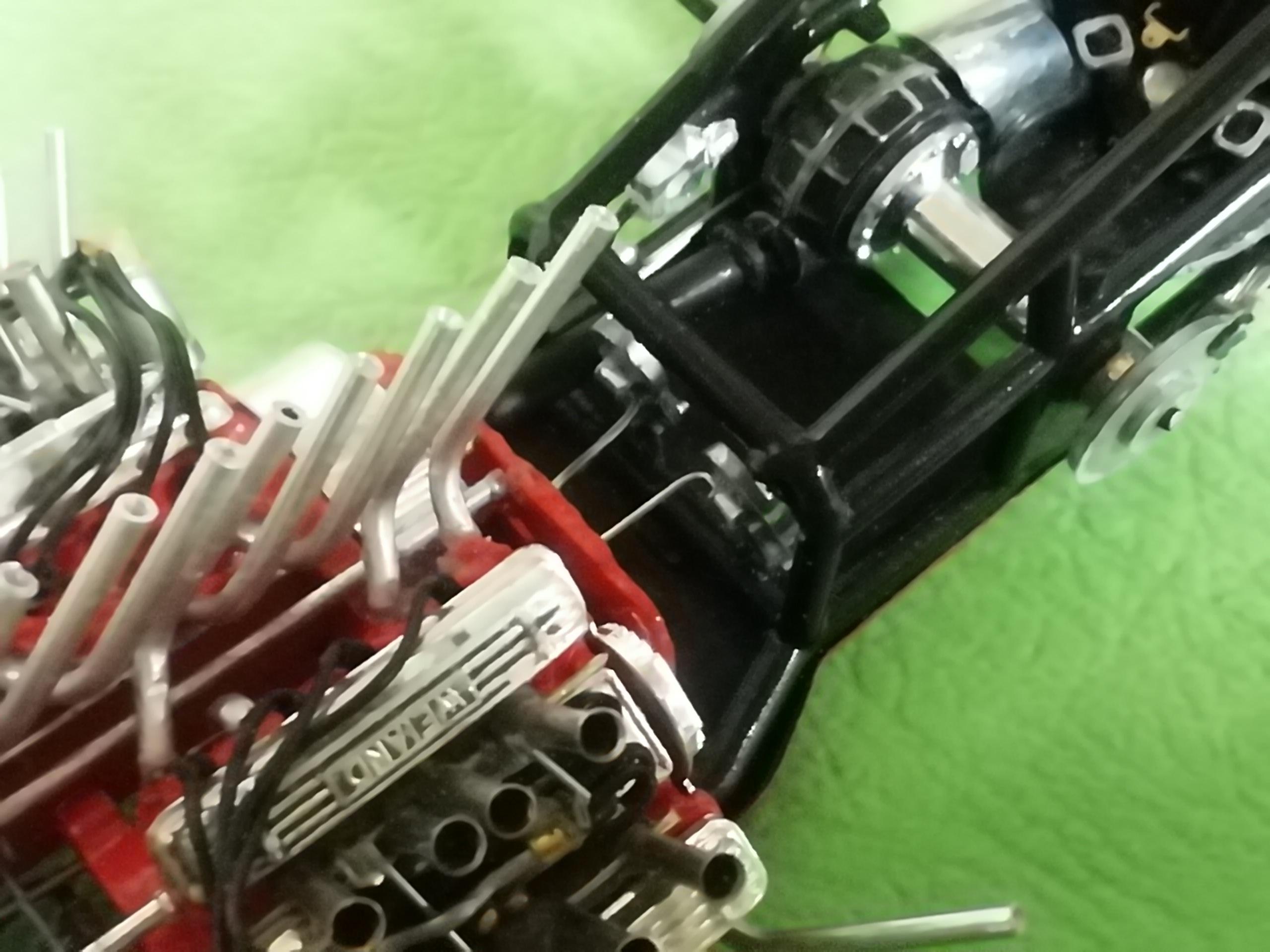
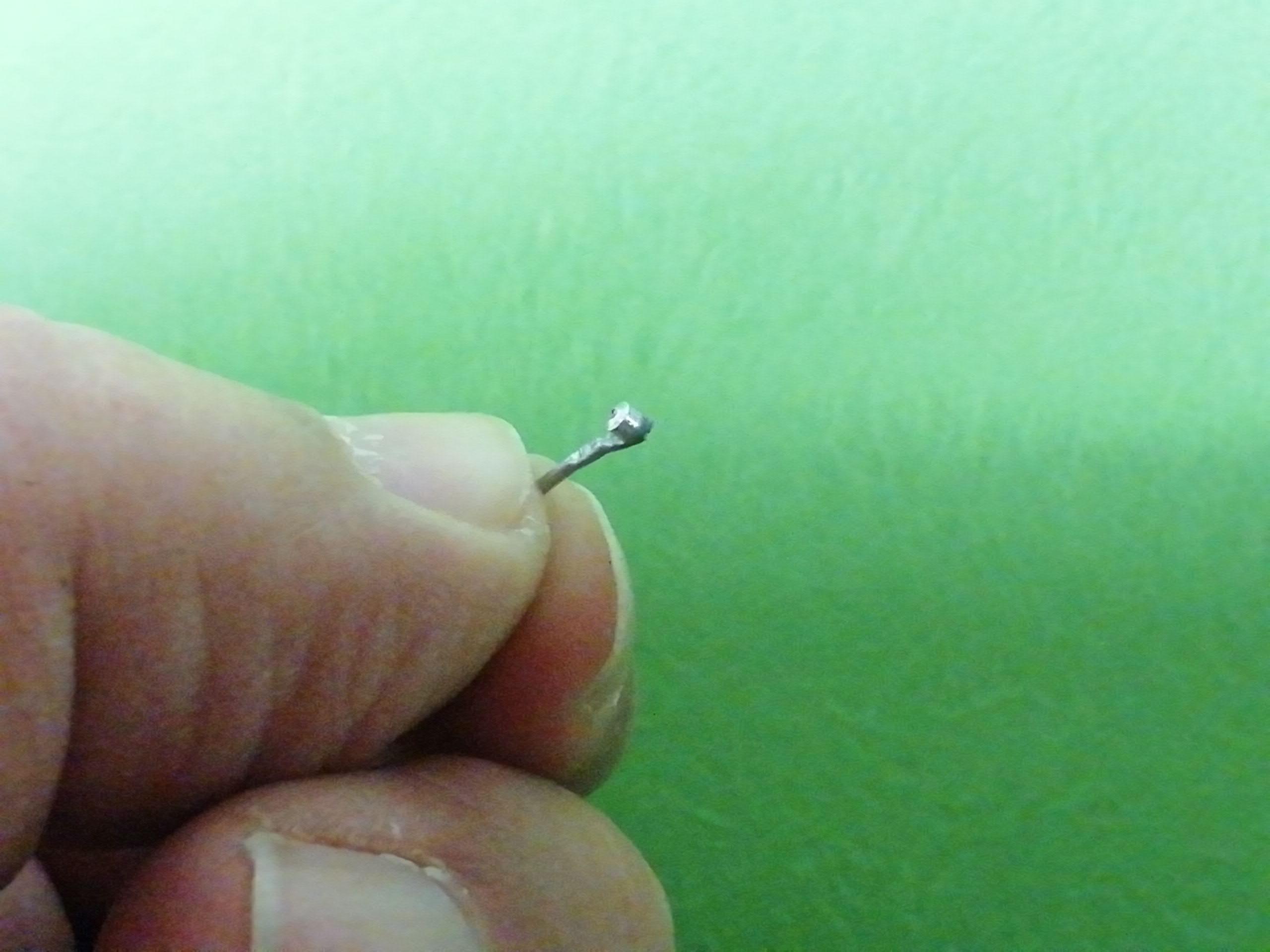
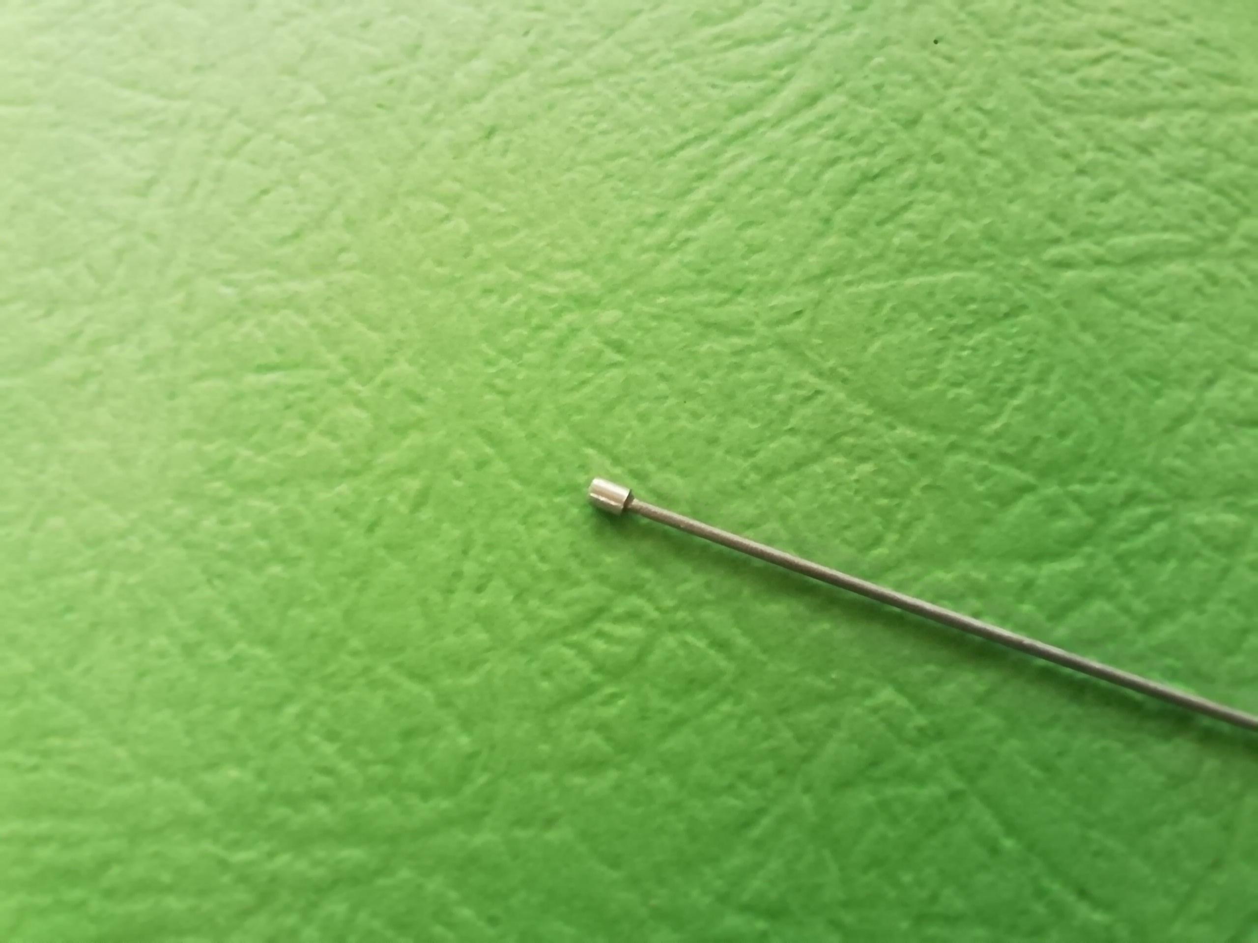
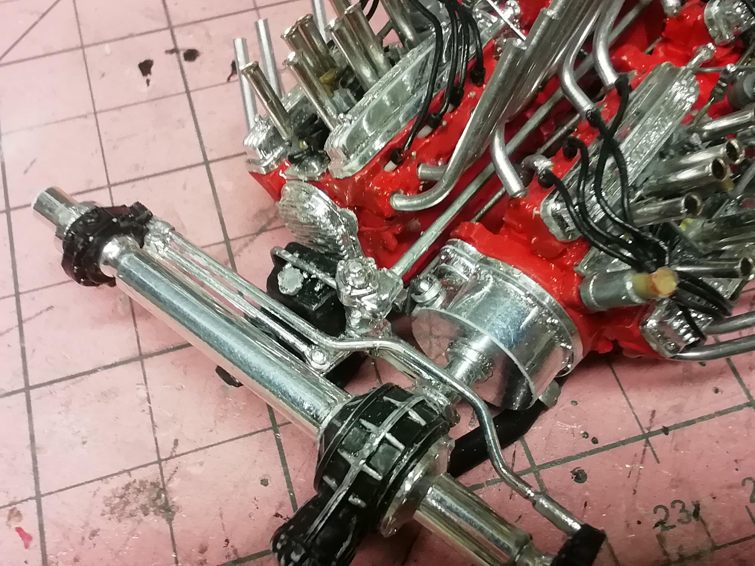
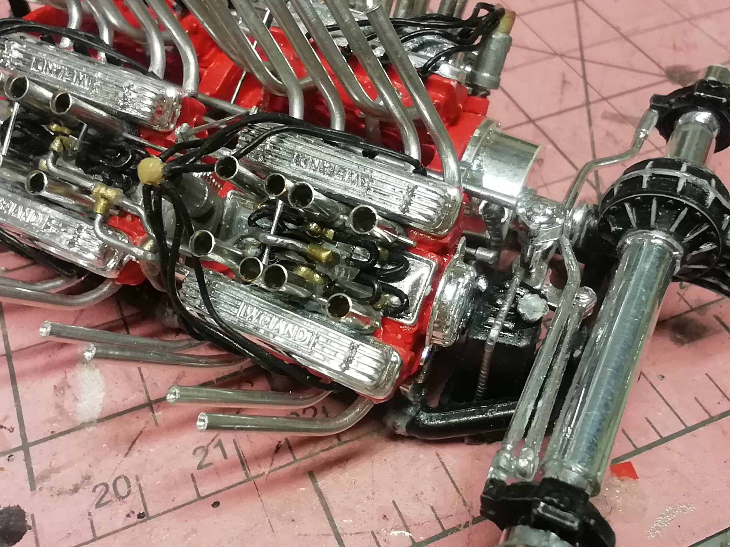
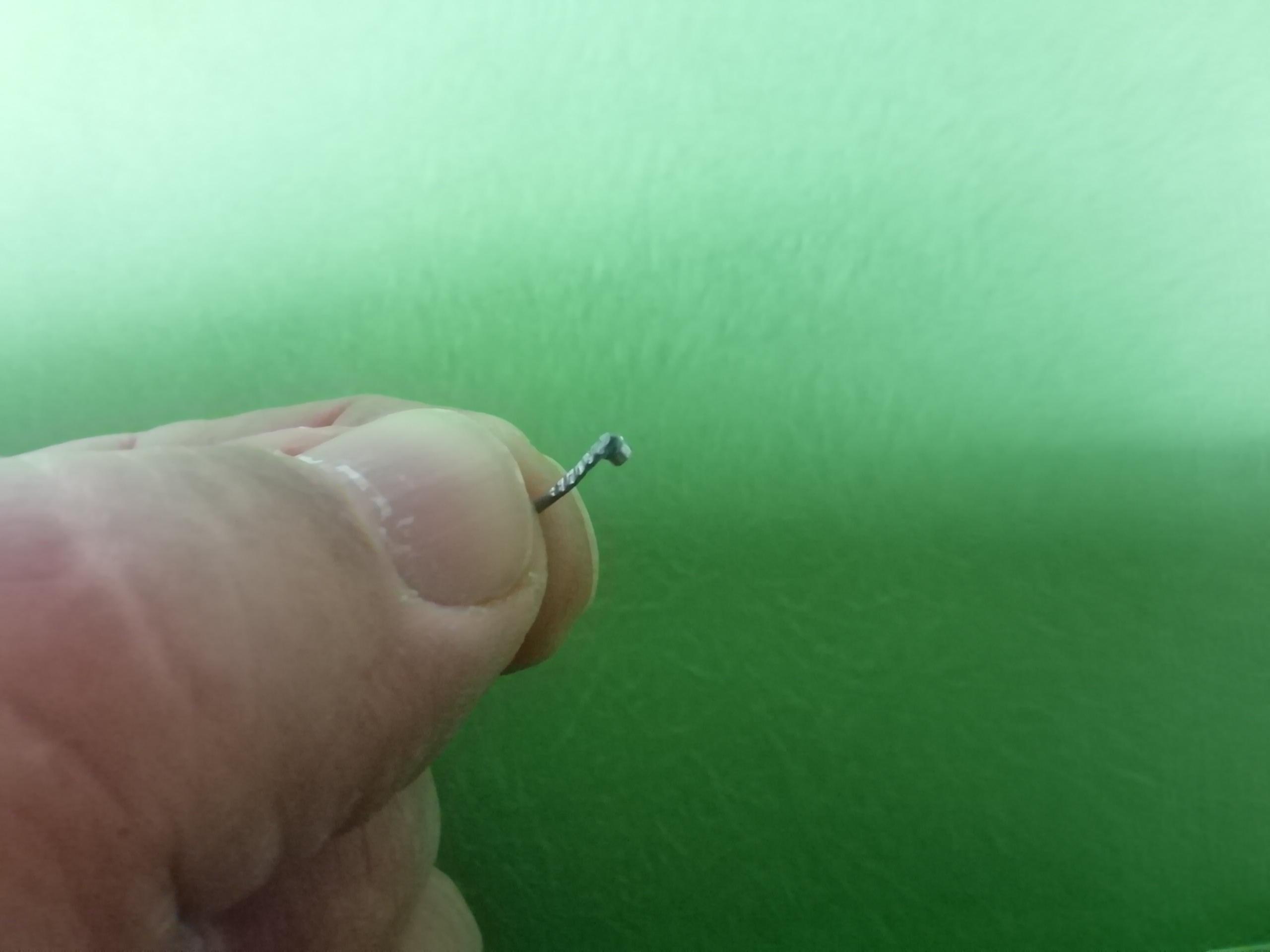
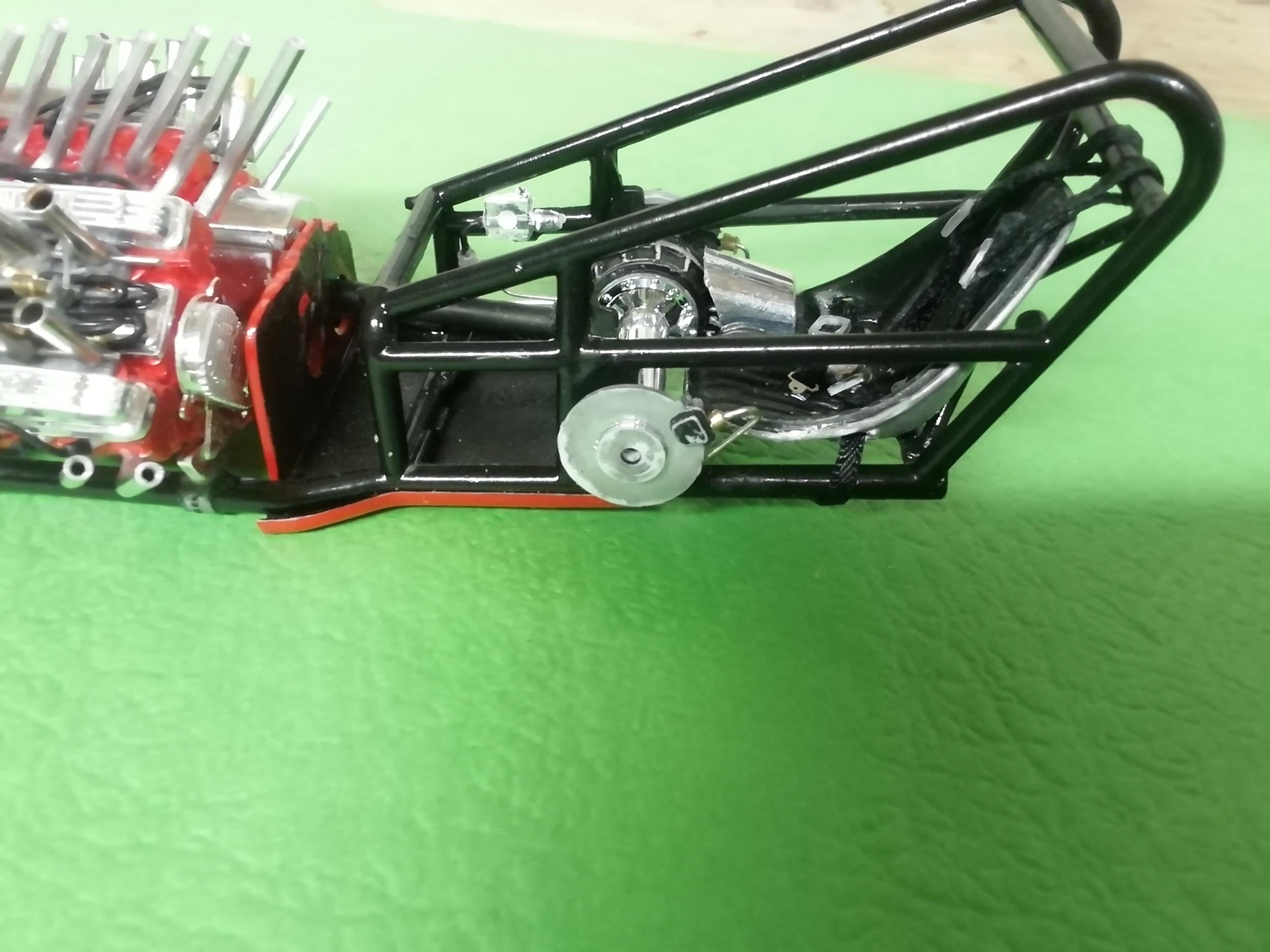
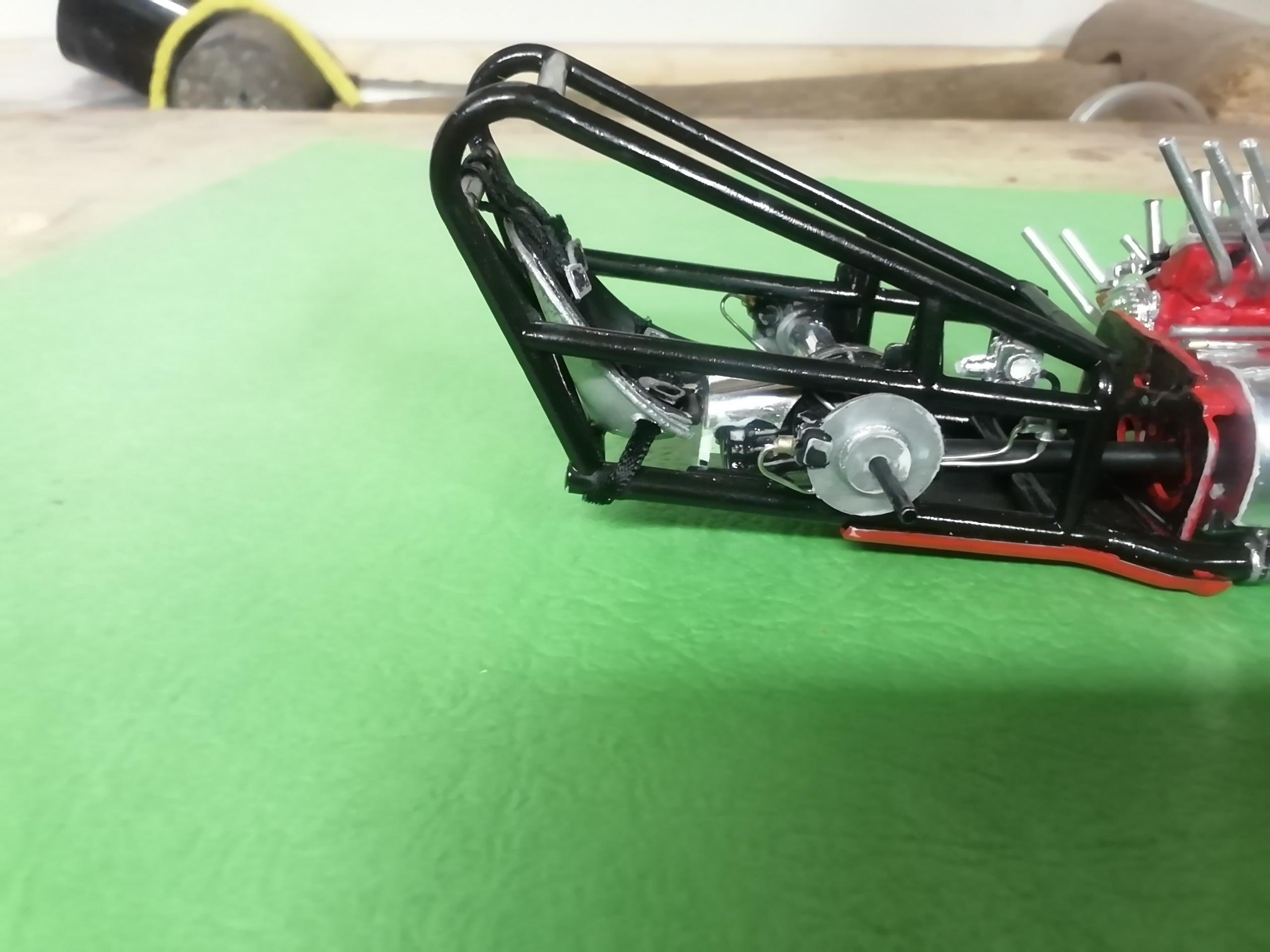
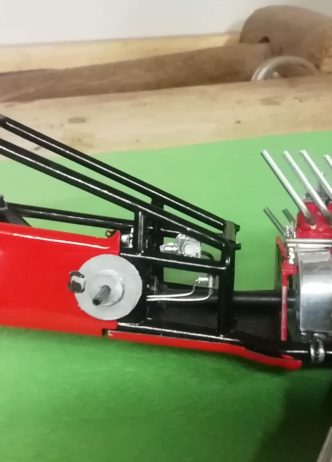
Clutch linkage was something I thought about during the build but didn't get around to till now. Believe me it would have been a whole lot easier after the first bank of engines were installed and there was room to work. But anyway.... The linkage arm was easily made with a small piece of aluminum tube cemented to a piece of flattened small diameter solder. This will be attached to the side of the front bell housing. I painted a small diameter length of styrene rod silver. I also made sure it wasn't the same diameter as anything else in the area. A slightly larger id piece of aluminum tube was slid over the end acting as the pivot arm attachment. The rod was inserted from the front above the axle till it reached the firewall. It took a few tries till I got it to install between the engine banks in a straight line. It does however have a slow rise from the firewall to it's location on the linkage arm up front. At this point rather than just have the arm simply glued to the bell housing I sliced a narrow piece of aluminum tube, cut it open into a horse shoe configuration and used it to cover the glue joint. Worked out ok I think. Hard to make out in the photos but it's there. Comments and observations welcome.
-
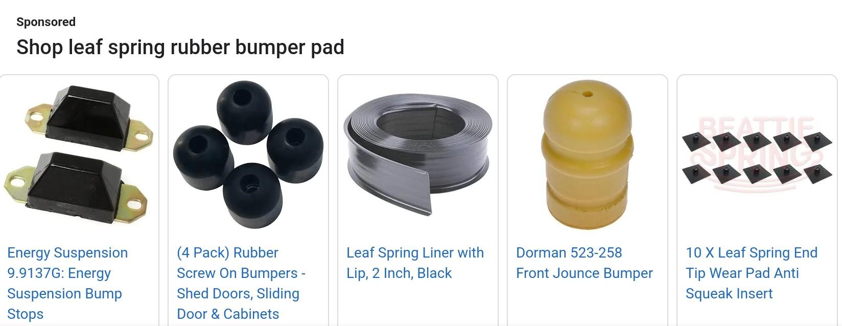
Found these examples of leaf spring bumpers and protectors on Amazon. Not a big deal to modify to suit the application, and you can bet it's a small understated detail not everyone thinks of. I think the simple 'puck' style works well in scale.
-
Guess I was a bit vague. On your leaf spring, what do the 4 round pieces of rod represent. I recall puck-like rubber spacers (looking somewhat like those) on the axles and the backs of some leaf assemblies back in the day. Kept metal from hitting metal due to bad potholes, rr crossings, etc. I thought your leaf spring was under a frame cross member and that would explain their (more for looks) function. Whatever, they're a nice detail.
-
Clean work like you're doing turns a kit into a looker every time, Joe. Are those bumper pads on the front leaf? Nice quiet detail touch! If they're not, well, I'm old lol. All kidding aside, I'll be adding pucks like that to my next cross leaf build. Wel done!
-
...and the external lines left right. They are weensy, but it's another texture that catches the eye instead of the empty tire/axle/body fit on so many fed and open wheel drag car models. Make sure if you do this to test fit the wheel/tire and side panels before things solidify so your line doesn't give you problems, as well, gel ca is great for this. Comments and observations welcome
-
Thanks guys. Looking for time to do the outer brake lines between the wheel caliper and body. Should have them done soon I hope.
-
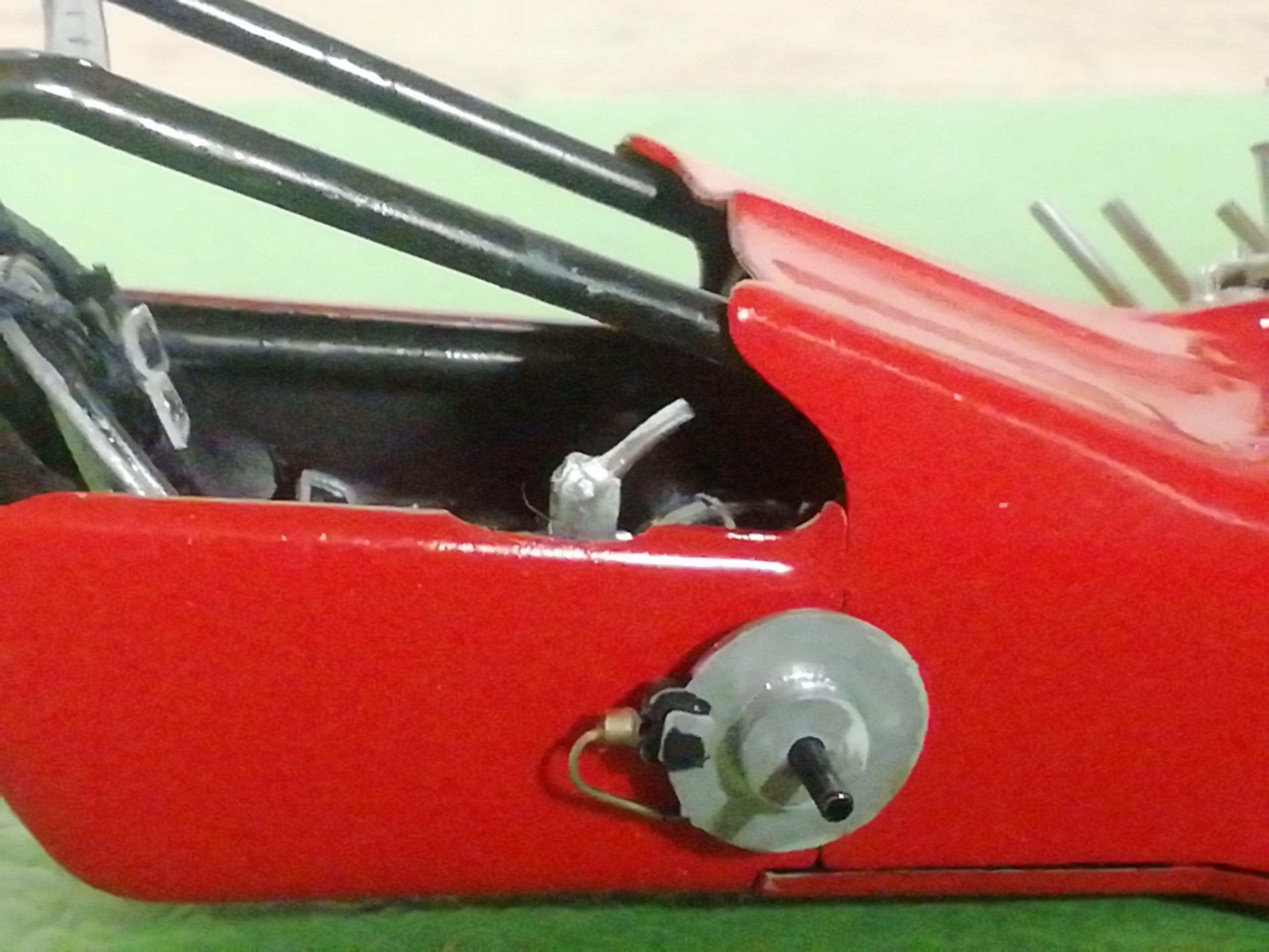
And here's the brake cylinder and the two brake lines mounted. Once the cowl is mounted this will probably not be seen, just chalk it up to practice for the next model where it will. Comments and observations welcome.
-
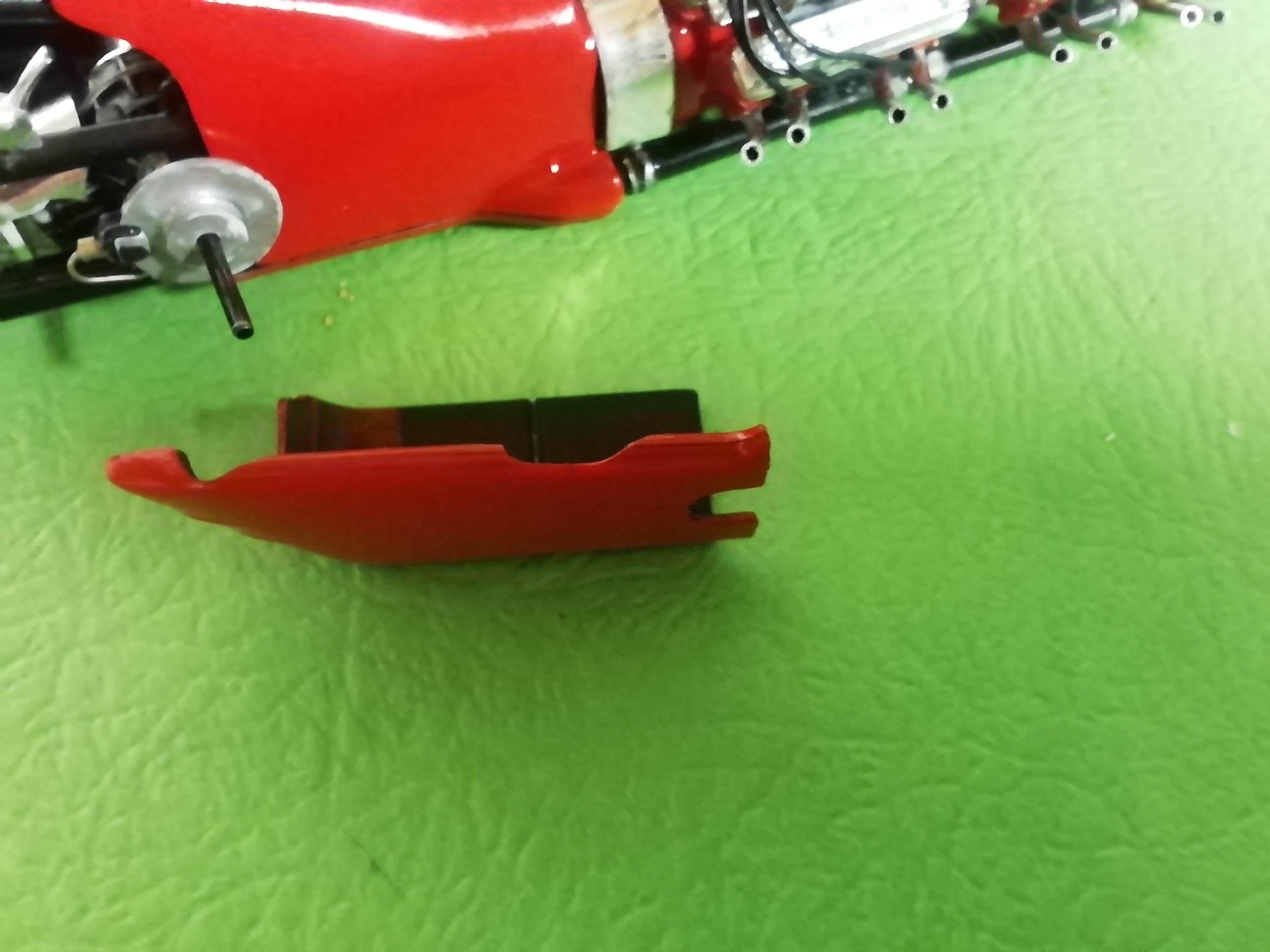
Brakes. The usual hand operated rear-brakes-only setup is on this car. The kit has a one piece lever and brake cylinder. I separated the lever/cylinder in to two parts to install the lever after the dash and cowl pieces are installed. Makes the cylinder easier to work with. In the mock-up I've added a 90 degree line with a tee on the end. The horizontal outlet connects brake line to right wheel, the vertical one lets the line go down to cross along the axle to the left wheel. Odds are this detail will probably never be seen but so what. Comments and observations welcome.
-
On to the brakes. Pretty simple but for a few bends to make and a little filing to the rear side body panels to allow the lines into the cockpit. However, I did have a couple of issues with the rear axle and disc assemblies. Issue #1: Built with no mods, the rear right side axle piece stuck out noticeably farther than the left. I carefully removed enough from that piece to have the discs sit equidistant on both sides like the 1:1. Issue #2: Quite by accident I noticed the backing ring (it fits over the end of the axle) of one disc is deeper than the other. Not enough to correct anything to do with the axle discrepancy, just odd. I made sure to use the deeper one for the axle I had altered. After these things were done, the metal insert axle was shortened to suit. The front assembly built up without a hitch Comments and observations welcome
-
Thanks Marcos, so far so good.
-
Thanks Joe, glad you're liking the build.
-
And here are the 4 belts with associated accoutrements including a homemade central buckle/release all cleaned up and installed Comments and observations welcome
-
Got the seat back belts done to see how they look on the model. Lap belts are next Comments and observations welcome.
-
'Preciate the shout-out sflam. Got a couple of the belt adjusters finished and filed to a thinner aspect, they look pretty good imho. And, I must admit the pipes turned out better than expected. Like a lot of the mods they're not 100% accurate but I do think they convey the personality of the car.
-
Joe, thanks for the walk thru. I may use it on my next build. Many thanks for the kind words Scott. The finish line is getting closer.