Farmboy
-
Posts
518 -
Joined
-
Last visited
Content Type
Profiles
Forums
Events
Gallery
Everything posted by Farmboy
-
Wow Dan, thanks much! That's a heck of a kudo. Dunno about the prize-winning part but it is unique. Just time consuming small stuff to the end now. 'preciate the shout out.
-
Hey Gary. Thanks for the suggestions, always appreciated.
-
So glad you're enjoying the build Scott! To boldly go...
-
Because of the spacer I made to move the blower forward, the two large air pipes also need to be lengthened. They were built to join to the manifold extensions with half lap joints, making it easier to simply add a short straight extension instead of rebuilding them entirely. You can see this joint in the top most pipe in the shot below. Got lucky in cementing the homemade extensions straight by slipping a section of plastic tube (coffee stir stick) over the joint to hold them in alignment while the tamya cement cured. A touch of scratch filler, a light sanding, some primer, followed by a coat of krylon chrome and they should be good to go. Comments and observations welcome.
-
Thanks for the kind words Gary. I'm constantly surprised myself at what I notice once a picture is posted...details like the two plug wires disconnected (corrected), and some smoothing to small areas missed (corrected) even though I have the actual unit on the bench! No secrets here lol!
-
It's starting to look a bit busier. The oil filler pipe has been installed and I've connected the fuel supply line to the f.i. rails, the other end of the fuel line going to a simplified barrel valve. I should have waited to install the upper rad hose first as it will go underneath the fuel line but I left room for it. Two other lines will connect to the side (or bottom) of this piece and then to the not yet installed fuel pump at the front of the blower. A better view of the barrelvalve assembly showing the throttle lever. This will be connected to a cable that disappears under the bed ending (in my world) at the gas pedal. Also installed the shaft/pulley to the generator. I notice the rear side of the cab opening looks a bit grotty in pics but I don't see it at the bench. Hmmm, see if I can fix that without too much trouble. And just so the left side doesn't get all the attention, I think the front end business will more or less balance once the intake pipes and rad hoses get installed. Note the little hole for the fuel pump. Comments and observations welcome
-
Yessir. Looking forward to it.
-
Most of the upper fuel done The lines are good ol' thin gauge solder, tees are made from brass tube. The line going from the rear tee is an overflow line heading back to the fuel tank. A fuel feed will connect to the front tee from a barrel valve with its own fuel return line. A bit of overkill but the rear looked lonely. Note the rear connector line contours around what will be the oil filler. I'm off center so the bend looks out of line but it isn't. The white piece on the side of the block is the generator. Needs a pulley and paint. Comments and observations welcome.
-
Hey Gary, like you, that's the stuff I learned to model with. To some degree, old school is a major part of my modeling skills catalogue, and I tend to work with what I have or can adapt to be a believable part of the subject. Suggestions are always welcome.
-
The fuel injection rails were a bit of a pain... I had originally decided on a very small styrene rectangle with half round on the top. When installed, well, they looked like barn doors ready to taxi down the strip. Besides, the fuel line would have been the approximate size of the rad hoses. Not good. I experimented with aluminum, copper, and brass tube. None small enough. Then, I found a cello package of thin small diameter metal tubing in an overcrowded parts drawer the other day. Decision made. Still not decided on an injector harness. I made sure each tube will have a fuel line that clears the two rad hose fixtures so they meet each other at a tee. I like the off-brass color as it adds a bit of an accent to the predominantly silver/black motif in that area, but I may change my mind. A light scrubbing with steel wool should bring the shine down if I don't change it. Guess it's on to fuel lines, fan belt and air delivery. Comments and observations welcome
-
My pleasure, Super. This is a great site for new ideas.
-
Thanks for the kind words Gary, glad you're enjoying the build.
-
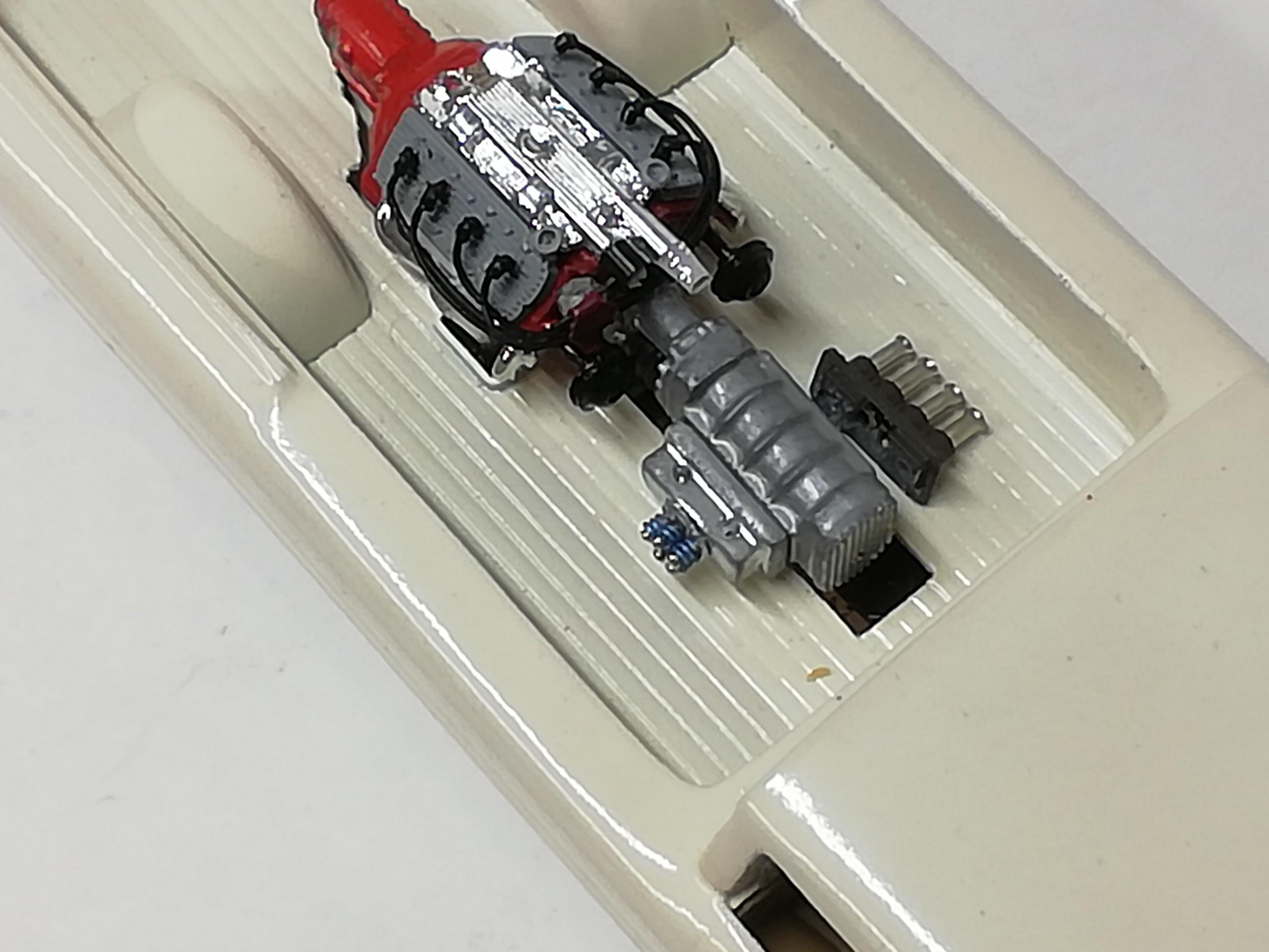
For fuel works I was planning on a central block with 8 lines total going to the manifold. The plumbing was so small and short I stopped at 4 and did a rethink for fuel delivery. The mockup shot below represents 8 injectors mounted on the manifold. Small styrene rod was sprayed black (hence the licorice alsort appearance). They will be sanded to an even height. Incidentally, the manifold was chrome, I sprayed it with flat clear, I'm ok with the finish. The fuel delivery bars were made from rectangular rod with a piece of half round on one side. These will sit on top of the injectors. I may or may not add simple wiring to simulate injector electrics. The bars will be sprayed chrome. A mockup of how things will sit on the engine, with room to plumb the bars despite the upper rad hose locations. I made those from aluminum tube to keep things a little more compact. To the left are leftover injector cuttings from the couple of dozen I had cut. For size reference Comments and observations welcome.
-
Hey nobling, thank you much. I tried these pieces in aluminum tube but in this instance found the brass held it's shape better thru bending, cutting, and handling in such a small application.
-
happy you're finding the the postings interesting, emre. Thanks for following
-
Glad you're enjoying the build Rusty. I'm almost back to normal, thanks for the good words.
-
Hey Gary, thanks for the shoutout! Glad to have you along.
-
Thanks cobraman, finish line is almost in sight.
-
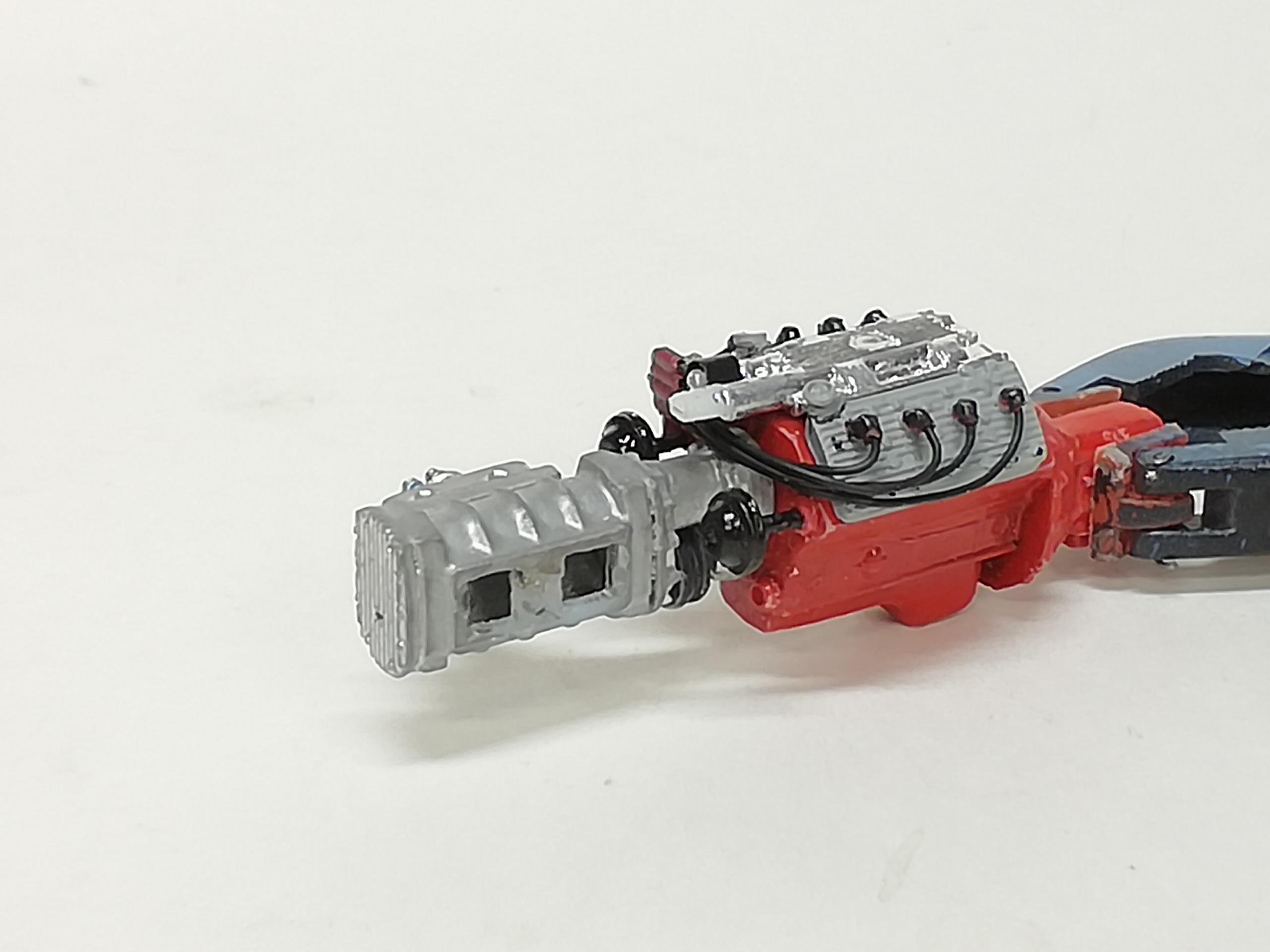
Getting a little more done... Got the engine wired to the scratch built crab type distributor I had originally painted the plug boots red but thought it looked too much like a Fisher price toy lol. Out comes the black. The coil will mount below the pump pulley. Speaking of pulleys, I found a couple in the parts box and added an extended shaft cover made from brass tubing, and a collar mount on the back of the pulley. They were mounted to the front of each head in another set of scratch built collars. The pulleys are in line with the main crank pulley, and I also made sure when installing them that they were up enough for the belt to just clear the top of the blower extension. The generator will go below the pump pulley on the driver's side. These are all mockup shots. The chrome piece on top will probably get a coat of flat. Haven't decided on what color the headers will go. Comments and observations welcome.

-
Just a note. Recovering from triple bypass surgery 6 days ago. Amazing how one has to relearn ones walking balance and small motor movements with finger/thumb control. It's not lost just needs some retuning. Anyway, I will be back to finish it. Cheers.
-
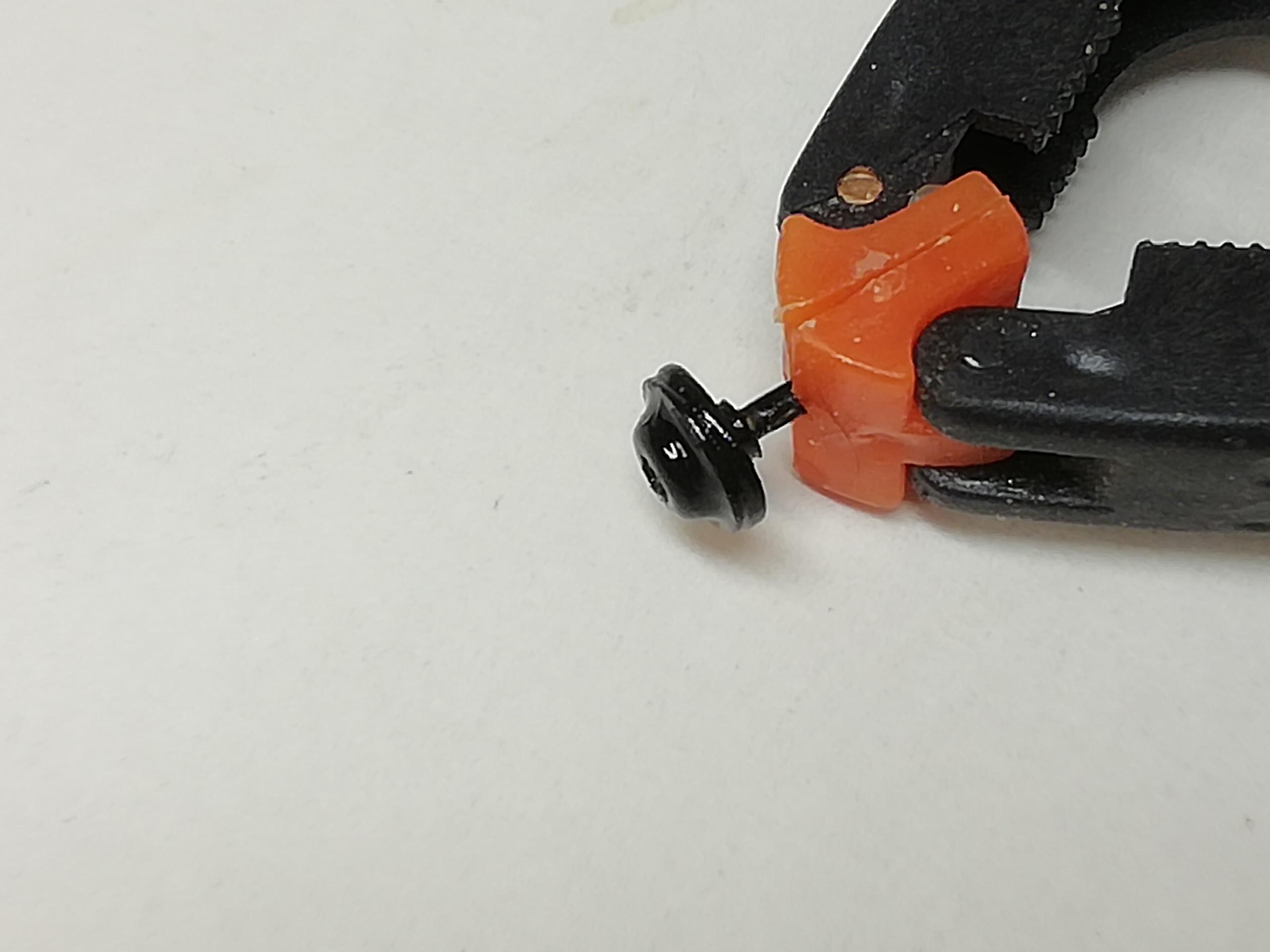
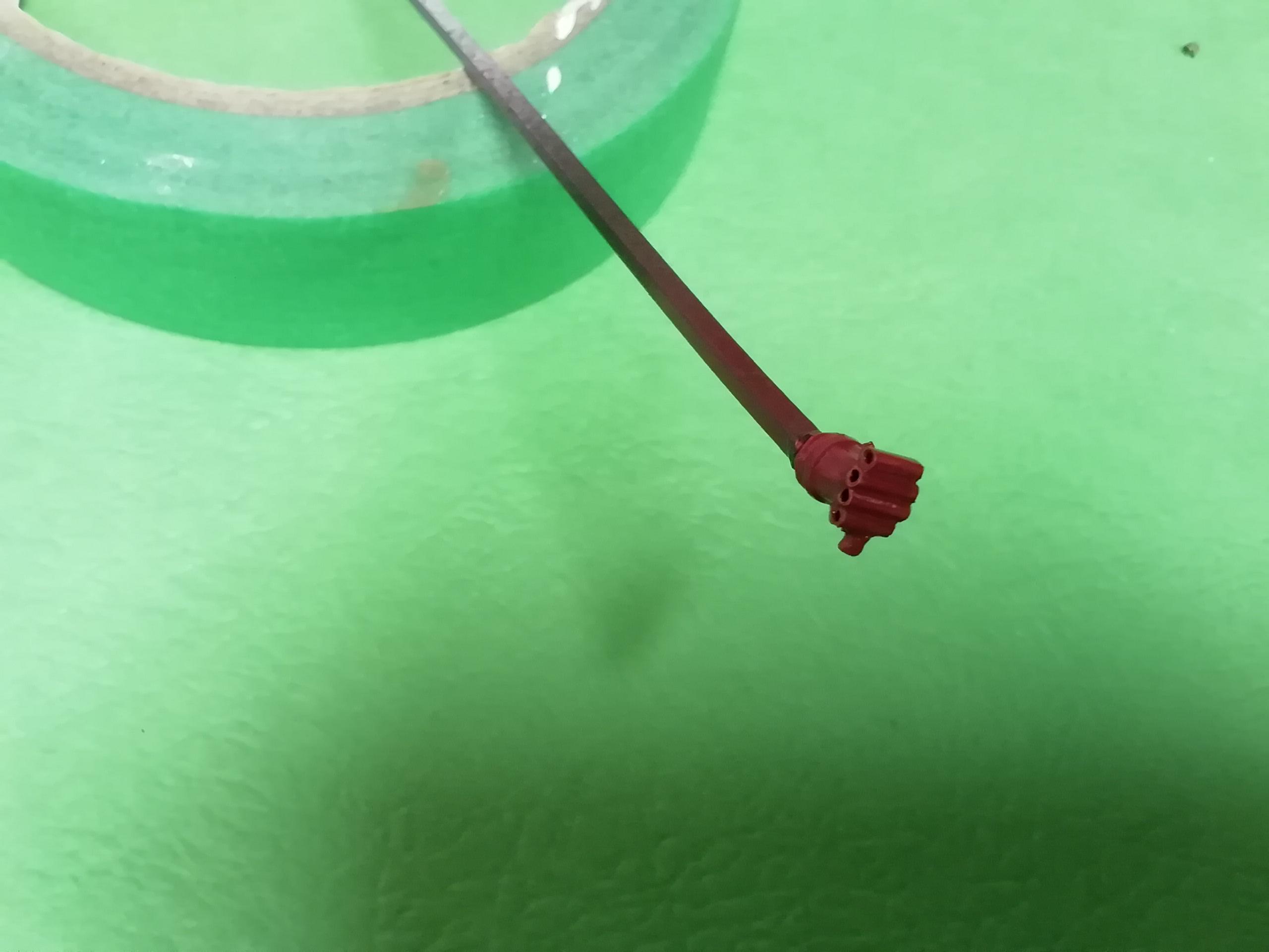
Continuing on, the spark plug connectors are sprayed red. They're small enough to fit on the end of toothpicks I wanted to try something different than a plain Jane distributor, didn't want a magneto either. I've seen this referred to as an e-fire, or crab type. Looked like a candidate for a simplified version. Using the same brass tube as for the plug caps I cut lengths to approximate shape -- better too long than short. I lined them up, applied some thin ca, and filed each one to length, adding the coil tube 90 degrees to the rest. It was attached to the kit distributor after filing down the distributor posts, then sprayed red. A short shaft will be attached to the bottom of the assembly and mounted in to a hole I'll drill in to the side of the engine cover For variety's sake, these are the three reds I've used for (left to right) the engine block, plug connectors, distributor. I have a clear red for the tail light lenses to go. Comments and observations welcome.
-
A
-
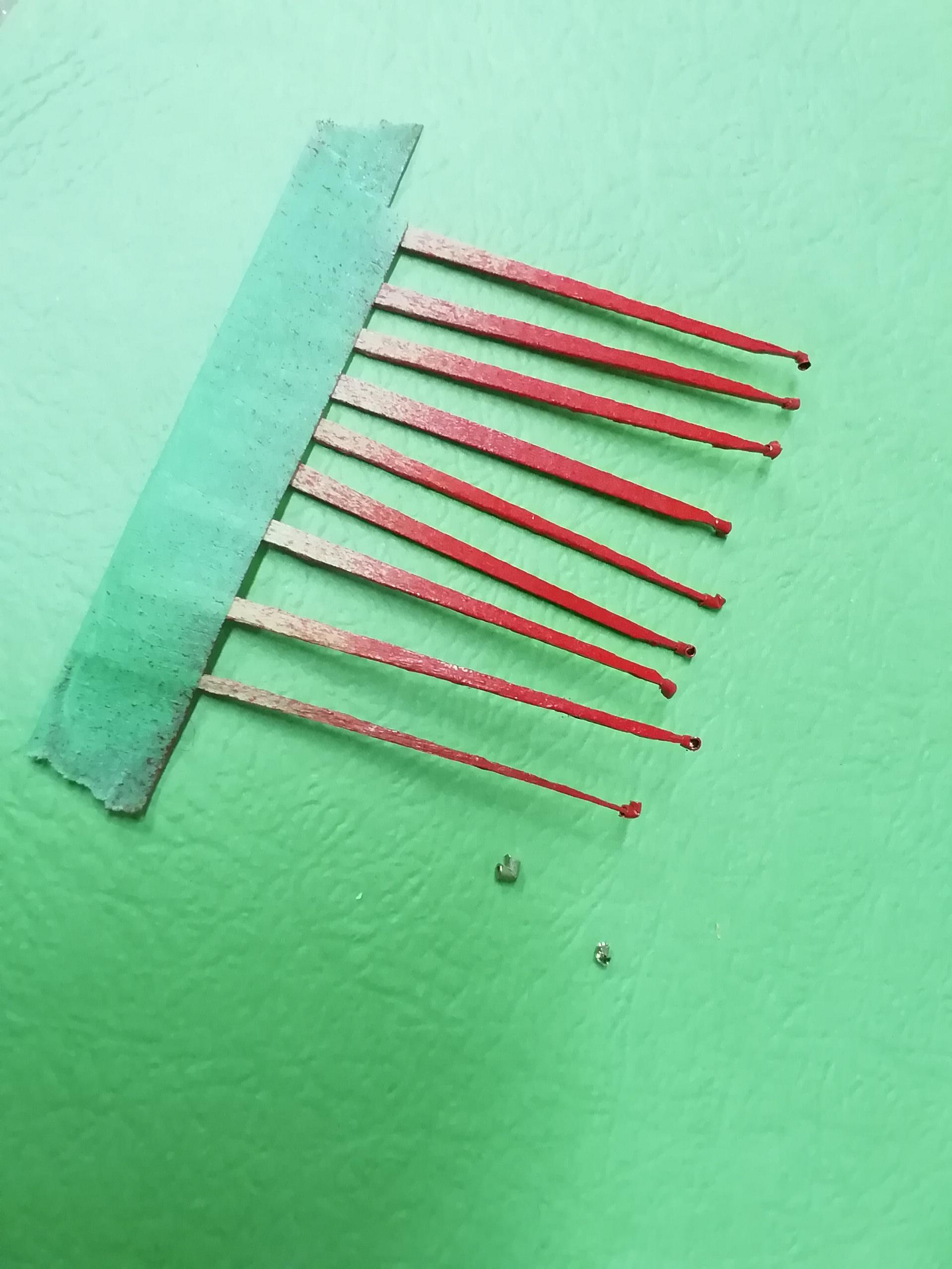
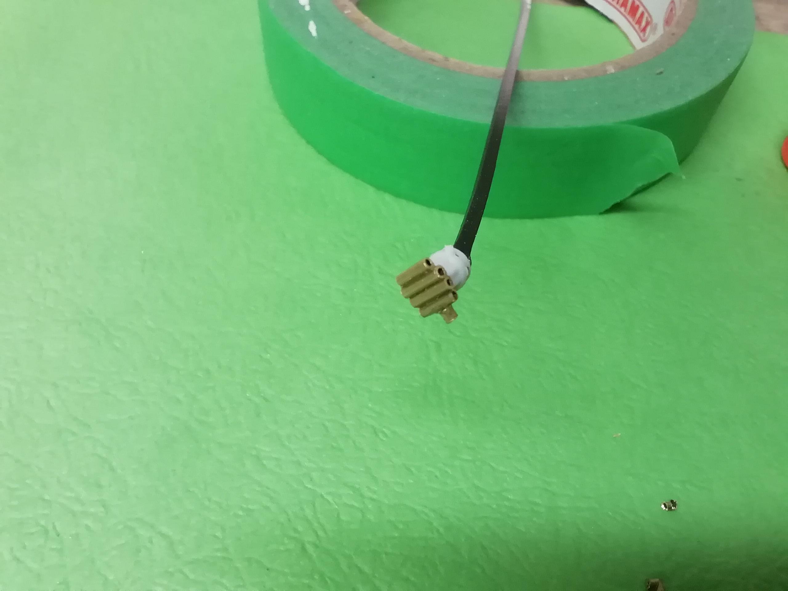
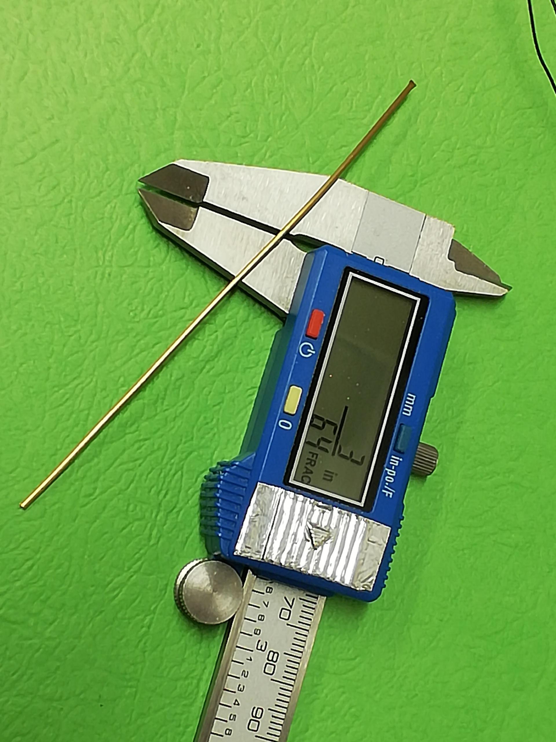
I found an excellent on line tutorial making 90 degree plug connectors using solid core plug wire but my plug wire is multi strand. Another approach is needed. Just so happened to have some lengths of close-enough-diameter brass tube. You can see it miked out to 3/64. It has a thin wall that has a nice fit to the wire I'm using. First the opening needs to be round for the wire to be easily installed. I used a sharp pointed tool to first make the inside round and large enough to accept the point of a tapered square file to ream it. Next I eyeballed where to cut a slot half way through the tube. If it's too far from the end a file will dress it to length Then using a corner of the square file I created a notch that went a little deeper to almost the opposite side of the tube When satisfied it was filed enough (be ready to have more than one that doesn't work out). I inserted the pointed tool I used earlier and g e n t l y bent it down 90 degrees. It was then cut to length and the wire test fitted This is the naked result. It has yet to be slightly filed to remove any burrs, primed, and painted (in this case red), but at the end of the day it'll be just what my flathead needs. I may simulate the white insulator before mounting, we'll see. Comments and observations welcome.
-
Had the same happen to me using Krylon clear but why? Same Krylon clear I've used forever it seems. Then I compared the small print. Both the same till it got to the cleanup part. The old reliable Krylon clear said to use mineral spirits, the new Krylon clear said to use lacquer thinner. I bought a spray bomb of Rustoleum clear that said cleanup with mineral spirits.....problem solved. Pain in the a** this new important change wasn't noted separately on the main picture label. Hope this helps
-

To WIP or not to WIP
Farmboy replied to atomicholiday's topic in General Automotive Talk (Trucks and Cars)
Man, you nailed that one! Like you, the times I've posted and picked out things that needed correction have been more helpful than aggravating. I do wip's 'cause I've always enjoyed reading those done by other modelers. At the end of the day they help improve my skills and attention to detail. At the same time I'm hoping any I do post are at least a bit interesting and maybe even informative....kinda like giving back