
jmpsebring
-
Posts
236 -
Joined
-
Last visited
Content Type
Profiles
Forums
Events
Gallery
Everything posted by jmpsebring
-
 How long between the coats of sealer/clear do you wait before taping over the existing work? Do you think one could put a layer of decals down like carbon fiber and clear over them with some dry coats....before more following layers? Are the pre-mix HOK paints thin enough for spraying? Enquiring minds want to know..
 -
here is the ref I'm using as a guide. Not building this...just something like this. If someone wants to mill me a set of those covers...... .
-
I'll look into that! Where did I put those kit instructions? Is that based on the angled corners?
-
This is more about a build ethic than anything else. Everything I build has a final look I'm going for. Anything outside that look is not as important. It's a balance of time and payoff. This will have a permanent display case and the car will be up on Pro-Jacks, with doors and nose removed. Look at Romell's last side view shots...they are amazing!s The Jacks will have hidden runners running through the base and attached from underneath. It has to hold a wide heavy chassis forever! I might even solder the frame to the Jacks. I didn't spend all this money on hubs and removable wheels and printed rear ends to hide them! Plus I like all cars in the pits more than on the track. I will never put the nose in place, never put the doors on so it's not important that everything fits perfectly and the door hinges make the right arc. That will save hundreds of hours and a huge amount of stress. The time saved will allow me to perhaps build a kool jig that the doors are hanging on while in the pits. I might build only the scene-facing side of the transporter, creating a background wall. That would be really kool because while painting the body, I could also be painting the same type of scheme on the transporter. That means I can "kinda build" a transporter without really building a huge 1/16th truck/trailer...requiring a huge $$$ case and another year of my life. My next Promod will be the Willy's body curbside with only the fitted, working nosed removed. That will save huge amounts of money/time and I will concentrate on a kool motor and paint. I offer this not as an excuse or not to say others are wrong. If you want pistons inside your motor..no problem. Hell, I enjoyed looking at the clyinder walls of Bart's engine block! Go For it!! What's important to you? No matter how detailed it is...someone will ask me if it runs and somebody will tell me how they like to burn their models up in a big crash.... . Others will say.. that's nice and walk away thinking what a waste of time. He could have flipped a house and made money.... We've all been there so enjoy the build..if you get any ideas then great! The cynergy of us building together, raises the joy for all and keeps us all going.
-
It's tricky at times to solder things together. I'm using radio shack 60/40 resincore solder. I'm also using an acid flux. That's the magic juice IMHO. So far I have not used any heat sink. The iron is so hot and the flux allows me to heat the joint and move away in about a second. It didn't even melt the plastic a-pillar with the joint sitting on it!. Plus, I'm not always soldering a joint just once. Tack in point A holding the part in place with my fingers. Tack in point B, inspect, adjust if needed, then go back and re-do point A with acid and solder on the tip already. This time I concentrate on looks. EVERY time I wipe the tip keeping everything as clean as possible. I will cheat as needed. The Lenco rails might not be soldered or even made from brass. I might JB weld a joint if I feel it's impossible to solder some place that will cause problems. Still, overall I think it's far faster and stronger to do this part in brass. Sometimes I'm a 1/32nd away from even touching the joint having trimmed the rod too short...the solder simply fills the area. Romell, chose to push himself to make everthing from scratch. I'm way to lazy for that. I kit bash and compromise everywhere I can. Then there's Dave who works for perfection. I'm not nearly that dedicated. I'm not understanding what you mean. Not the raising the bar part...more why I should raise the bar. Are you saying that the clutch housing should be moved forward or backwards? EXP: engine block,Plate, firewall panel,Tubes, with the clutch housing floating between the tubes? I do know that engine height up and down can not be adjusted now and I worry about sump clearance. I also worry about rear tire body width. I would do some things differently. Having said that, I will make another post.
-
Before and after. Just trying to make a more modern engine. Plus I'm trying to lock in all of the drive's shapes and locations so I can check for clearance.
-
The engine block and heads are right out of the Funny car model. I added to the width, about an 1/18th and wrapped the heads with some thin strips making them smoother and slightly bigger. It also made them the same size as the valve covers. Even the valve covers are stock. I took the Hemi covers and ground down the tops, filled the center with APOXIE putty and sanded them. They are 90% done.
-
Great Ideas! I need to open my mind and re-think painting concepts instead of using modified decals. Your build has me building a brass chassis. Now your painting has caused me to "invest" in an order this afternoon for HOK paints.
-
I get to play some..... Double checking
-
In-process of the cage section. I have only tacked in this side at three places. I plan on removing it to re-gain access to the middle.
-
Day two and more bars
-
Those colors are so pretty. I really do need some HOK kandy colors....I have exactly zero
-
A few more bars in place. That's enough for one days work...I need to dig out. I can really trash a workspace table.
-
exciting!!
-
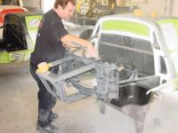
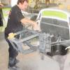
I need some more tri angle shaped plastic to make my bottom edge of the body. That's why the body's bottom edge is uneven. The closest Hobby shop is a hour away. It will have to wait. Thanks everyone for the replys. Bart, your build is awsome. Thanks for the photos. It was all of you that had me drop a major project and start building dragcars again. (that's my story anyway.) this is what I was building. It's a Lotus 77 transkit from Model Factory Hiro in 1/12th along with a scooter for cruising the paddock area.
-
I have in fact spent 100s of hours looking at everything Promod for the last month. Having said that, I'm more the closet engineer than a builder of models. I build to pretend I'm designing my own stuff most of the time. This frame is no different. I know that i prefer the style of the front rear hoops to be at an angle instead of vertical. Plus while there are things all these frames have in common, there are also many different designs out there too. I did notice that many of the tubes running besides the Lenco's tapered in towards the rear. I'm using tubes to the firewall in order to remove the front section while building. Plus it allows a final length adjustment just in case all this 'perfection' ends up being too short or too long ! Once I got this out of the car again, I placed it back on the graph paper and did in fact adjust a couple of the angles. Again , because I soldered everything together, it took only a few minutes to make adjustments. One important note was the use of rod instead of tubing when possible. Tubing is hard to solder the final 'end' closed. the air inside blows the solder away. If using tube I have to cut a vent hole when closing both ends up to allow air to escape. One good side effect was the melting of the plastic at the rear bar. It allows the body to go back into place time after time. Repeatability is so important when prototyping any car..any scale. I had to start with this bar in place to spread the rear roll -under part of the body out a little. It gives the body a touch more modern look .
-
The last step was to put the frame back in the body to double check and then solder a temp front "stand" to set front frame height. I soldered the tube to the center and let it stick out past the floor of the body. Laid a ruler flat across the floor to establish where the runner should be trimmed to. Cut off the extra...and poped out the frame a there it it is. Best of all, the frame pretty much locks into place because it fits so well. Next I will do the outide bars, then connect the A-pillars to them.
-
I've cut one bar to length and soldered it in place. As a serious slot car racer, I have a Hako 936 soldering iron. Great iron! I'm using "lucky Bob's" soldering acid. This is what we use to solder pinions to a motor shafts. It works so fast and well, it ends up needing way less time...therefore way less heat to work. This is the magic stuff that makes this way easier than cutting plastic. The solder simply blends around the joint. Seconds later, it's dry and strong. Plus at any time , I can come back and move to bar if needed . once both sides were soldered together, I unsoldered the runners.
-
So here is the front /rear sections that will fit the body "perfectly" . Now I will solder the real top roof tubes to connect the front and rear together.
-
I know it's a strange way to do things, but I'm doing what the pictures are doing Bart... but I don't fit inside the setup table. I determined where the bottom rear bar would be, and glued it in place. Then I placed the roll bar right up to the roof and mark the bottom of the tubes where they cross the plane of the floor(minus 3/32" to rest on top of the bar. They were cut to length and then attached to the bottom(top) bar. With that angle set and knowing I am right at the top and bottom of the body, I can lock the front and back angles together forever. I soldered four temp runners from the front to the back . They are in the center to keep heat away from the body. Once they were installed, I quickly as possible connected the windshield parts with a touch of solder. I then popped out the whole thing.....and there you go! a completed frame!!
-
I don't really use drawings, but I've always built frames that fit tight against the body by building inside the body. At least the first part of the frame. So I'm cutting 3/32" rod to lay down along the a-pillars. I'm just barely tacking them in place with super glue. It's gonna look a lttle strange, but it will fit well when it's done. This is where and why I'm going with the plastic (or printed) body. It's all the same thickness. If you going full detail, right away you need to battle the uneven thickness of the best resin bodies. I think they are perfect for every thing except these kind of builds. Unless of couse you spend the time grinding.
-
I spent the money, I have most of the parts, I'm starting the 2012 promod racing season. Someone's gotta battle all these up-coming Camaros. Actually, I would be building a Camaro too if this wasn't around. I'm starting with a Revelloution body because it looks pretty close to Andy McCoy's Duster design. The chassis will be brass, the motor is still a question. Most of the builds here take a long time. I'm thankful that many have paved the way allowing all of us to pick up and copy their ideas. Also.... no way would I be building (buying) a 1/16th high detail drag car, if it wasn't for the list of guys well known by builders here. This is 98% $$$ after market model building. So I would like to thank my ex. She has made all of this possible. Let the frames begin!
-
The MSD site has some diagrams for their products..
-
My pirate girl was taken down. Yes it did show a single breast. Sorry if someone found a pea-size breast so offensive....
-
Development of the new JMP Racing engine continue's ! I have a box of spare parts (like all of us) and it has many F1 1/12th parts in it. I'm trying to block in the various drives and componets needed for a big ProMod motor. I used a 6-wheel Tyrrell front wheel hub for my Vacum pump. The pully's are modified Renault V-6 turbo drives. The rear driven belt for part of Jim's new MSD Promag is attached using a Porsche 934 rear torsion bar cap.... with a shortened thinned-out distributor drive plate also from the Renault V6 glued on. The 934 part will likely be an electric water pump attached to the dist drive part with standoffs, all driven off the cam drive. The oil tank is a slot car wheel. On the other side is another drive belt driving the dry sump. A new dry sump pan was made using mostly stacked glued plastic stock. More shots later. This was put up after the conversation about batteries. I don't claim for it to be accurate. I enjoy making cool looking things that are plausible. Plus I'm 56 years old!! It's time to use some of these fantastic shapes while I'm able to still see them. Once I settle on the parts, everything will need brackets and then I can cut down the mounting plate. With hoses, wires, paint and fittings, etc, they will look just fine... for me. What do Carb cars use for fuel pumps? sump.