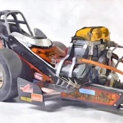
Straightliner59 Posted June 2, 2019 Author Share Posted June 2, 2019 Painted, tires installed. I cut a divot in the end of a piece of .75" aluminum rod, as a tool to help slip the tires onto the wheels, after assembly. I didn't want to find out what might happen, if I had tried to "wrestle" them on. I'll get them permanently mounted before I hit the sack, I think...hope! Quote Link to comment Share on other sites More sharing options...
afx Posted June 2, 2019 Share Posted June 2, 2019 Wheels look great! Quote Link to comment Share on other sites More sharing options...
Straightliner59 Posted June 2, 2019 Author Share Posted June 2, 2019 1 hour ago, afx said: Wheels look great! Thanks, JC. They are definitely better than those abominations that come in the box(es)! Quote Link to comment Share on other sites More sharing options...
Straightliner59 Posted June 3, 2019 Author Share Posted June 3, 2019 If I can do daily updates, that means I am making progress! I got the drag link all put together and installed. I still need to paint the "hardware", but, this is otherwise done. I had a couple of spokes break away from the outer rim, on this side. I figured the easiest way to fix that was to put on a "rollout" plate. Next up is mopping up behind myself, and beginning the induction setup. I really feel like it's the Enderle injectors that will totally "make" this dragster. It's getting closer... Quote Link to comment Share on other sites More sharing options...
afx Posted June 3, 2019 Share Posted June 3, 2019 I've seen these plates on the front wheels of FEDs many times but what is there purpose? Quote Link to comment Share on other sites More sharing options...
Straightliner59 Posted June 3, 2019 Author Share Posted June 3, 2019 They are to give the car more "rollout", which i essentially a bit of leeway, with the starting line beam. The front motorcycle tires and wheels had such a small profile, that the beam didn't always "see" them. The plate made for a larger "target". I hope that clarifies it, some. Quote Link to comment Share on other sites More sharing options...
afx Posted June 3, 2019 Share Posted June 3, 2019 Makes sense. I assume the plate is very thin and light but still unusual that they would install it on one side only. Quote Link to comment Share on other sites More sharing options...
dodgefever Posted June 3, 2019 Share Posted June 3, 2019 2 hours ago, Straightliner59 said: If I can do daily updates, that means I am making progress! I got the drag link all put together and installed. I still need to paint the "hardware", but, this is otherwise done. I had a couple of spokes break away from the outer rim, on this side. I figured the easiest way to fix that was to put on a "rollout" plate. Next up is mopping up behind myself, and beginning the induction setup. I really feel like it's the Enderle injectors that will totally "make" this dragster. It's getting closer... Been a while since I checked this thread. Looking great! Quote Link to comment Share on other sites More sharing options...
Snake45 Posted June 3, 2019 Share Posted June 3, 2019 2 hours ago, afx said: Makes sense. I assume the plate is very thin and light but still unusual that they would install it on one side only. Since the beam is reading the wheels in direct profile, a second one would be redundant--one is all you need. Quote Link to comment Share on other sites More sharing options...
afx Posted June 3, 2019 Share Posted June 3, 2019 (edited) 39 minutes ago, Snake45 said: Since the beam is reading the wheels in direct profile, a second one would be redundant--one is all you need. I was thinking of the balance across the axle, one front wheel being slightly heavier than the other traveling at very high speeds. Obviously it wasn't an issues as they were used for some time. Edited June 3, 2019 by afx Quote Link to comment Share on other sites More sharing options...
Straightliner59 Posted June 3, 2019 Author Share Posted June 3, 2019 6 hours ago, dodgefever said: Been a while since I checked this thread. Looking great! Thank you, Stu! It's getting closer and closer. Quote Link to comment Share on other sites More sharing options...
Straightliner59 Posted June 9, 2019 Author Share Posted June 9, 2019 (edited) Well, it's happening; I have begun construction of the last major assembly for this project: the Enderle injection setup. I've somewhat explained the history of the stacks, themselves. The manifold has its own story, as well. This is the fourth manifold I've started building, since I decided this thing needed Enderle injection, instead of the Hilborn unit I first installed. They've floundered for various reasons, mainly stemming from a lack of planning, on my part. In order to atone for my sins of the past, I planned a bit this time. That dictated that the throttle bodies needed to be cross-drilled before they were to be installed (In these photos, nothing is cemented, beyond the manifold flanges and the bosses for the mag, and the water outlet. In order to assure that the throttle rod bores were properly aligned, I devised this simple tool from a short length of 1/8" square K&S brass channel. The throttle bodies are .100" styrene rod. In its manufactured state, the channel is too narrow, inside, to fit the plastic rod. As luck would have it, my Nicholson 6"mill bastard just happens to be .100" thick. After a bit of work, the throttle body rod fit snugly, in the channel. Next, I measured about .040" from one end of the channel, and marked it. I then marked a line longitudinally down the center of the "spine" of the channel. At the intersection of these lines, I drilled a hole with a #80 bit. By laying the cut sections of the throttle bodies/intake runners in the channel, and aligning them, I could, by drilling from one side, and then the other, achieve a bore that went straight through the T.B. assemblies, and I didn't have to worry about if they were actually going to align! In these photos, you can see how the rod assembly fits into the drilling jig, along with the T.B.s sitting on the manifold, bisected by the throttle rods. Other photos show the beginnings of "the brain" of the system, as well as the manifold adorned with the injector stacks. I need to install a few ribs, down in the valley. I'm not sure how to, or even if, I will address the "ENDERLE" lettering, on the manifold. I'm considering a tiny decal, of a 3-D vectored graphic, on which I would create the appearance of raised lettering via light and shadow. Anyway... Edited June 9, 2019 by Straightliner59 Quote Link to comment Share on other sites More sharing options...
gasser59 Posted June 9, 2019 Share Posted June 9, 2019 By jove, I think you've got it this time Dan. That's looking sharp and once cleaned up with a bit of paint, it will be very convincing. Quote Link to comment Share on other sites More sharing options...
Mooneyzs Posted June 9, 2019 Share Posted June 9, 2019 Daniel... This build is looking good and coming along great. Really love what you have done on it so far. and Love that you made the body out of Aluminum as well as the disc on the front wheel to break the Beams. Very cool touch Quote Link to comment Share on other sites More sharing options...
Straightliner59 Posted June 9, 2019 Author Share Posted June 9, 2019 5 hours ago, gasser59 said: By jove, I think you've got it this time Dan. That's looking sharp and once cleaned up with a bit of paint, it will be very convincing. Brad, I think you might be right! I can certainly live with this one (so far! ), Feels good to be closing in... 3 hours ago, Mooneyzs said: Daniel... This build is looking good and coming along great. Really love what you have done on it so far. and Love that you made the body out of Aluminum as well as the disc on the front wheel to break the Beams. Very cool touch Thanks so much, Chris! I appreciate your kind words. I have the article I used, in which Tom Hanna explains (with a few photos) how to build one of those bodies for a 1:1 car. If you ever want to build one, I can get it to you--I mean it is digitized, and all.Thanks again, sir! Quote Link to comment Share on other sites More sharing options...
Straightliner59 Posted June 14, 2019 Author Share Posted June 14, 2019 (edited) It's been a frustrating week, working on these injector/hose assemblies. I finally got them all on the manifold. Still need to "pose" them, so they look natural, and do some touch up on the assembly. The Frankenstein mag fits (it's just sitting up there, right now). I want to make 90 degree boots for the plug ends of the ignition wires, but, I'm not dead-set against straight ones. I have eight nights off, between now and the end of the month, to finish this thing! If I get everything done, but the decals (they are pretty much ready to print), I'll call it done, for the "BOYD" deal. I need to build linkages, finish plumbing the fuel system, and build a set of headers. After that, it'll be just down to any little things I missed. I think I have this! Edited June 14, 2019 by Straightliner59 Quote Link to comment Share on other sites More sharing options...
Flat32 Posted June 15, 2019 Share Posted June 15, 2019 What did you use for that perfect size hose material?? It looks fantastic. Routing can look good when hoses go to the opposite side of the barrel valve manifold. Hoses would cross, but bends are less sharp. You have them looking pretty darn natural already. Linkage separates the men from the boys in my mind. Quote Link to comment Share on other sites More sharing options...
Straightliner59 Posted June 15, 2019 Author Share Posted June 15, 2019 14 hours ago, Flat32 said: What did you use for that perfect size hose material?? It looks fantastic. Routing can look good when hoses go to the opposite side of the barrel valve manifold. Hoses would cross, but bends are less sharp. You have them looking pretty darn natural already. Linkage separates the men from the boys in my mind. Thank you, Ray! I appreciate it. That is old MSC 1/25 plug wire material. I've never measured it, but, I'd guess it's about .020", in diameter. I'm running low on it, and wish I had more. I have tons of it, in vibrant colors, of course. Yes, regarding the hoses. I wish I'd opted for the crossover, instead of this way--I mean I have photos of them both ways, but, crossing them would definitely have been easier. I had an injector break, so, I have to replace it, now, before I can move on to the linkage. I am hoping to have it (the linkage) finished before I go to work, Monday night. Once the stacks are on, this assembly will have around 80 pieces! Quote Link to comment Share on other sites More sharing options...
Straightliner59 Posted June 17, 2019 Author Share Posted June 17, 2019 The manifold assembly is nearly complete! I need to add a couple of square plugs, the linkage arm for the throttle cable to attach, a bracket to anchor the shielded part of the throttle cable, and some touch up. Here are some shots, form several angles. I'll finish this up, then move to finish the headers. They are brass, so I can test out my new soldering gadgets. I still need to replace one zip tie, and build and install another return line, and zip tie it to the chassis. I have a little bit of smoothing/polishing of the cowl, to do, and install the windscreen, and some PE dzus fasteners, and that will be done. It's almost punch-list time! I have the decal art done. I need to run a test print of that, and make any adjustments... Quote Link to comment Share on other sites More sharing options...
afx Posted June 17, 2019 Share Posted June 17, 2019 Manifold looks great Daniel. Quote Link to comment Share on other sites More sharing options...
Straightliner59 Posted June 19, 2019 Author Share Posted June 19, 2019 On 6/17/2019 at 6:50 AM, afx said: Manifold looks great Daniel. Thanks, JC. It was quite a wrestling match! Quote Link to comment Share on other sites More sharing options...
Straightliner59 Posted June 21, 2019 Author Share Posted June 21, 2019 Fuel system is all but finished! Headers, stacks and plug wires are the last three major assemblies. I have one header flange almost finished. The pipes are bent, with pins inserted. I have to finish the right side return line (which includes drilling the tank--oops!), and get it zip-tied to the chassis. I want to make 90-degree boots for the plug ends. I've done it, before. It's a pain, but, I want them! Anyway, here are a few photos of the fuel system--still a few loose ends to tie up, and some touch up, to do... Quote Link to comment Share on other sites More sharing options...
sflam123 Posted June 22, 2019 Share Posted June 22, 2019 On 6/3/2019 at 8:24 AM, Straightliner59 said: They are to give the car more "rollout", which i essentially a bit of leeway, with the starting line beam. The front motorcycle tires and wheels had such a small profile, that the beam didn't always "see" them. The plate made for a larger "target". I hope that clarifies it, some. They also provide a "target" for the finish line beams. There were occasional issues with the finish line beam missing the skinny tire/wheel and early on some races were incorrectly determined to the second place car because the finish beam failed to detect the first wheel across. There was an incident several years ago with the Pro Stock Motorcycles at the US Nationals in Indianapolis where the finish line beam failed to detect Steve Johnson defeating one of the HD's (Matt Smith?), but fortunately ESPN had a camera at the finish line that caught Johnson crossing first. After a couple of days of NHRA reviewing the film and interviewing the participants, Johnson was declared the winner. Pro Stock Motorcycles now incorporate these same plates. Quote Link to comment Share on other sites More sharing options...
Straightliner59 Posted June 22, 2019 Author Share Posted June 22, 2019 2 hours ago, sflam123 said: They also provide a "target" for the finish line beams. There were occasional issues with the finish line beam missing the skinny tire/wheel and early on some races were incorrectly determined to the second place car because the finish beam failed to detect the first wheel across. That is absolutely correct, as well! I seem to recall a time that a rider had "lost", because he was still pulling, carrying the front wheel across the beam, and didn't get recorded, until the rear wheel broke the beam. Quote Link to comment Share on other sites More sharing options...
Straightliner59 Posted June 24, 2019 Author Share Posted June 24, 2019 Well, the entire fuel system is finished. The headers are built, and only need a clean up and paint, to be finished. I have the decals printed. Gotta' keep pushin' on... Quote Link to comment Share on other sites More sharing options...
Recommended Posts
Join the conversation
You can post now and register later. If you have an account, sign in now to post with your account.
Note: Your post will require moderator approval before it will be visible.