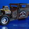
kennb Posted October 27, 2011 Author Share Posted October 27, 2011 Frame update KennB Quote Link to comment Share on other sites More sharing options...
Dr. Cranky Posted October 27, 2011 Share Posted October 27, 2011 You are the purest definition of a STYRENE ADDICT! WOW! Quote Link to comment Share on other sites More sharing options...
Jantrix Posted October 27, 2011 Share Posted October 27, 2011 Some info on the Italia for folks like me, unfamiliar with this car. Check out page two, it has some good interior pics. Ken, the couple of sources I've checked says this car was built on the Hudson Jet chassis, if that helps you. That interior is something else. The seats look like they are three separate cushions, alas more work for you. http://auto.howstuffworks.com/1954-1955-hudson-italia.htm http://www.conceptcarz.com/vehicle/z11671/Hudson-Italia.aspx Quote Link to comment Share on other sites More sharing options...
Hakan ERYILMAZ Posted October 27, 2011 Share Posted October 27, 2011 Really amazing Quote Link to comment Share on other sites More sharing options...
kennb Posted October 27, 2011 Author Share Posted October 27, 2011 I have the control arms set up and the steering set up.Both will be working. I also have the rear wheel wells adjusted and installed. The tranmission mount is in place. The seats are very different and the backs are 2 piece with screws holding them to a formed plywood base that is covered with leather and padding. I will be getting to those when the frame is further along. They almost look like the more modern racing seats the way the plywood backer is formed. The chassis is indeed based on the Jet but what is not said anyplace is that there was some adjustments made to accommadate the lower body. I have found no photos or drawing of the Jet chassis setup in any form. KennB Quote Link to comment Share on other sites More sharing options...
Kaleb Posted October 27, 2011 Share Posted October 27, 2011 Einstein of plastic, Absolutely Genius. You my friend are Einstyrene. Quote Link to comment Share on other sites More sharing options...
Foxer Posted October 27, 2011 Share Posted October 27, 2011 I'm just enjoying the heck out of watching this ... as I did with the Tatra. Quote Link to comment Share on other sites More sharing options...
jbwelda Posted October 28, 2011 Share Posted October 28, 2011 just amazing and im only talking about that frame jig you rigged up there. ive tried so many times to build something like that and rarely came close. and the car itself, just incredible, incredible. thanks for the answer on the "why?" question too, very inspiring. please keep us up on progress! how interested are you in Maserati Birdcages? Quote Link to comment Share on other sites More sharing options...
kennb Posted October 28, 2011 Author Share Posted October 28, 2011 I am ending up with operating sterring and suspension. I also am adding working shocks. You can see how this is done from the photos. The copper wire slips in the smaller tubing with ease, the shocks will not rebound on their own but will work with assistence. The steering is a simple setup the I will have an adjustable tie rod in place. I have yet to place the springs but will place them after everything is painted. Thanks again for looking and all the nice comments. KennB Quote Link to comment Share on other sites More sharing options...
shucky Posted October 28, 2011 Share Posted October 28, 2011 Agree with everyone else. KennB you are a true artist of styrene. You do wonderful things with the stuff. I've said it before, but I've always believed you can pretty much build anything from styrene and you've definitely shown us that. Very nice job again and I'm watching in amazement. Thanks for posting your outstanding work. Quote Link to comment Share on other sites More sharing options...
LAone Posted October 28, 2011 Share Posted October 28, 2011 i have surpassed the wow factor, now im in shock and regaining conciousness..lols amazing work man. im enjoying this every update. Quote Link to comment Share on other sites More sharing options...
kennb Posted October 29, 2011 Author Share Posted October 29, 2011 I am going to take a break from the frame for a while and start working on the interior. I have the dash done and the floor was roughed out before. But, as I am working it is all wrong and going to be trashed along with the door panels. I drew some rough scale drawings for the seats and then flatened them out so I could cut the plastic to size. After a few trys this is what i came up with for the back panel that the cushions are screwed to. Will post the finished seat this afternoon Thanks for looking. I hope that as you see how this is done you can find things to use in your own model building. KennB Quote Link to comment Share on other sites More sharing options...
84vanagon Posted October 29, 2011 Share Posted October 29, 2011 One word.... WOW! Quote Link to comment Share on other sites More sharing options...
Foxer Posted October 29, 2011 Share Posted October 29, 2011 I'm assuming you use some kind of heat to shape that seat back. Could you explain your technique more? It looks like you have curves going in two directions! Quote Link to comment Share on other sites More sharing options...
kennb Posted October 29, 2011 Author Share Posted October 29, 2011 The forming of the styrene that I am using can be handled in 2 ways. Use of heat or very hot water of the shaping with needle nose pliers.l used the pliers to form the seat backs. A little at a time curving the styrene to the desired shape. There is also a small U shaped piece towards the bottom on the back that forms the bottom flair at the back. This plastic holds its shape fairly well, which is why I use it. (I get it out of U.S. plastics in Ohio.) I used heat to form the spring mounts on the A frames on the front of the frame, and the hub caps. I used heat as little as possible since on larger pieces it is harder to control. The Evergreen styrene is far to stable to form and hold the shape. It is a different type of plastic. All the plastic starts out at .40 and filed and sanded to different thicknesses or layered to get the desired thickness. I hope that you can follow how I shaped the seat backs. If not i can try do do a short demo video at some point. Thank you for the questions and comments. KennB Quote Link to comment Share on other sites More sharing options...
kennb Posted October 29, 2011 Author Share Posted October 29, 2011 Here is one of he seats roughed out. It is assembled temporarily. I did get a little carried away and made it so it will fold forward like the orgional does. It was a mater of a few pins is all so was very easy to do. The seat tracks show when the seat is pushed back. They will be chromed. KennB Quote Link to comment Share on other sites More sharing options...
charlie8575 Posted October 29, 2011 Share Posted October 29, 2011 Wow.... Easily one of the most impressive builders I've run across. Charlie Larkin Quote Link to comment Share on other sites More sharing options...
MrObsessive Posted October 29, 2011 Share Posted October 29, 2011 Wow! All I can say is.................... Quote Link to comment Share on other sites More sharing options...
bobthehobbyguy Posted October 29, 2011 Share Posted October 29, 2011 Finding drawings for some of my projects is very difficult. Specs are even more vague. I have the wheelbase and tread and some drawings I found online for this one. All my work is done with an exacto knife, wood ruler , some needle files and a pair of needle nose pliers. I dont have any fancy equipment and use the drawings for scaling the best I can. Most things are done by eye. As for things I dont have information on, i.e. the frame, I try to use what was common practice for the era. This can be a challange for some things. Some things there is just no information on, so you have to depend on the photos that you do have for the details. As in case of this car and the Tatra, there is the fact that over the years the cars have changed and it ends up that you dont have any 2 cars that are the same. With my Tatra, cars even the same year were not the same as things along the line were changed at the whim of the company. Cars like the Italia were all hand built and this ment that there was even variations within this small group. All my research is limited to what I can find online. I have the Tatra build in this forum, I started it in June and finished in July. I also have photos of the build on photobucket. There are some albums there of my paper builds, and a few others cars I am working on. http://s126.photobuc...-bug/2nd%20set/ As for the plastic I use. It is thermal setting plastic that I buy in 40" x 72" sheets, .40 (thousanths) that I get from a supplier in Ohio. I can get about 6 cars from 1 sheet, depending on the car, and how many times i have to remake specific parts. If I am not happy with something I restart and throw the previous away, hence "wasting" material. I think I have responded to the questions. Any other questions are welcome and I will answer the best I can. I enjoy the process of construction and willing to share how I do it. You may find that you can use some of the techniques and even improve upon what I do. Someone mentioned in one of the posts that this is art. It is more closely related to an art form in as that I am as accuratly as possible, with what I have, trying to show the feel, the texture, and look of the car as opposed to detailing each nut and bolt. I use no commercial parts but will steal plastic from swizzle sticks, as shown in the tailights in this picture. The glazing is a coke bottle and donut container. Thanks for the continued support and comments. I will have more photos of this car later today as I make progress on the frame, steering and rear end. KennB Wow. Just saw this thread. You are a true artist. Would you give a little more information about the plastic you use? Also maybe the name of your supplier. Thanks, bobthehobbyguy Quote Link to comment Share on other sites More sharing options...
Ryan S. Posted October 29, 2011 Share Posted October 29, 2011 This is true artistry and is absolutely mind blowing. I can't believe how you've taken plain sheet stock and turned it into what you have. Thank you for sharing your craftsmanship. Quote Link to comment Share on other sites More sharing options...
kennb Posted October 30, 2011 Author Share Posted October 30, 2011 Here is the link to my supplier for plastic. The thicknesses vary but I use .40 It is thermal setting, i.e. for vacuforming. it is a commercial grade. I use liquid glue and superglue. As you can see it takes shape very nicely and paint very well. They will sell in single sheets although I buy in quanity since I use it for my 1/2" scale trains. http://www.usplastic...22883&catid=715 KennB Quote Link to comment Share on other sites More sharing options...
John Teresi Posted October 30, 2011 Share Posted October 30, 2011 Kenneth......this is so cool man.....very nice scratch building. Quote Link to comment Share on other sites More sharing options...
kennb Posted October 30, 2011 Author Share Posted October 30, 2011 This morning I started the windshield framing. Starting with some cut strips and 1 cut piece for the foot around the base (where it forms to the cowel) I assembled the parts as shown. I also added some small scrap on the unerside to act as a "snap fit" to the body. It is removable this way and can be put back in place after everything is painted and chromed. So far everything that is chromed is a seperate part. This makes the painting a lot easier and the chrome parts a snap to do. The only parts that are chrome and attached permenently will be the side spears and the rear fender gravel shield. I dont know how I can do them any other way, as small as they are. Thanks again for all the comments. They make me try to do things even better. KennB Quote Link to comment Share on other sites More sharing options...
Tony T Posted October 30, 2011 Share Posted October 30, 2011 Wow...coming along great, Kenneth! Quote Link to comment Share on other sites More sharing options...
Deathgoblin Posted October 31, 2011 Share Posted October 31, 2011 Looking great! Are you going to do the top on this one? How about an engine. The work on your Tatra was amazing and I can't wait to see how this turns out. Pure artistry. Quote Link to comment Share on other sites More sharing options...
Recommended Posts
Join the conversation
You can post now and register later. If you have an account, sign in now to post with your account.
Note: Your post will require moderator approval before it will be visible.