bill-e-boy
-
Posts
929 -
Joined
-
Last visited
Content Type
Profiles
Forums
Events
Gallery
Everything posted by bill-e-boy
-
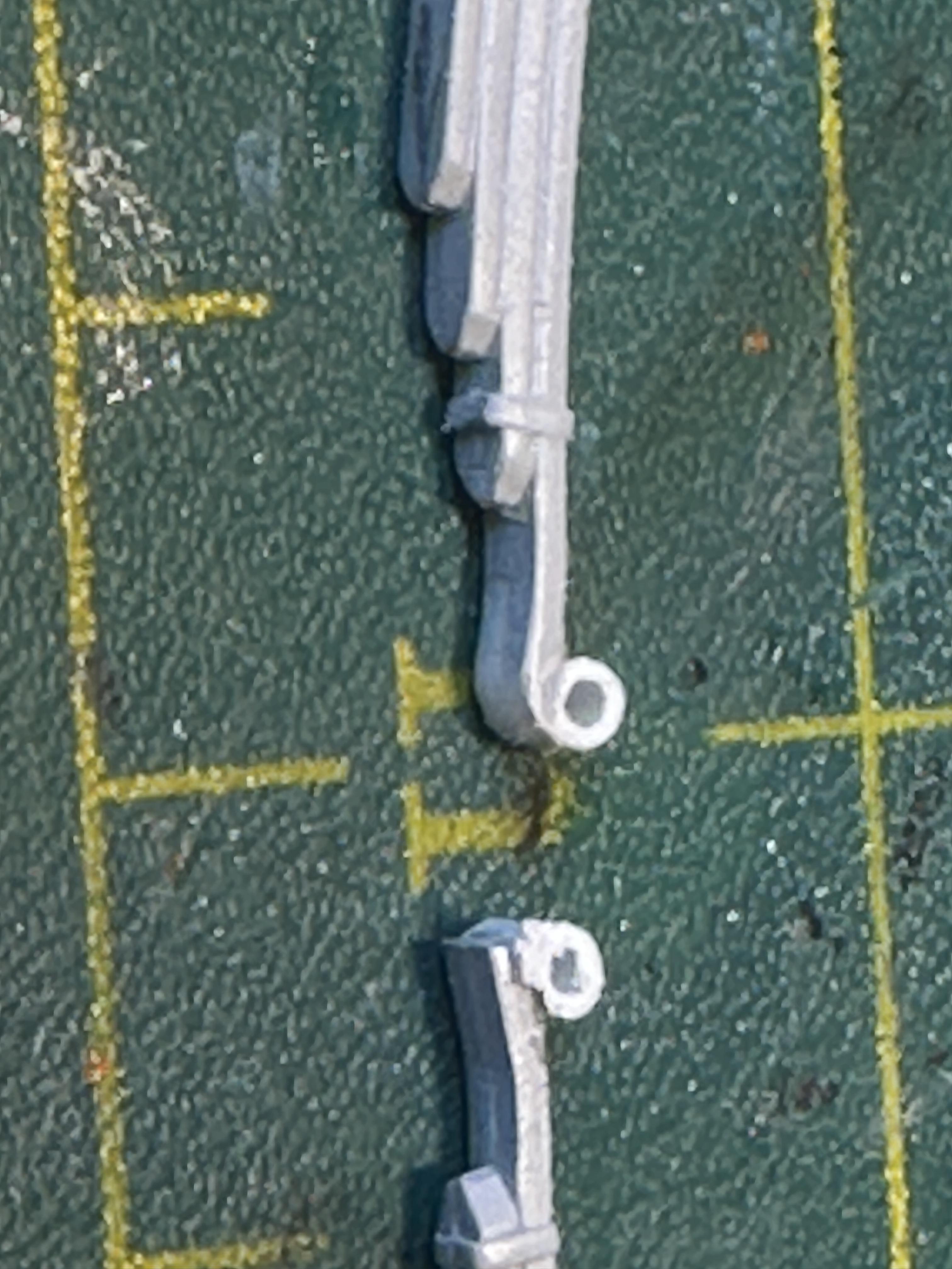
Well I have removed the springs and prepped them to move them rear wards. I tidied the springs up by giving them an eye at the from and reshaped the rear to go into slipper blocks I made up mounts for the spring eyes and slipper blocks and got them mounted up. I have since made reinforcing gussets that go under the spring mounts A quick visit to the paint shop to make it all pretty The wheels and trim rings are from an AMT 40 Coupe A shot of the underside showing the workings And the 34 PU fenders glued and being held in place while the glue sets up Thanks for looking

-
34 Hot Rod Pickup
bill-e-boy replied to bill-e-boy's topic in WIP: Model Trucks: Pickups, Vans, SUVs, Light Commercial
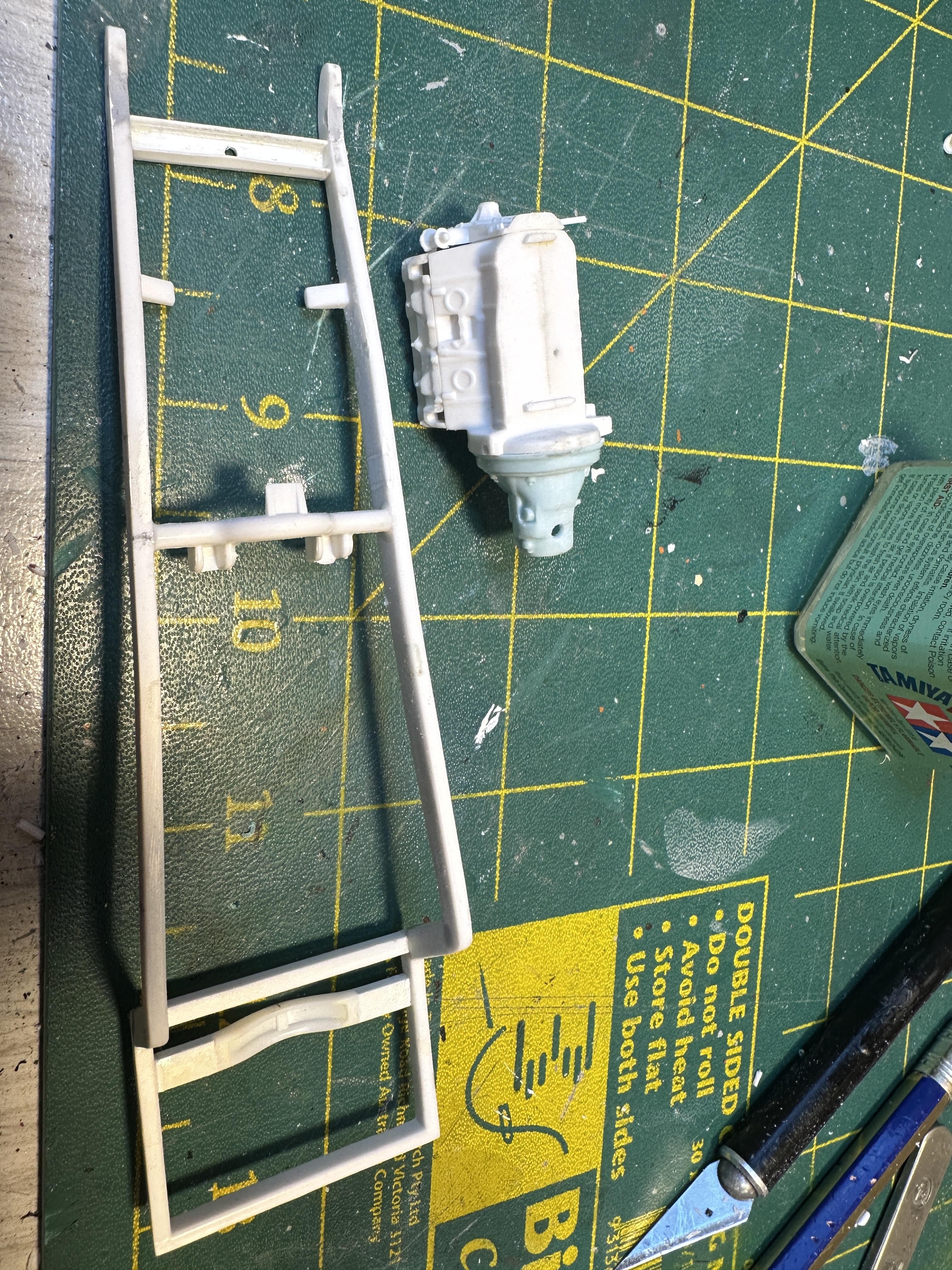
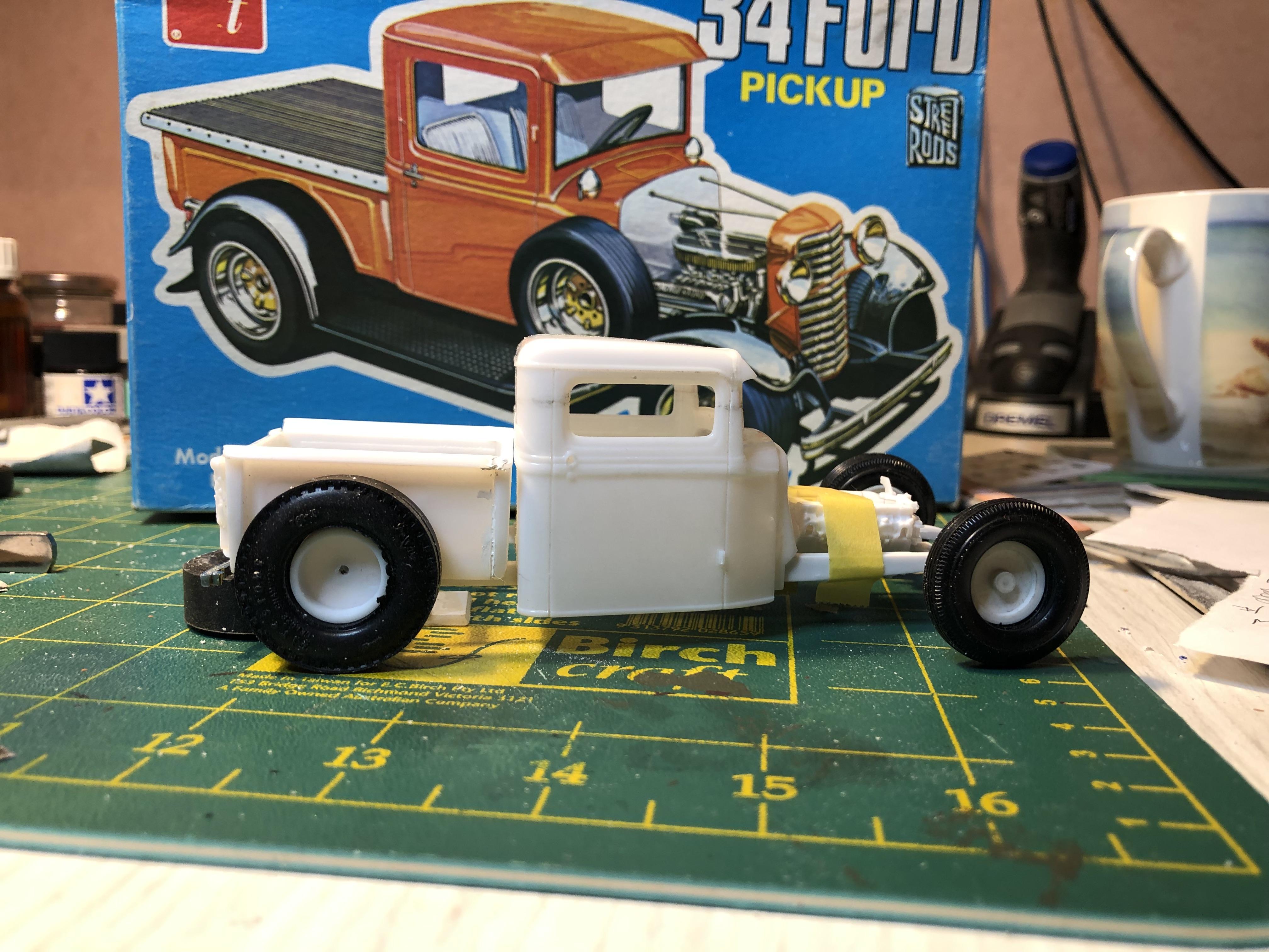
@Kit Karson - haven't seen the "Keep on Truckin..." poster in a while 🤣 @Bullybeef - the trailer is almost done. It is in my "Banger" build thread but will put one up here when it is did. The motor and most of the chassis are from the Revell roadster so I have used the roadster motor mounts. I have already moved the trans mount so hopefully it will be OK. Leaving the trans mount where it was would have the motor taking up most of the cab - it is not a drag car🤪 Not too sure about the "pro" thing though And yup - when kit-rodding it is all about mockup, adjust, mockup, swear, adjust, mockup and repeat many times Any way a bit of progress At the moment I am finessing the cab and PU bed to chassis fit - a lot of the above going down Thanks for looking
-
The mirror is tilted - mounted on a wedge. The upstands just push into their holes so I could make some shorter ones for the back easily enough. But it is done and I was happy with it and I proved my concept worked
-
Cool project. I like the modern roof line and it suits the lines from the tail fins. There is a 57 Ford around down these ways with an ealy Oz Falcon coupe roof fitted. Fins and a racy top looked real cool. And yup the 57 Chrysler is a huge car - I compared it to a 56 Dodge resin I built a few years ago and the size difference is remarkable. But in saying that I reckon Virgil Exner got the proportions right on the money with his 57 cars.
-
34 Hot Rod Pickup
bill-e-boy replied to bill-e-boy's topic in WIP: Model Trucks: Pickups, Vans, SUVs, Light Commercial
Thanks Bil. Most of the early AMT 3n1's had motors with trans adaptors - just most of the hot rod motors got used. I had a friend who built vintage stockers and I he gave me all the excess hot rod parts. But in this case the nailhead was ditched for a big rrrrs shotgun motor when I built the 40 Coupe -
34 Hot Rod Pickup
bill-e-boy replied to bill-e-boy's topic in WIP: Model Trucks: Pickups, Vans, SUVs, Light Commercial
Or in my stash🤪 -
34 Hot Rod Pickup
bill-e-boy replied to bill-e-boy's topic in WIP: Model Trucks: Pickups, Vans, SUVs, Light Commercial
Hi Dan - looks like your build is at a similar stage to mine. That's a big task - putting fenders on a lo-boy. I know what you mean about 1/24th - there is not a heck of a lot of difference in scales between 1/25th and 1/24th but put the same subjects side by side - what a difference. I may need to change the tow vehicle to a 1/24th to keep the scales looking right - but I have precious few Monogram kits mainly for the same reasons you have. The other reason for a tow vehicle change is that an A is smaller than a 34 truck but with the scale differences the truck looks a lot smaller. A rabbit hole I will need to plug -
34 Hot Rod Pickup
bill-e-boy replied to bill-e-boy's topic in WIP: Model Trucks: Pickups, Vans, SUVs, Light Commercial
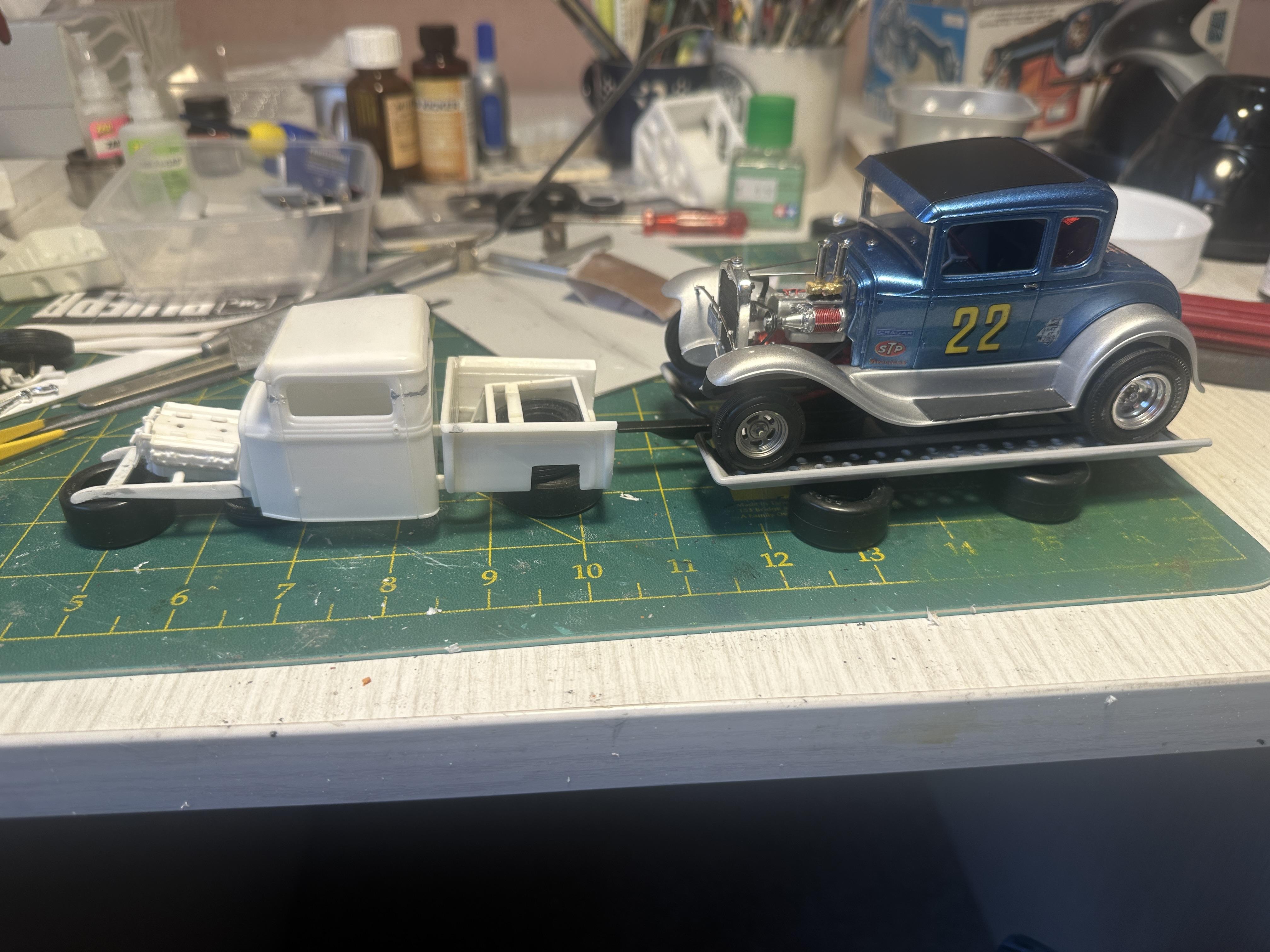
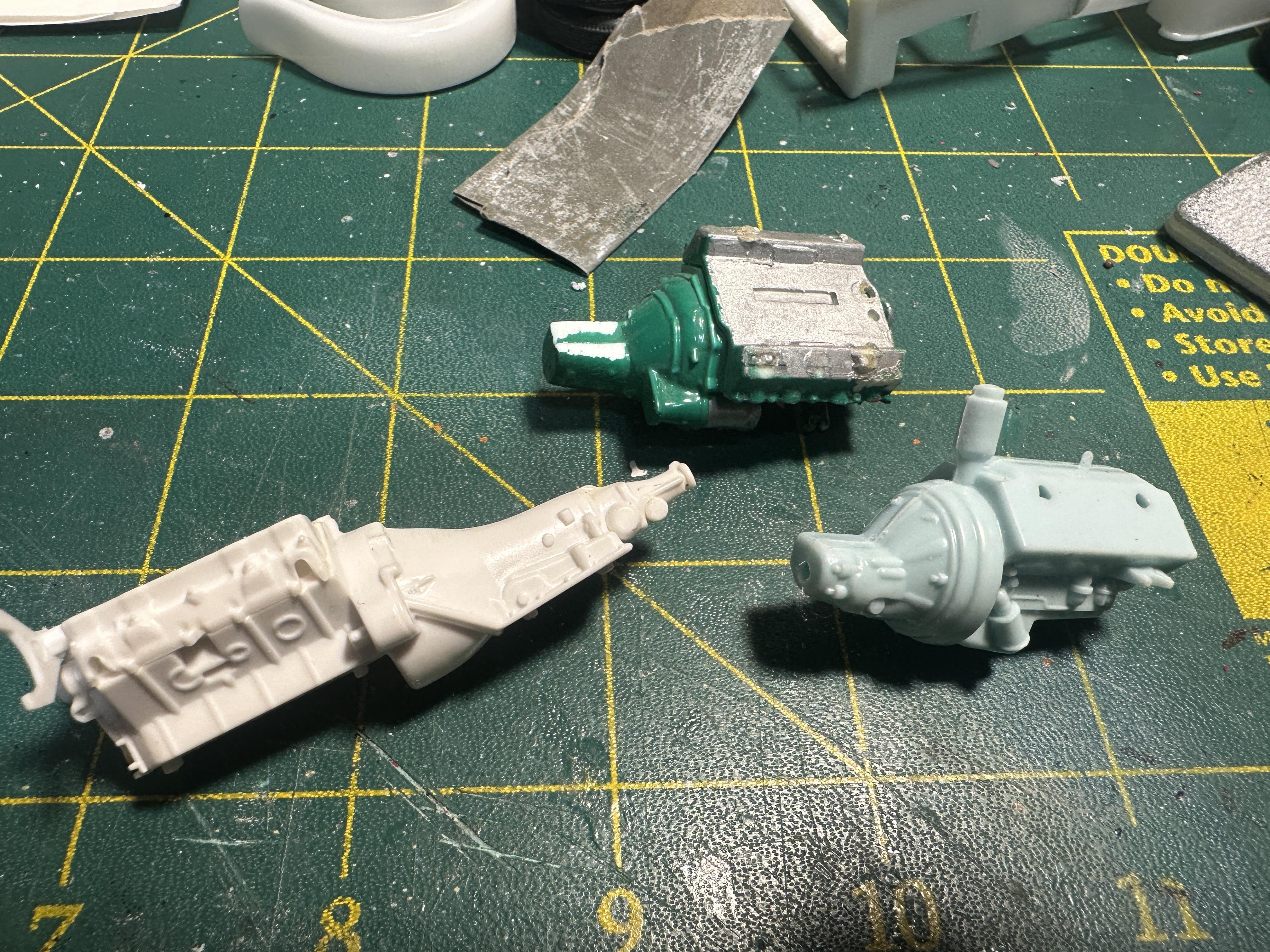
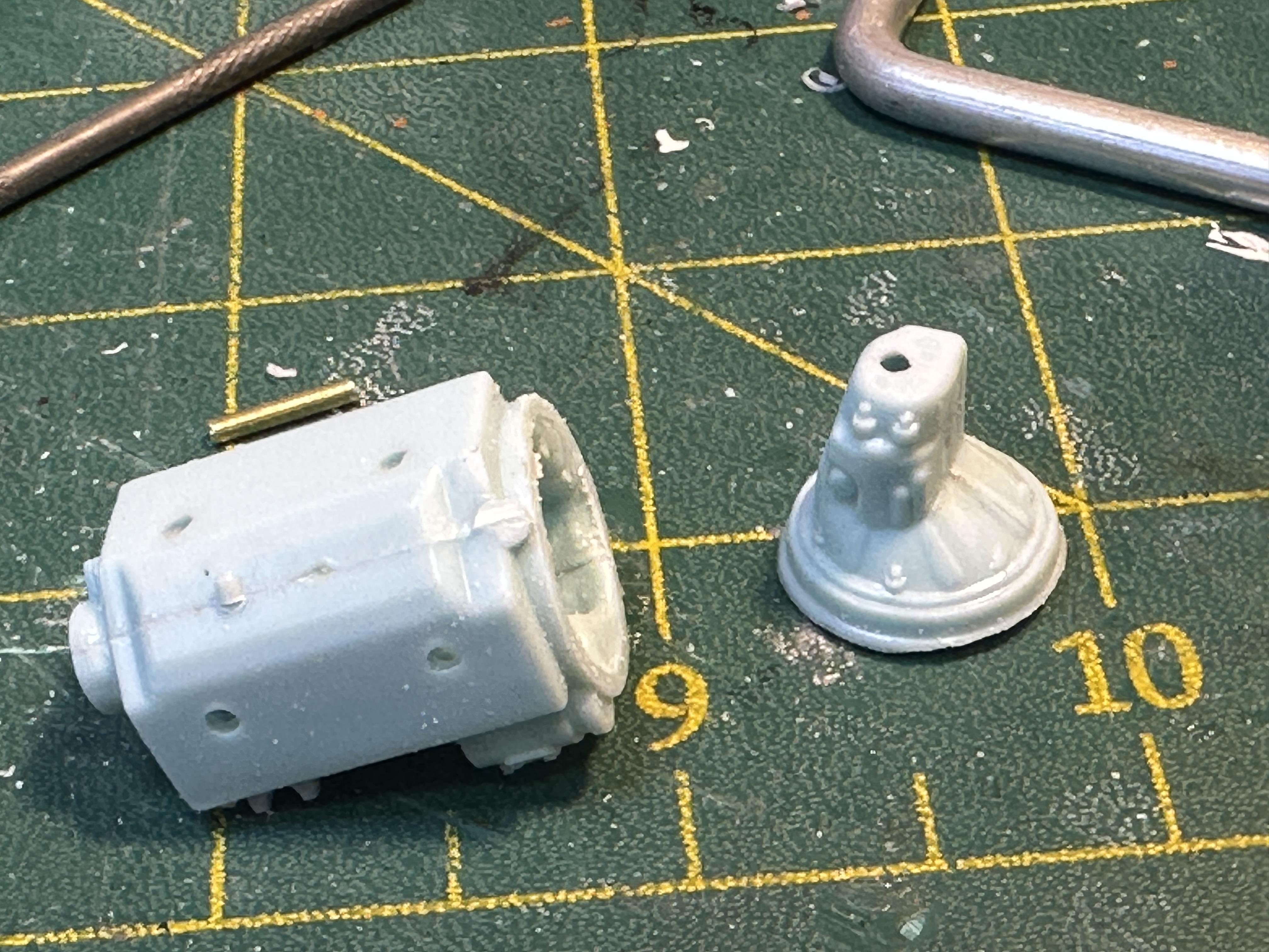
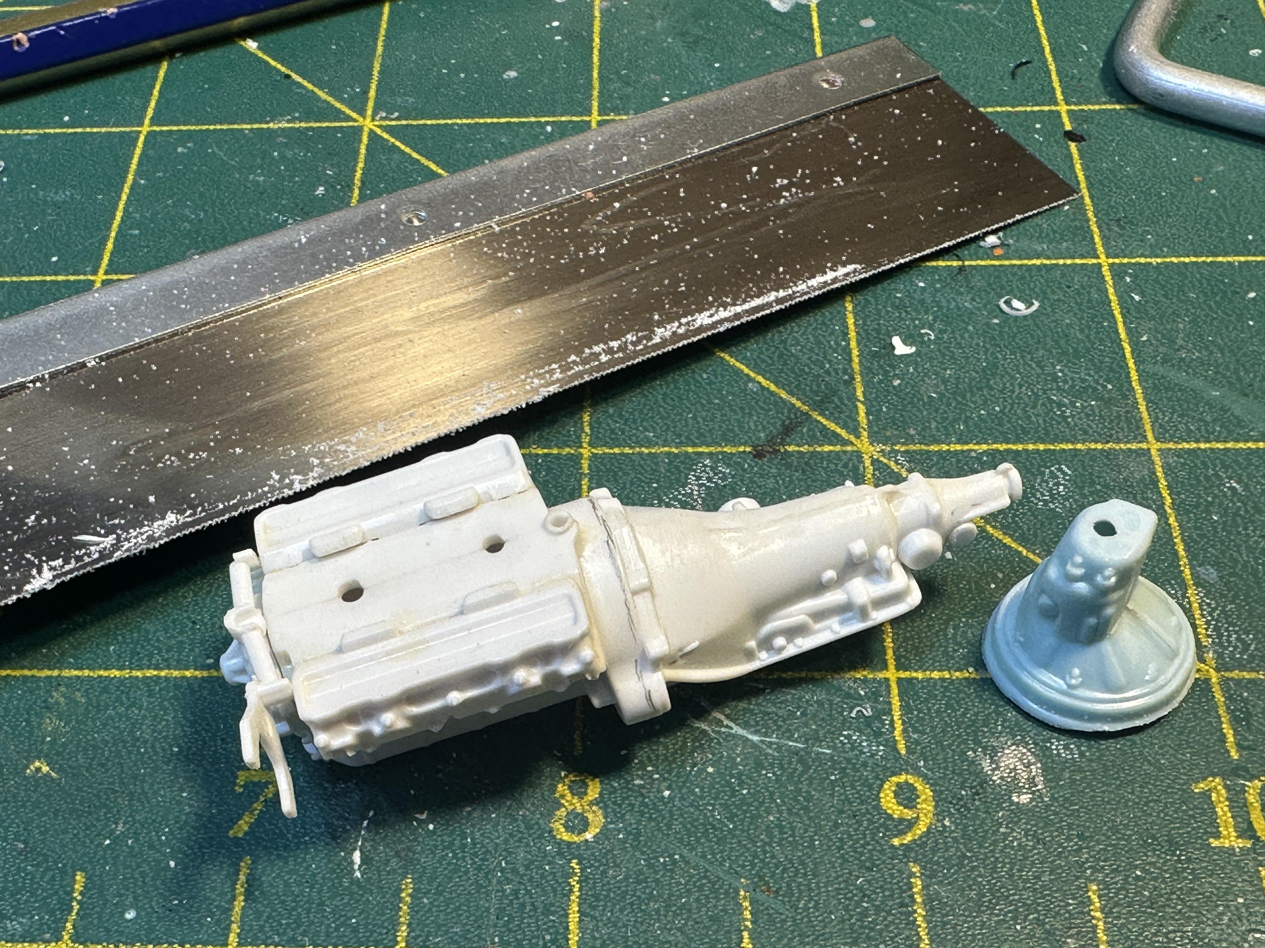
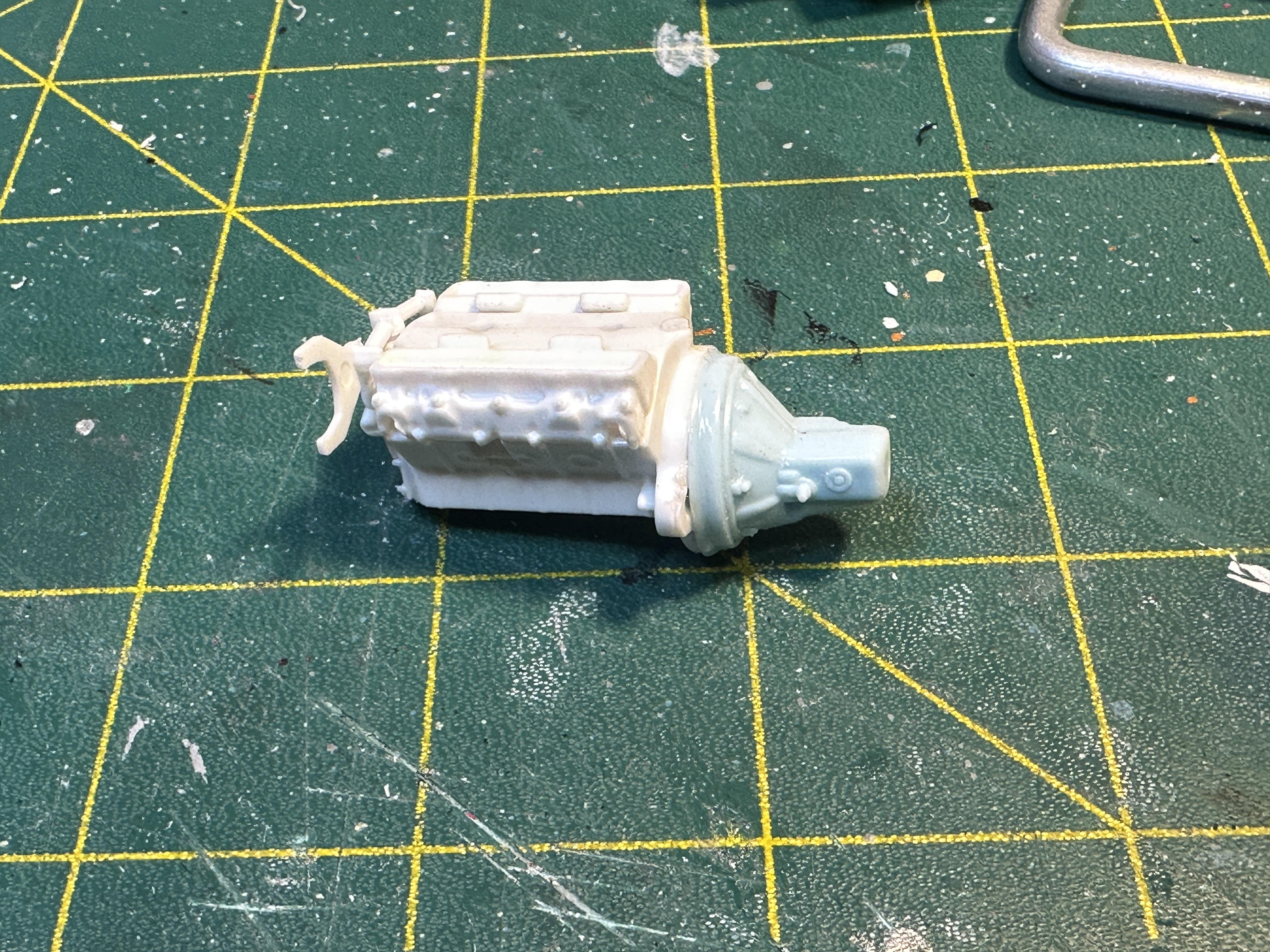
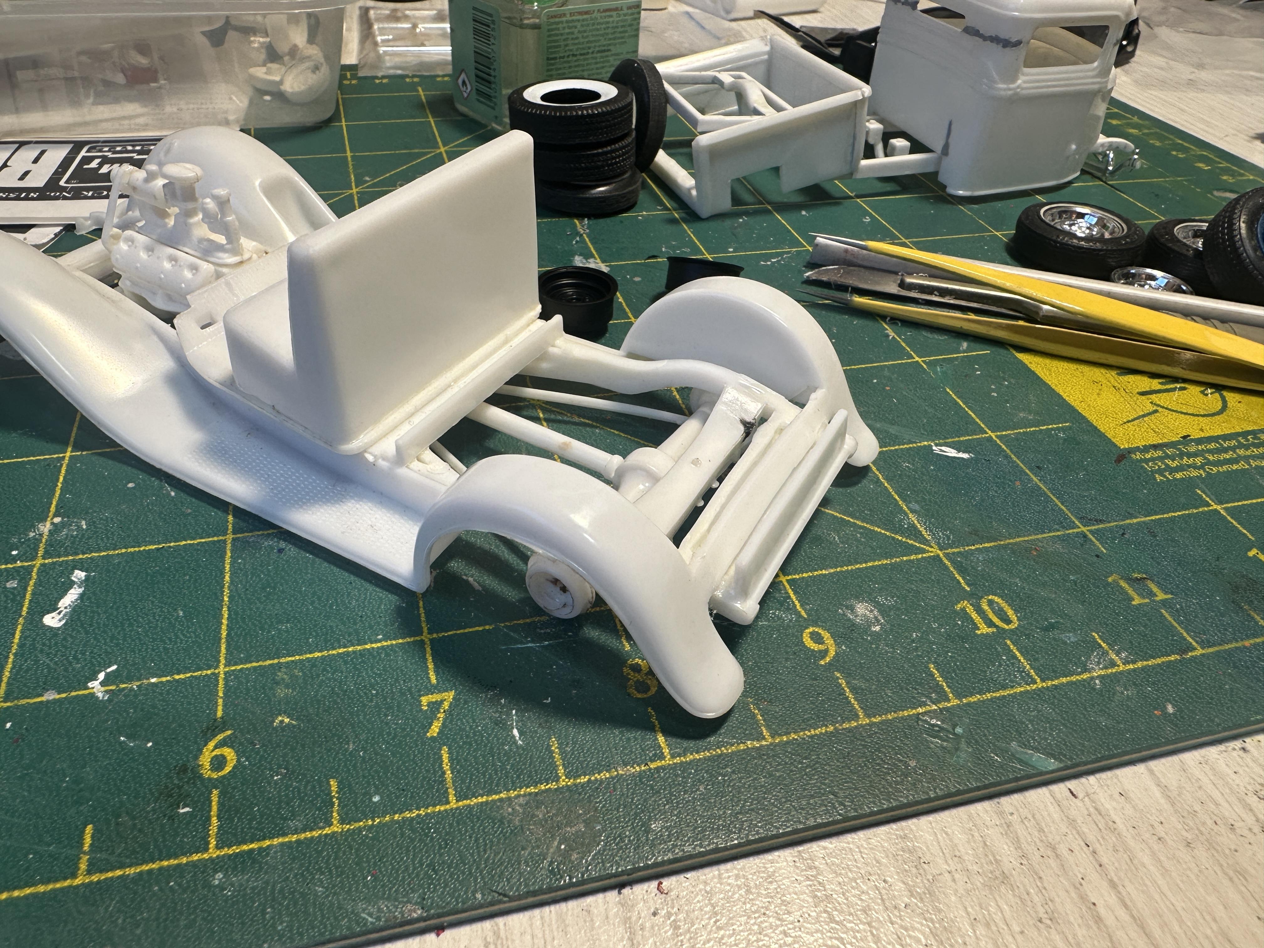
A thought was to use the PU as a tow vehicle for a recent build - just not so sure now after seeing it mocked up. A way low tow car ahead of a way high drag car. Be a sight to see on the road. And I have enough left over LMG metallic blue for the pickup too. This is what happens when you mix scales - coupe is 1/24th Before I put together the mock up the thinking was that the nailhead motor from the 29 roadster is still a good tow engine choice but the slush-o-matic was not. I needed a period correct gearbox choice - in the parts box is a nailhead from the AMT 40 coupe - aha it is a flat motor gearbox with an adaptor - just what I need. Some surgery called for. The green motor in the background is a Ford 427 with a flathead gearox. There were a lot of optimists back in the day - but flathead gearboxes were cheap then And now together. The centre crossmember will now need to be moved for the shorter motor combo And then when I cut that out I noticed a little twist in the frame A tweak and a breakage - the front cross member broke out. Well a chance to get it glued back together - straight this time. This may have been one of the reasons for shelving this in the first place I am going to carry on with this build - it may not become the tow vehicle but what a support car. Just imagine a race car with tow truck and entourage all decked out in the same colour scheme Thanks for looking
-
A wee mockup with intended tow vehicle. This would look unusual coming down the road. A way low rod with a way high drag car.
-
Thanks Tim I would have to say that you have some influence in some of my builds over the years. Your articles were always looked forward to in the various publications. It is a build that I have had in my mind for a number of years but things came together when I got the kit earlier this year and a bulk load of 32 and resin flathead parts of which there were three Ardun heads - it just all came together. I am sure we take influences from a lot of sources - magazines, shows and latterly online. As to an NNL meet - I would dearly love too but it would take some arranging, and I am getting on a wee bit too
-
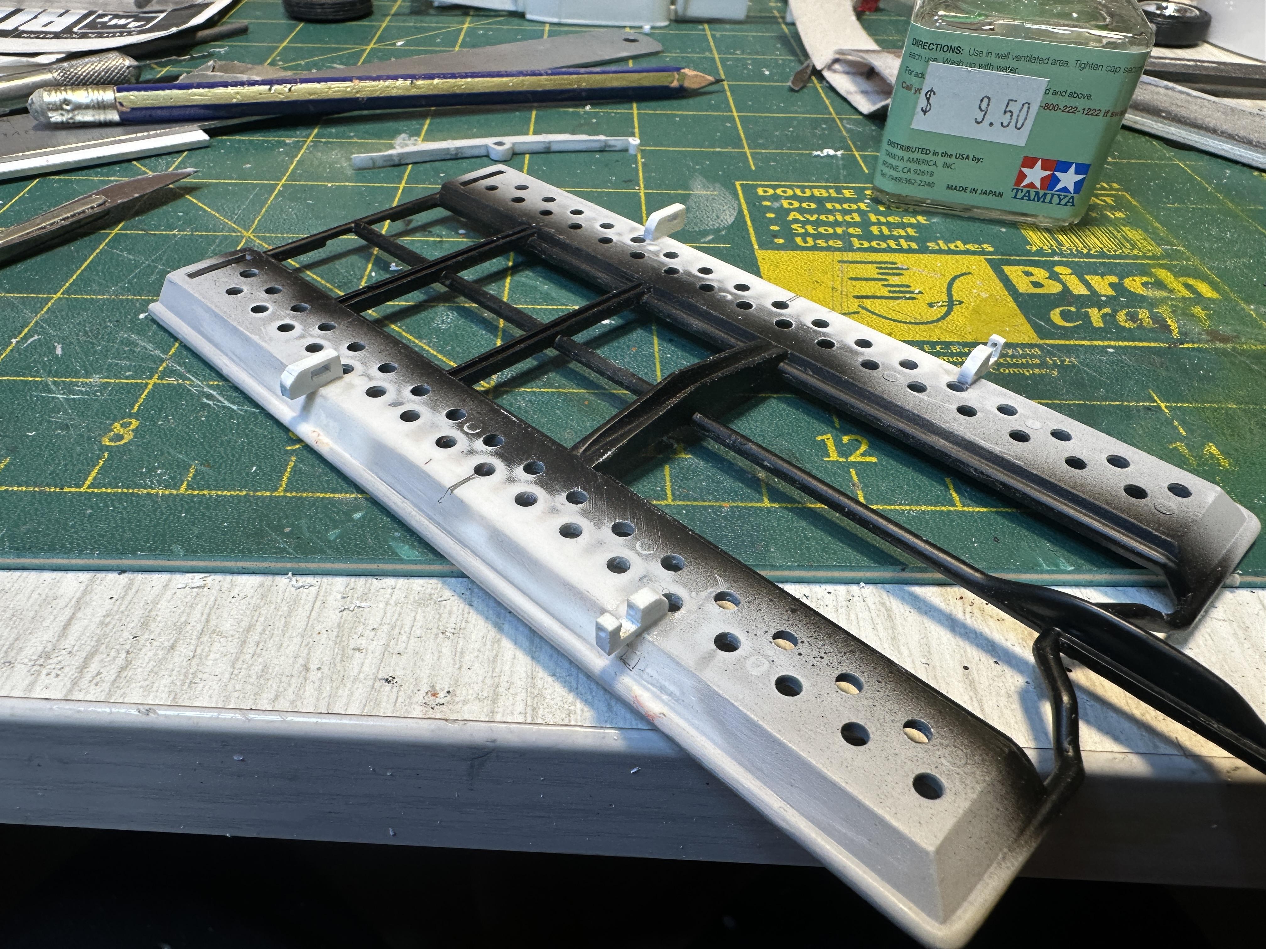
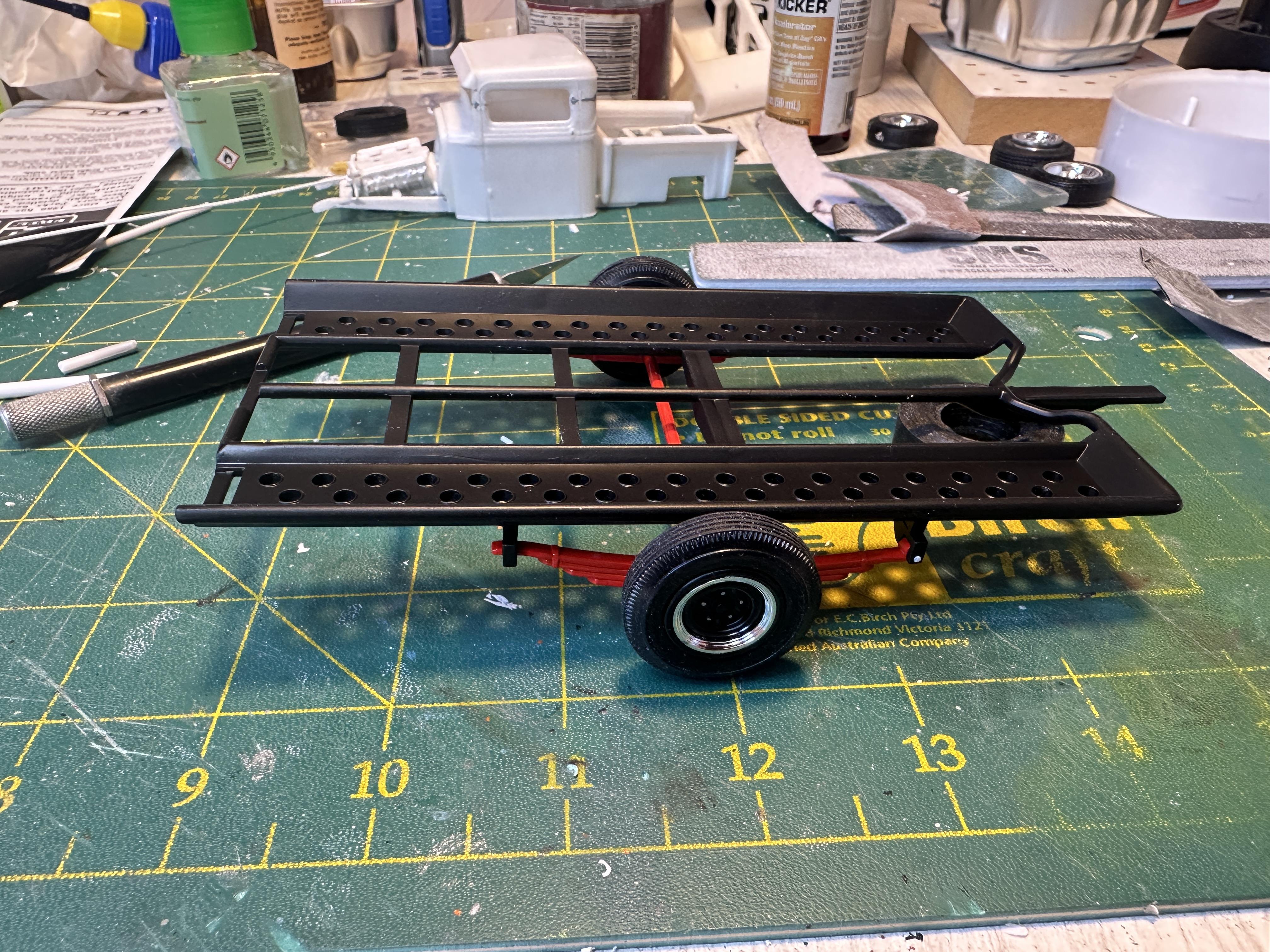
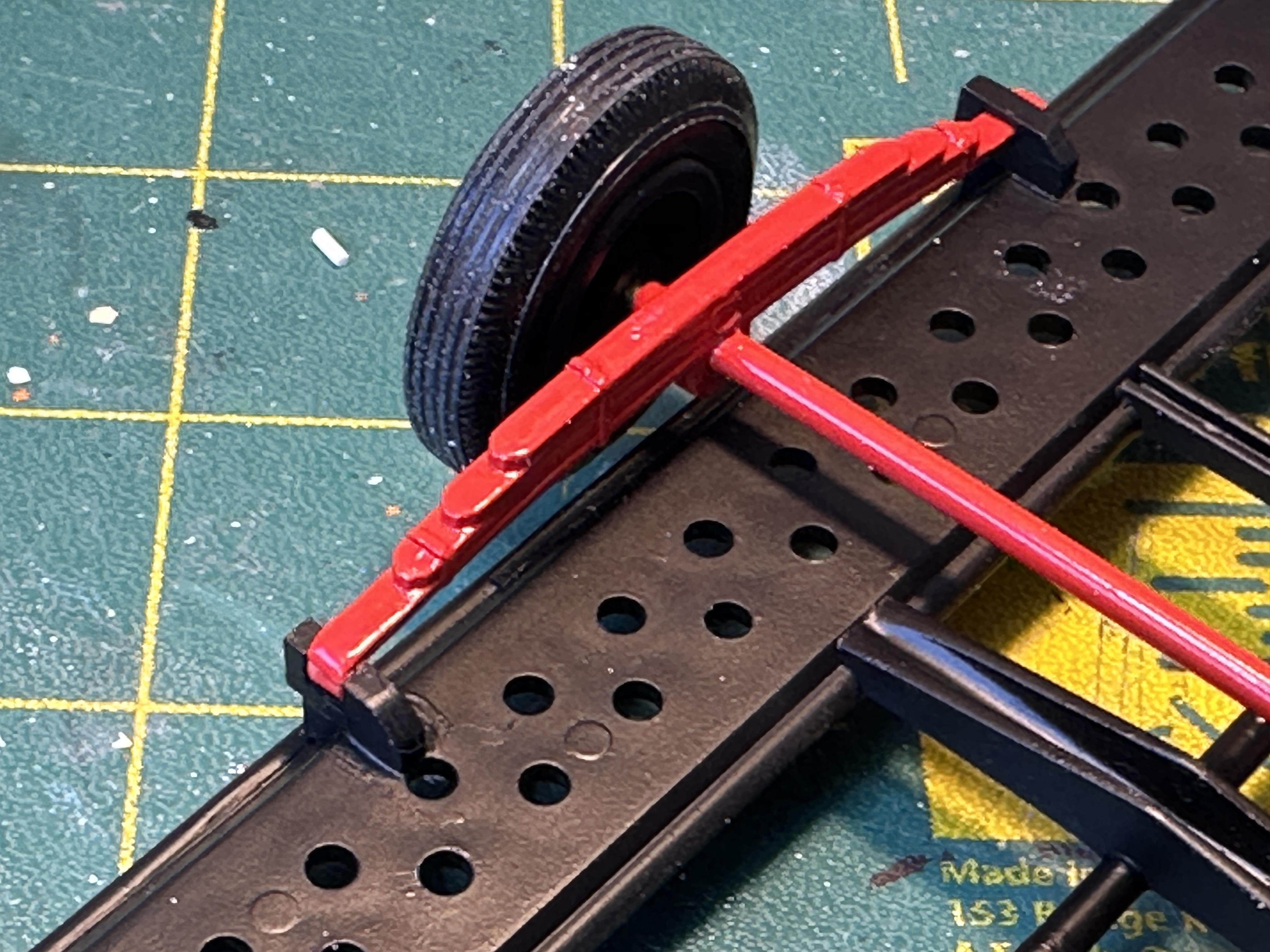
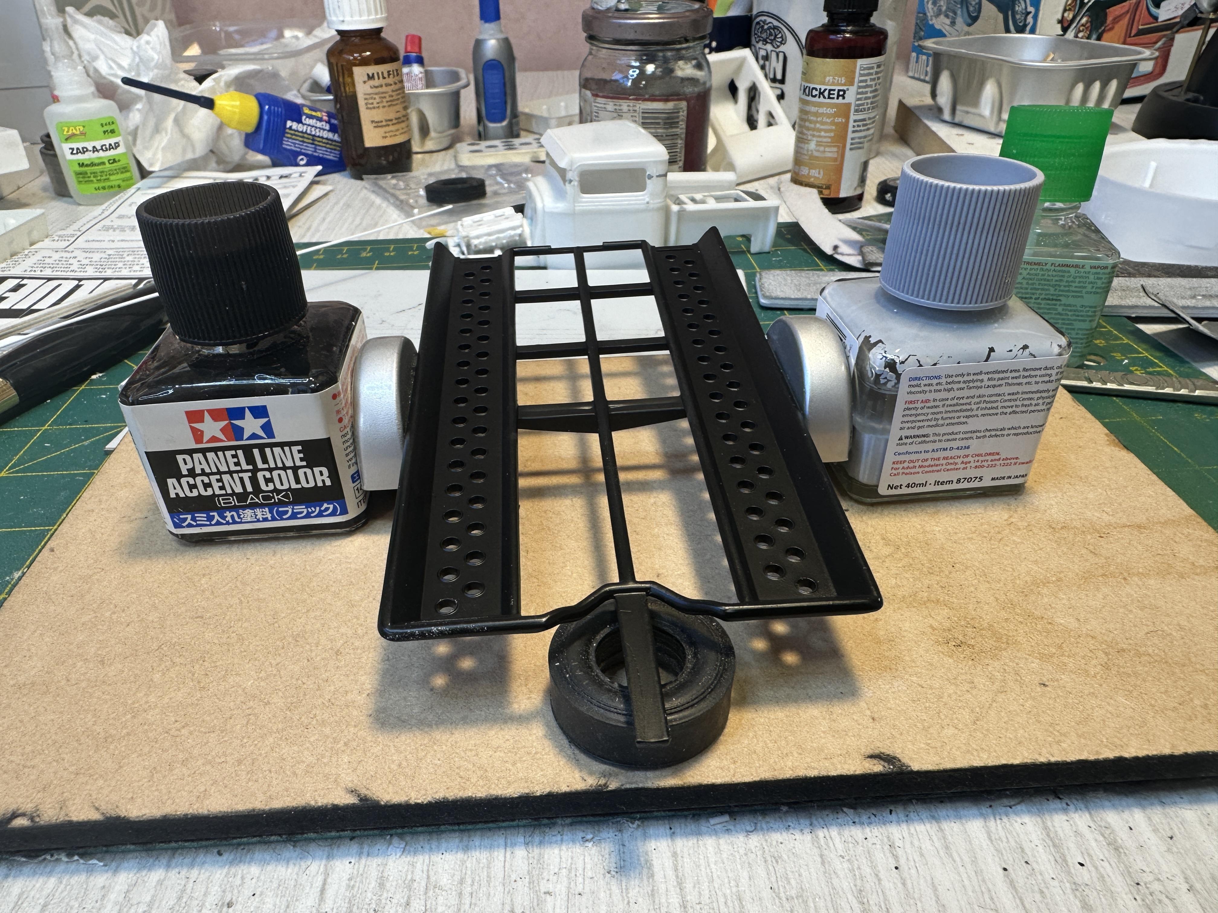
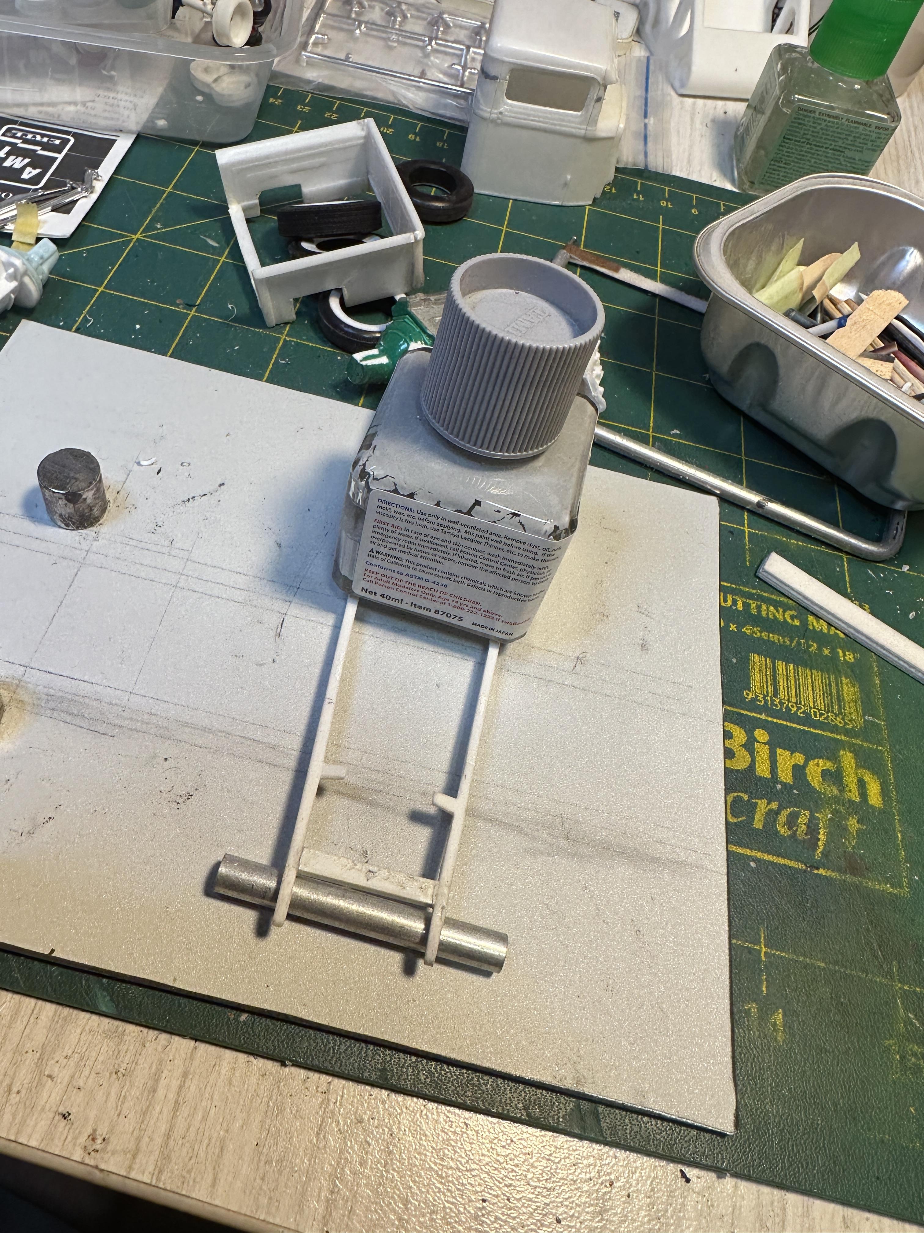
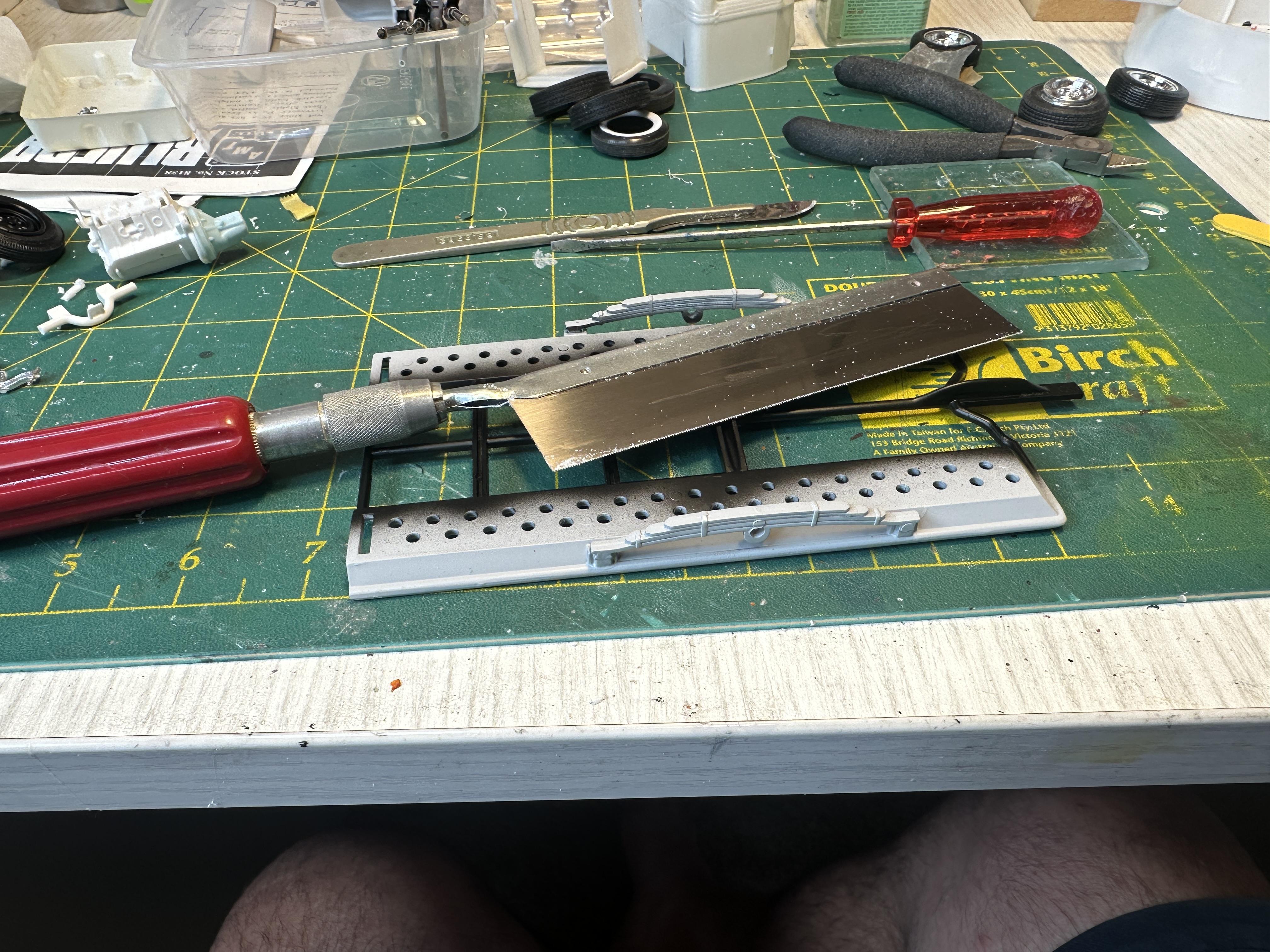
Well it is going to happen. The surgical tools are out. While the saw was out I was thinking of some guards even after looking at the video the @sidcharles posted where most trailers don't have them. I have a donor - the tow truck is not going to need the back guards so they got stollen. Will post a pix where guards are at next time Thanks for looking
-
34 Hot Rod Pickup
bill-e-boy replied to bill-e-boy's topic in WIP: Model Trucks: Pickups, Vans, SUVs, Light Commercial
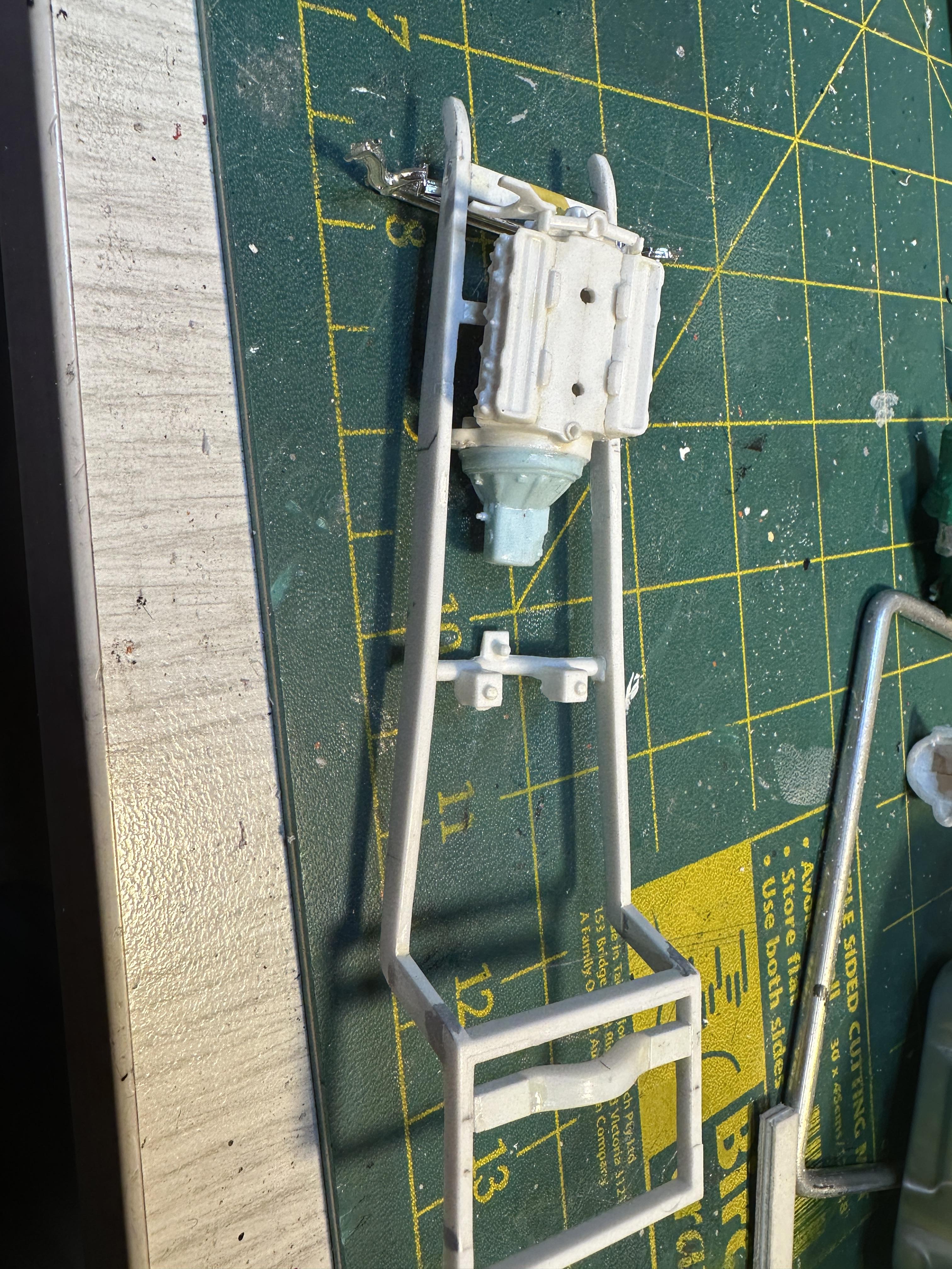
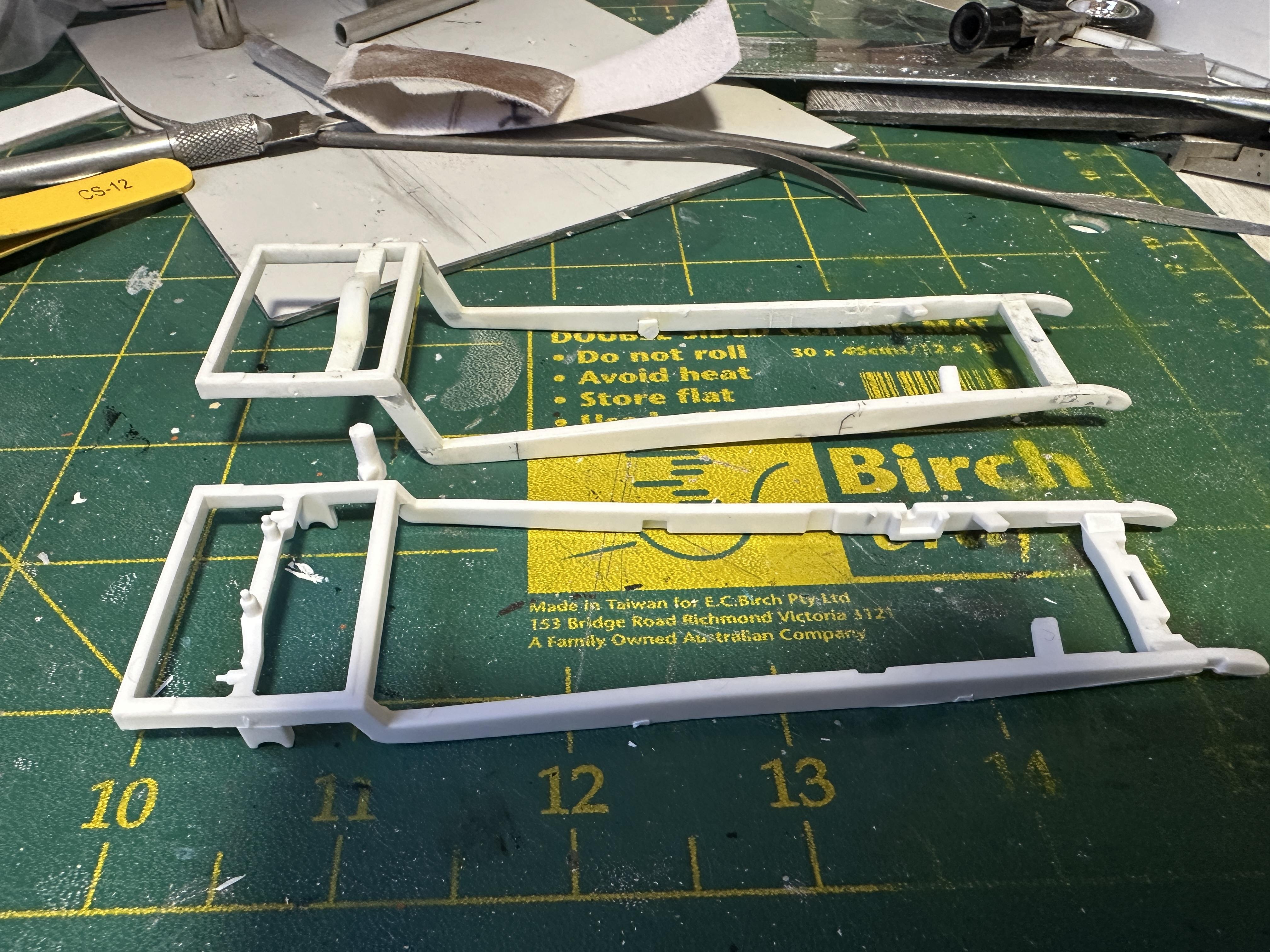
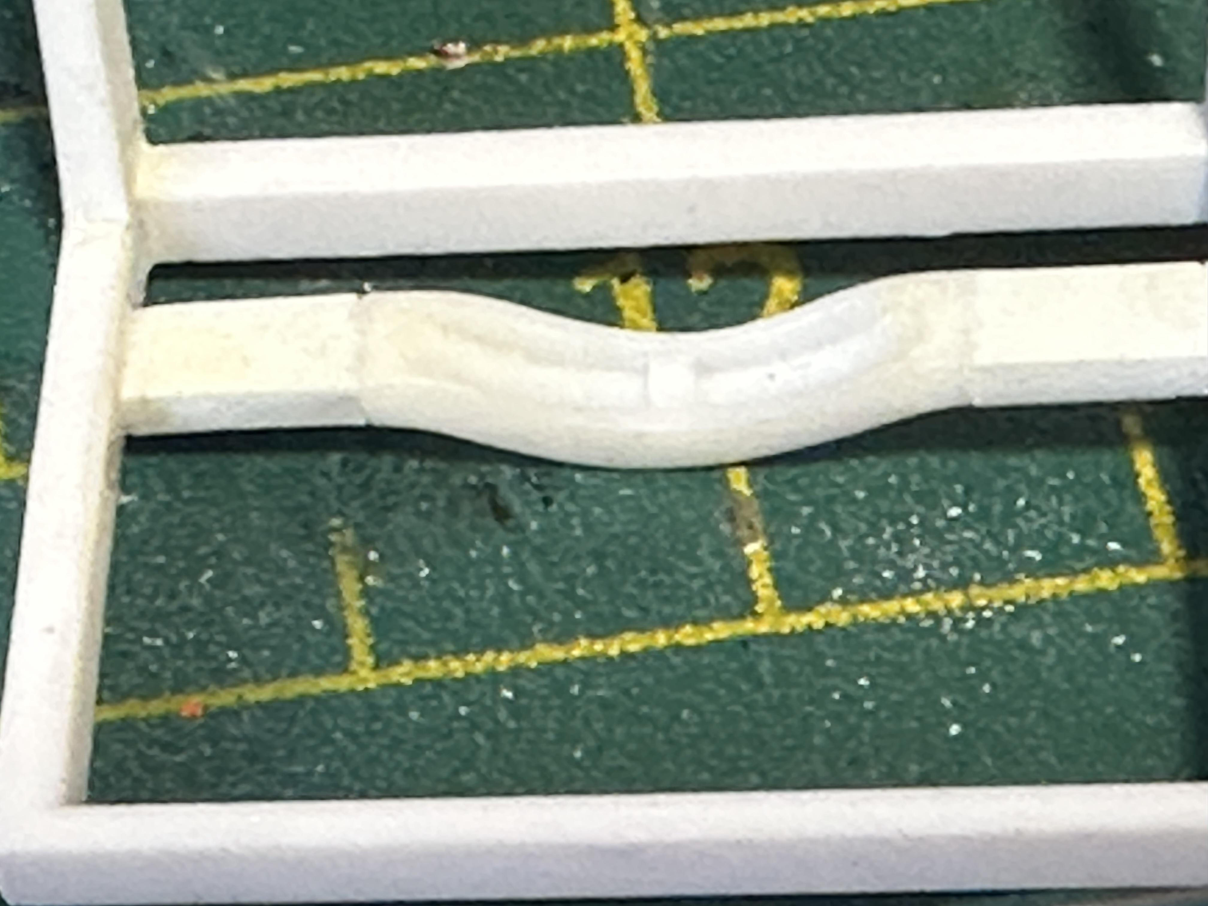
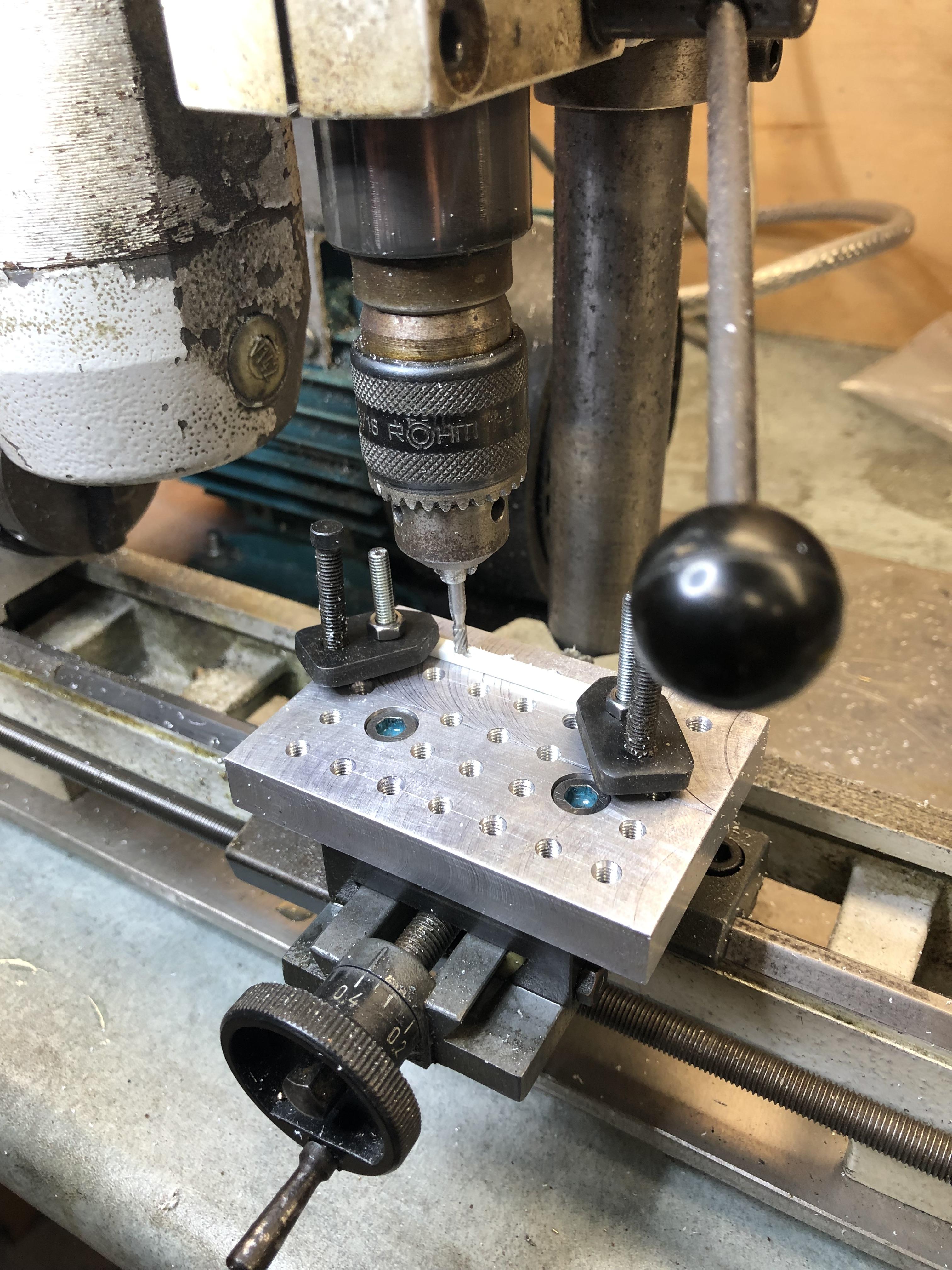
Moving on to the chassis. As can be seen in the first pix above the frame has a serious zed in the rear. The chassis started out as the Lo-boy version from a Revell 29 roadster. The Z has been pinned top and bottom for strength as there will be a lot of handling before the is completed. A comparison. Also at the rear the axle locating tabs have been removed and part of a Model A rear cross member added for a buggy spring and has been moved forward to have the spring above the axle - one of the reasons for the big Z The front cross member has been removed and replaced with a flat cross member to get as much lowering as I could with out resorting to other methods. It would have been easier to double pie cut the chassis at the firewall and closer to the front end to get the front of the car in the weeds but the flat cross member is enough I think. I made the cross member by milling a groove into a piece of rectangular bar stock And in the frame At this point the transmission cross member has been removed after being glued into place to accommodate a gearbox change. This will be moved forward. The pickup box has been shortened a fair amount as well. This mockup shows where this was headed when I started the build Un fortunately those narrow slicks got used in another build so moving to the big'n'little cross plies in the original pix Next post is where this is now headed Thanks for looking
-
Looking at it again I think your advice is sound. Thanks Craig I was wavering on whether to do this or not but I will. I have stripped the paint off and it now primed but it is never too late to change it .
-
I think it was in a box of bits of mostly AMT parts - mostly bits from when AMT kits were made down here in NZ circa 69-71. The Fireball was one of the kits available and I think it had a tandem wheel set from memory - this will be single axle
-
I checked the link - I am a sometime lurker on that forum - it is way cool
-
34 Hot Rod Pickup
bill-e-boy replied to bill-e-boy's topic in WIP: Model Trucks: Pickups, Vans, SUVs, Light Commercial
Boom, boom😀 -
A very humble thank you to all for the kind words. It is quick simple builds like this that turn out OK that keeps the flame going. And I dare to be different sometimes. Thanks
-
34 Hot Rod Pickup
bill-e-boy replied to bill-e-boy's topic in WIP: Model Trucks: Pickups, Vans, SUVs, Light Commercial
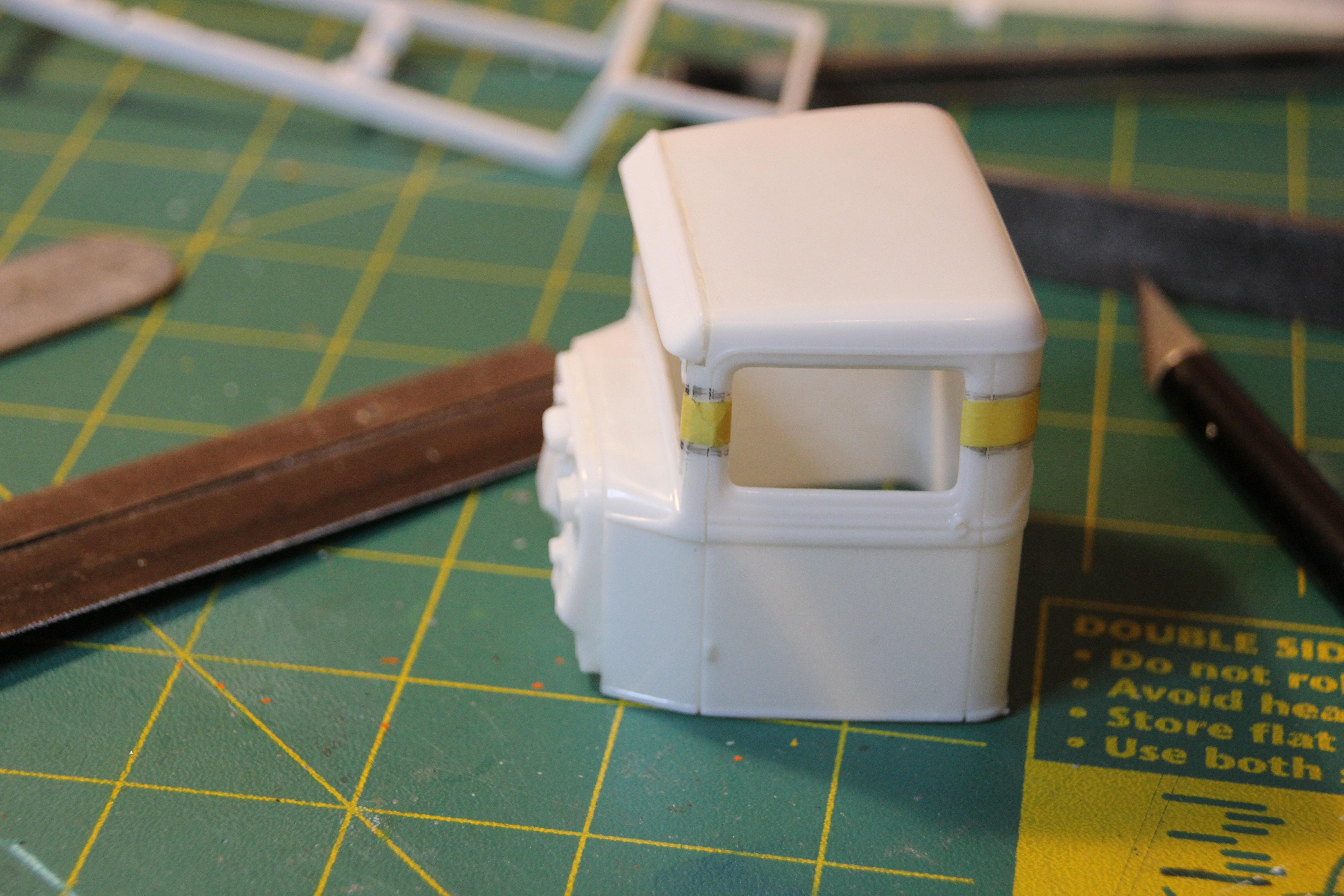
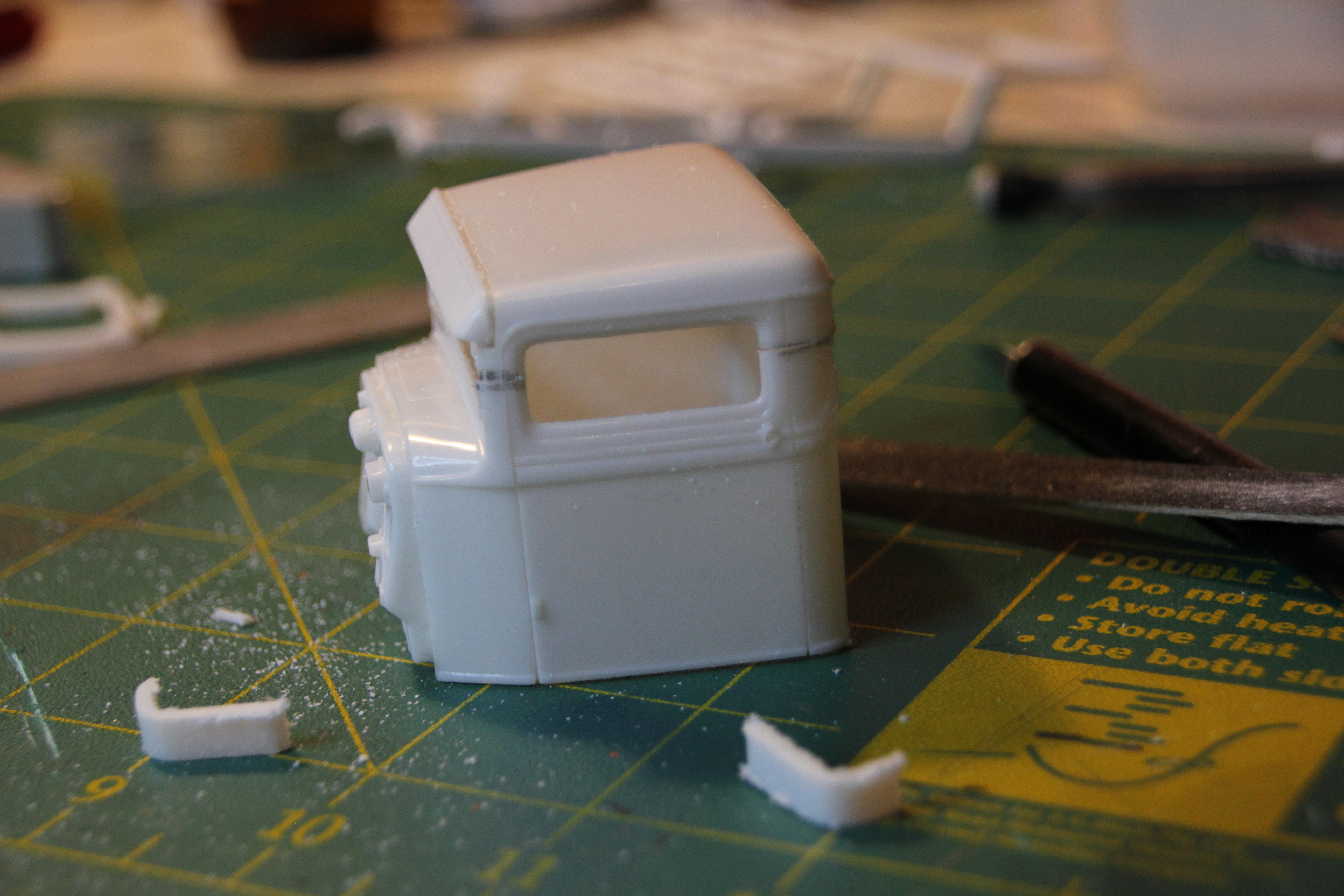
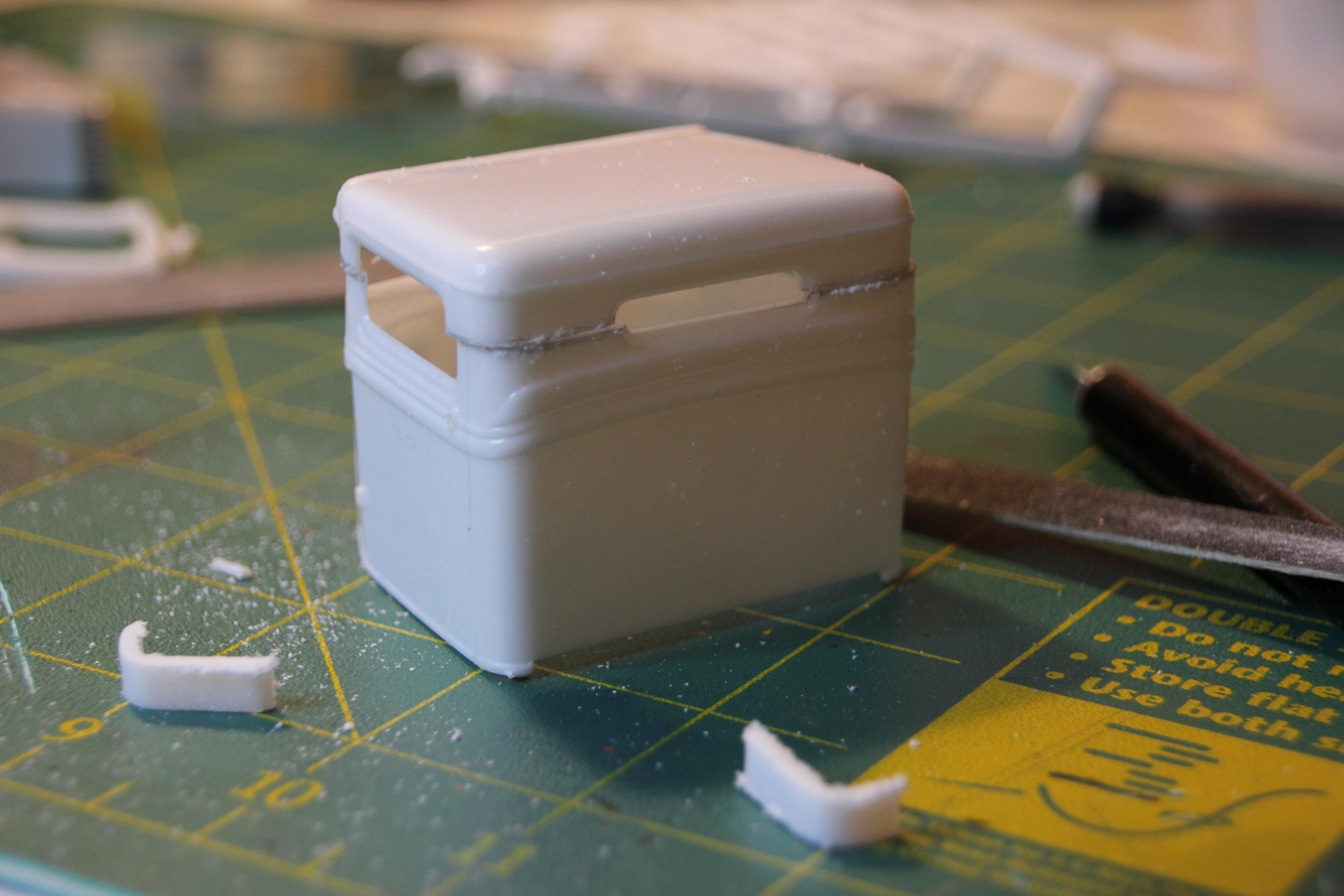
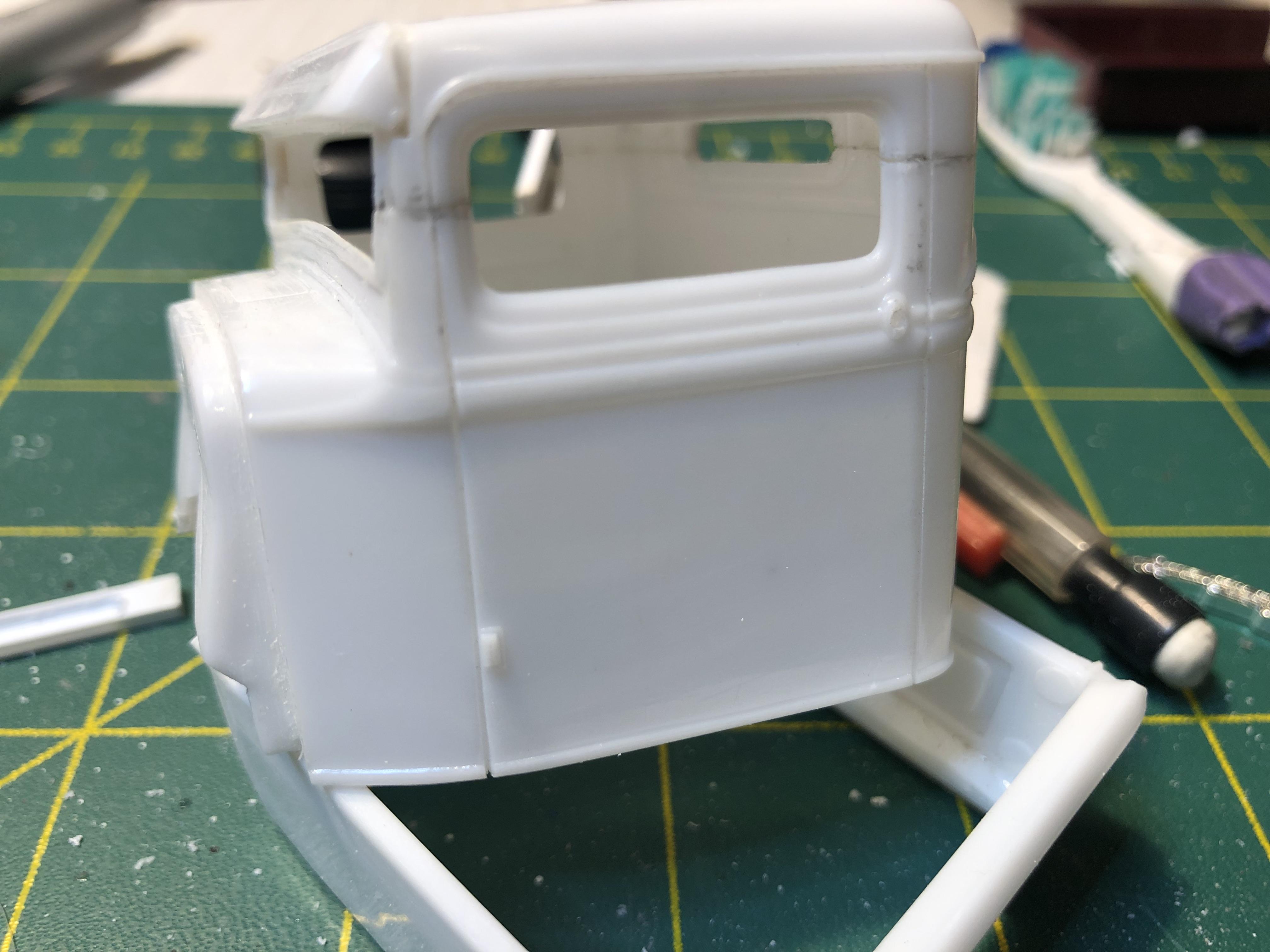
In the beginning - Getting ready for chop - at least 4" marked off with masking tape Next up with the top chopped and ready to be glued back together. The 34 PU is a simple chop as all the pillars are straight up and down, not like the cars where the A pillar is raked back a bit And glued. Next installment - chassis works Thanks for looking
-
What a beautiful car. All the right bits in all the right places, spot on chop height, stance etc. Like it
-
Or this might be betterer methinks - dragged it off the shelf. Build was started way back in 2018. New topic started under Pickups Every thing period correct - Nailhead, big'n'little cross plies, Model A front axle, older rear axle - unfortunately out of quickies, sever chop n channel, zedded rear - keep an eye out of at the build thead
-
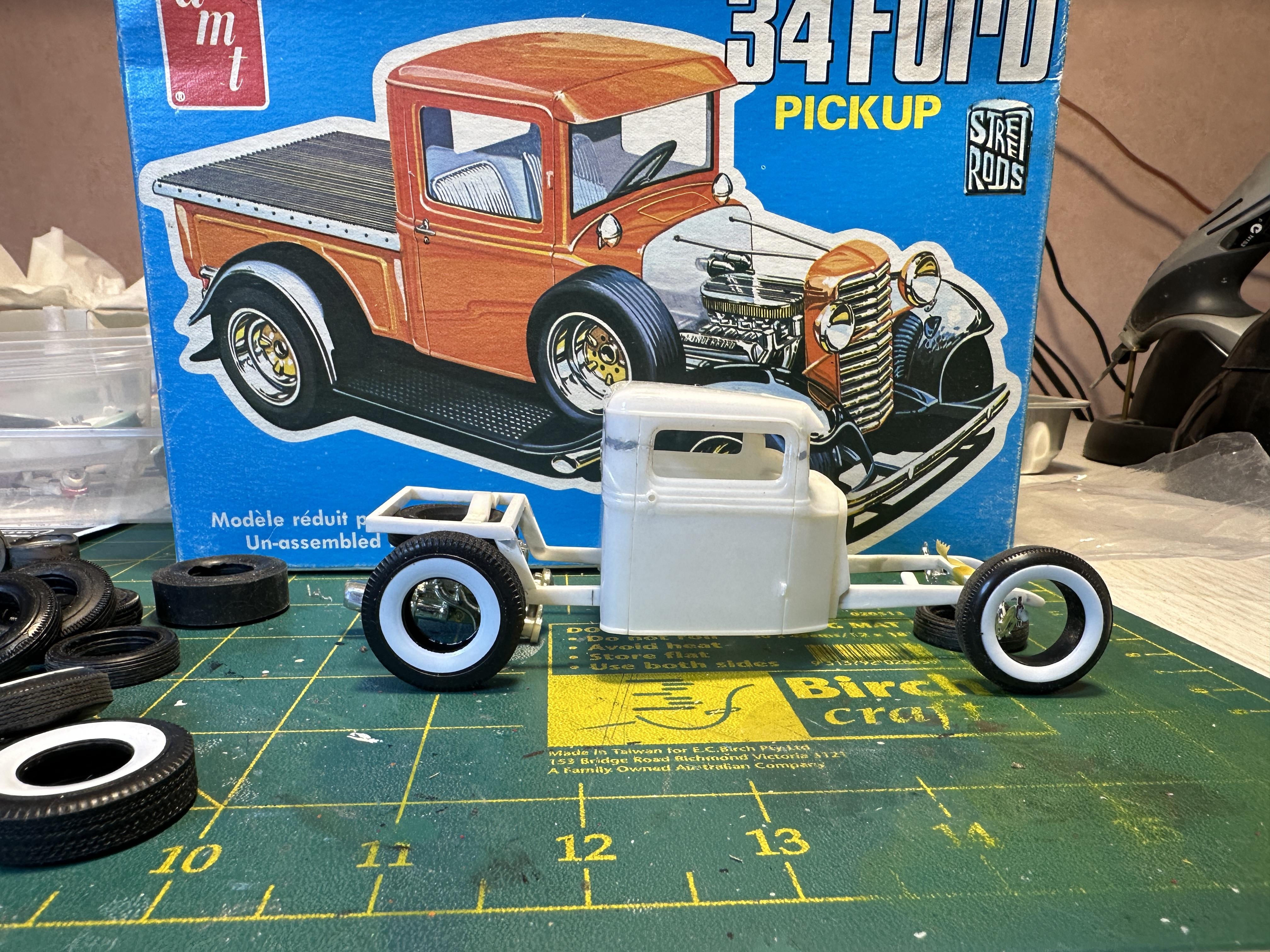
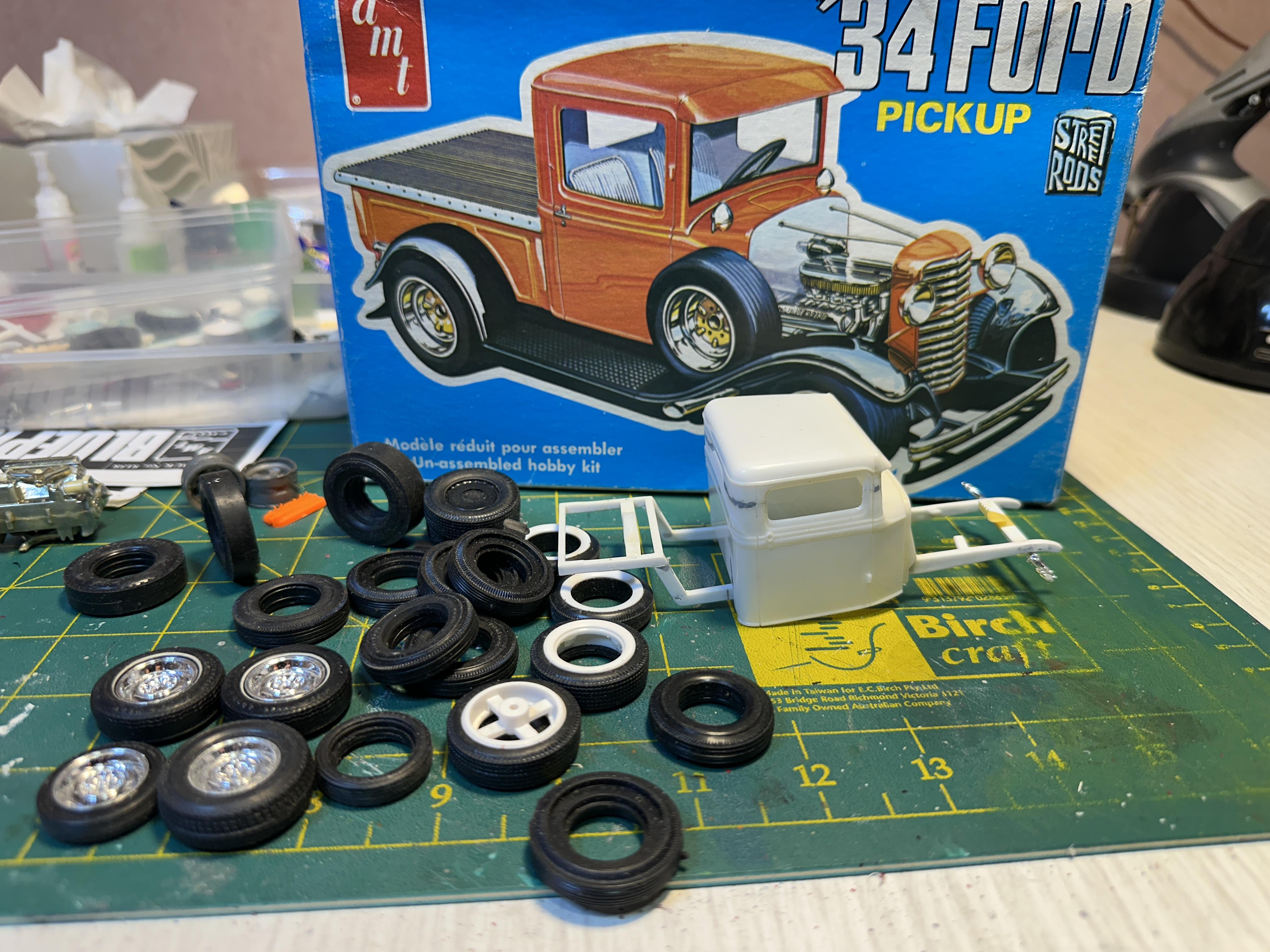
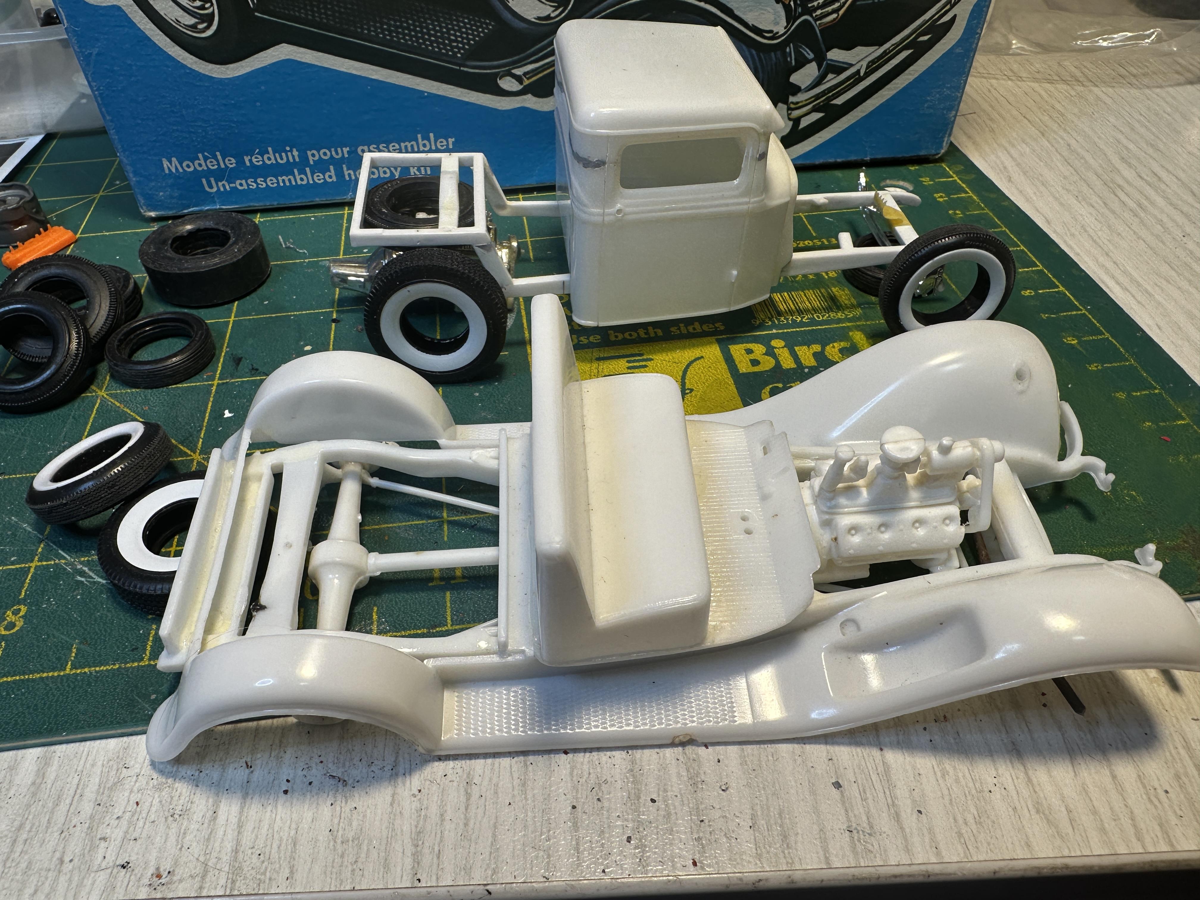
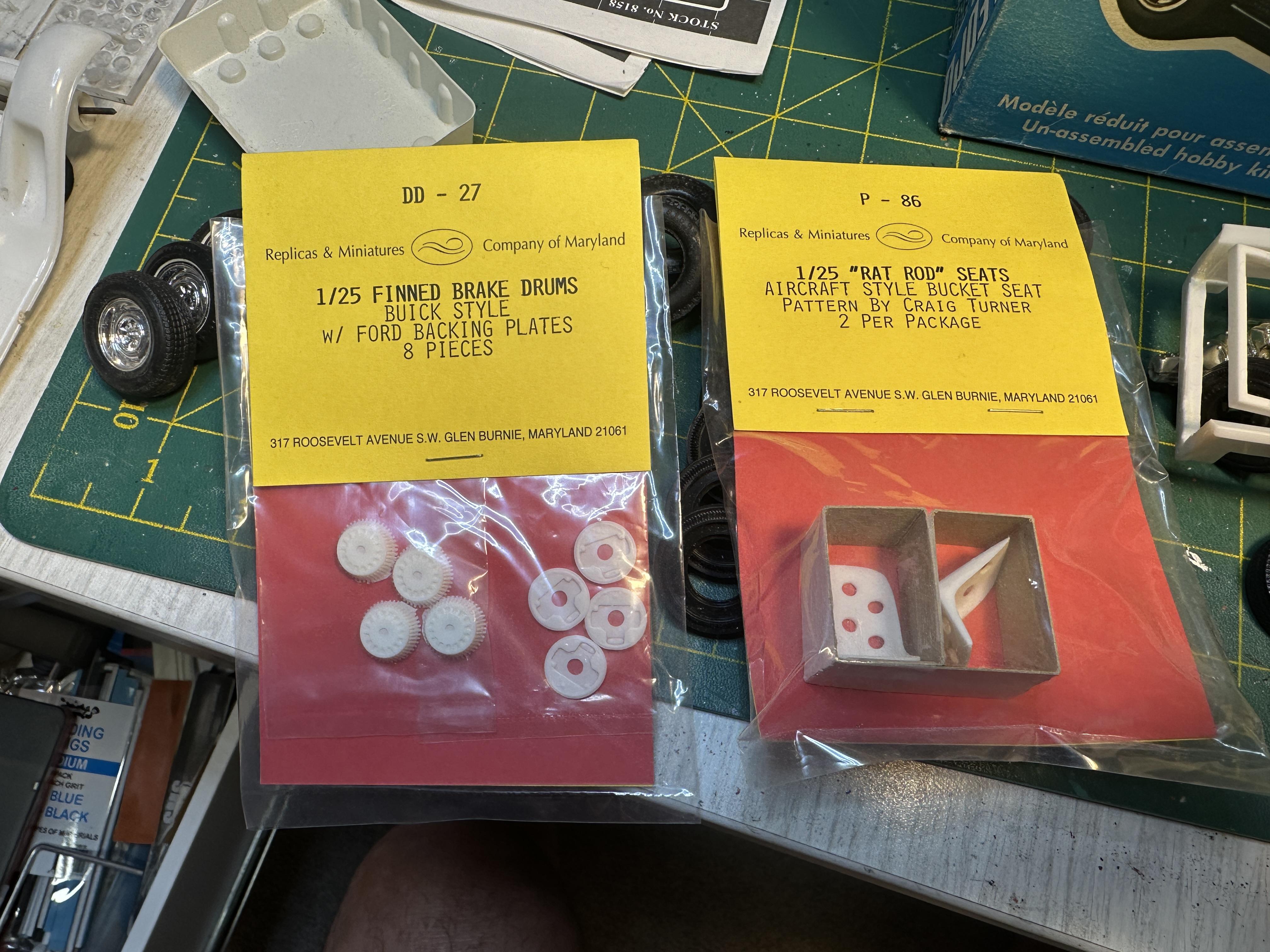
Looking back at my photos of this stalled build the chop was done way back in August 2018 and the photo spread was over the subsequent 2 years before it got shelved. The build started with an unpainted partly built AMT 34 PU glue bomb. The build is one I have always wanted to do but was put on the back burner as the 34 PU was not available for quite a few years and at that point I only had the one unbuilt kit so it stayed in the stash. Things changed when Lindberg somehow got a hold of the old AMT moulds. Then along came the glue bomb so my old unbuilt can stay squirreled away for another day. They are low quality kits IMO anyway so it will most probably stay there. I have just finished my Model A Bange build so I thought it would be a good idea to bring this off the shelf. I did a quick look through the boxes and there are parts from the 34PU, Revell 29 A roadster, a Revell Model a PU and some other bit from the parts box A quick mock up of where this is at - There was so many tires in the boxes, big'n'little, wide whites, narrow slicks. The build note originally has skinny cheater slicks but they got used on another build. So the thought is now wide whites - rears from a Moebius 56 300B and the fronts from the parts box - not sure where they came from The chassis is the Hi-boy from a Revell 29A Roadster with a massive Z in the rear. Body has a 4" chop and is channeled deeper than the frame rails Compared to the original clunker And I found these gems so will definitely be using these too. Next couple of posts I will put up pix of the build. It will be a good memory jogger as there has been quite a bit of work done to get this far. Thanks for looking
- 20 replies
-
- 11
-

-
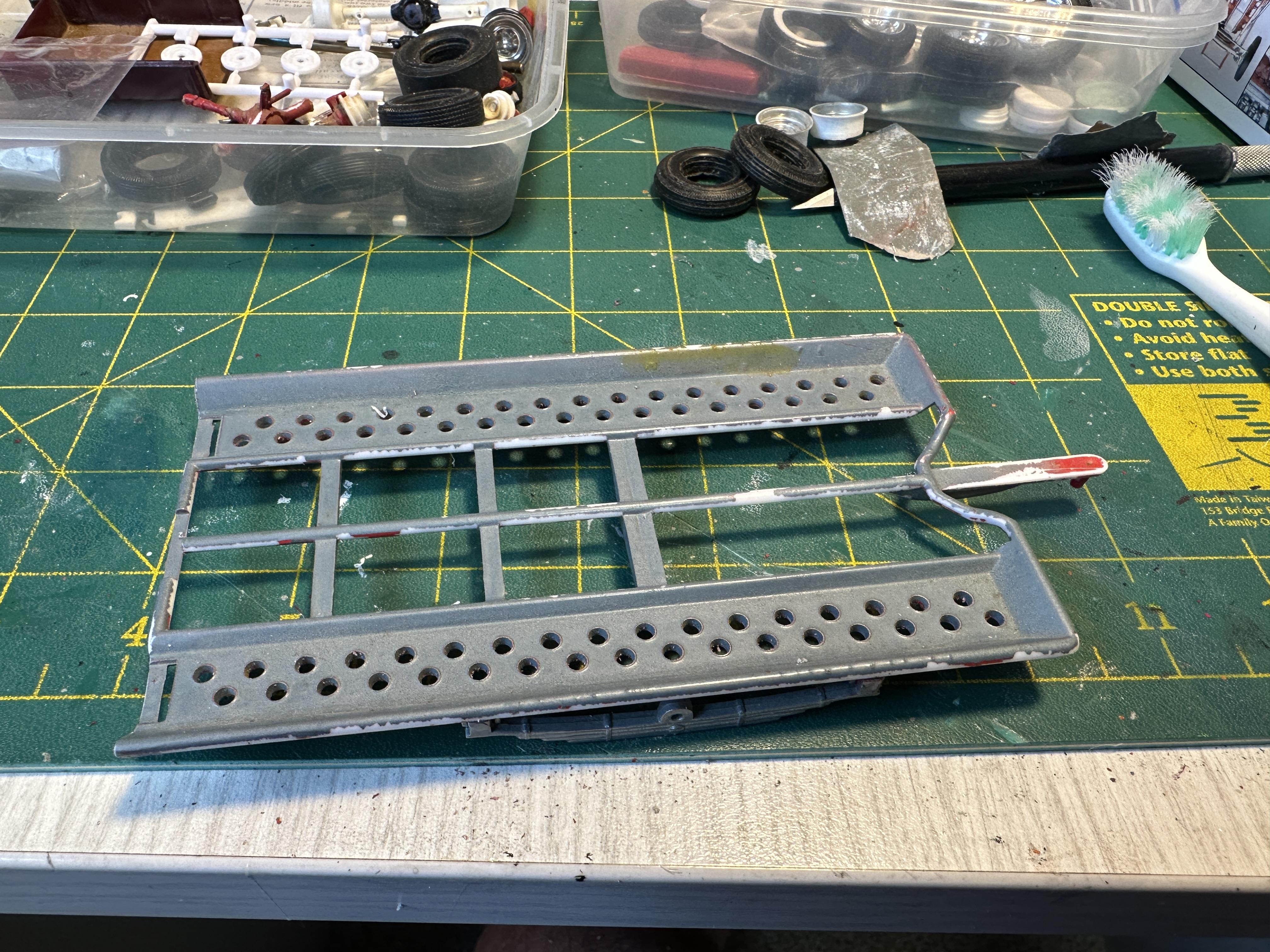
Just when you think you are done @Bullybeef releases a whole bunch of his bench squirrels down my way. Looking through the parts boxes of a stalled build and come across this. Now every race car needs a trailer. Not sure of the origins as I think it came with a pox of parts that was given to m many moons ago. I think it is AMT and more than likely to be as most of the parts in the box were AMT. In the purple pond at the moment. And I suppose I will need to find a suitable tow truck from the late 50's - early 60's to haul this lot around. A 53 F100 springs to mind first - I have never built one of those before
-
Thanks guys. Means a lot
-
Just a bit of inspiration😁
-
Nice rod. Don't see full chassis depth channel very often - well done