Snake45 Posted March 5, 2019 Share Posted March 5, 2019 Looking good! GITTER DONE! Quote Link to comment Share on other sites More sharing options...
Straightliner59 Posted March 5, 2019 Author Share Posted March 5, 2019 7 hours ago, Snake45 said: Looking good! GITTER DONE! Thanks, Snake! I'm on it! Quote Link to comment Share on other sites More sharing options...
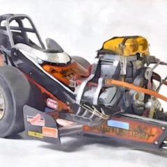
Straightliner59 Posted March 7, 2019 Author Share Posted March 7, 2019 (edited) Feeling like I should take a day or two away from this, as each time I make progress, it seems that I have to fix something. Case in point: Although I'd installed the engine, motor plate, torque tube, bellhousing and differential many times, and they'd always fit, as soon as I was ready to install them permanently, suddenly, I was about 1/32" long. Don't know where it came from, as noting had changed. I broke the steering support off the chassis, so, it needs to be reattached, as soon as I am finished with the new steering box (when I found the old one, it looked great, but, somehow, back in the "sands of time", apparently, I'd cut or sanded something cattywompus, and I didn't like it). I can't say how many times I've reattached the oil filter and its assembly. Anyway, I am frustrated. At the same time, I still find myself drawn to the thing, so, perhaps my break won't happen. I am very happy with those Enderles! They really make this thing look the part of a junior fueler. Once the manifold's done, and plumbed, and the stacks are painted, and linkages installed, that assembly will be the crown jewel of this project. My friend, Guy asked if I was going to even up the stacks. Fret not! They're just sitting up there, not even tacked. I just wanted to see how it all looked, together. Just in case you missed the photos on the "Get 'er Done" thread, here's very much what the finished dragster will look like. Qs and Cs welcome, as always! Hope you guys like it! Edited March 7, 2019 by Straightliner59 Quote Link to comment Share on other sites More sharing options...
Scott8950 Posted March 7, 2019 Share Posted March 7, 2019 very nice work... Quote Link to comment Share on other sites More sharing options...
Straightliner59 Posted March 7, 2019 Author Share Posted March 7, 2019 Thanks, Scott! Quote Link to comment Share on other sites More sharing options...
Straightliner59 Posted March 10, 2019 Author Share Posted March 10, 2019 (edited) Working on the steering butterfly. The wood will be smoothed, and sanded to a hand grip shape. The brass pins will be cut down, sanded flush with the wood, and polished. The photoetch is an old Garage Scenes piece... Edited March 10, 2019 by Straightliner59 Quote Link to comment Share on other sites More sharing options...
Snake45 Posted March 10, 2019 Share Posted March 10, 2019 43 minutes ago, Straightliner59 said: Working on the steering butterfly. The wood will be smoothed, and sanded to a hand grip shape. The brass pins will be cut down, sanded flush with the wood, and polished. The photoetch is an old Garage Scenes piece... Wow! I watch them do this almost every week on Forged in Fire, but you're doing it in 1/25! Quote Link to comment Share on other sites More sharing options...
Straightliner59 Posted March 10, 2019 Author Share Posted March 10, 2019 35 minutes ago, Snake45 said: Wow! I watch them do this almost every week on Forged in Fire, but you're doing it in 1/25! And, here it is, all done. I used super glue to bond everything together. There's no finish on the wood or brass, it's simply polished. Quote Link to comment Share on other sites More sharing options...
Straightliner59 Posted March 14, 2019 Author Share Posted March 14, 2019 I made a windscreen from aluminum, but, I am still considering a plastic as well. Either way, I'll need some way to attach it to the cowl. Since they were generally riveted, I thought I'd see how I could do something passable, since I don't think making brass rivets of the size I need is a realistic expectation! In one of my drawers, I have some tiny Grandt Line plastic rivets. They are a bit out of scale, but I think they'll work. Here's what I did (experimentally--I haven't applied it to the model, yet). I laid two sheets together, and drilled a single hole through both layers (research said that it's best to drill and rivet one at a time to make life easier!). I then removed one the rivets from its sprue, leaving a long section of the rivet's shaft and inserted it through the hole. Then, it was merely a matter of swaging the end, to mushroom it against the sheet. I used a lighter, and just kind of waved it at the rivet. A soldering iron would work, as well. Rivets could very easily be made using stretched sprue. If the Grandt Line rivets look too large to me, I may switch to sprue rivets. I am interested in comments regarding whether you think plastic, or the aluminum windscreen would look better. Also, what you think of the rivet idea. There is also a photo I call "Frankenstein Vs. The Giant Arachnid." And, just for the fun of it, I'm going to throw in a pic from March 13, 2009. A decade of thrills! I was laying out the motor plate for the body you see here,as I was putting together an article on building dragster bodies from aluminum, for the old SLM website. I have since built another, the current cowl (the project's third). Lastly is a photo of an experiment using Wright's Silver Cream (Shout out to Snake for the heads-up) and a cut-off toothpick to create an engine-turned effect. I arbitrarily chose a number of turns on the cross slide knob (clearly, too many, once I washed it, and could see the result) and used the Dremel drill press. I'm looking for a reliable method of engine-turning, using the things I have at hand. I think this will work, as the silver cream (which, I assume, is some sort of jeweler's rouge) allows the toothpick to gently abraid the surface of the metal, without fraying the toothpick too severely, due to pressure. Quote Link to comment Share on other sites More sharing options...
Flat32 Posted March 14, 2019 Share Posted March 14, 2019 If you ever want to try making some really small rivets I've contemplated using nylon, hypodermic tubing and a cauterizing pen. Been playing with nylon paint brush bristles making a ball on the end for functional ball joint tie rod ends. Head size (ball size in my case) is controlled by how far bristle sticks out of tubing. Cauterizing pen is controlled concentrated heat for head forming and peening.. Quote Link to comment Share on other sites More sharing options...
Straightliner59 Posted March 14, 2019 Author Share Posted March 14, 2019 Ray, that's similar to what I'm doing, as far as controlling head size. I am limited by the size of the already cast heads, on one end. That's what led me to consider the sprue. However, now that you mention it, I do have some small diameter black nylon monofilament that I picked up in the train store. Railroad modelers use it to create power and phone lines. I've used it to make zip ties for models. The cauterizing pen sounds like an interesting idea worth looking into. I am interested in your thoughts regarding how you'd use the nylon to make ball joints. That sounds like an exciting possibility! Quote Link to comment Share on other sites More sharing options...
afx Posted March 14, 2019 Share Posted March 14, 2019 Steering wheel turned out great Daniel. Quote Link to comment Share on other sites More sharing options...
Straightliner59 Posted March 14, 2019 Author Share Posted March 14, 2019 2 minutes ago, afx said: Steering wheel turned out great Daniel. Thanks, JC! It was something I just had to try! :-) Quote Link to comment Share on other sites More sharing options...
Flat32 Posted March 14, 2019 Share Posted March 14, 2019 4 hours ago, Straightliner59 said: I am interested in your thoughts regarding how you'd use the nylon to make ball joints. That sounds like an exciting possibility! Early Ford style, not typical modern type. Plug in end of cylindrical housing traps ball. Heroic plan is to cast the housing part out of cerrobend in a 3D printed mold. Ball pic is 2X size. Quote Link to comment Share on other sites More sharing options...
Snake45 Posted March 14, 2019 Share Posted March 14, 2019 Very cool, and I've been wondering what I could use as a polishing mandrel for Wrights to do engine turning. Never thought of a toothpick--that's genius! Now all you need to do is get them closer together (overlapping). Now I NEED a Dremel drill press thingie. See what you've made me do! Quote Link to comment Share on other sites More sharing options...
Straightliner59 Posted March 14, 2019 Author Share Posted March 14, 2019 3 hours ago, Flat32 said: Early Ford style, not typical modern type. Plug in end of cylindrical housing traps ball. Heroic plan is to cast the housing part out of cerrobend in a 3D printed mold. Ball pic is 2X size. Ah. Great idea! It's got the screws turning, in my head! Quote Link to comment Share on other sites More sharing options...
Straightliner59 Posted March 14, 2019 Author Share Posted March 14, 2019 2 hours ago, Snake45 said: Very cool, and I've been wondering what I could use as a polishing mandrel for Wrights to do engine turning. Never thought of a toothpick--that's genius! Now all you need to do is get them closer together (overlapping). Now I NEED a Dremel drill press thingie. See what you've made me do! I can barely be responsible for my own actions, Snake! Don't blame me for yours! Before the Wright's it required enough pressure to kill a toothpick in a hurry. The mild abrasives in the Silver Cream allow the toothpick to simply be, more or less, a carrier for the "cutting" agent. I bought a cheap (around $40) XY table for the drill press to help with uniformity, but, I used a half a turn too much advance, on the test piece. I have used the Dremel rubber abrasive cones, in the past, but, they wear down too quickly. Quote Link to comment Share on other sites More sharing options...
Scott Colmer Posted March 17, 2019 Share Posted March 17, 2019 Hey Daniel, I'm enjoying following this project. You are doing pretty good with the engine turned surface. I've tried this before. I did not have a drill press, so I made an arm to locate some styrene rod with sanding cloth glued to the end. It sounds like you are counting the turns. That worked for me too. Remember to overlap the circles. I used a grid to keep things lined up. H Keep going, you are doing a great job. Scott Quote Link to comment Share on other sites More sharing options...
Straightliner59 Posted March 17, 2019 Author Share Posted March 17, 2019 (edited) 13 minutes ago, Scott Colmer said: Hey Daniel, I'm enjoying following this project. You are doing pretty good with the engine turned surface. I've tried this before. I did not have a drill press, so I made an arm to locate some styrene rod with sanding cloth glued to the end. It sounds like you are counting the turns. That worked for me too. Remember to overlap the circles. I used a grid to keep things lined up. H Keep going, you are doing a great job. Scott Thank you, Scott! Your method works well, it looks, to me. I think if I just reduce the number of rotations on the knob from 1-1/2, down to a single rotation, I will be good. One thing's certain--it ain't gonna' happen, randomly. It has to be laid out. :-) Edited March 17, 2019 by Straightliner59 Quote Link to comment Share on other sites More sharing options...
Flat32 Posted March 17, 2019 Share Posted March 17, 2019 (edited) Technically there's a relationship between the diameter of the toothpick or whatever and the offsets. For the first row the horizontal offset is 1.16 times the radius of the toothpick. Vertical offset between the first row and the second and subsequent rows is radius of the toothpick. Each new row start point is offset horizontally by one half of the 1.16 times radius dimension. Then there's the choosing of right to left or left to right. They will look different. Then there's the easier to comprehend 45 degree pattern where row offsets are equal but rotated 45 degrees from the part horizontal. And you didn't even have to ask. Edited March 17, 2019 by Flat32 Added info Quote Link to comment Share on other sites More sharing options...
Straightliner59 Posted March 17, 2019 Author Share Posted March 17, 2019 Here are a few photos of the latest: Clutch actuator shaft, from pedal/arm, to linkage on the can, Wooden fuel shutoff knob and cable, installed--I originally made an aluminum knob, then realized that would create three different materials for controls: wooden steering wheel/butterfly, "pool ball" brake handle, and aluminum shutoff knob. I didn't really care for that idea, so, I made one from a piece of dowel, and attempted to stain it to somewhat match the black walnut of the butterfly. There's also a photo of the pieces for the throttle cable and attachment for the pedal. I'll have to fit the cable into the model in two pieces, due to the fact that the hole I drilled in the motor plate got covered up by the bellhousing. No biggie; that detail won't be visible, once the body is on--it will appear as a continuous cable from the pedal, to the injector body linkage. Qs and Cs always welcome! Thanks for looking! Is it just me, or does anyone else feel like a terrible builder, when you take and view these closeup images? Man, do they show the warts! Quote Link to comment Share on other sites More sharing options...
Straightliner59 Posted March 17, 2019 Author Share Posted March 17, 2019 8 minutes ago, Flat32 said: Technically there's a relationship between the diameter of the toothpick or whatever and the offsets. For the first row the horizontal offset is 1.16 times the radius of the toothpick. Vertical offset between the first row and the second and subsequent rows is radius of the toothpick. Each new row start point is offset horizontally by one half of the 1.16 times radius dimension. Then there's the choosing of right to left or left to right. They will look different. Thanks, Ray. I'll trust you with the math! I never gave the L to R, or R to L a thought, but, it makes sense. That's a good thing to remember! Quote Link to comment Share on other sites More sharing options...
Flat32 Posted March 17, 2019 Share Posted March 17, 2019 You need more magnification in your pics so the rest of us can see the warts you're talking about. Quote Link to comment Share on other sites More sharing options...
Straightliner59 Posted March 18, 2019 Author Share Posted March 18, 2019 (edited) 12 hours ago, Flat32 said: You need more magnification in your pics so the rest of us can see the warts you're talking about. Hahaha! You are too kind, sir! So, another update...I got the control cables installed. The throttle cable had to be pieced "together", meeting at the firewall, as the clutch can flange covered the hole I drilled, where the cable needed to go through. Got it so it looks like it's all one part, and, it will be fairly obscured by the body, in the end, anyway. This update has something of a tutorial, as I made four zip-ties, to secure the fuel shutoff and throttle cables. It's not a complex technique, and the results are worth the effort. After all, what looks more like a nylon tie, than a tie made of nylon? To begin, I selected some Clover House .015" black monofilament. Railroaders use it to simulate power lines, etc., I understand. I cut a length of about a foot. After the cables were in place along their respective chassis tubes, I used a lighter to heat the end of the line, until it began to melt, creating a little ball about .030". At that point, while the nylon was still molten, I mashed it between my thumb and forefinger. It's been suggested to try flat-jawed pliers, but, I can't control the "mash" as well, that way. I now have a flat spot on the end of the line. I used a sharp scriber to poke a hole through the now flattened end of the monofilament (henceforth, "mono"). Next I fed the mono through the chassis, looping it around the frame tube and the actuating cable. Finally, I located it where I wanted it to "live", snugged it down, firmly, and hit it with a tiny drop of super glue. I held it taut for a few seconds, to let it set, then, snipped off the rest of the line, to use on the second tie. I am considering ways to flatten the mono, so it looks more prototypical--perhaps a pair of rollers, to pull it through. Anyway, i digress. I hope that this makes sense, with the photos. Questions and comments always welcome! Edited March 18, 2019 by Straightliner59 Quote Link to comment Share on other sites More sharing options...
Buffs Fan Posted March 18, 2019 Share Posted March 18, 2019 Looking good Quote Link to comment Share on other sites More sharing options...
Recommended Posts
Join the conversation
You can post now and register later. If you have an account, sign in now to post with your account.
Note: Your post will require moderator approval before it will be visible.