Ace-Garageguy
-
Posts
39,333 -
Joined
-
Last visited
Content Type
Profiles
Forums
Events
Gallery
Everything posted by Ace-Garageguy
-
Love it.
-
 That's one of those jack-up-the-VIN-plate-and-drive-a-new-one-under-it restos. It's hard to weld to swiss cheese. Still, it's nice to see somebody cares enough about an historic old machine to go to all that trouble. Much respect...
 -
Actually, this is history: The 350 was first offered as the L48 option in the '67 Camaro. By '69, it was available in just about everything. And what I said is that the "double hump" heads first appeared in 1962...not the 350 engine. Double-humpers were available on later 350 engines as well. "Double hump" heads are commonly called "fuel injection" heads by a lot of folks because they were on the 360 and 375HP 327 engines, but they came on many non-FI engines too. They also come with 2 different casting marks (tall and short), several different casting numbers and part numbers, with and without accessory bolt holes, and with either 1.94 or 2.02 inch intake valves, and either 1.5 0r 1.6 exhaust valves. All the chambers are similar, 62 or 64cc, but in addition to valve sizes, there are some porting differences that can influence power output. Any questions?
-
Too bad that's not a real one you found in a collapsed toolshed. Instant bazillionaire.
-
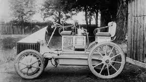
^ Ferdinand Porsche's first hybrid gasoline-electric vehicle. IC engine driving a generator to power electric hub motors. 1900 He also designed a similar, but much larger, hybrid drive system applicable to military "road trains" and railway cars.

-
When I posted what I posted, IT DID NOT WORK. Now, for whatever reason, it does. But thanks just the same.
-
All I get from that is "REPORT" and "SHARE" EDIT: Now it works. Very...whatever.
-
All I get from that is "REPORT" and "SHARE"
-
No edit function apparently...
-
Wrong. "Double hump" heads were the "fuel injection" heads on 327 and 350 engines, and first appeared in 1962. Other than casting numbers and the "humps" on the ends, they look just like other smallblock Chevy heads, especially in 1/25 scale.
-
I'll have to look up all the conversion factors, do the math, and check yours. It won't be any time soon. But suffice it to say for now...IC engines can be powered from rooftop-solar-powered hydrogen plants, adsorptive onboard storage makes for longer range at lower pressures, and the IC engine sound and feel doesn't need to be a thing of the past. Frankly, that's all I really care about at this point as far as the energy debate goes. This is from 2010, all that I could easily find that was closely related to Honda's late 1990's work... https://www.alternative-energy-news.info/honda-solar-hydrogen-station/ As of 2014, Honda also had a demo home with a solar array directly charging a DC-powered Fit, while running the rest of the house, with some power left over to dump on to the grid... https://newatlas.com/honda-smart-home-energy-producing/31380/
-
Hmmm. I just read through your posts in this thread and didn't see those numbers...but I can tell you for a fact that in the late 1990s Honda did a practical study using commercially available solar panels of a size compatible with the "average" suburban American residence, and they were able to produce enough hydrogen daily to fuel an efficient 4-passenger car for an "average" daily commute. NOTE: I don't have the study readily available as I'm in the process of moving my home, office, studio and shop 2000 miles west, but at the time my engineering consulting company was a dues-paying corporate member of the Natural Gas Vehicle Coalition. I was heavily involved, and stayed current on every facet of alt-fuels, alternative and "green" energy, the power distribution grid and infrastructure, adsorptive onboard storage of both compressed natural gas and hydrogen, etc. At the time I was appalled at the amount of hot air expended in the field versus the amount of constructive action...one of the reasons I withdrew my support from the group. Nothing much has changed. The rebleaters rebleat, politicians posture and pontificate, and the major corporations and the media get most everything wrong. Solar panels have become significantly more efficient since then, and optimization of IC engines to burn hydrogen has also made significant improvements in mileage/power output, which is fuel efficiency. So I'll go with Honda's results, thanks. And from my perspective and experience, I'd say that in a "typical city", a dense urban environment (like, ummm, NYC...where a lot of residents don't own vehicles anyway, and rely on public or hired transport), the amount of space for rooftop-hydrogen is a non-issue anyway. EDIT: But don't get me wrong. I'm not opposed to electric vehicles in principle. There's plenty of room for a rational mix of technologies to provide transportation. What I AM opposed to, however, is the ignorant insistence that electrics will solve everything and make the world all puppies and rainbows and unicorns.
-
Well, not really, and it depends. Most of the arguments for electric vehicles simply overlook a lot of basic physics, but numbers are apparently just too boring for the vast majority of proponents to bother with. The BEST gas-fired generating plants can achieve about a 50% conversion efficiency for the transformation of chemical energy (the energy contained in a combustible fuel) to-electrical energy. Oil and coal-fired plants are worse. Transmission losses at high voltage over long distances are about 2%. Lower voltage transmission losses over short distances are around 4%. So let's take a generous 3% transmission-loss-average and say we're at 47% efficiency by the time the electricity is at the plug where you recharge your batteries. That's before you charge your batteries and lose more energy in the process (you're converting the electricity at the plug back to chemical energy in a storage battery), and then there's more loss because the efficiency of transforming the electrical energy drawn from the battery into motion (mechanical) is hardly 100%. REMEMBER: EVERY TIME the FORM of energy changes, there are net losses. When all is said and done, and every erg is accounted for, the total net energy conversion from burning fossil fuel at a generating plant into making an electric car go down the road is going to be something on the order of 40%, or probably less. On the other hand, the BEST IC engines can currently get about 50% thermal efficiency, but the typical car on the road is only getting 25-30% useful work out of the fuel it burns. HOWEVER...direct-injection (available in cars since 2008) can raise this number to 35%. Add newer tech like engine stop-start, and make a concerted research effort to recover energy normally lost through cooling and exhaust system waste heat, and the potential for roadgoing IC engines to significantly better their electric counterparts in terms of energy efficiency should be obvious. NOTE: The huge MAN S80ME-C7 engine has achieved an overall energy conversion efficiency of 54.4%, which is the highest conversion of fuel into power by any internal-combustion engine to date (that I know of). Really want to save the planet? Make the fuel of choice hydrogen. It works just dandy in IC engines, and can now achieve thermal efficiencies as good as conventional diesels. Burning hydrogen in air produces nothing but water and relatively easily controlled oxides of nitrogen. It also works just dandy for fuel-cells for those who won't miss their engine noises, and in that case, the only "emissions" is water. Add in the fact that hydrogen can be easily made from filtered domestic wastewater by rooftop solar cell-powered electrolysis (Honda has already done most of the research long ago), and the optimum long-term zero-carbon transportation solution becomes apparent to anyone sufficiently versed in the REAL science to see the big picture. PS: In the interim, the carbon dioxide currently being pumped into the atmosphere by coal and natural-gas fired generating plants can be captured, fed to algae, and turned into bio-diesel and bio-jet fuel. This could have a significant impact towards achieving a carbon-neutral position. The tech exists. PPS: The much-touted "renewable" generating capacity, pure solar and wind, isn't there yet and is currently a pipe-dream. For the most part, "renewable" electricity is only available when the wind blows or the sun is shining, because storage of energy produced this way is difficult. One very expensive solar demo plant in Nevada using liquid sodium never did better than 50% of its design goals, couldn't pay back the costs associated with building it, and has been essentially abandoned.
-
Same place as all the bumf ?
-
ONLY $29.79 plus tax!!!
-
NASCAR 80's Coil position
Ace-Garageguy replied to SCRWDRVR's topic in Model Building Questions and Answers
Exactly. -
I tend to agree with ya. All the real military surplus seats I've seen (and I have a pair here) lack the "lightening" holes. It's not hard, however, to press nice round lipped holes in sheet aluminum with a set of matched dies that anyone with a lathe can make. Just for youse guys information, there were lotsa plywood surplus seats too...with no holes for the belts, 'cause when you're sitting on a 'chute, you sit high enough that the belts go over the seat rails. The wooden ones are much easier for an amateur to upholster, too. EDIT: The pix are hot-linked and may disappear shortly. If they do, I can post them from my own drives.