Ace-Garageguy
-
Posts
38,206 -
Joined
-
Last visited
Content Type
Profiles
Forums
Events
Gallery
Everything posted by Ace-Garageguy
-

Year-End Sprint for the Finish Line!
Ace-Garageguy replied to Snake45's topic in General Automotive Talk (Trucks and Cars)
Surely you jest. I spent an enjoyable evening cleaning off my bench in anticipation of getting some quality building time today and tomorrow. The universe had other plans. I'm now warming my hands over a space-heater after patching my old truck (blew the clutch slave cylinder this morning) enough so I can go out and get something to patch my furnace blower motor (it died in screaming agony shortly after midnight). Real life's a bidge sometimes. -
So, this AM shortly after the stroke of midnight, the fan motor bearing on my heater goes out. Of course it's the coldest day of the year so far (16F) with forecast colder the next few. Been working on it all morning to come up with with a patch until I can buy a motor later in the week (because of course, in this oh-so-much-better throw-away world the dweebs have created, I can't just buy the dammed bearing). And when I go out to my trusty old truck, she blows the clutch slave cylinder. Fixin' to hike up to O'Reillys to get one now. Hope this isn't the shape of things to come for 2018.
-
Hey happy new year?My Jeep battery is dead...
Ace-Garageguy replied to NYLIBUD's topic in The Off-Topic Lounge
I've had a lot of similar problems with Optima batteries over the last several years, which is why I no longer use them unless the client demands one...in which case I refuse to stand behind them, even if I install one. I've gone back to conventional lead-acid batteries for the cars I build where I specify all the components. -
Hey happy new year?My Jeep battery is dead...
Ace-Garageguy replied to NYLIBUD's topic in The Off-Topic Lounge
Cold weather kills batteries. Always good to have at least a small charger and a long extension cord handy in the winter. -
I'm not saying the assertion is completely wrong, as I just don't know. I really do NOT claim to know everything. But I DO know a pretty fair bit about structures, and until I see a photograph of one huge tube used as a race-car chassis, I'll have to refuse to believe it. What I DO know is that none of the cars cited above were based on big titanium tubes. I would hazard a guess that somebody not familiar with race car construction misinterpreted the phrase "titanium tube chassis" to mean one big tube, when it in fact means a conventional tubular chassis fabricated from small diameter titanium tubes. Interestingly though, a monocoque chassis with a roughly circular or ovoid cross-section CAN be loosely thought of as being a big tube. Aircraft fuselages and missiles are built that way too. BUT...in that case, the "tube" is built up of multiple alloy sheets bonded or riveted together, and it's necessary to include box-sections and ribs / bulkheads, as a pure tube has poor strength in bending if its walls are not adequately supported, either by the thickness of the material, or by box-section and rib / bulkhead elements. Below is a drawing of an early Lotus monocoque chassis built up from aluminum sheet, into a rough approximation of a "tube".
-
Yup. ALL "canopy" glues are basically the same stuff and behave similarly. Some are runnier, some tack up quicker, but they are all PVA and do just what you said. I tried the MKK, and it worked so well, I never bothered trying any others.
-
Lacquer has a hard surface, which is one reason it produces such a "deep" gloss when polished correctly. A hard surface makes it tougher to sand, but the results are worth it.
-
Thanks. Good to know. All of mine are Kidde.
-
I recommend Micro Krystal Klear. Bear in mind that none of these white PVA (polyvinyl-acetate) glues have much wet strength, and windows will usually need to be fixtured in position while drying
-
This image appears to be an early engineering / concept drawing of the 1965 Thompson FWD roadster. It would also appear that the radiator ducting is being designed here, to clear a reversed quick-change final drive assembly, driving the front wheels. The May 1965 Hot Rod Magazine article (page 44)shows the car nekkid, and it is definitely a conventional tubular space-frame, not some black-magic single titanium tube as has been alluded to. Still, I await independent corroboration. A too-hot nitro load for the last round of qualifying is cited in the Hot Rod Deluxe article, and could have conceivably contributed to the crank breaking, but at this point in history, I seriously doubt we'll ever really know. There has been so much discussion of the relative merits and failures of these cars, and so much written and talked about that has no basis in fact whatsoever, and quotes from M.T. himself describing how the deck was time and time again stacked against him (much of what he said is verifiably true), that arguing with nothing but memories to back up the positions of people who weren't there is pointless.
-
P.E. Saw Blade Recommendations?
Ace-Garageguy replied to Dodge Driver's topic in Model Building Questions and Answers
Yup. http://www.modelcargarage.com/store/pc/viewPrd.asp?idproduct=356 There's a learning curve, but if you have a functioning brain, it's not difficult to figure out what they will do without bending. And though they bend fairly easily, they also straighten out fairly easily as well. -
"Polishing" WILL NOT REMOVE ORANGE PEEL. It has to be sanded flat FIRST, and THEN polished. Sand up to 12,000 grit, wet, then polish. In the course of doing this, you naturally run the risk of sanding through the paint, and if you do, all you need to do is spray more paint, then re-sand and polish as necessary. Incidentally...Duplicolor straight rattlecan black should not need clear to develop a really fine gloss, but it may take 5 coats of paint to have enough to sand and polish if you get much peel.
-
Yes, it should ALWAYS be SOP to drain a tank prior to removing it...as well as keeping any sources of possible ignition FAR away. The manufacturers, in their non-hands-on, not-car-guys infinite wisdom, however, have nickel-and-dimed the drain plugs off of many fuel tanks, so you're kinda screwed when you go to drain some of them. Gasoline weighs about 6 1/2 pounds per gallon, so 10 gallons left in the tank is about 65 pounds. Handling that kind of weight overhead, sloshing around, with open lines, is a recipe for disaster. And a single drop of cold gasoline falling on a hot work-light bulb will crack the glass and start a fire instantly. I've seen fools with electric space-hearers in their bays too. Every toolbox needs it's OWN regularly maintained LARGE fire extinguisher, as well as extinguishers mounted on lift posts, and on the wall in FRONT of every work bay.
-
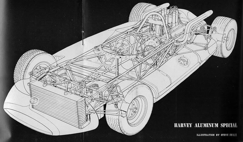
This is what I mean about all the wrong information floating around. The 1962 Harvey Aluminum cars ran Buicks (there were three), and looked relatively conventional for a mid-engined formula car, shown below. For the 1963 Harvey Aluminum "rollerskate" cars (blue, as shown in the post above and the cutaway drawing, all with tubular frames as shown, but only one of titanium) the Buick engines were replaced with smallblock Chevy engines. In '63, two of the earlier cars also ran with Chevy V8 engines, but under the "Harcraft" banner (a marketing division of Harvey Aluminum). The 1963 "rollerskate" cars were substantially modified and rebuilt as the Sears Allstate Specials for 1964, and had Ford 4-cam engines based on aluminum Fairlane bottom-ends. The red one is shown in the post above, next to the blue Harvey car it was built from (actually, the red Allstate #83 car was not on the titanium chassis...the #82 Allstate car was...). For 1965, there was no Harvey Aluminum-sponsored car listed either in the finishers OR the failed-to-qualify list. Micky Thompson's 1965 Indy entry, the M/T Challenger Wheel Special (black & white photo below) was an entirely new design again, front-engined (Chevrolet-derived), front-wheel-drive, and uncompetitive for several possible reasons, all of which have been argued endlessly. According to race accounts from the period, and not with 50 years of hindsight and speculation clouding things, the crankshaft in the last qualifying engine broke as the car was almost up to a respectable speed. As both alcohol AND gasoline fuels were run in the '65 race, it's not inconceivable that a fuel mixup might have occurred, but I feel it's unlikely. The engine in Thompson's car had suffered from development problems, the program was behind schedule, and they just ran out of time before getting it right. Honestly, I do NOT know much about the chassis of this design. It's entirely possible Harvey Aluminum was involved with the project, as they were also involved with the casting of Thompson's other products and special parts, but without a definitive reference source, I'll keep silent on what I believe the chassis to be. Thompson skipped 1966 at Indy, but was heavily involved in 1967 with another radical design incorporating 3-valve-per-chamber heads on a Chevy bottom end. The Wynn's-sponsored front-engined roadster also failed to qualify, as did Thompson's '68 entry.
-
Micro Balloons questions.
Ace-Garageguy replied to HotRodaSaurus's topic in Model Building Questions and Answers
Most likely 'cause there's nobody over there who knows. Microballoon is used frequently in flying RC model planes, but not much in other hobby models. My extensive experience with the stuff comes from real aircraft applications, and years of experimenting on static models. -
The tube-frame cars as shown above were heavily modified and rebodied to become the 3 Sears Allstate Specials for 1964, running the Ford DOHC V8.
-
Amnesty build-Monogram 1934 Ford Cabriolet
Ace-Garageguy replied to Eric Macleod's topic in WIP: Model Cars
Dennis is correct. Non-finned aluminum heads were factory stock. -
Autoquiz 354 - Finished
Ace-Garageguy replied to carsntrucks4you's topic in Real or Model? / Auto ID Quiz
One of the few sports cars you can take out and flog in the snow. -
Enamel is usually the problem-child, though it's definitely always a good idea to experiment on one before you commit to painting all your tires.
-
With a little effort, the Comet-and-toothbrush gets down in the treads just fine. I've been doing it for decades. Bet effort IS required, and we all know how unpopular that is.
-
The June 1963 Hot Rod Magazine has a full writeup on the "rollerskate" car (the June '63 Road & Track has a comparison of Thompson's rollerskate and the Lotus 29 as well). August '62 Hot Rod has details of the more conventional looking Thompson/Harvey first-generation mid-engined car. There were developments over several years, and it can all get a little confusing...and there's no shortage of just flat wrong information floating around too...as usual. The elliptical cross section was only the skin. The chassis was a relatively conventional tubular spaceframe, built of .050"-wall titanium tube.

-
-
Gasser Engine Mounting Angle
Ace-Garageguy replied to afx's topic in Model Building Questions and Answers
Having the shafts slightly offset, as referenced above, only serves to keep the joints "working", and lubricated. Obviously, as the suspension moves around (when the car negotiates a bump, for example), the offset angles will become more severe during the up and down movement of the vehicle. If the bearings in the joints have run dry because the shaft is too straight most of the time, they may not be able to cope effectively with the increased loads caused by greater offset angles, and early joint failure may result. Three things are usually responsible for driveshaft vibration. 1) By far the most common in hot-rods or engine / trans swaps is a failure to match the pinion angle to the angle of the crank / trans centerline. That's one reason why the articles and illustrations you found make such a big deal about it. As noted in my first response, the angular velocities of shaft elements are different on either side of each joint at various degrees of shaft rotation. A properly set-up shaft, with the angles of the pinion and crank centerlines matched closely (with the vehicle at its normal going-down-the-road ride height) will cancel out these variations and both ends of the shaft will have the same instantaneous angular velocities at any given time. Mismatched pinion / crank centerline angles will have both ends of the shaft fighting each other as their angular velocities change at slightly different rates. Depending on the design of the rear suspension and the compliance of engine and drivetrain mounts, this may be felt as a vibration at certain road-speeds or loads. It will certainly hasten UJ failure. NOTE: Not all rear suspension designs are equal when it comes to maintaining pinion angle under all conditions. Consider a live rear axle on coil springs, controlled by trailing arms. In this design, the rear axle will move in a slight arc as it moves through its bump / rebound travel, and will rotate around its centerline. The pinion angle will change during this movement. 2) Another leading cause of driveline vibration in non-OEM installations is having the universal joints slightly "out of phase". This happens when an inexperienced or sloppy driveshaft builder fails to align the crosses of the UJs EXACTLY, for instance, where a shaft has been shortened or lengthened, or a yoke on one end of the shaft has been changed to accommodate a different trans or rear end. This will usually manifest itself in a moderate to severe vibration at all road-speeds. Competent driveshaft shops almost always get this right. Guys who shorten or otherwise modify their own shafts rarely do. NOTE: It IS possible to do a fine job of modifying a shaft in the garage or home shop, even without a lathe. But it takes an amount of CARE and THOUGHT that is usually lacking among amateurs, and a lot of "professionals". 3) The third cause of driveshaft vibration is simply out-of-balance. Driveshafts need to be balanced, just like any other rapidly rotating component, and they usually have small weights welded to them to accomplish this. When a shaft is modified, it needs to be re-balanced by a competent shop. An out-of-balance shaft will often be felt as a cyclic vibration at some vehicle speeds, not others. Getting hot-rods and customs to behave like OEM vehicles can be time consuming and frustrating, particularly when the original builder(s) failed to take things like these seriously. NOTE: On a pure drag-racing car as shown in the opening photo, having the driveshaft running almost or dead straight is really OK. The car isn't going to be run for miles and miles on end with the UJs not "working", so with an occasional shot of grease, the joints will be just fine...but the crank / trans centerline angle and the pinion-shaft centerline angle still need to match exactly. -
Gasser Engine Mounting Angle
Ace-Garageguy replied to afx's topic in Model Building Questions and Answers
This is one of those instances where insufficient knowledge and experience can lead to incorrect assumptions and interpretations. The diagram you found is CORRECT the way it labels "wrong" and "right". If you look closely, you'll read that the centerlines of the pinion shaft and the crank centerline are parallel, which I noted is necessary in my comment above in NOTE 2. You will also notice that they are not excessively offset, which I referred to in this part of my response: "With universal joints operating at higher angles etc." The car and engine in your photo in the opening post are both excessively jacked up, and to approach the relatively minor offsets of the shaft elements in your last illustration, the engine needs to be angled as shown. I assure you, if you were to draw this all out to scale, you can get the relatively minor shaft offsets necessary for correct universal joint operation with the engine at that apparent angle. HOWEVER...not ALL car builders appreciate all the subtleties of pinion-angle and driveshaft setup, and some pretty spectacular results have been known to occur, like when the front UJ snaps and the car pole-vaults on the driveshaft. -