
Chariots of Fire
-
Posts
2,797 -
Joined
-
Last visited
.thumb.png.e64ca4fead948adbdf6a111229b6cf2f.png)


Recent Profile Visitors


Chariots of Fire's Achievements
MCM Ohana (6/6)
-
Agree with Peteski. When drilling out you can also use a chrome pen to color the back side of the lens after it is in place. The one thing NOT to do, however, is get glue on the lens, either inside or outside because it will ruin the effect. If you can make a backing first, so much the better. I avoid the glue issue by using two-part epoxy sparingly around the edges..
-

R Model Mack in 1/32 scale
Chariots of Fire replied to Chariots of Fire's topic in Model Trucks: Big Rigs and Heavy Equipment
If you have any issues with the casting be sure to contact me. The hood may need a small amount of tweaking and the windshield area is unique. -
R Model Mack in 1/32 scale
Chariots of Fire replied to Chariots of Fire's topic in Model Trucks: Big Rigs and Heavy Equipment
Hey, Bob! Well, a little of both. I found a Mack dump image on line that was a great side view. I saved it, brought it over into the graphics program and resized it to fit the model. Then used the image to make up the sides. Everything else went from there. -
Maxim F model
Chariots of Fire replied to Firebuilder's topic in WIP: Model Trucks: Big Rigs and Heavy Equipment
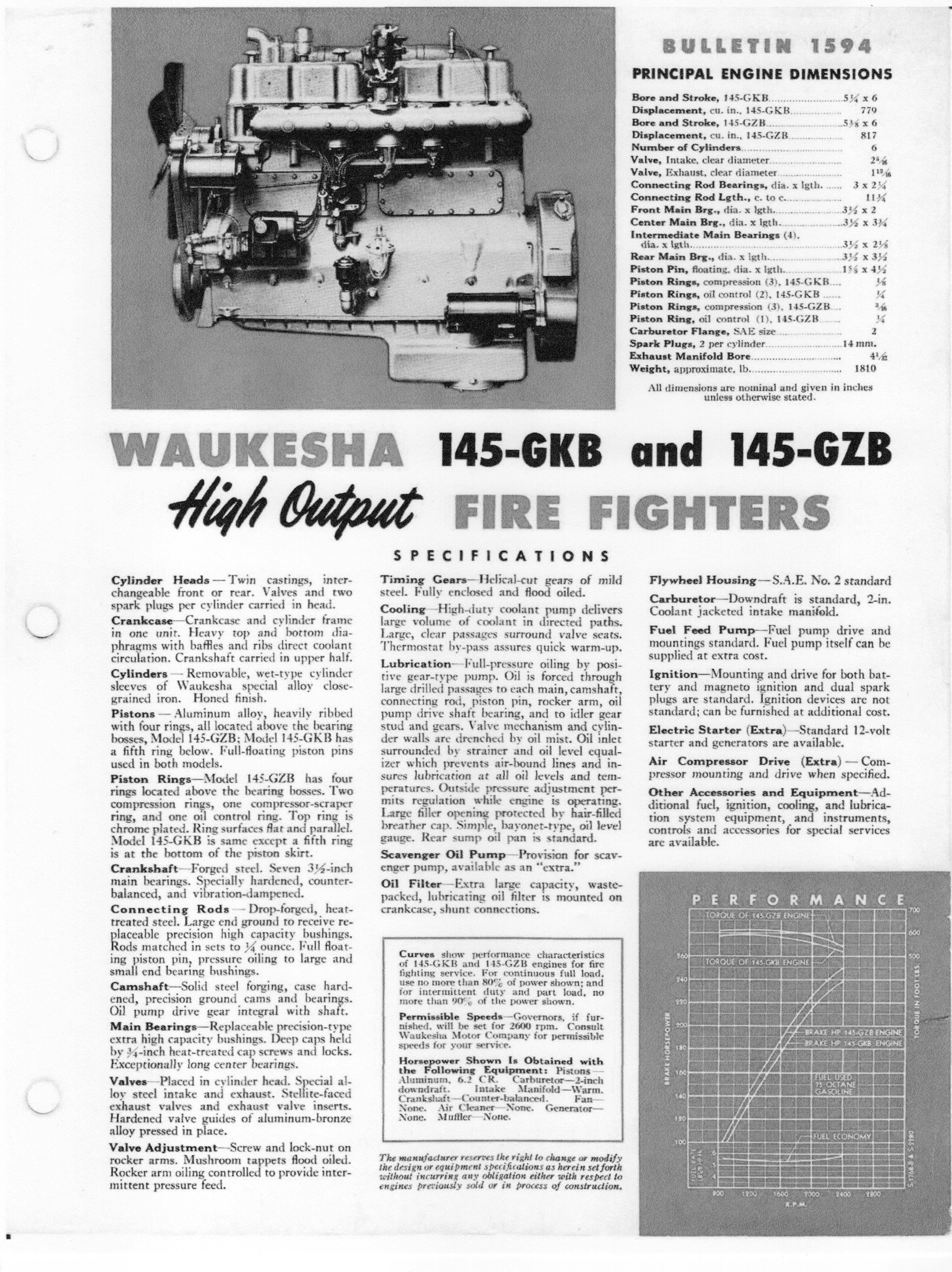
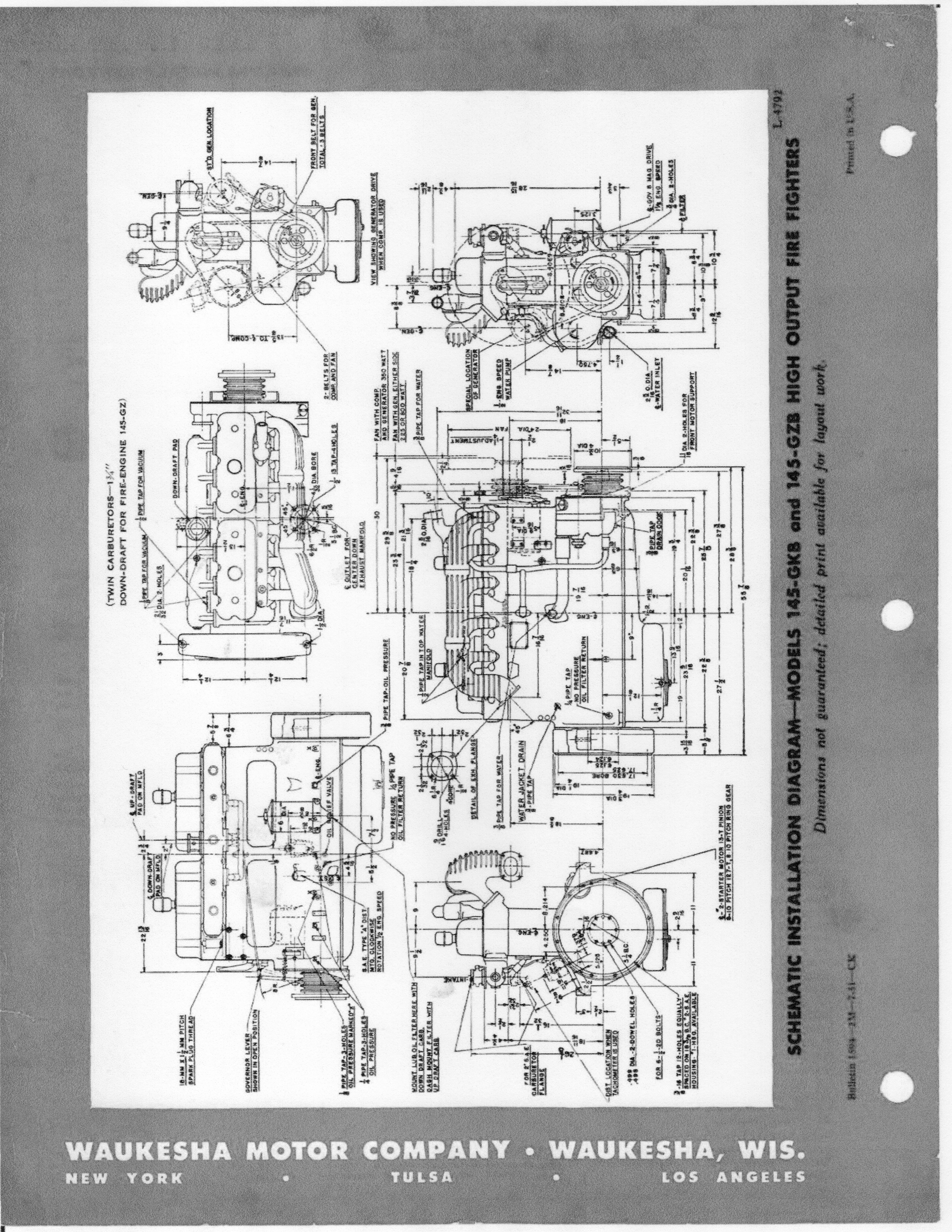
Just found this Waukesha "fire fighter" brochure. Might be helpful.
-
Maxim F model
Chariots of Fire replied to Firebuilder's topic in WIP: Model Trucks: Big Rigs and Heavy Equipment
Waukesha was quite common along with Hall Scott and Hercules. -
Maxim F model
Chariots of Fire replied to Firebuilder's topic in WIP: Model Trucks: Big Rigs and Heavy Equipment
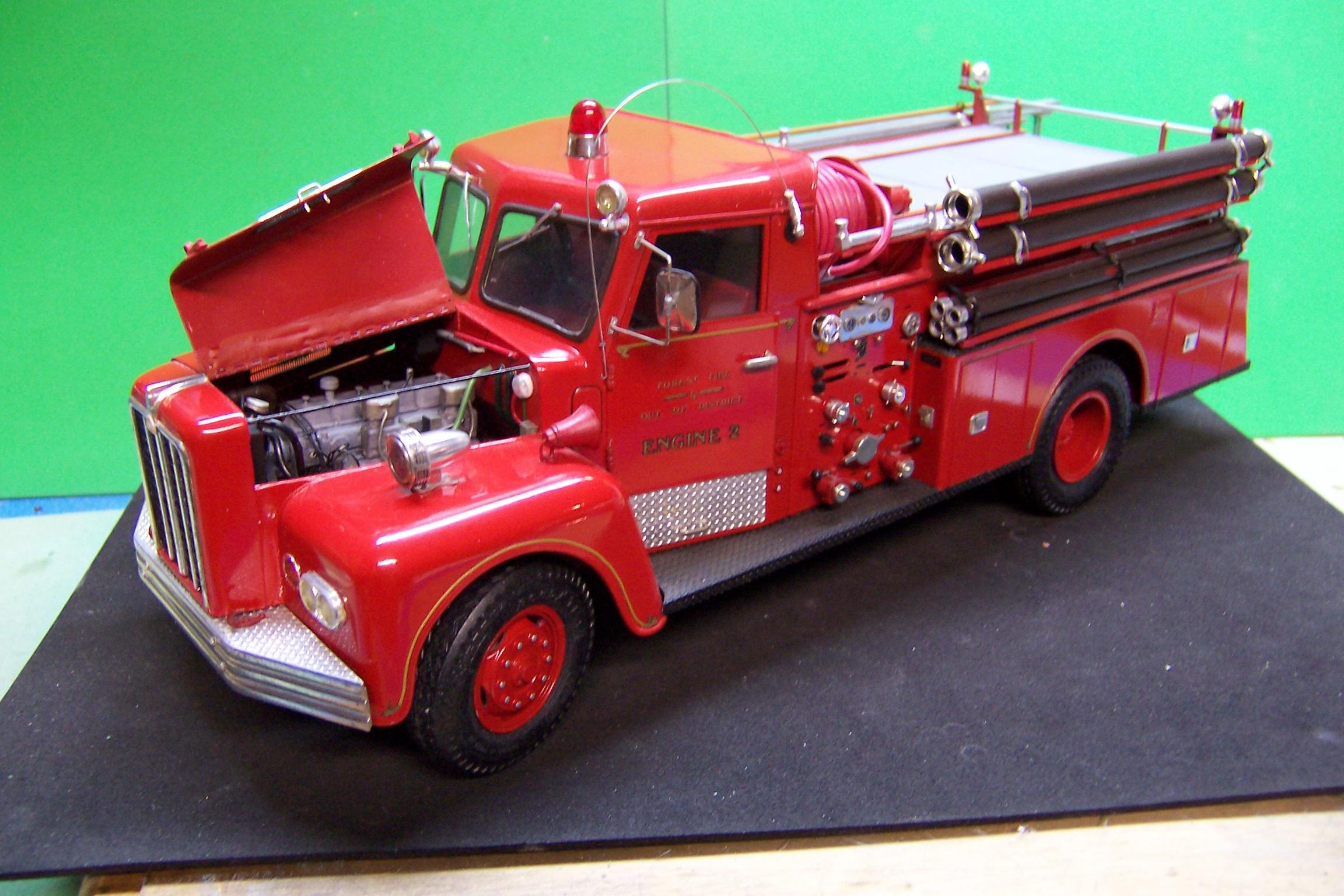
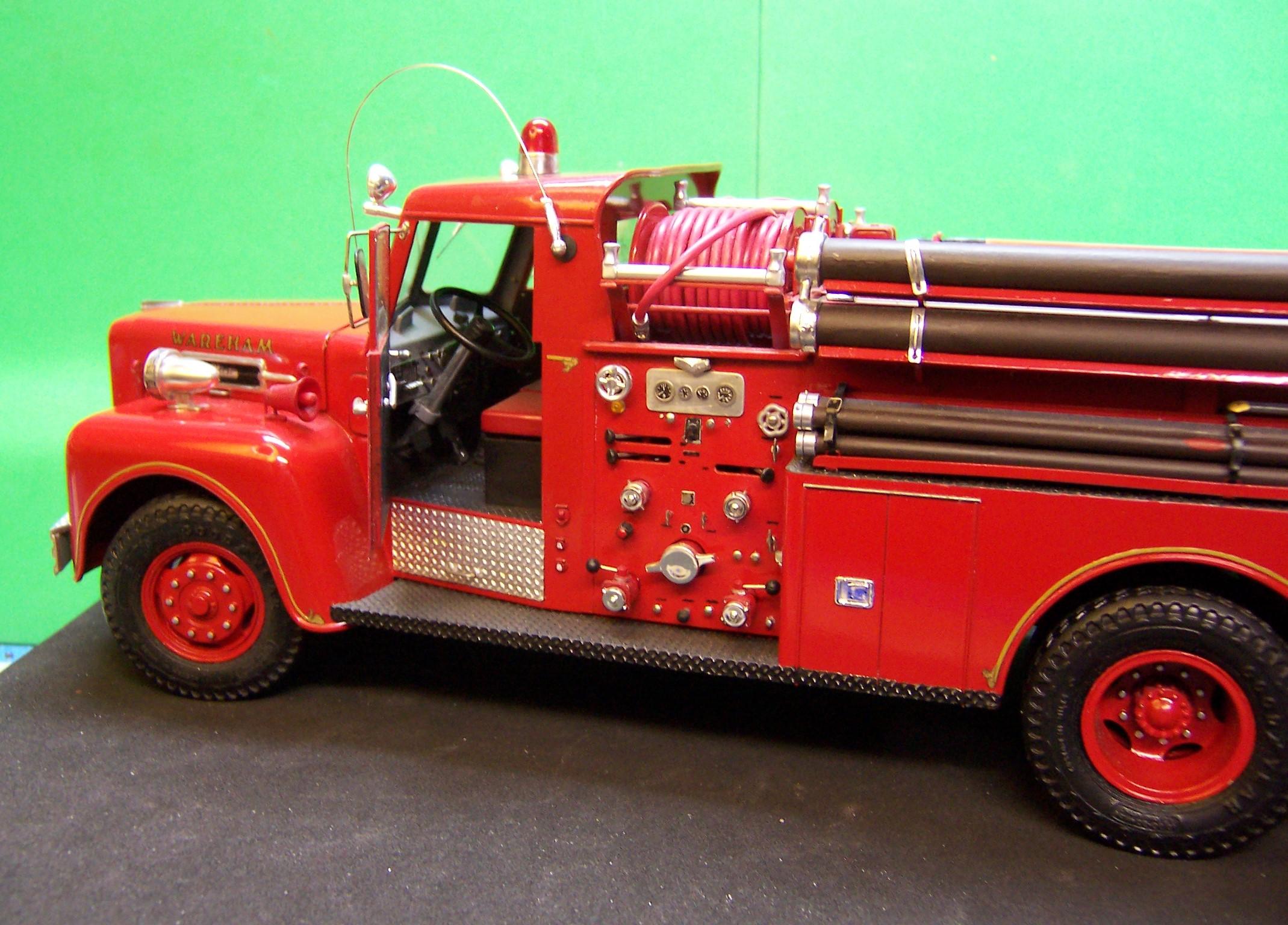
Go on line and find Waukesha engine images that you can use to detail the Mack. The Waukesha gas engine had two valve covers and had dual ignition as I remember. I made up one for the '61 Maxim S model. Here are a couple of looks at it.
-
Most vent windows back in the day were surrounded by a black rubber gasket. So outline the edge of the window with a black sharpie and just use the chrome to paint the face of the post between the vent and the main window glass. That should cut down on the amount of chrome and make the window look more to scale.
-
Ford LS Rescue truck
Chariots of Fire replied to gotnitro?'s topic in WIP: Model Trucks: Big Rigs and Heavy Equipment
Can I make a suggestion? Drop the cab down some so that the bottom of it is about even with the top of the frame. That will fill in the gap between the fender opening and the top of the front tires and will make the steps into it closer to the bottom of the body you are building. It's looking good from here. Check out some rescue images and I think you will see what I mean. -
'F O R D ' hood lettering ?
Chariots of Fire replied to jdcar32's topic in Model Building Questions and Answers
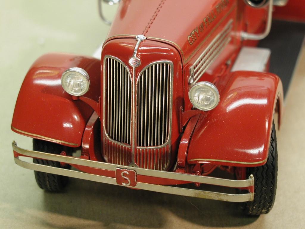
I've used the foil over primer trick for years. Works for almost everything. The bright work on the front of this 1937 Seagrave is a combination of aluminum wire for the interior of the grill but BMF was used around the outside and for the extension of the grill at the bottom. I painted the red over the BMF at the bottom and then gently removed the paint with a Q-tip and a small amount of thinner.Did the same on the Mack script on the 1/32 scale R model dump that I just finished. Nice thing about doing script and badges is that you don't have to cut away every little nook or cranny. Scribe the BMF with a new X-axto blade flush with the outside of the script and burnish it down good. The paint will hide the edge of the foil nicely.
-
R Model Mack in 1/32 scale
Chariots of Fire replied to Chariots of Fire's topic in Model Trucks: Big Rigs and Heavy Equipment
Yes, it is, Lee. Dave should be able to supply you with the cab and all that goes with it. Here's another one I did using the same cab.
-
R Model Mack in 1/32 scale
Chariots of Fire replied to Chariots of Fire's topic in Model Trucks: Big Rigs and Heavy Equipment
IH fan I see. Here's another dump for you.
-
R Model Mack in 1/32 scale
Chariots of Fire replied to Chariots of Fire's topic in Model Trucks: Big Rigs and Heavy Equipment
Could have cast them, Jim but I have so many parts boxes of these snap kits I just grabbed some. 3D printed is not something I even thought of.🙂 -
R Model Mack in 1/32 scale
Chariots of Fire replied to Chariots of Fire's topic in Model Trucks: Big Rigs and Heavy Equipment
The Monogram Snap kit of the CF pumper has them. It takes two kits to get the 4 needed for the tandem rear axles.
-
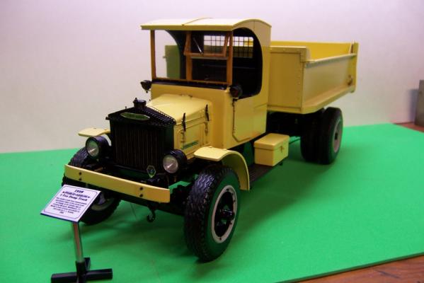
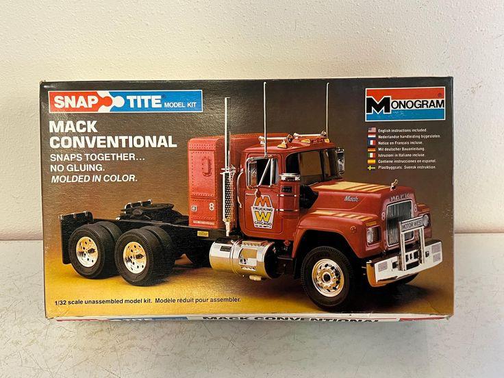
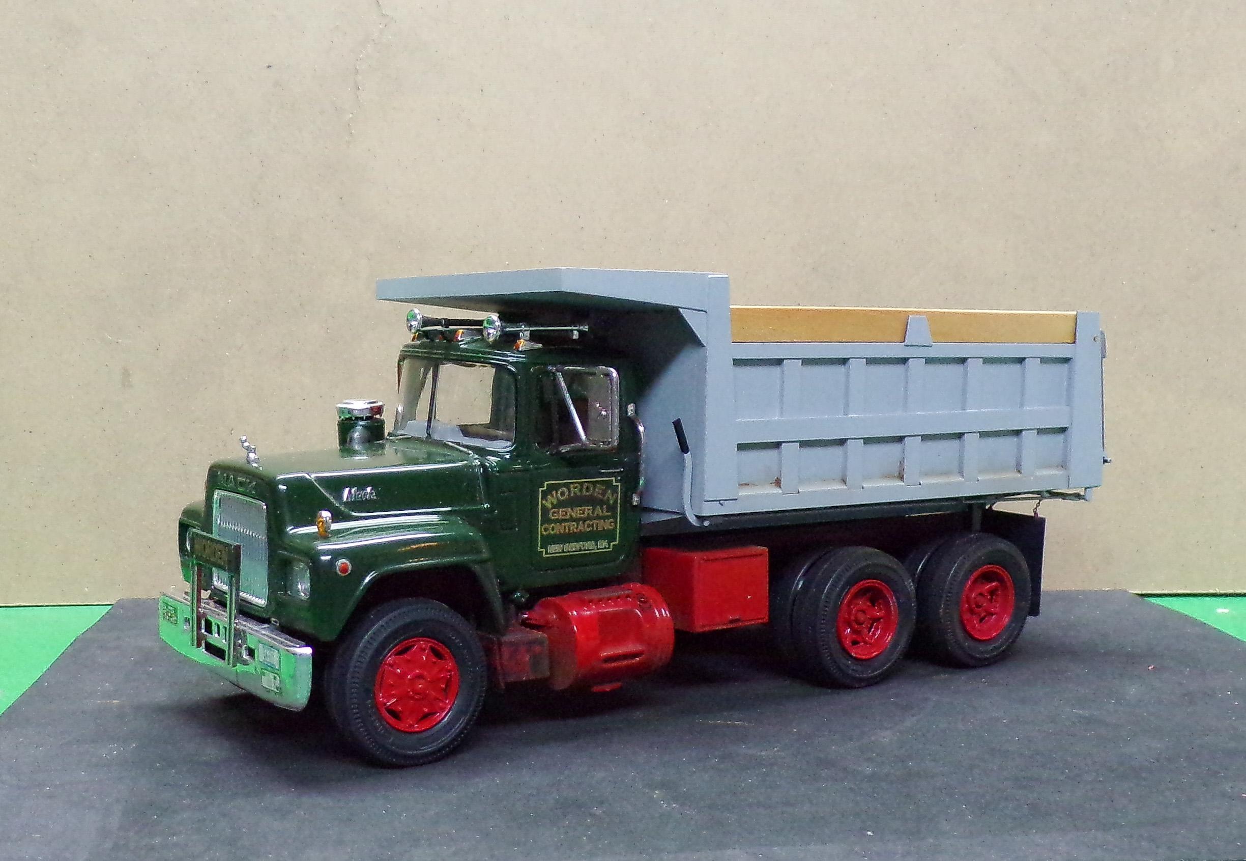
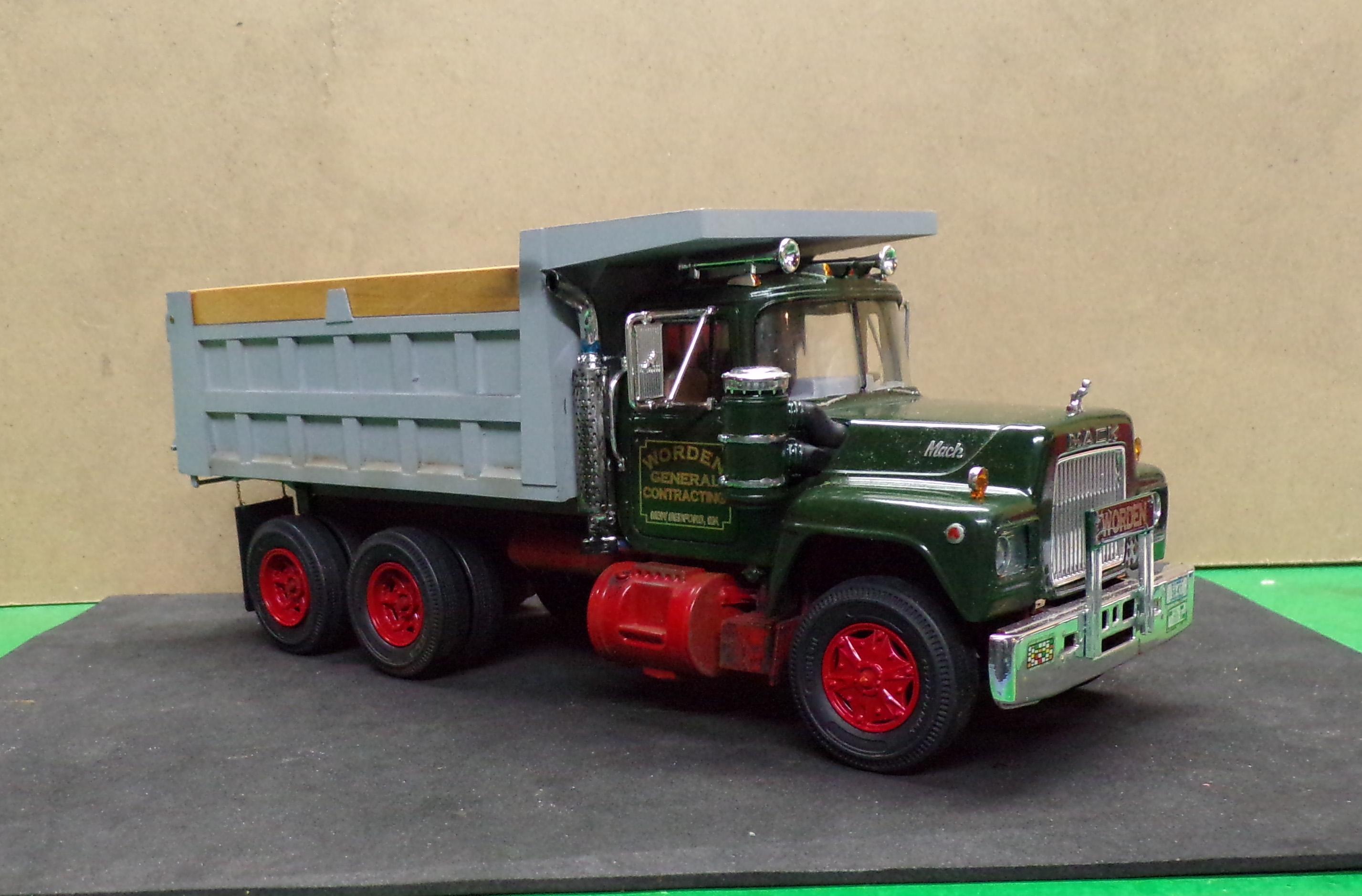
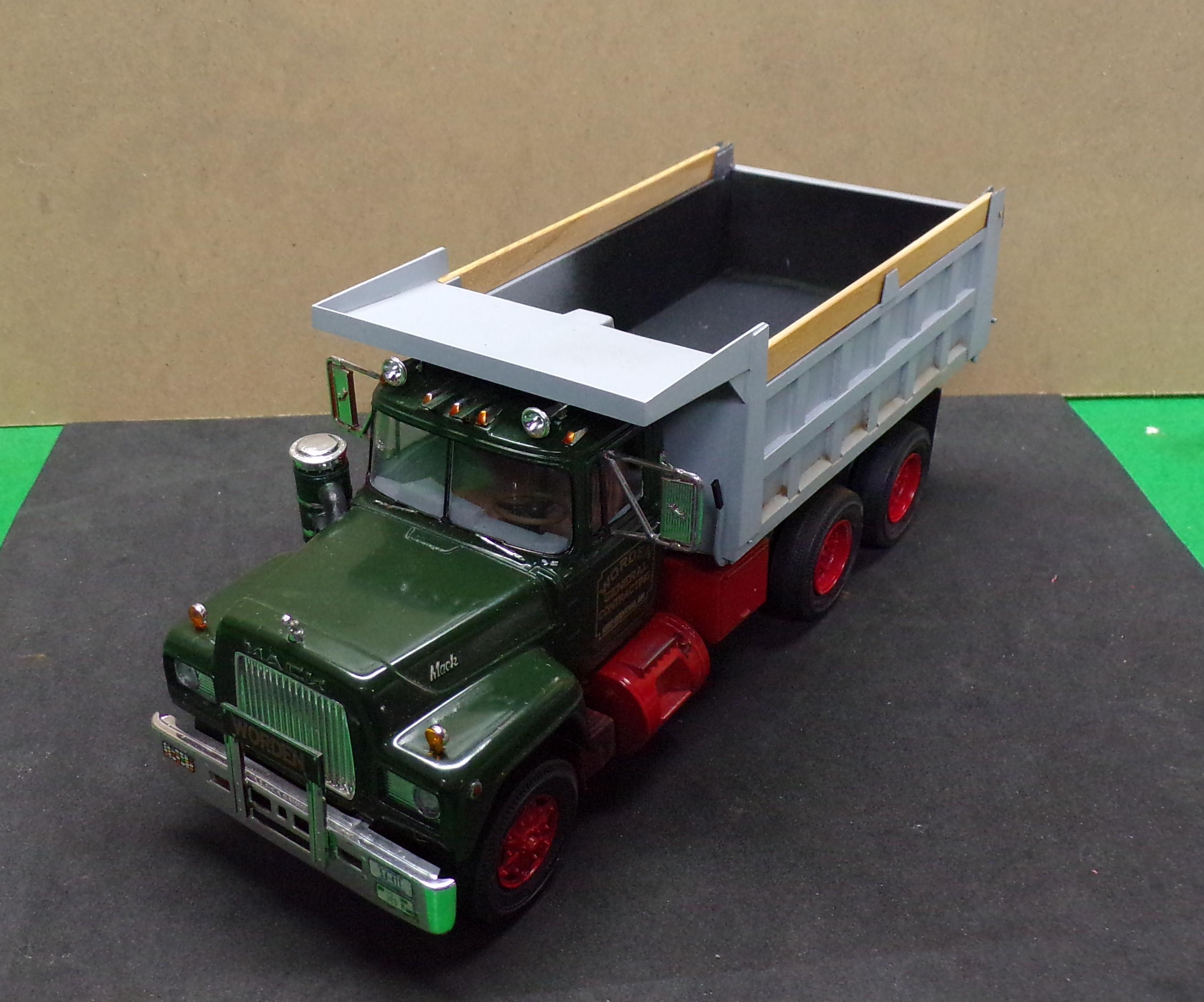
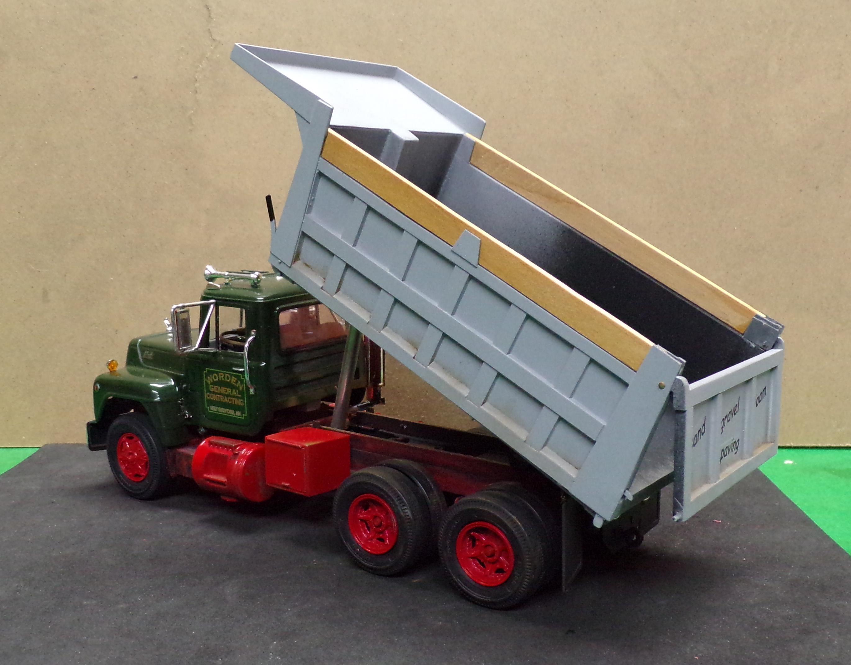
I should have taken photos of what I started with but the box art will have to do. This tractor was built up but not in good condition so I took all the pieces down, cleaned them except for the frame, which was left dirty and built a dump version. The sleeper was removed, a new back wall for the cab built, fuel tanks cut down, tool box and air tank added, new mud flaps and a new body made of Evergreen sheet and strip stock was installed. The paint on the cab is Tamiya British green. Red is Duplicolor and the body is Duplicolor primer gray. The decals were printed on ALPS. Zoet Chrome pens cleaned up some of the smaller pieces and Fusion Film was used on the modified exhaust stack. The hoist is made of aluminum tubing and the tail gate opens with the handle next to the cab. A fun restoration for a change.☺️
- 26 replies
-
- 12
-

-
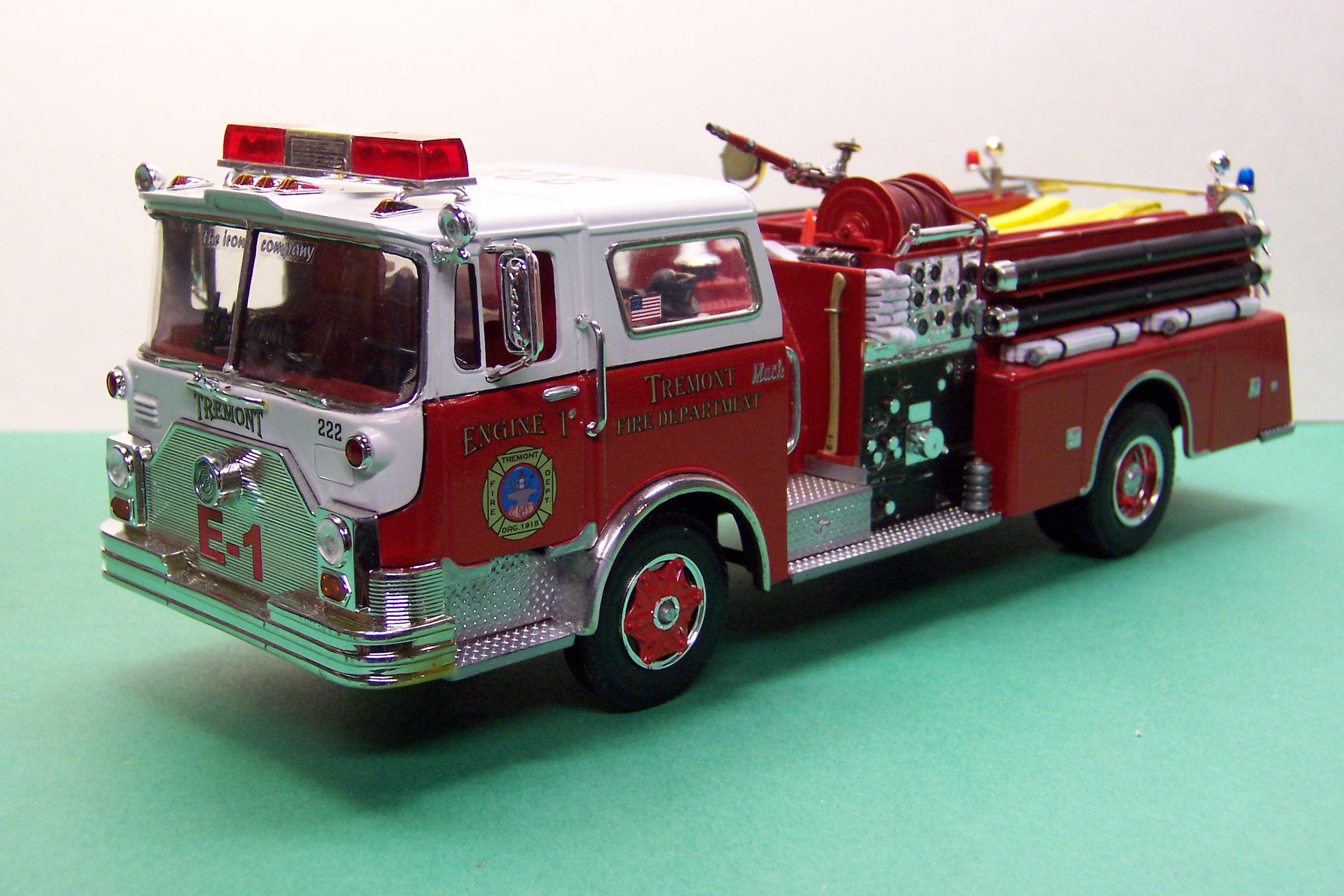
I had a friend give me a piece of reflective vinyl once that they used on real municipal vehicles. I cut it into the strips I want and lay it on. Super sticky backing so it has to go on correctly the first time but they do look nice. Here's an example. The yellow stripes are 3M tape. The white ones are the reflective vinyl.


.JPG.3b0ab02b97c1d3790a91eab93c5022b0.JPG)