Anglia105E
-
Posts
3,487 -
Joined
-
Last visited
Content Type
Profiles
Forums
Events
Gallery
Everything posted by Anglia105E
-
Rolls-Royce No Chemicals, No Paint, No Harmful Glues
Anglia105E replied to Anglia105E's topic in WIP: Model Cars
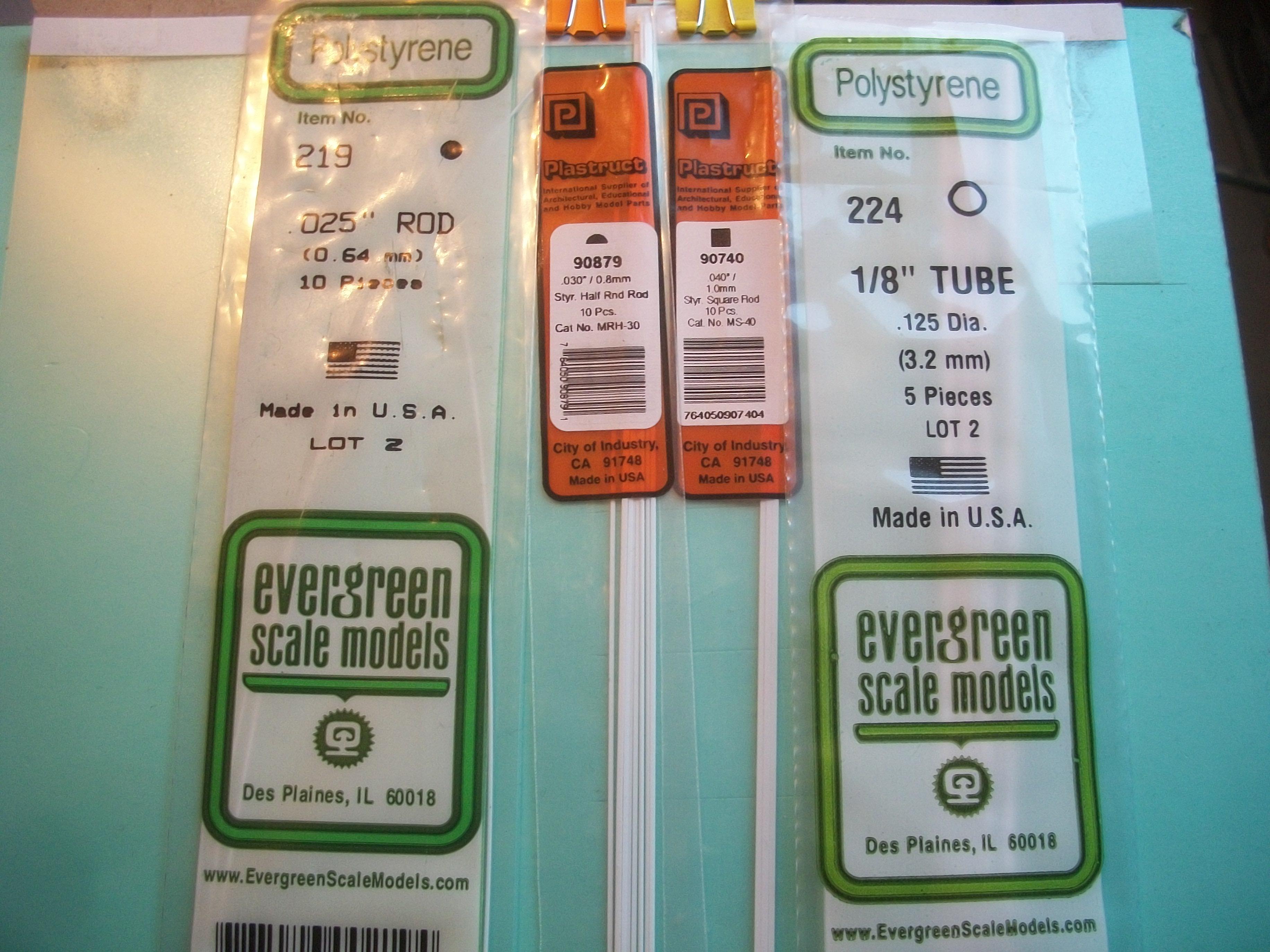
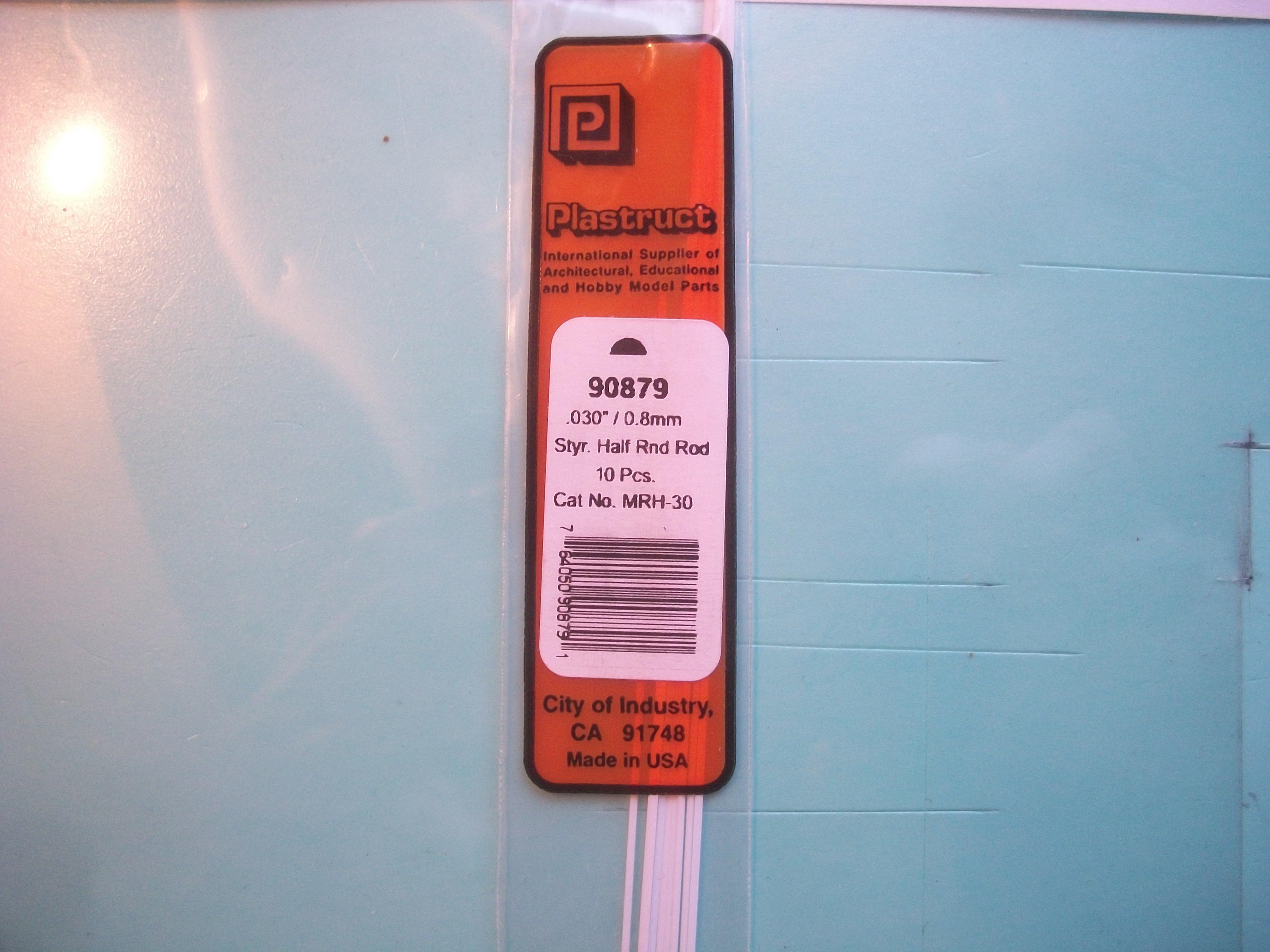
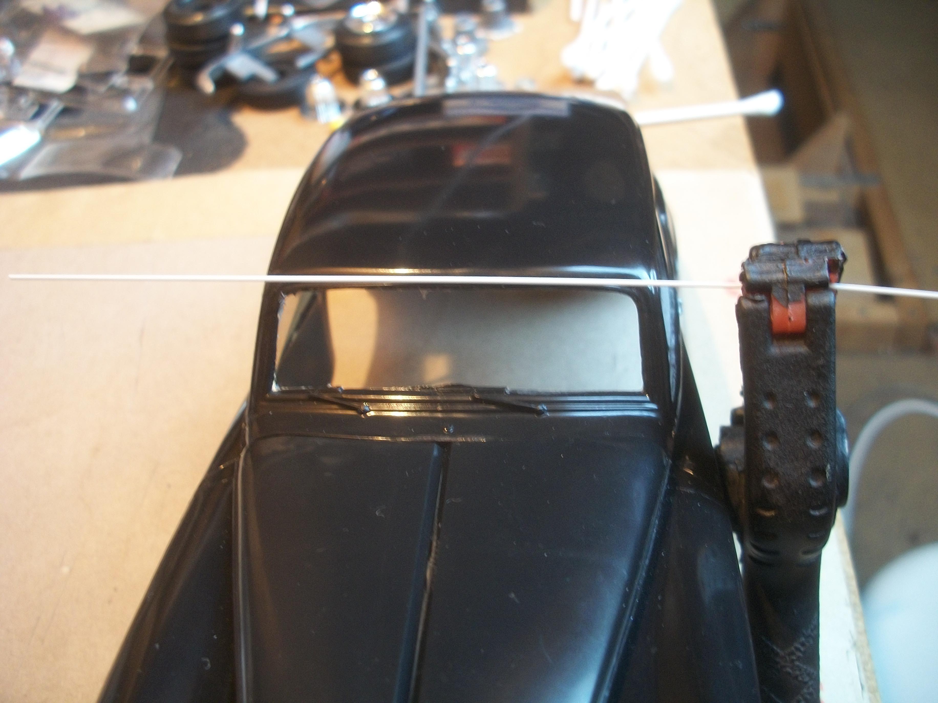
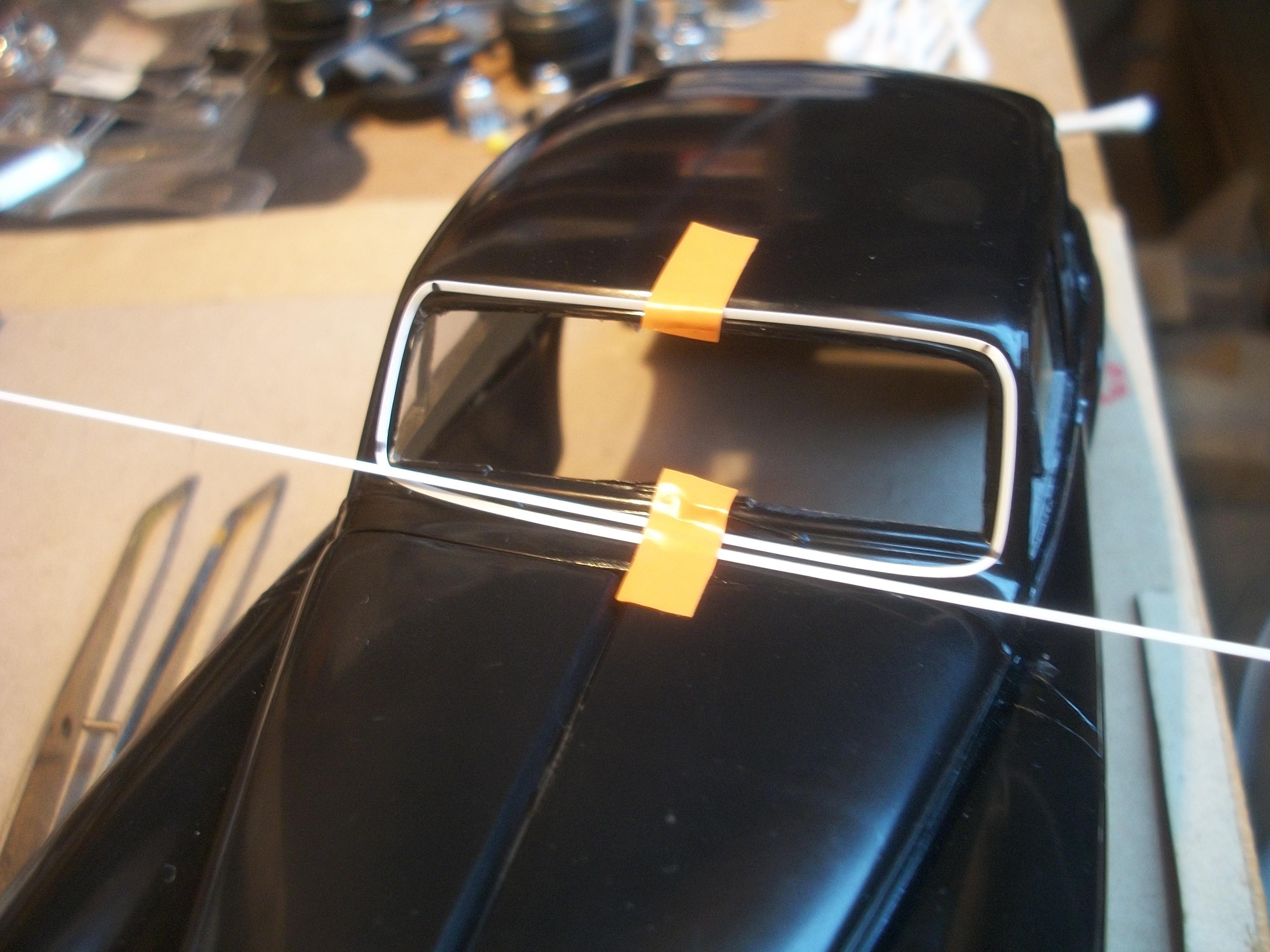
I brought to the table a previous Silver Cloud build, and this one has quite a good windshield in place. The method used to build this model was to cut a length of styrene rod to go around the opening for the screen on the outside. For this current build, I have selected a length of Plastruct .030" Half Round styrene which is 0.8 millimeter . . The idea is to glue the styrene moulding in position, with the clear screen already glued in place, probably using PVA glue. Previously I would have used Revell Contacta Professional cement, but this has a very strong smell, so I must avoid this product. It will be necessary to apply the silver Sharpie to the Plastruct moulding before carefully positioning the part with tweezers, so as not to handle the moulding. David
-
Rolls-Royce No Chemicals, No Paint, No Harmful Glues
Anglia105E replied to Anglia105E's topic in WIP: Model Cars
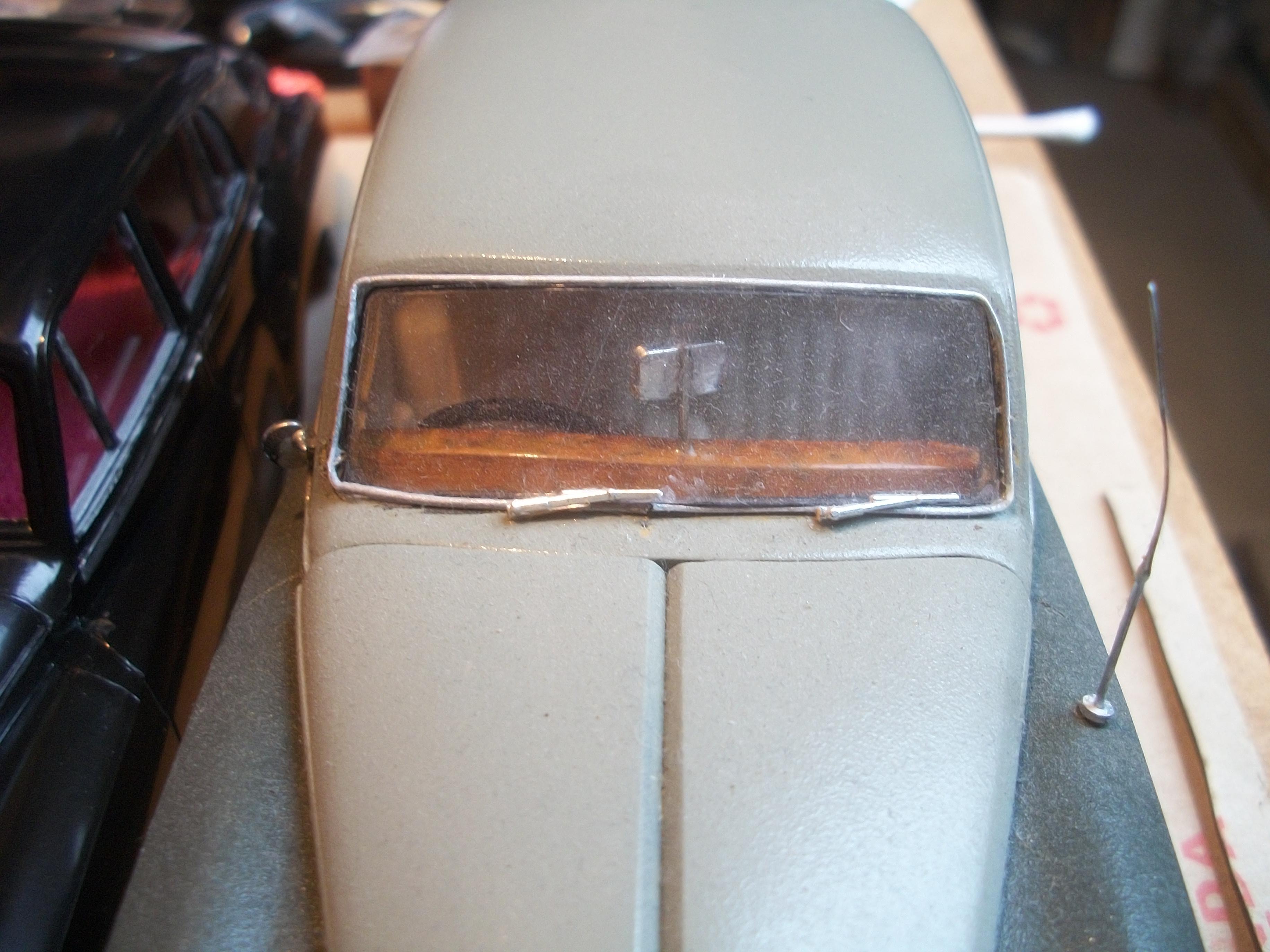
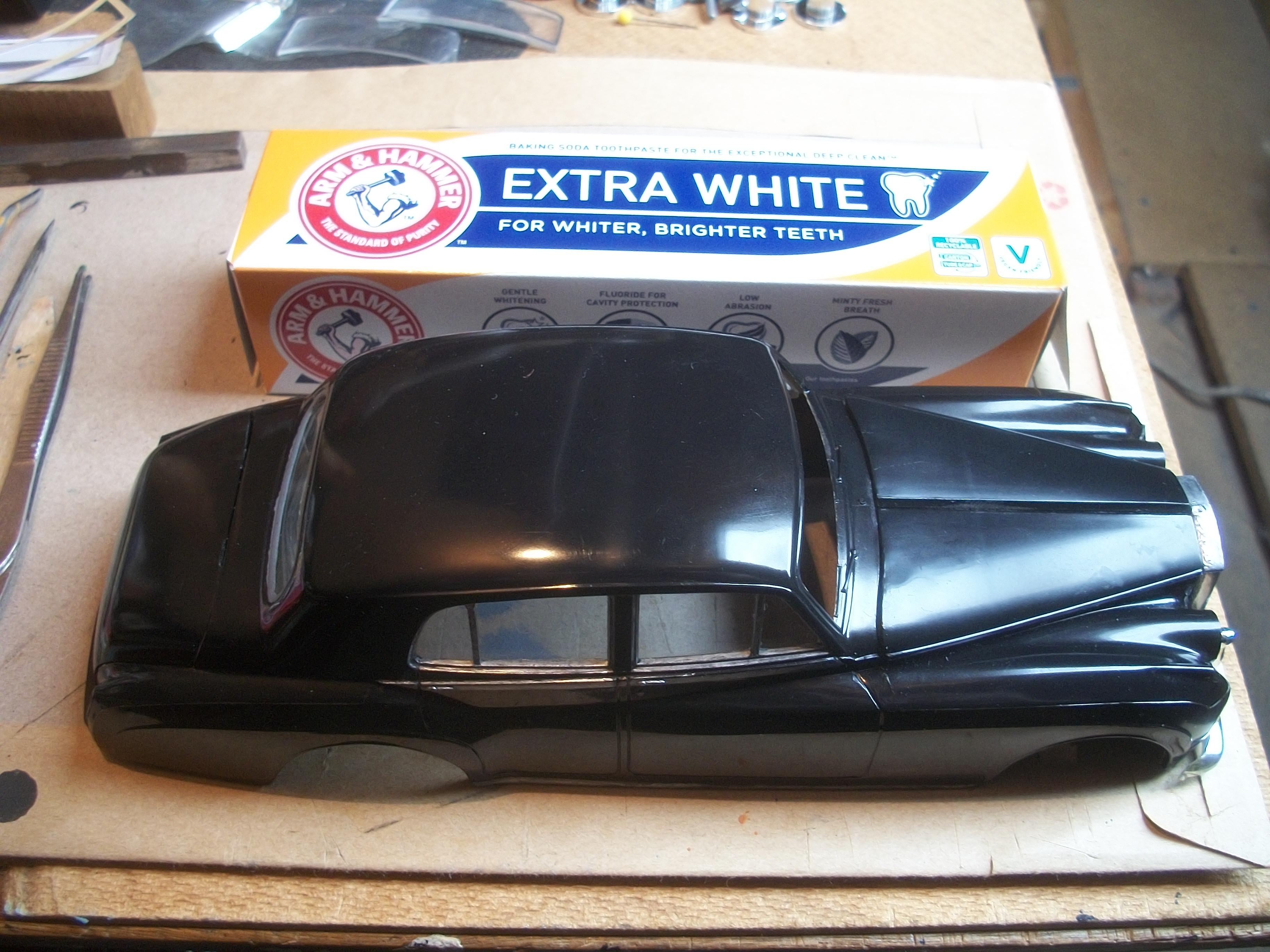
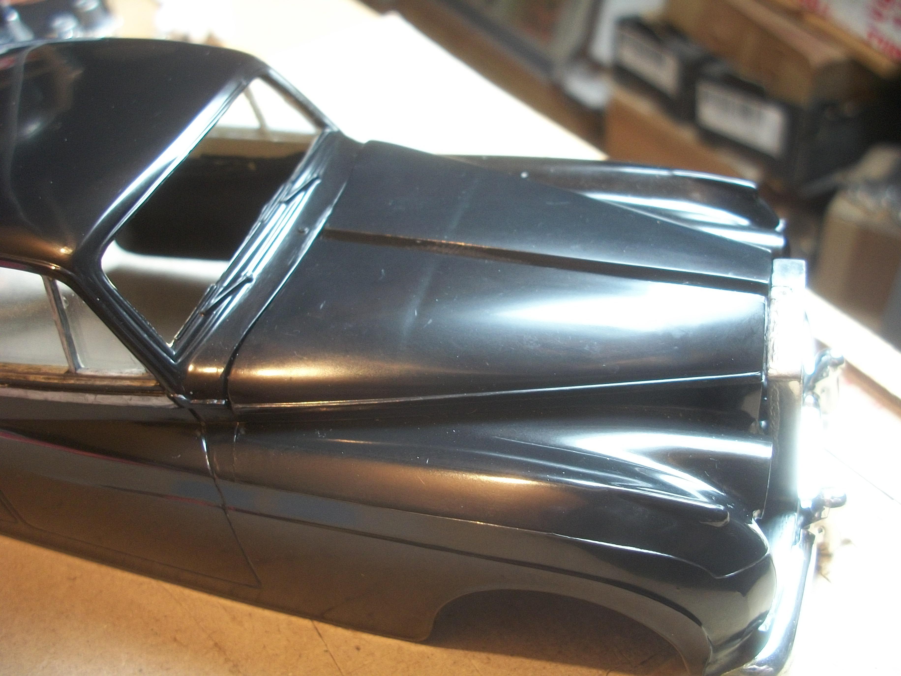
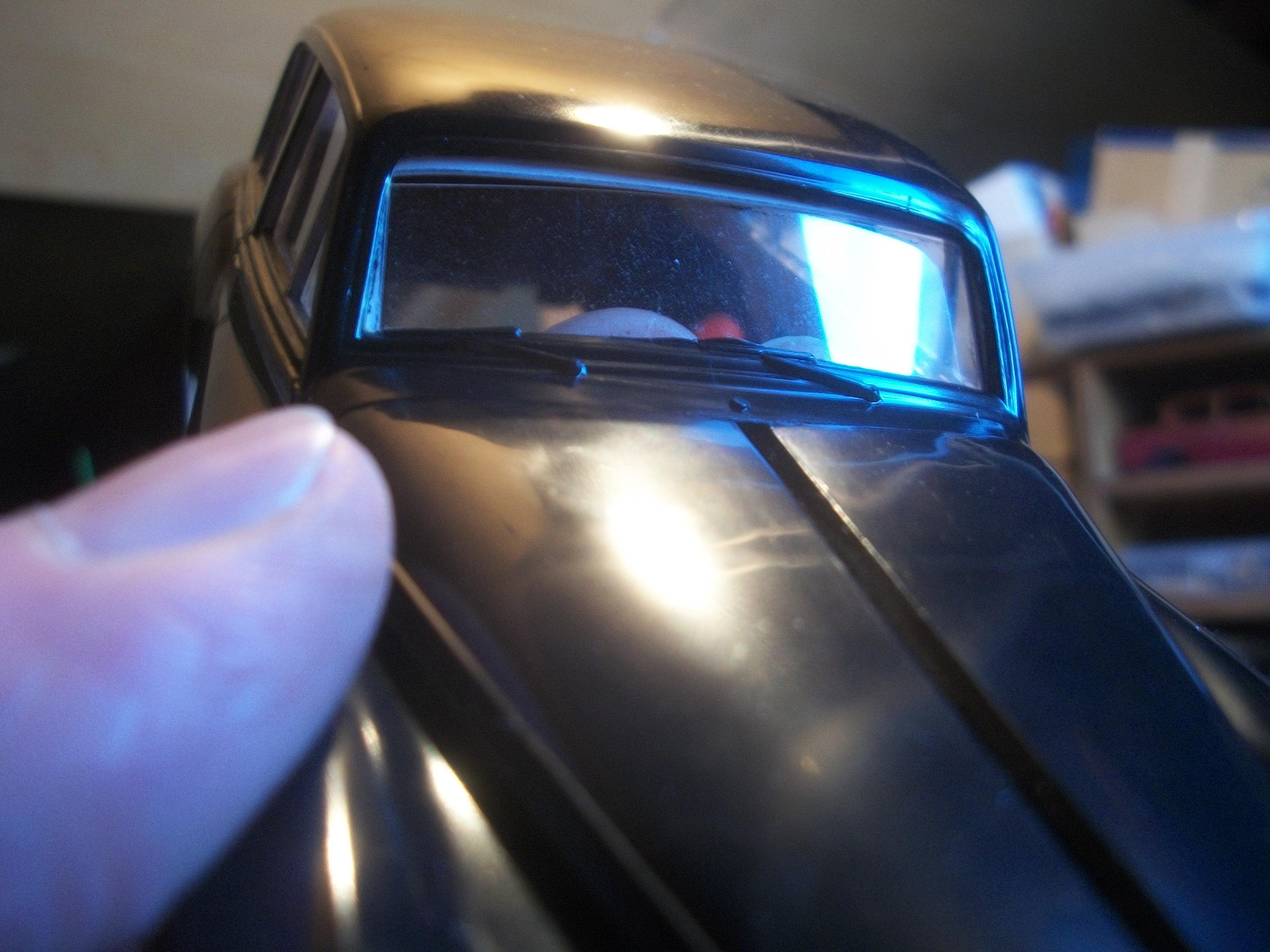
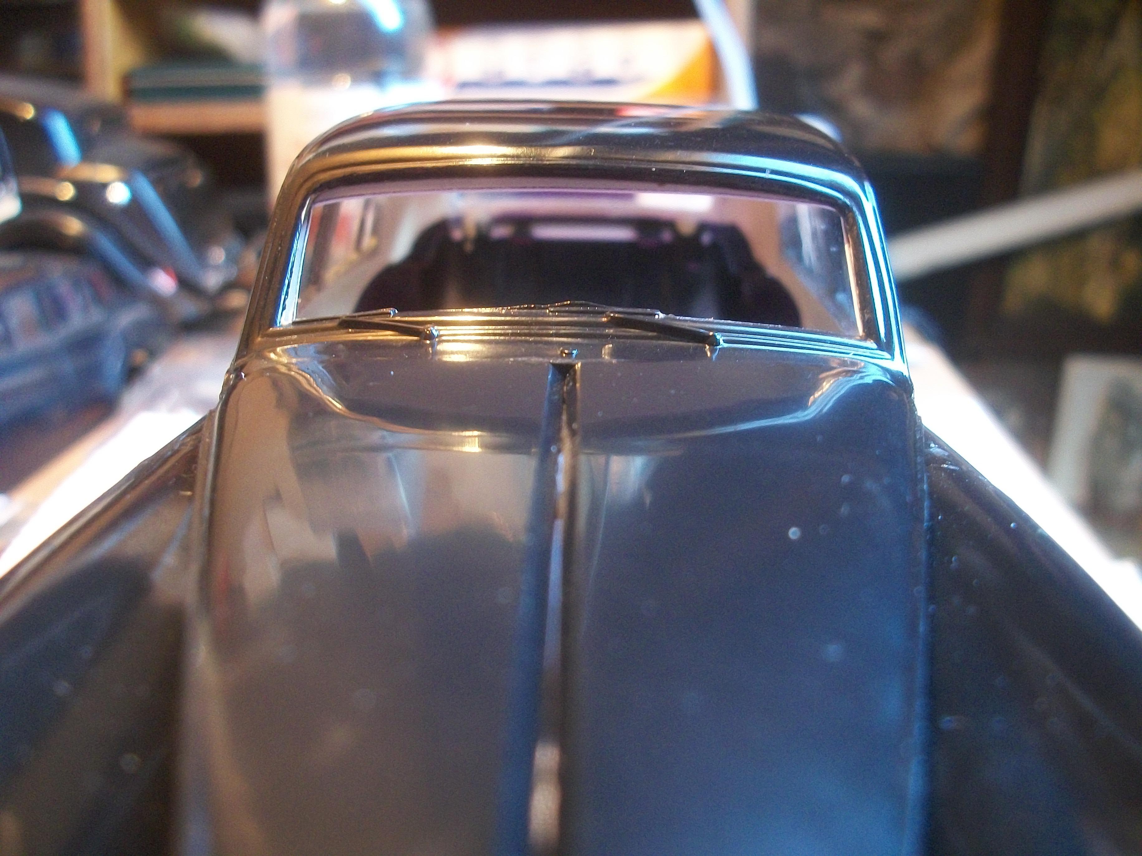
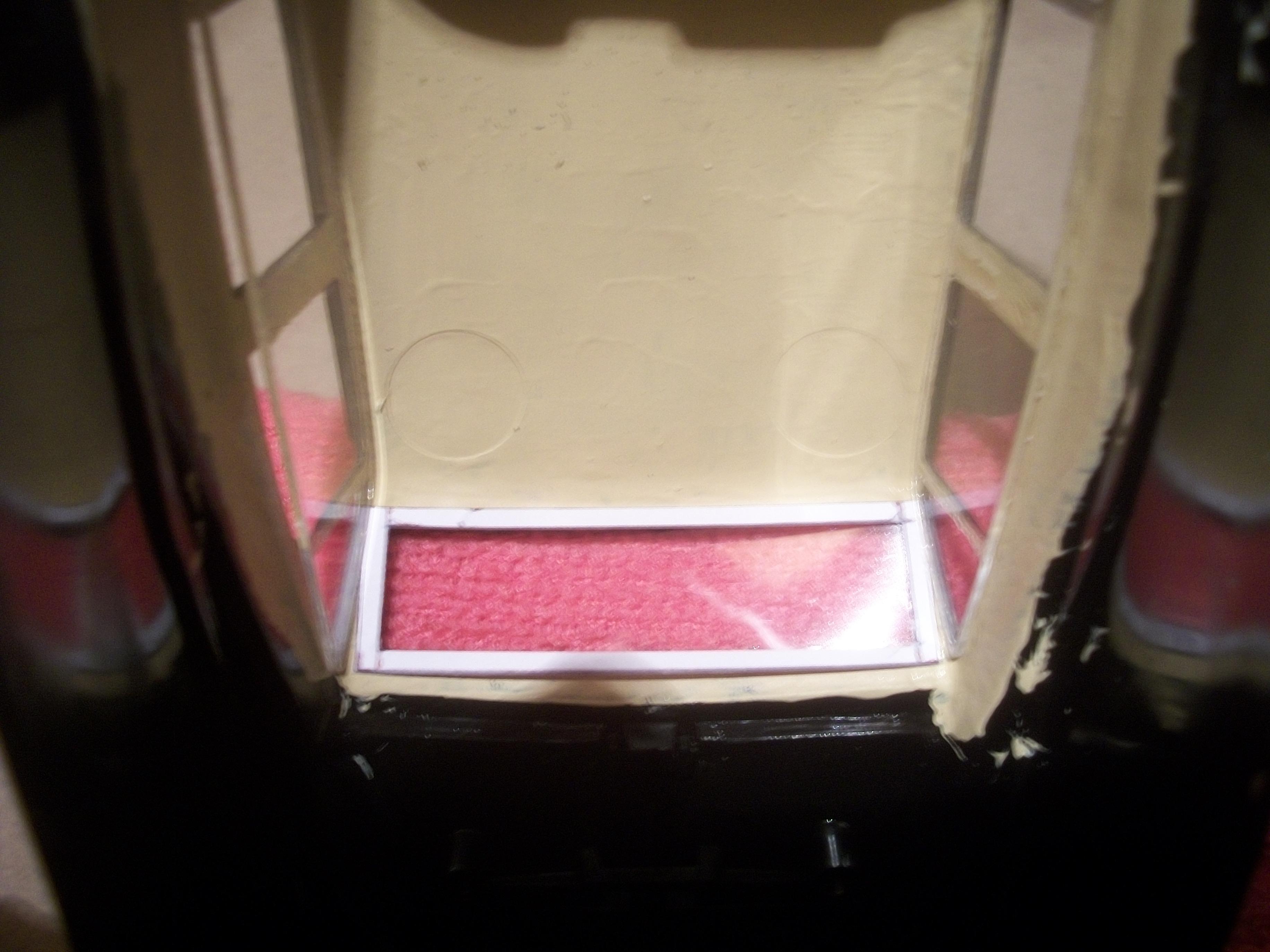
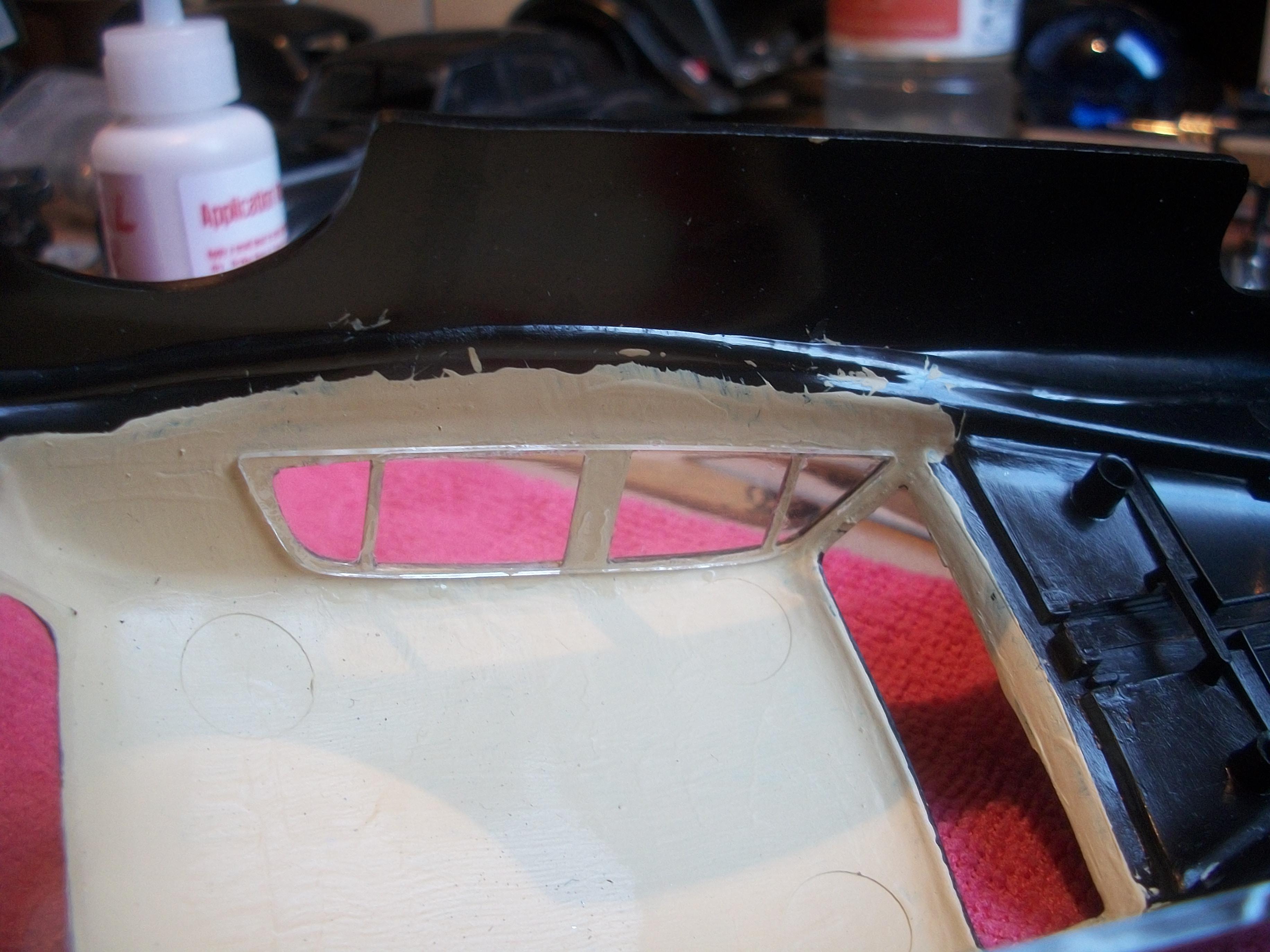
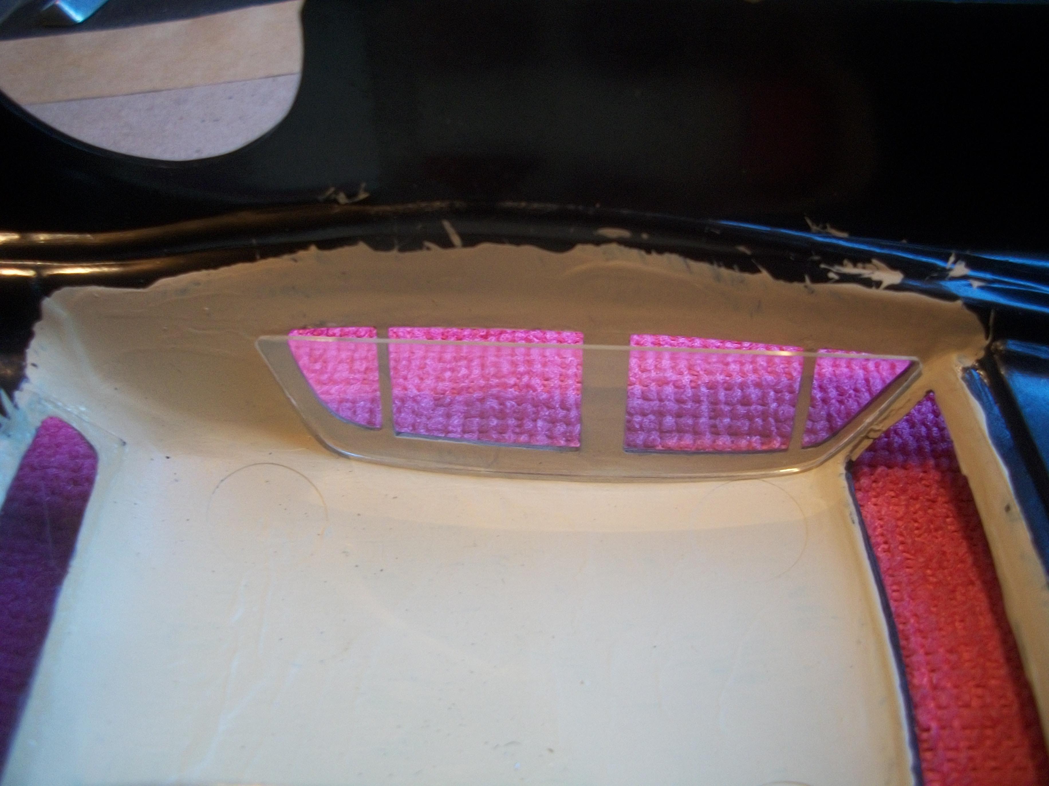
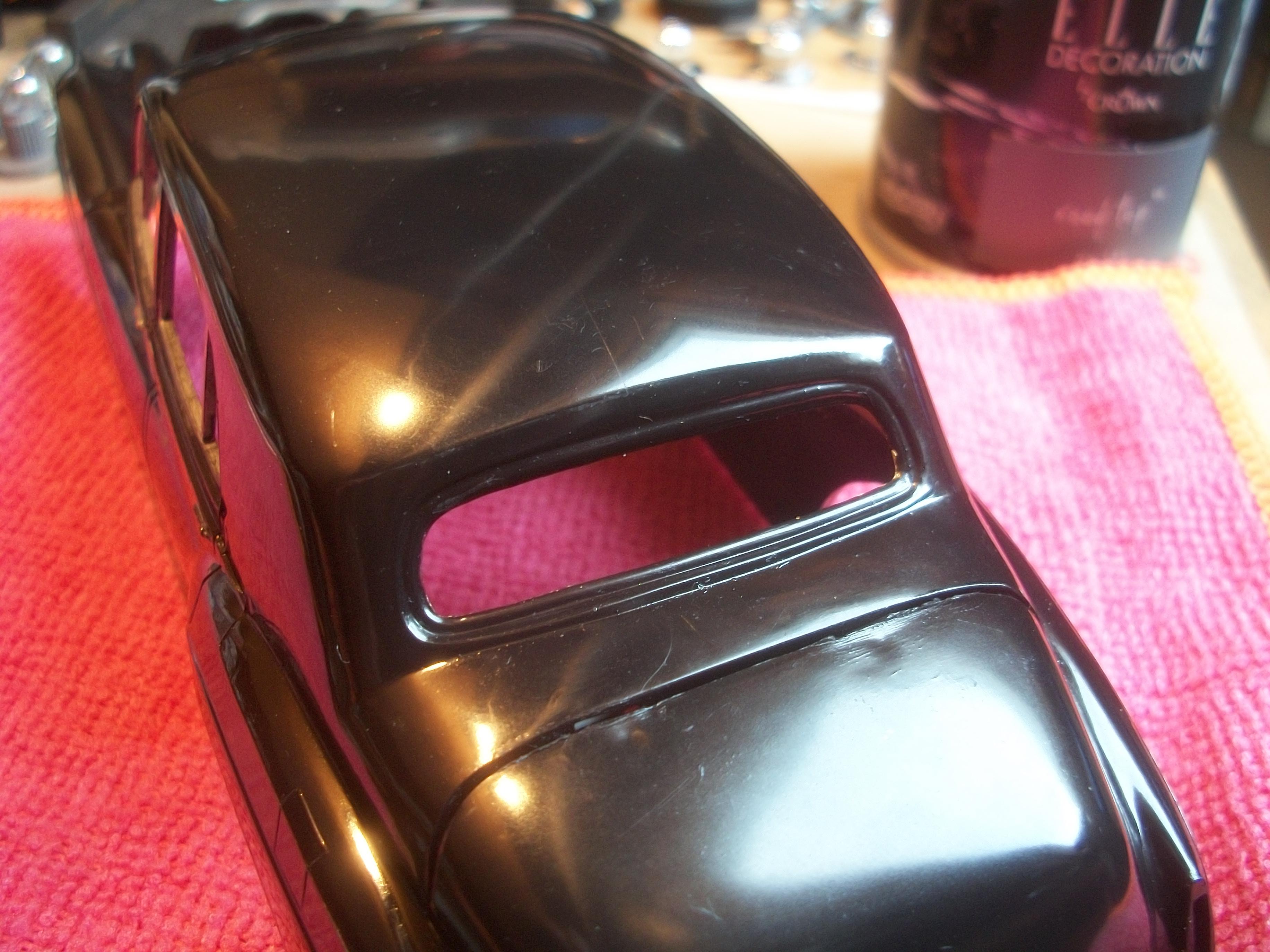
Before attempting to fit the windscreen / windshield for the first time, I finished off the polishing of the body. This included removing several scuff marks caused by handling, which were careless fingers touching silver Sharpie, and also removing the silver Sharpie strips along both sills. Later, I shall be using styrene rod for the sill mouldings, and these will be given the silver Sharpie treatment. The polish used was as before, the baking soda toothpaste applied with microfibre cloth. With a certain amount of anxiety and trepidation, I applied some Crystal Clear white glue to the surrounding area of the screen opening and allowed this to go tacky for a short while. The clear screen was eased into place, then the thin card inner frame was carefully positioned on top of the screen, which seemed to go into place nicely. At this point things started to go wrong . . . The screen refused to line up correctly and I struggled with a gap of around one millimeter that just would not cooperate. During the struggle the frame and the screen both suffered damage. Shortly after this failure I gave up and pulled out the two parts. I need to come back to this idea with a fresh approach, or even find an alternative method. Maybe I am trying to be too clever here? David
-
Rolls-Royce No Chemicals, No Paint, No Harmful Glues
Anglia105E replied to Anglia105E's topic in WIP: Model Cars
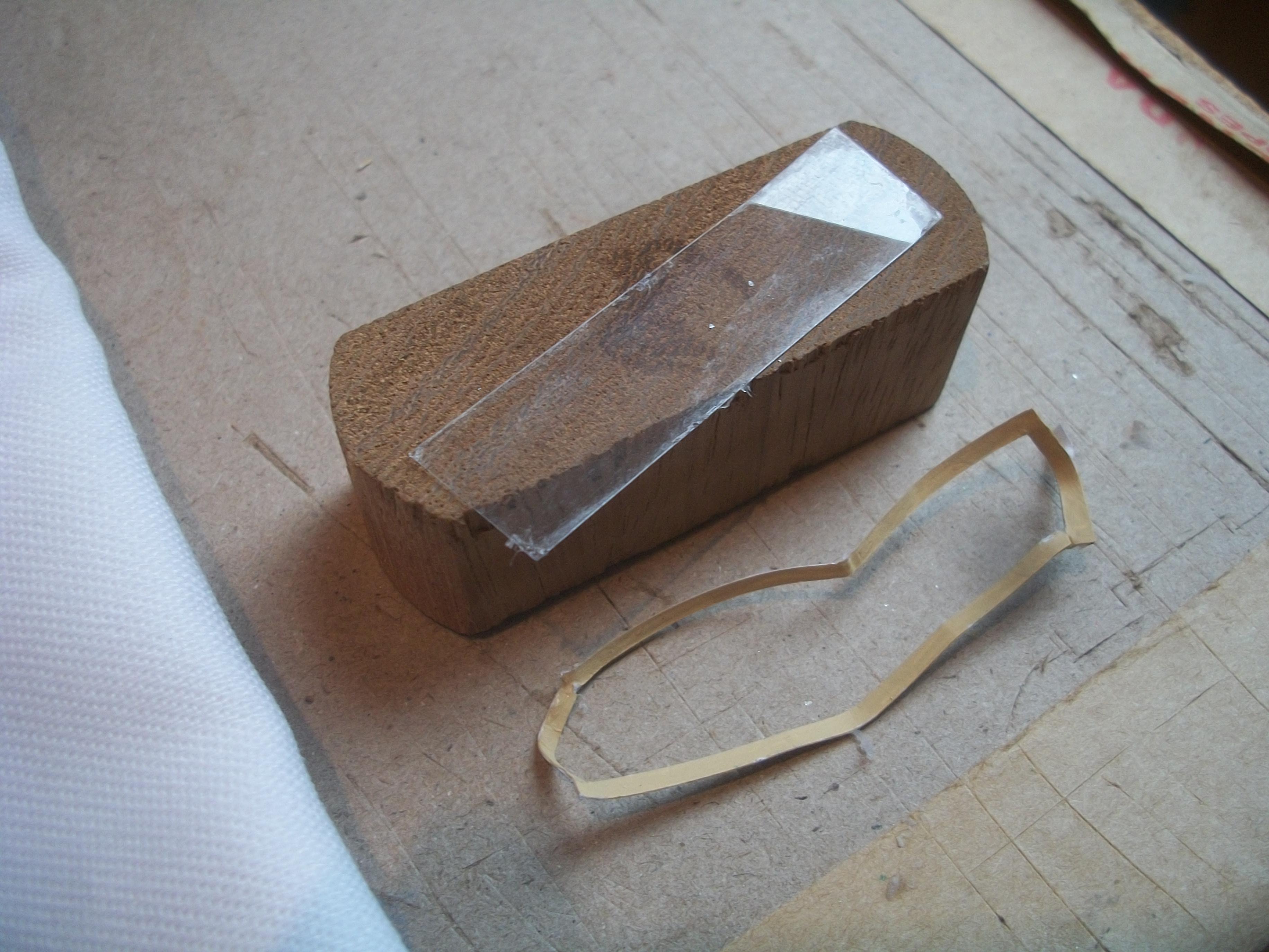
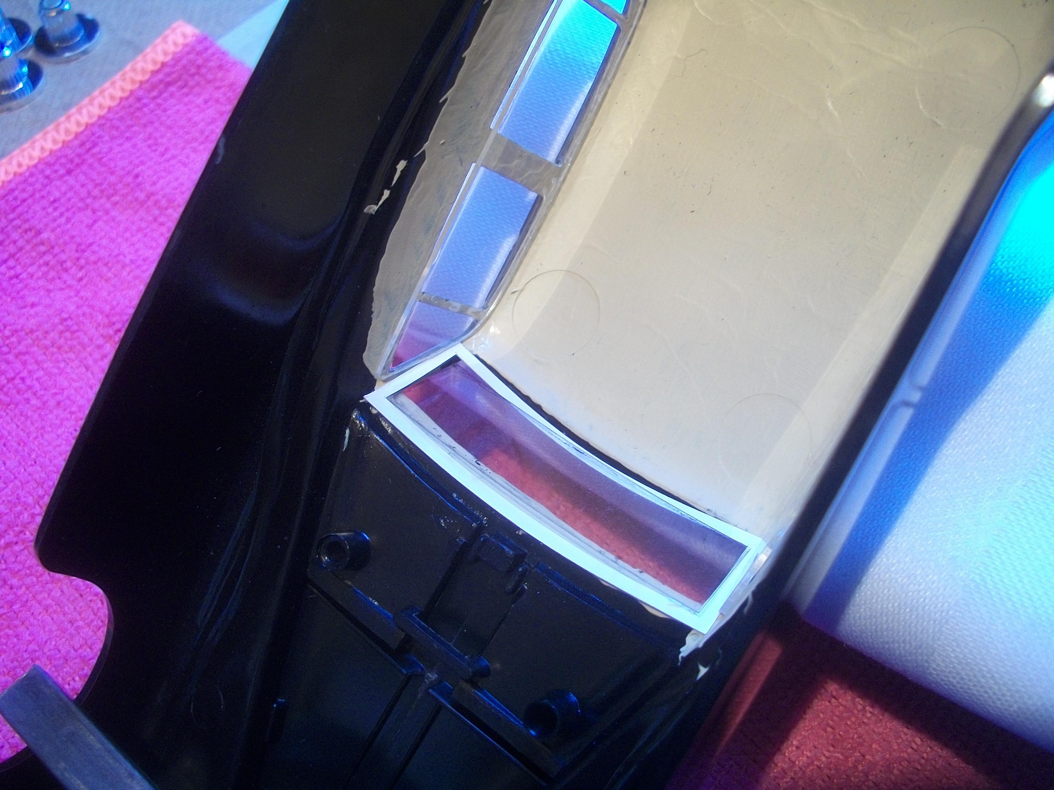
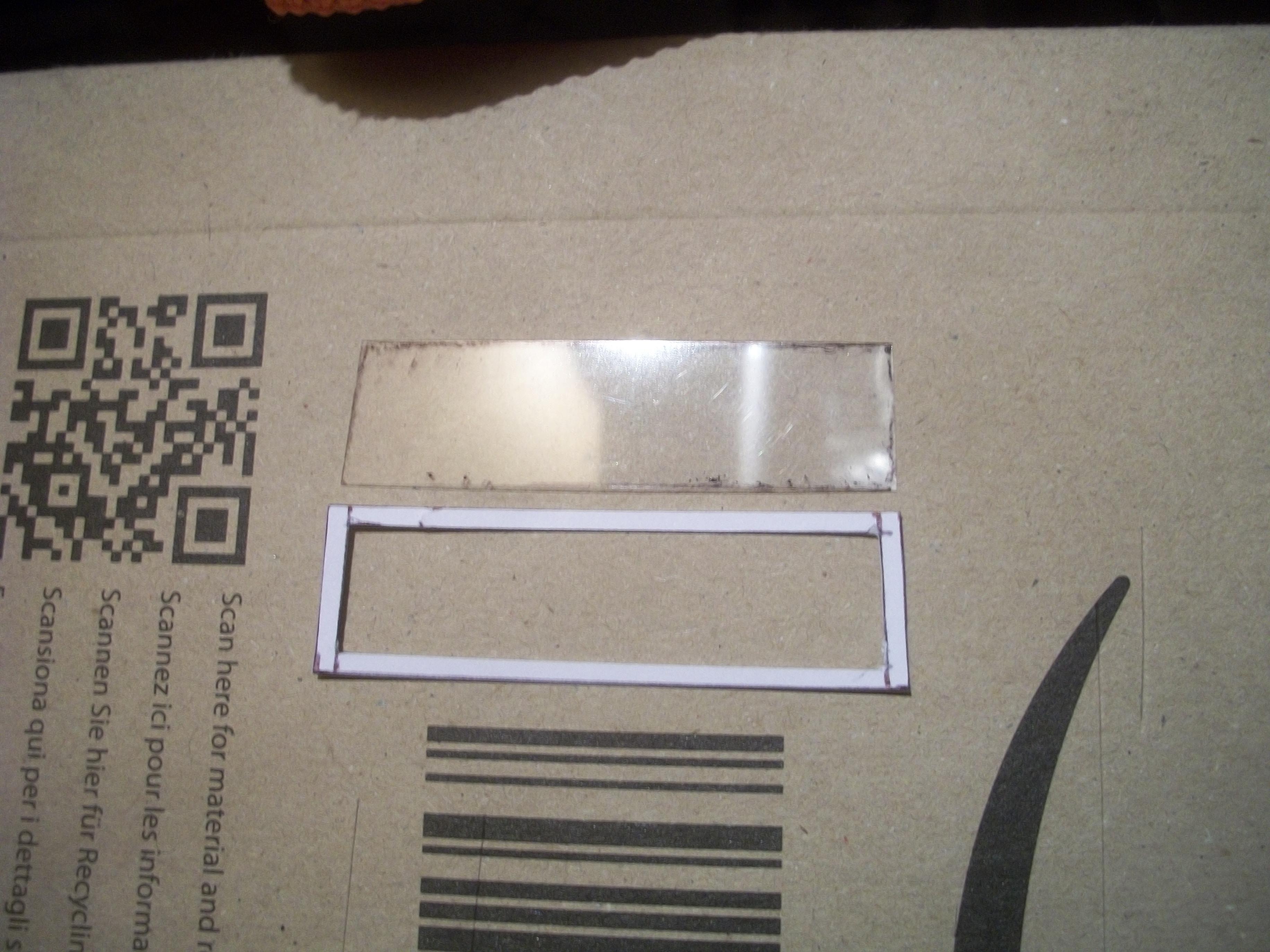
Although I seem to have managed to get a good fit on the inner card frame, the same cannot be said for the clear film screen. There is no margin for error with this part . . . Half a millimeter too large, or half a millimeter too small in either direction, and the screen will not fit into the opening of the body. I knew it would be that precise when I set out to make it fit, so no surprise really. David -
Rolls-Royce No Chemicals, No Paint, No Harmful Glues
Anglia105E replied to Anglia105E's topic in WIP: Model Cars
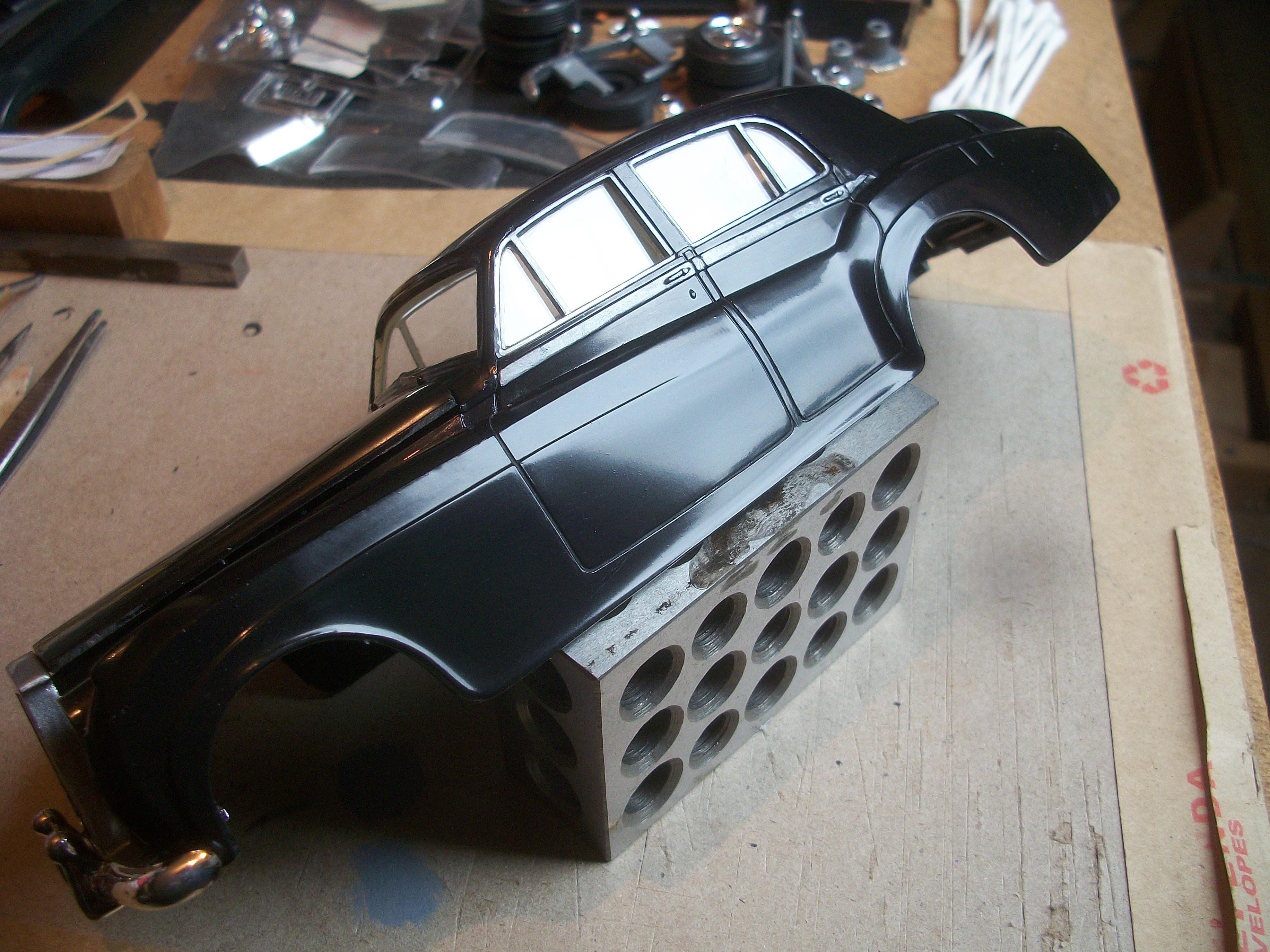
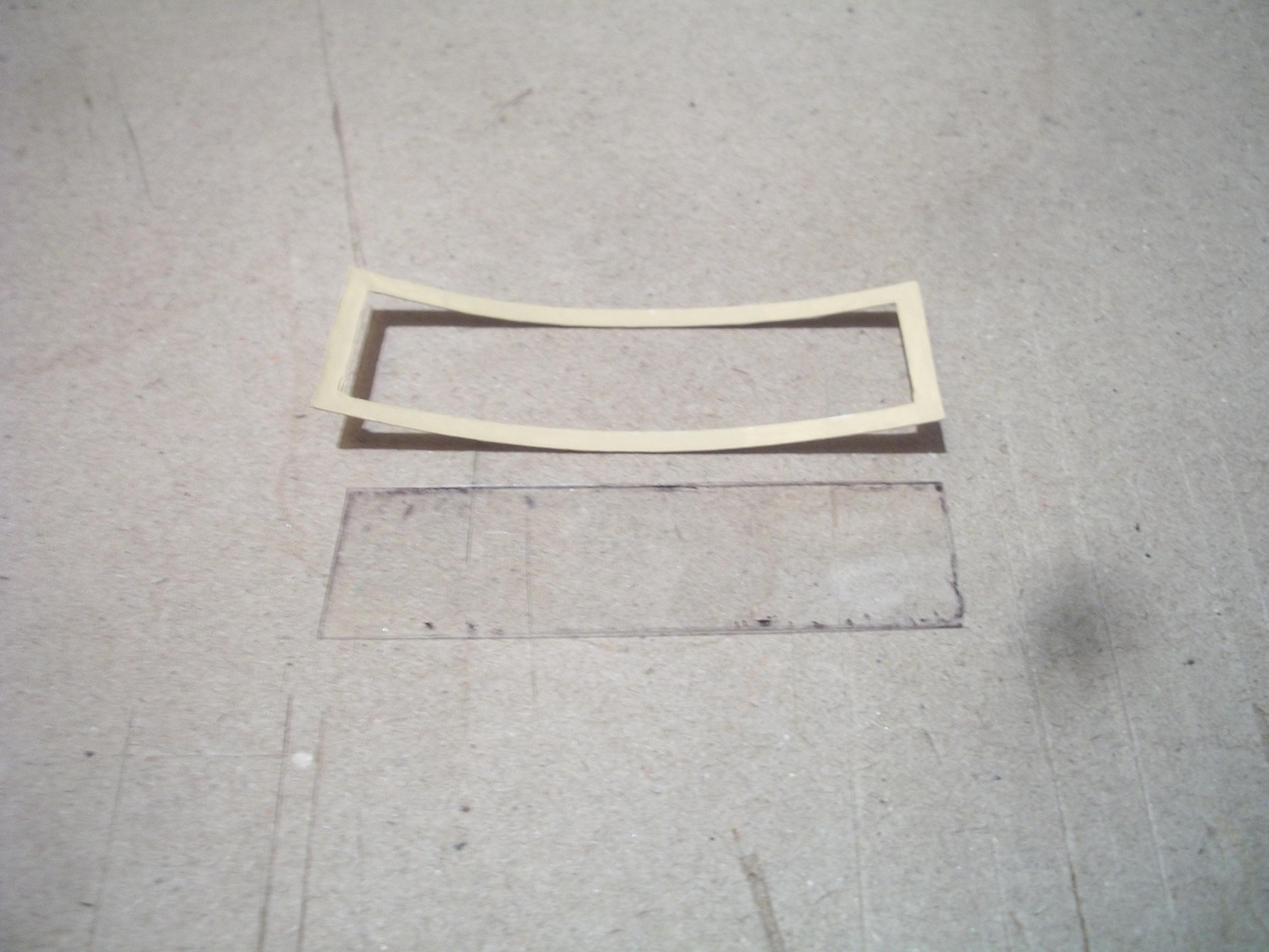
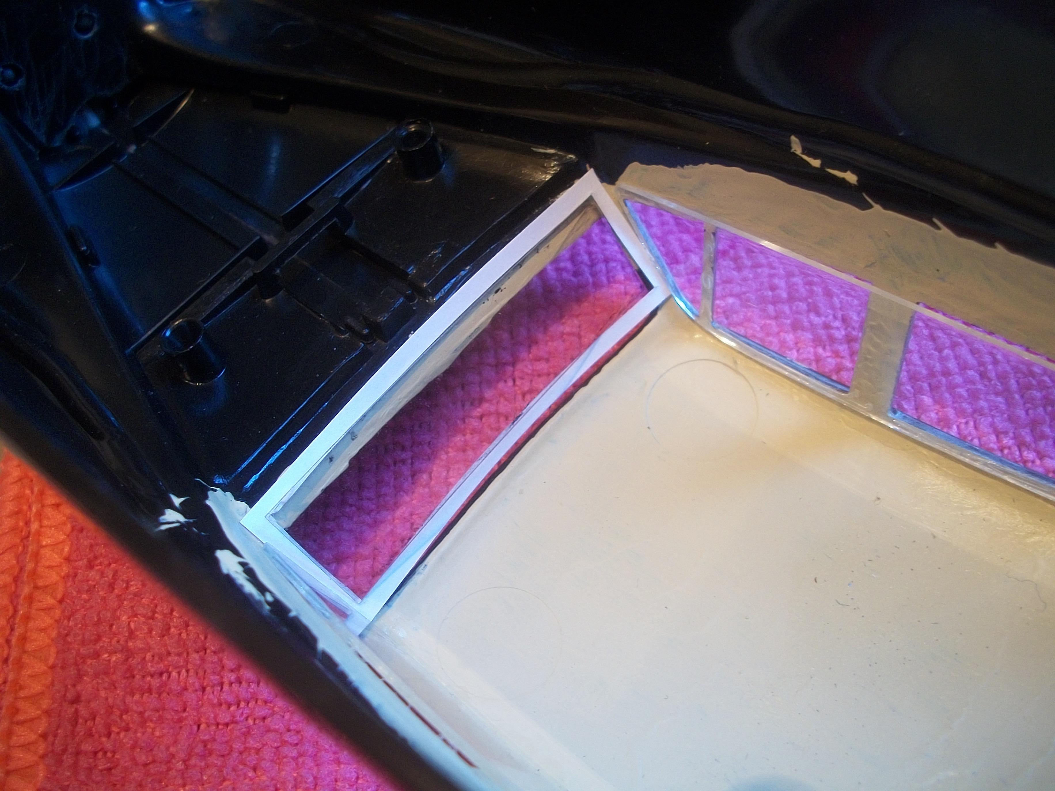
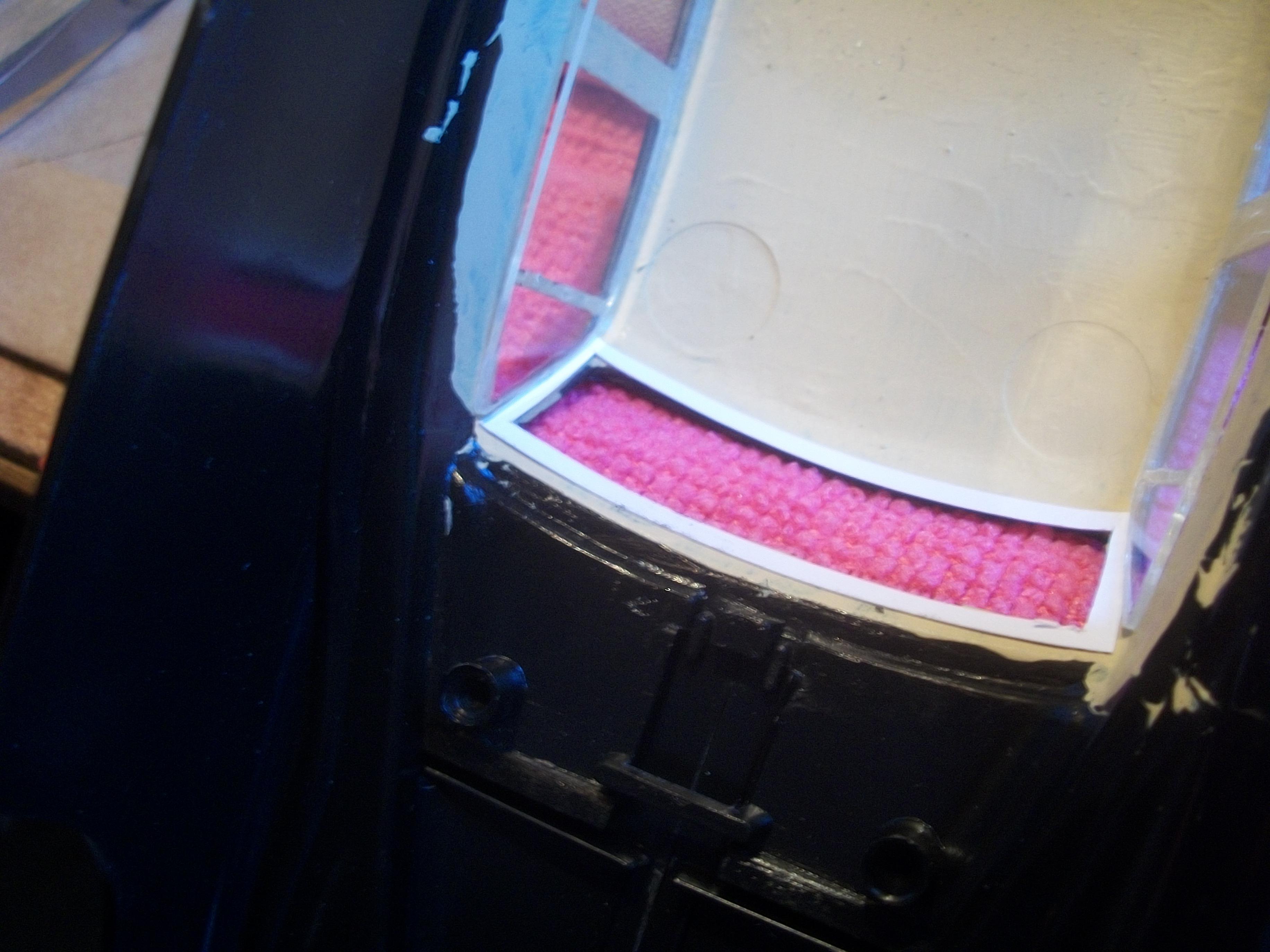
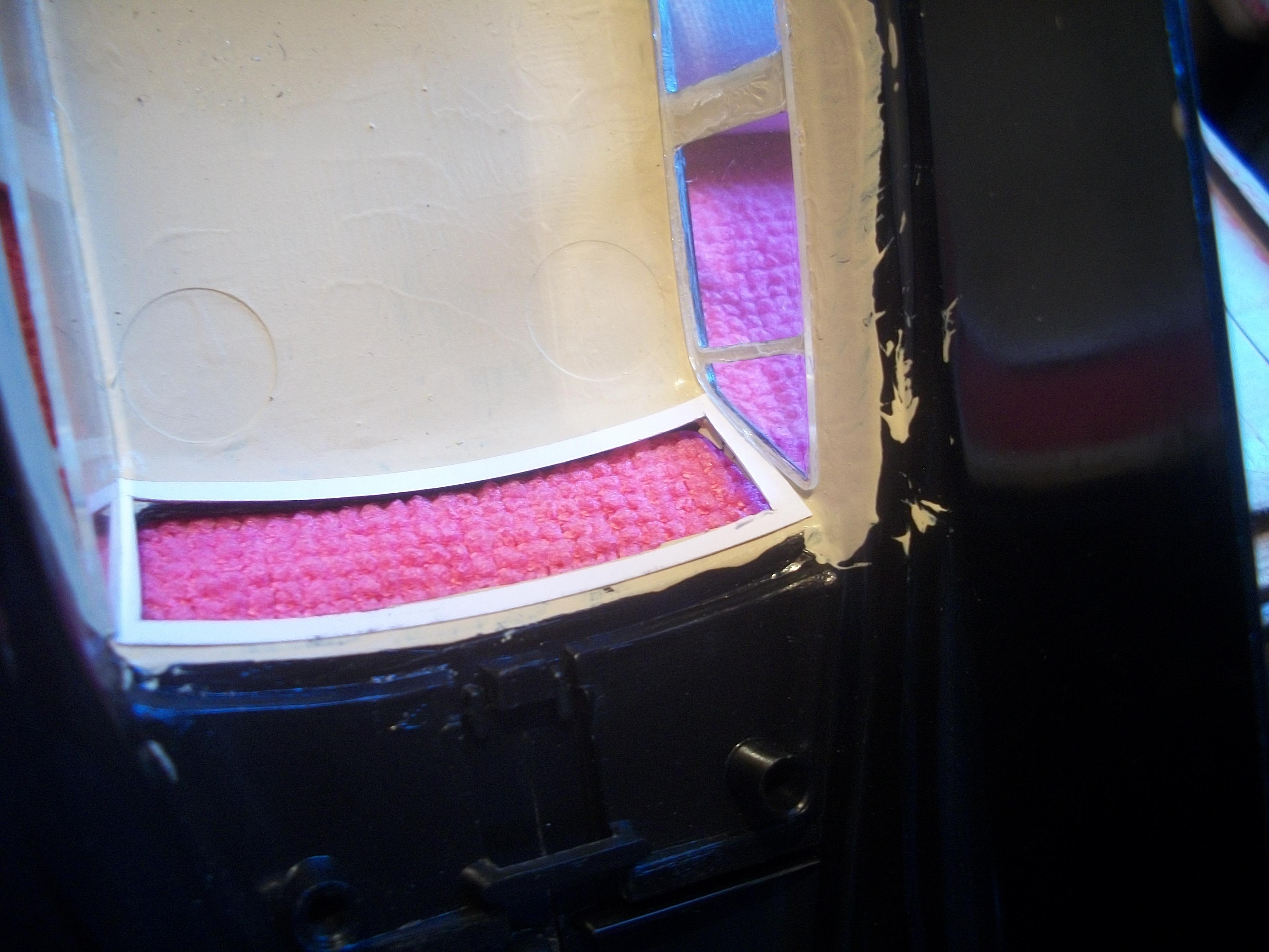
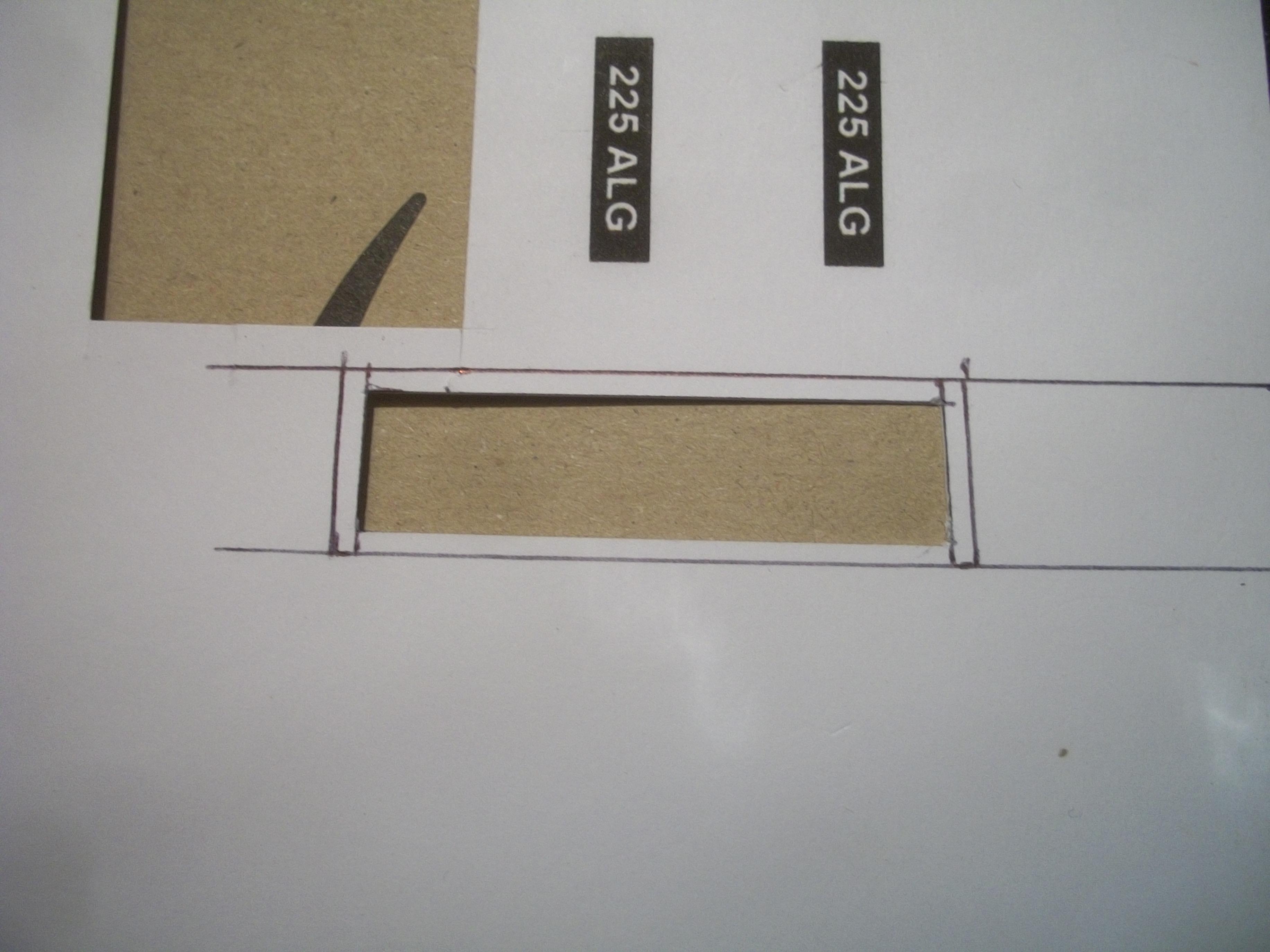
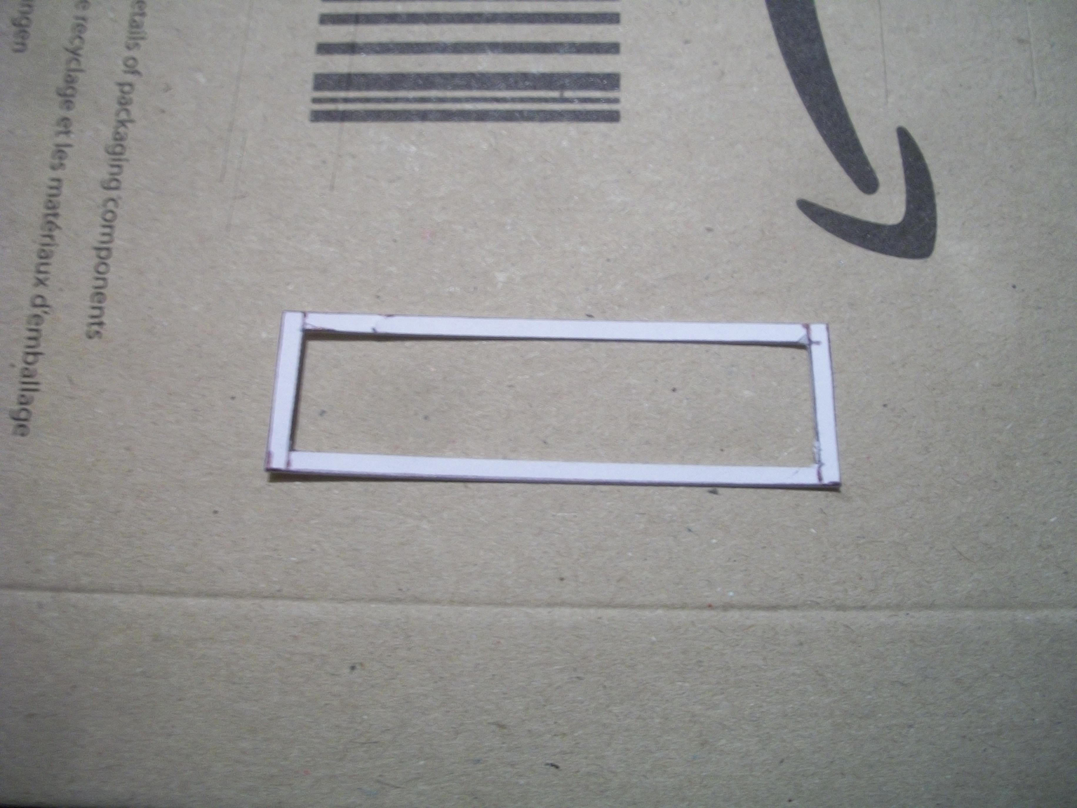
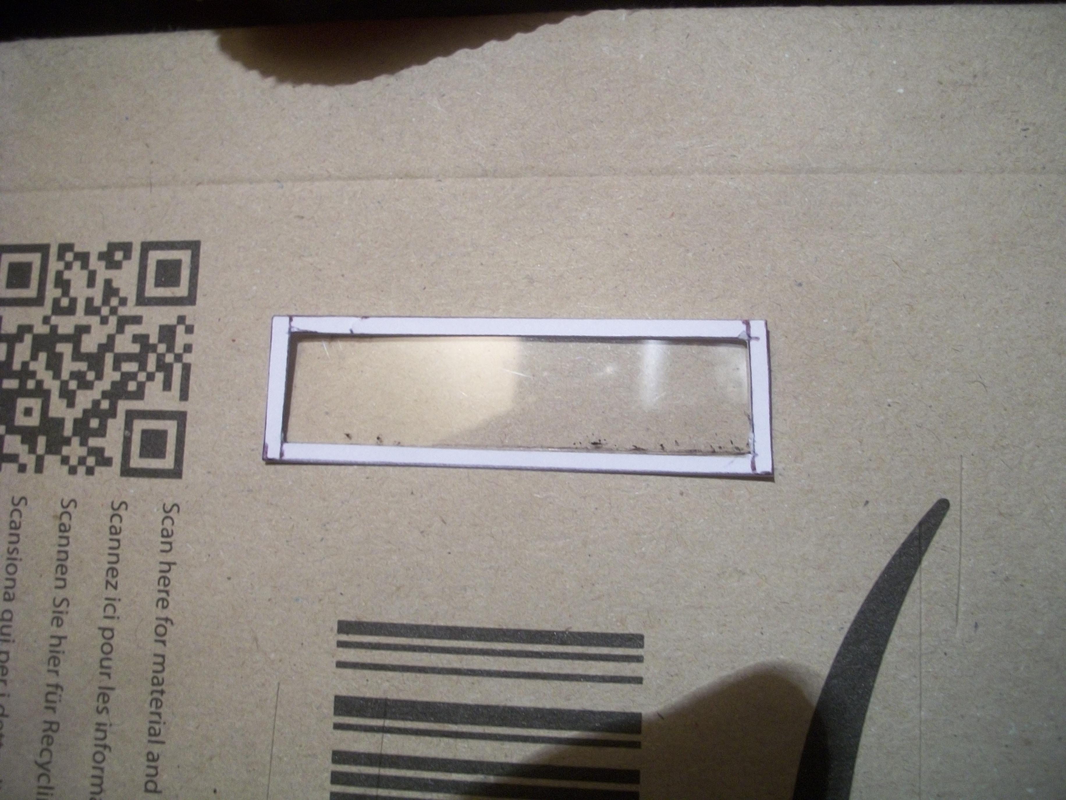
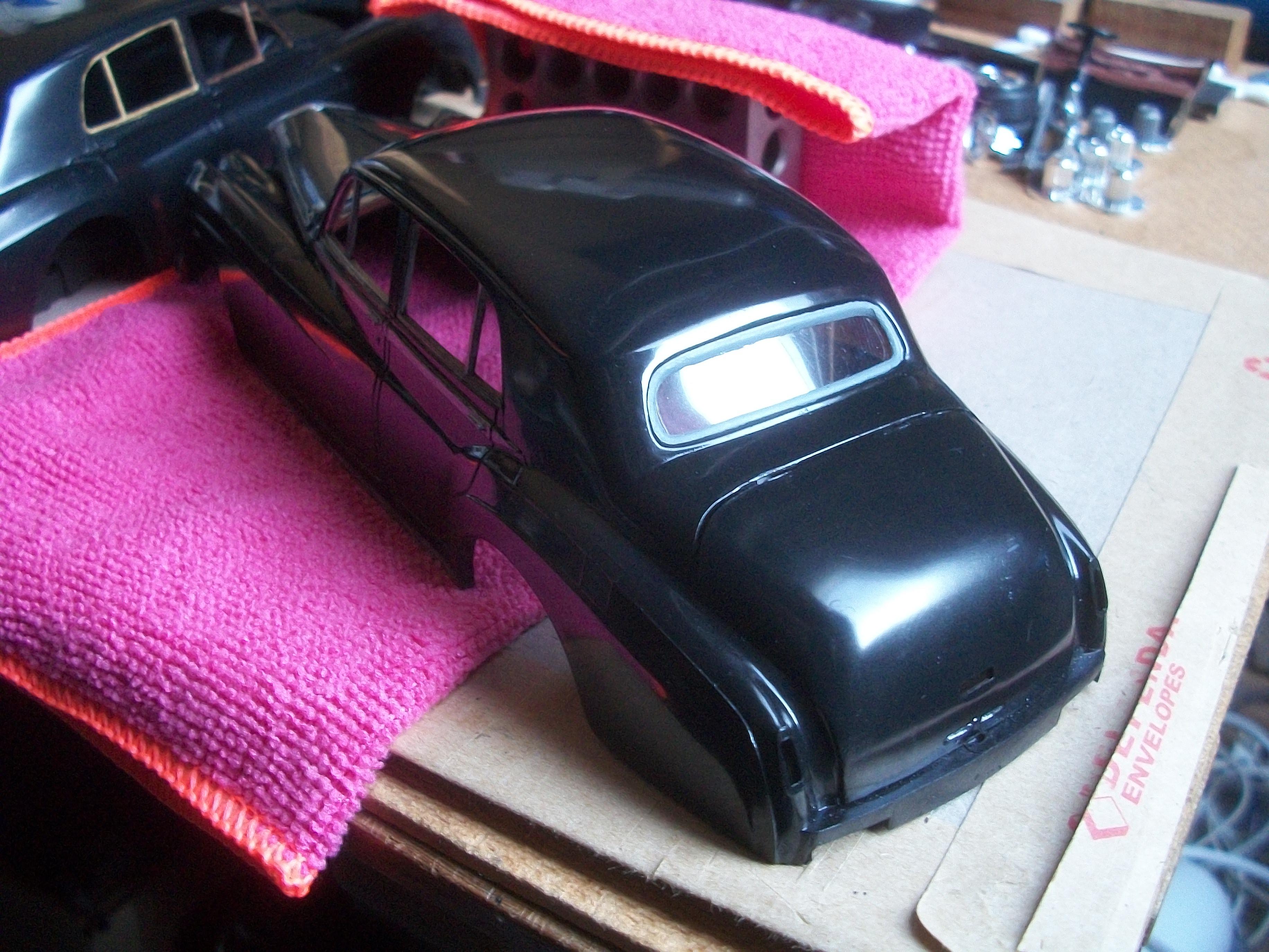
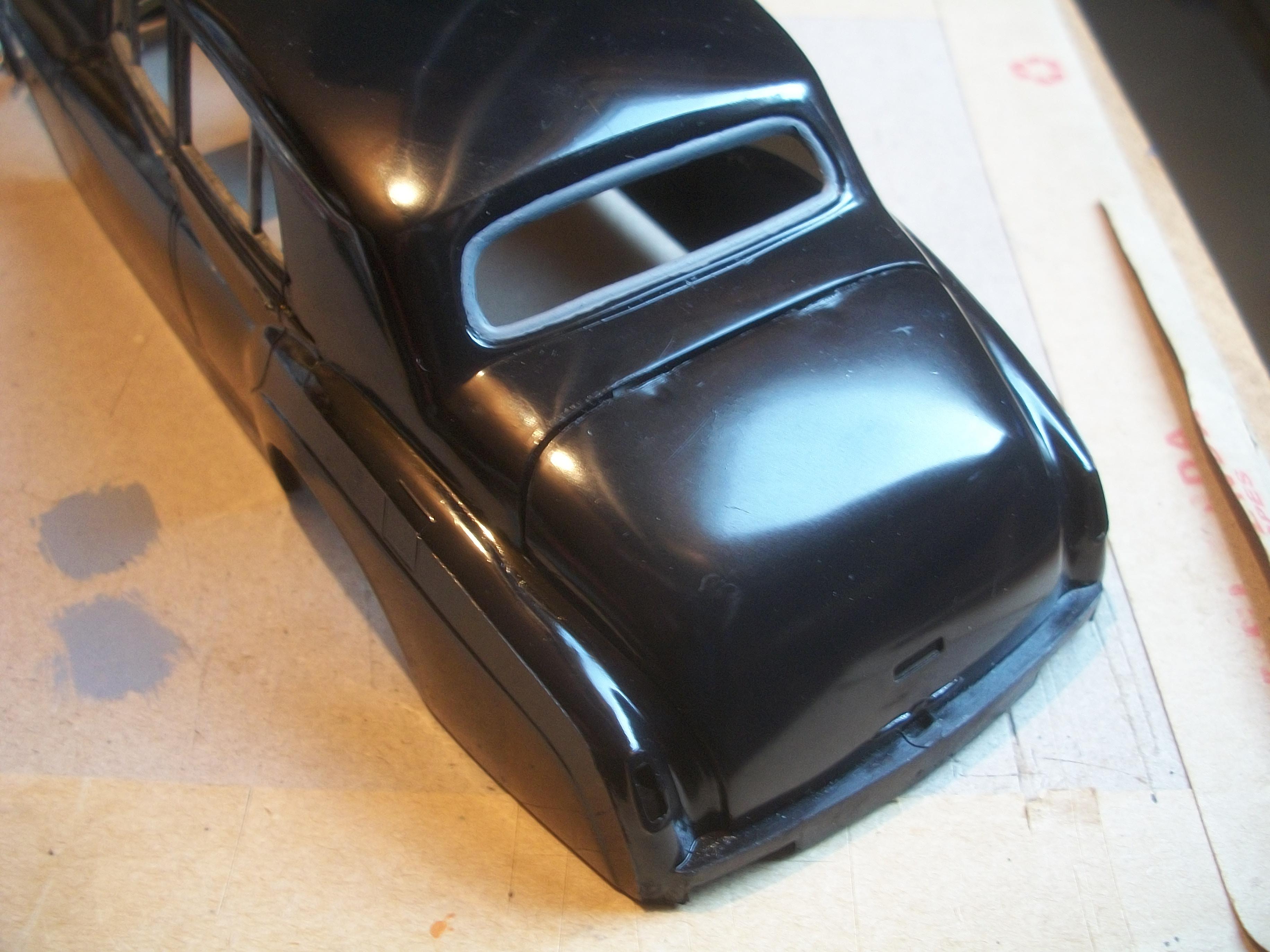
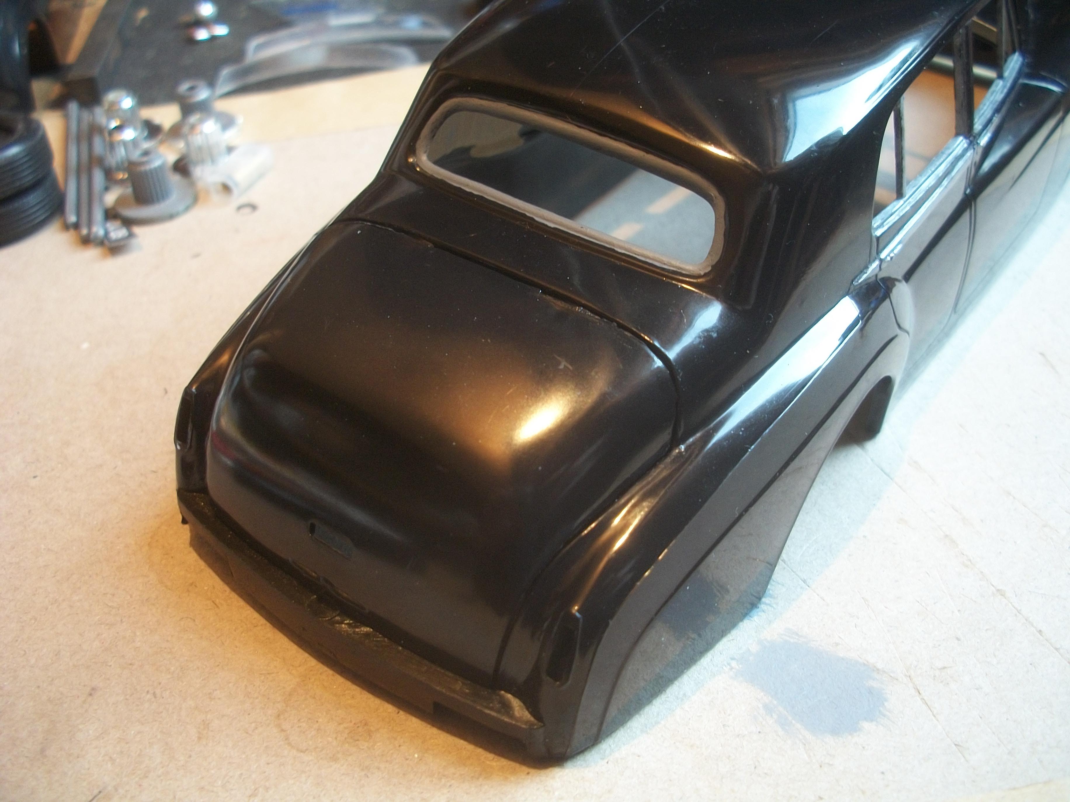
On closer examination, the inner frame that was cut from thin white card was actually too small . . . This was duly rectified by measuring and cutting out a slightly larger frame, which now has a very precise fit. Without having painted the frame with the headlining colour just yet, here are a few photos showing the recent progress . . . It remains to be seen how the edges of the clear film screen will fit into the opening of the body, and also how well they will mate up to the inner edges of the frame. What is interesting from my point of view, is how the thin card has bent upwards when the emulsion paint was applied, and the curvature of this card frame seems to match the same curvature of the real car screen ! David
-
Rolls-Royce No Chemicals, No Paint, No Harmful Glues
Anglia105E replied to Anglia105E's topic in WIP: Model Cars
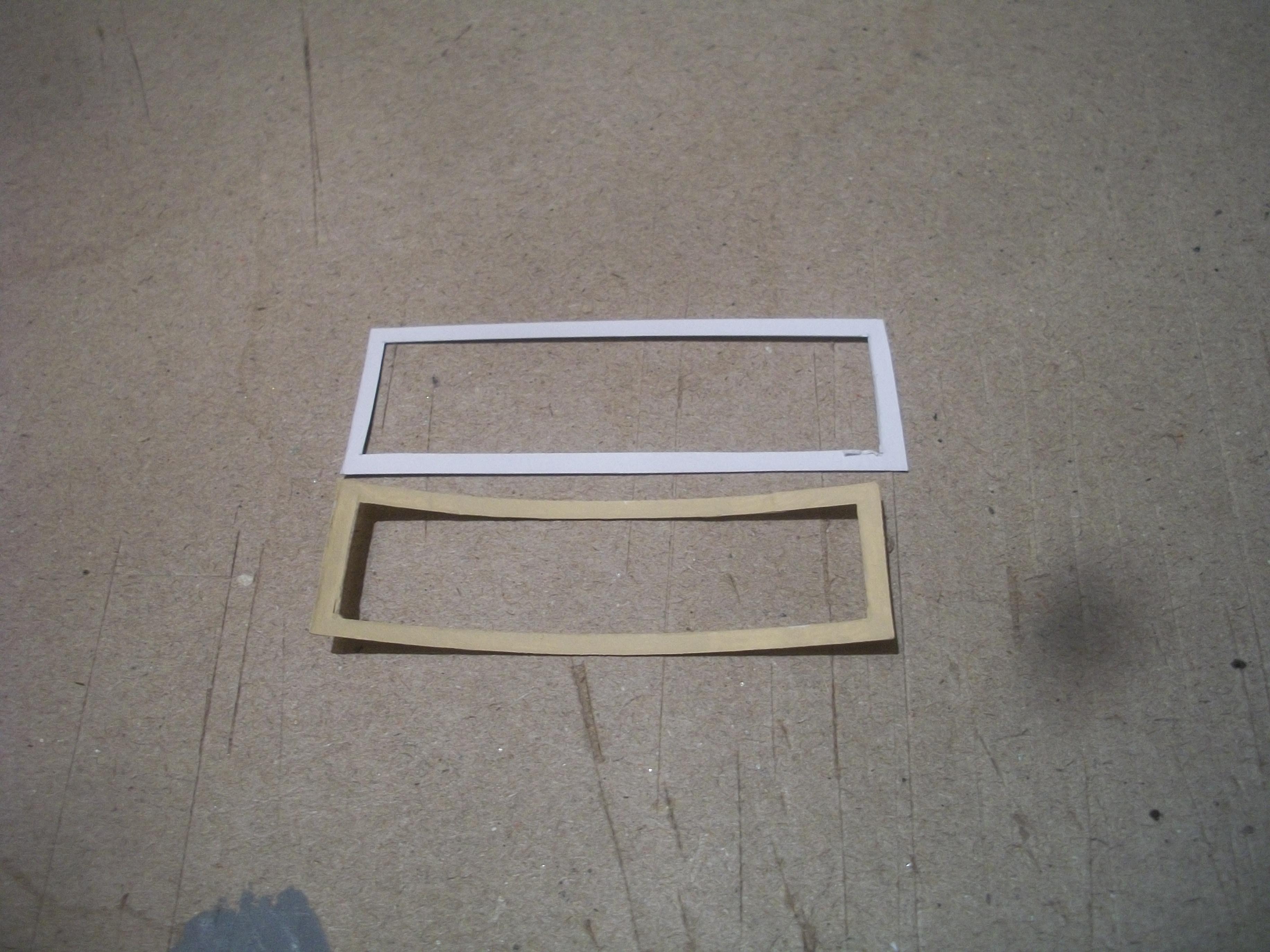
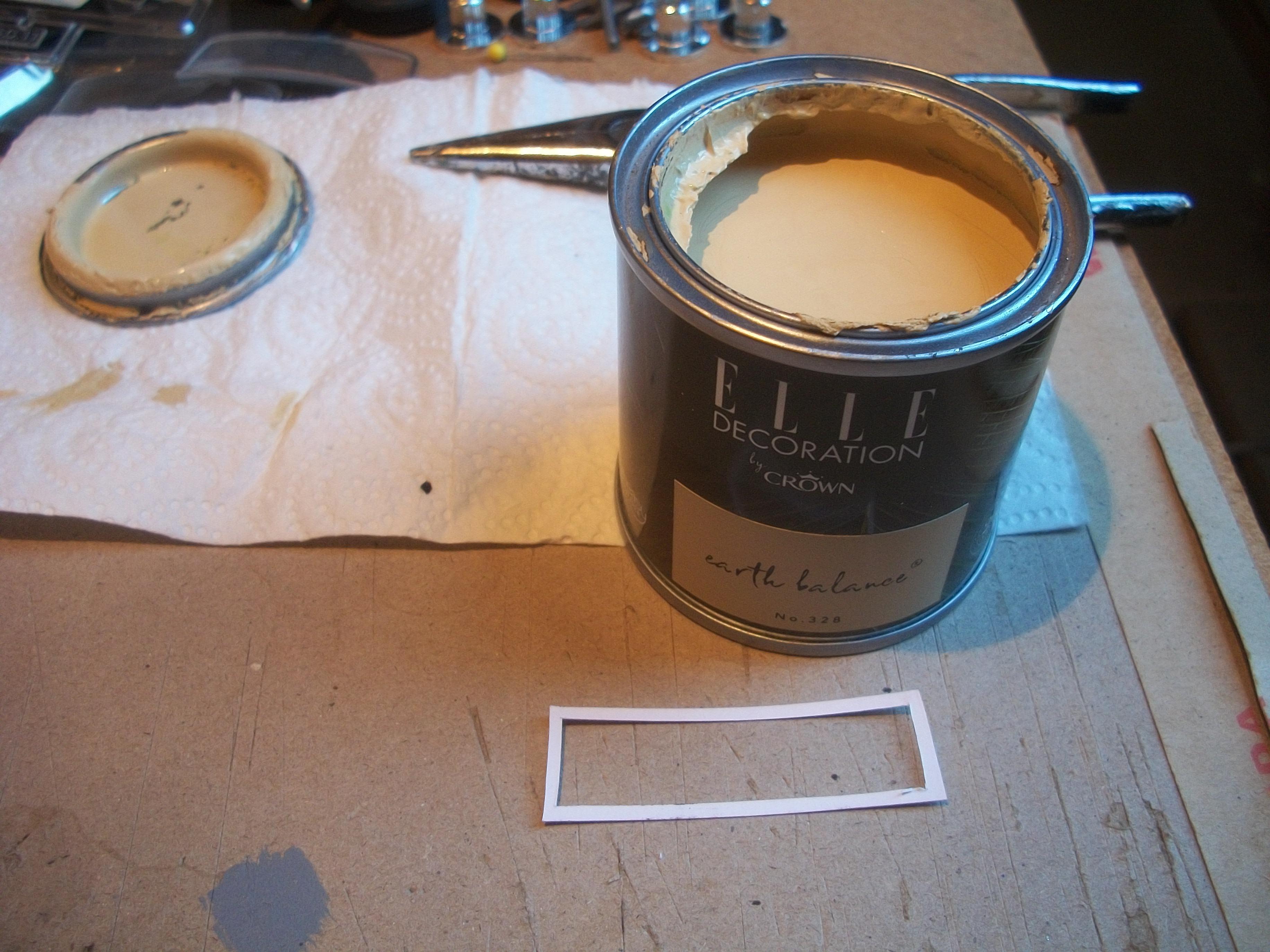
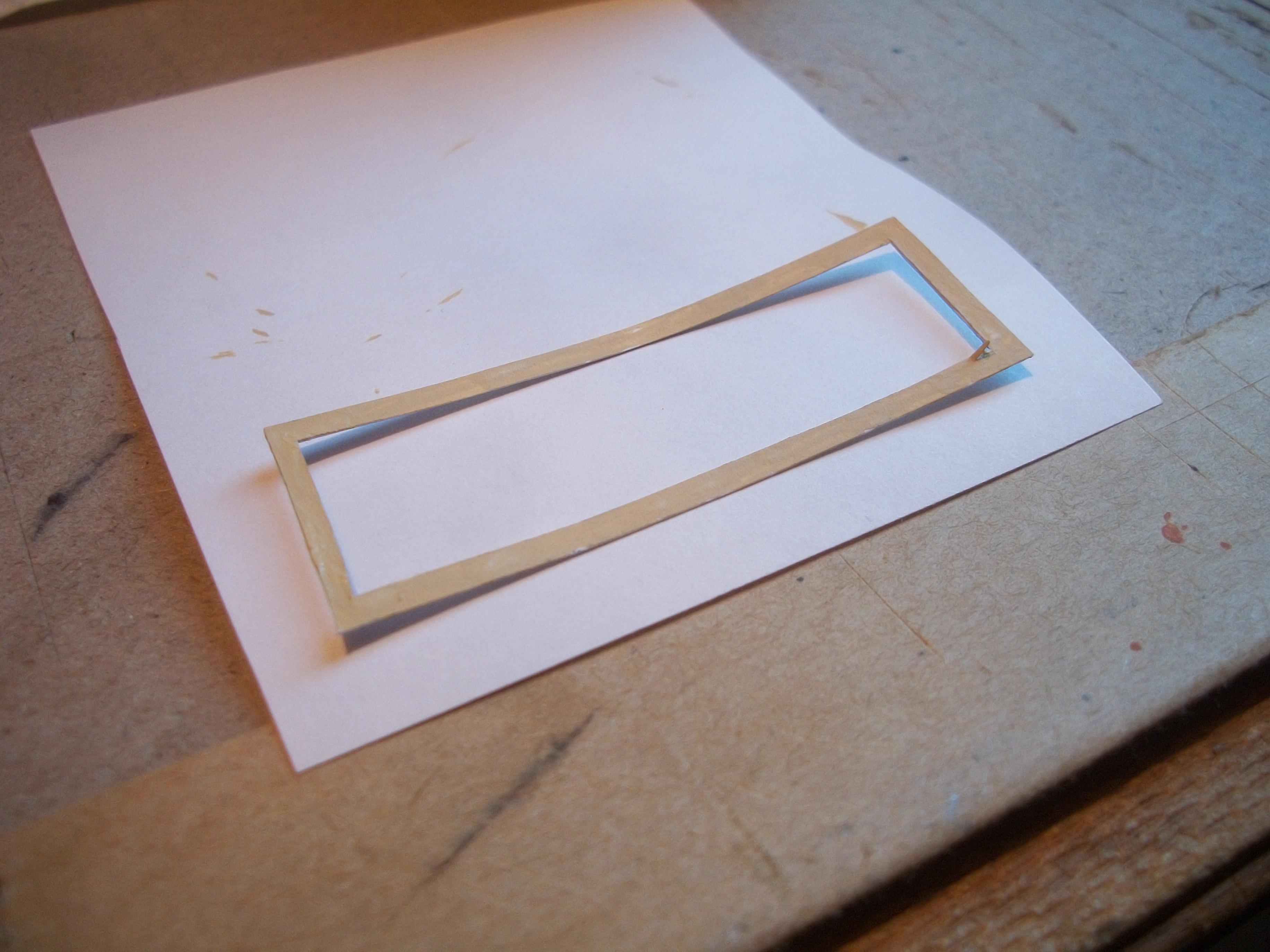
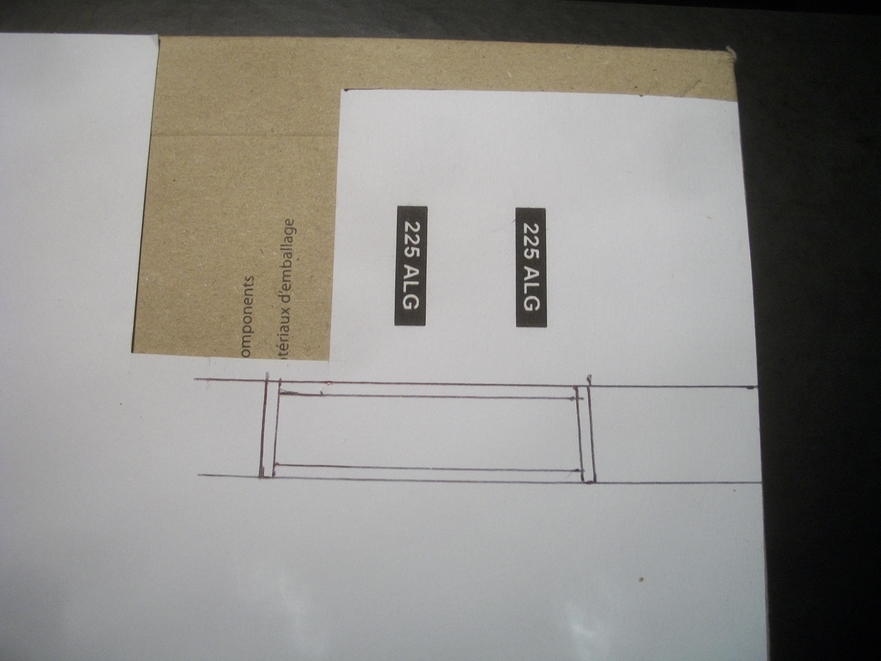
Following some careful calculations and measuring, I have cut out the front screen from thin clear film, and also cut out the inner frame from thin white card. The inner frame will be painted the same colour emulsion as the headlining . . . The screen glass will be glued in place using Crystal Clear white glue, while the inner frame will be fitted over the edges of the screen from the inside of the body, using washable PVA glue. This is the first time that I have tried this technique to fit a windscreen / windshield, so I am not sure what to expect . . . This idea just came into my head. David
-
Rolls-Royce No Chemicals, No Paint, No Harmful Glues
Anglia105E replied to Anglia105E's topic in WIP: Model Cars
Thanks Mark, and I do have both Evergreen and Plastruct styrene products in my bag of stuff up in the loft. Without checking, I think I have half round, also square rod and round rod, styrene sheet in various thicknesses, and some girders and roof trusses too . . . Thanks anyway for the tip. David -
Rolls-Royce No Chemicals, No Paint, No Harmful Glues
Anglia105E replied to Anglia105E's topic in WIP: Model Cars
Sorry Mark, I haven't explained this properly . . . There are no mouldings as such, so all I have done is to run the silver Sharpie along the length of the sill area to create the illusion of a chrome moulding . . . Basically, I ran the Sharpie along the lower body twice, to create a fairly wide strip, whereas what this needs is the Sharpie only needs one thin run along the lower edge of the sill. I hope that is a clearer description of what I am trying to do ! I could of course glue a length of thin styrene rod onto the bottom edge of the sill, and then give it a coat of silver Sharpie . . . Actually, that would look better. David -
Rolls-Royce No Chemicals, No Paint, No Harmful Glues
Anglia105E replied to Anglia105E's topic in WIP: Model Cars
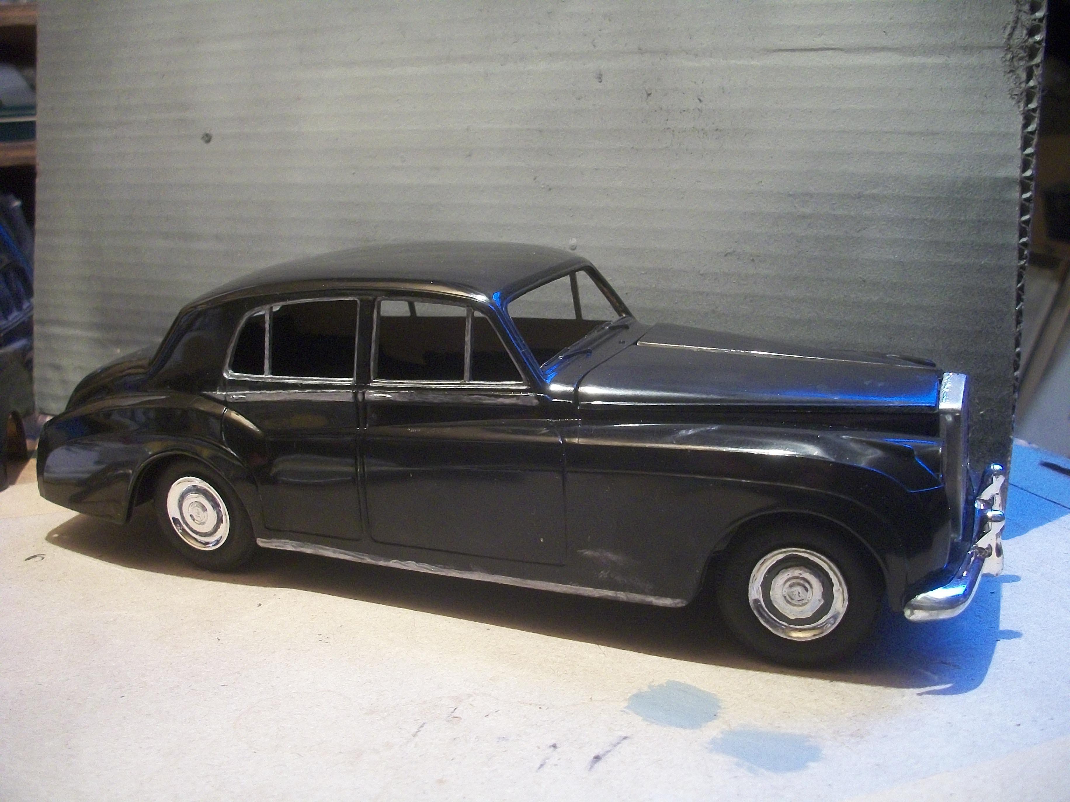
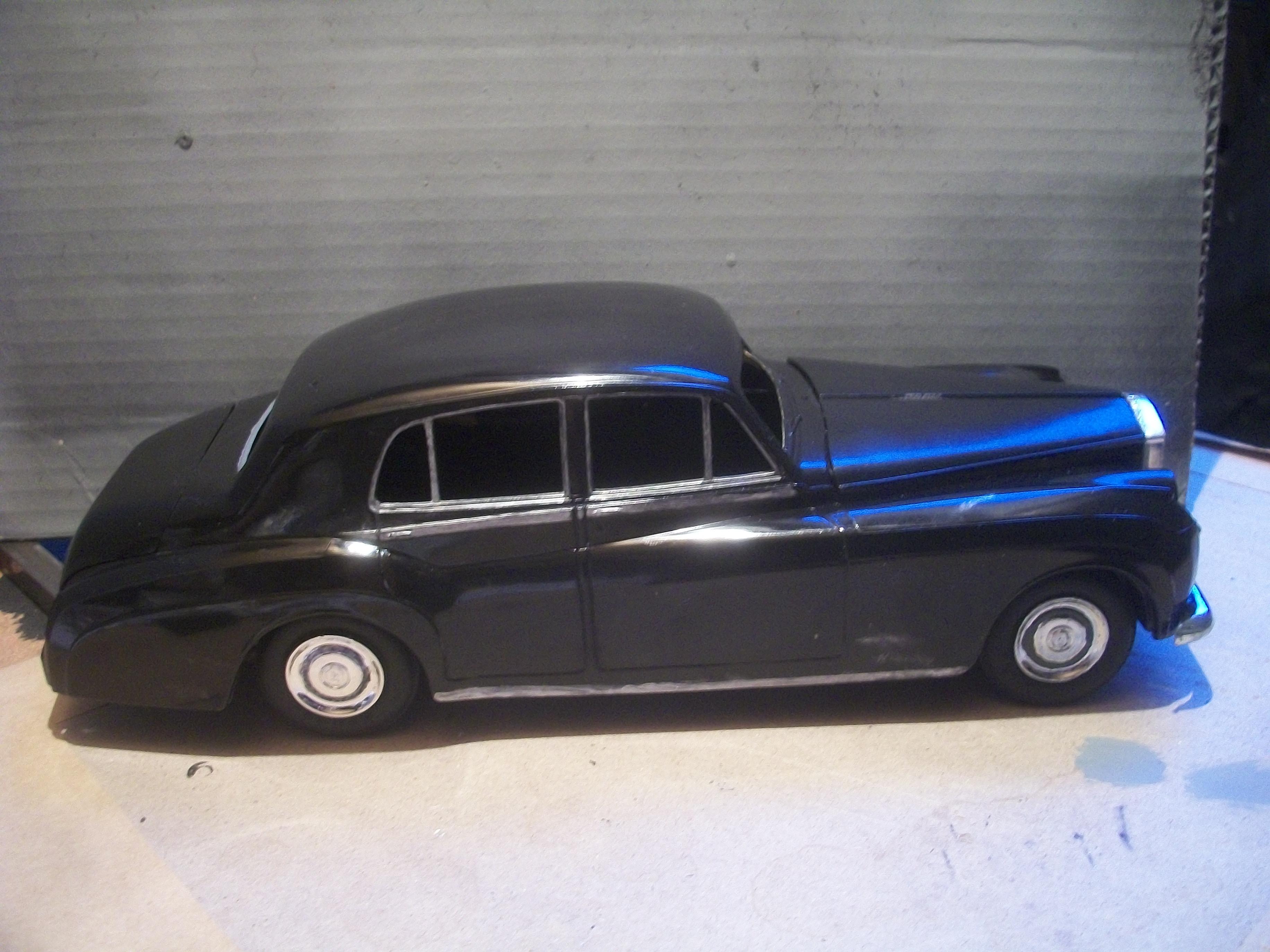
I need to source the Quick Shine product, which will probably be from Amazon as it is not available from anywhere else. Yesterday I noticed that the sill mouldings on the full size real car are much more narrow than I have made them on the model, so the silver Sharpie needs to be removed and re-done. The chrome strips should be around half the width to be accurate . . . ( see following photos ) David
-
Liking it so far Mark . . . Yes, when I was much younger I did construct model aircraft from balsa and tissue, and I remember the " dope " that was used to make the tissue stretch into a hard material, and dope had a very strong smell as well being highly inflammable ! The aircraft were flown by control line, as opposed to radio control and they had small glo-plug petrol engines if I remember correctly . . . Also, I have constructed the 1:43 scale factory building using square styrene rods and sheets of strong card and styrene, more recently. David
-
Sounds like a good plan Mark . . . This is one of many reasons why I like building the Rolls-Royce Silver Cloud models, because there has only been one manufacturer of the kit ( Minicraft ), and only in one scale ( 1:24 ), and the only diecast available is the Franklin Mint 1:24 scale model, which is a nice version of a Silver Cloud I but the Spirit of Ecstasy hood mascot is always missing from the ones on Ebay . . . I enjoy building the kit from Hubley, Minicraft, Revell, Entex and others, rather than simply buying the ready made diecast. Those Franklin Mint models of this car are still selling for quite high prices, especially when you consider how long they have been around. Your upcoming project sounds really interesting, and I do understand how it feels to be thinking of the next build, even before the current build is actually completed . . . David
-
Rolls-Royce No Chemicals, No Paint, No Harmful Glues
Anglia105E replied to Anglia105E's topic in WIP: Model Cars
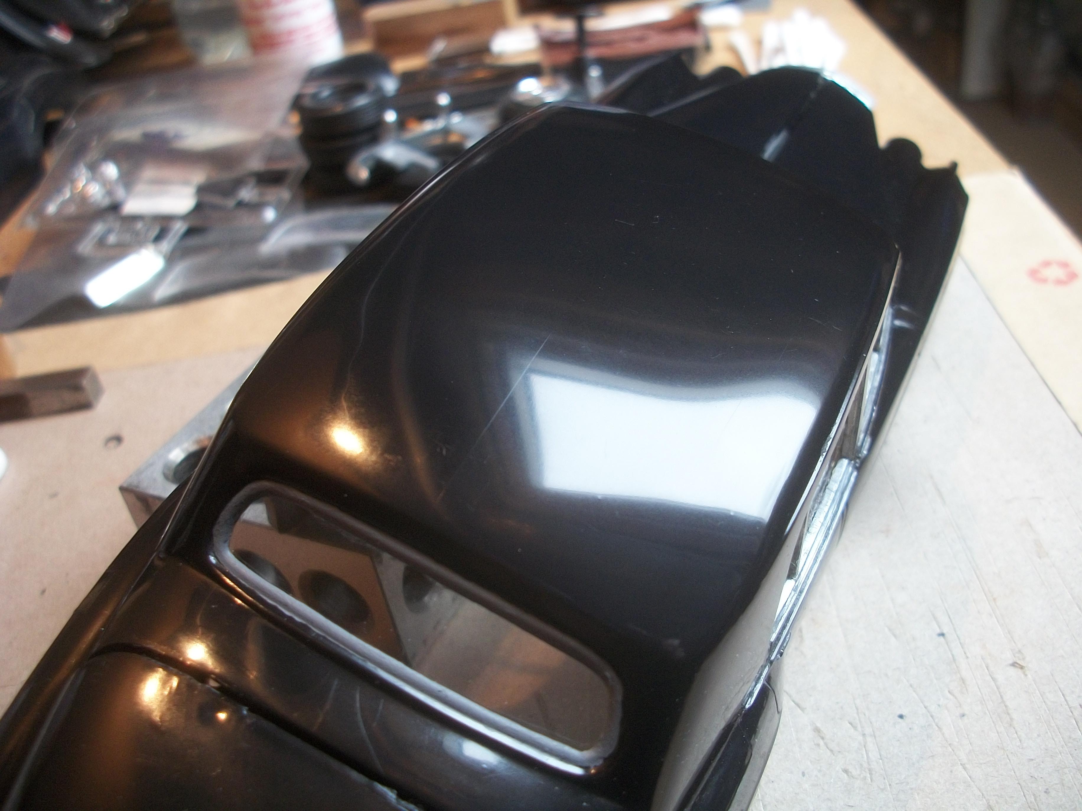
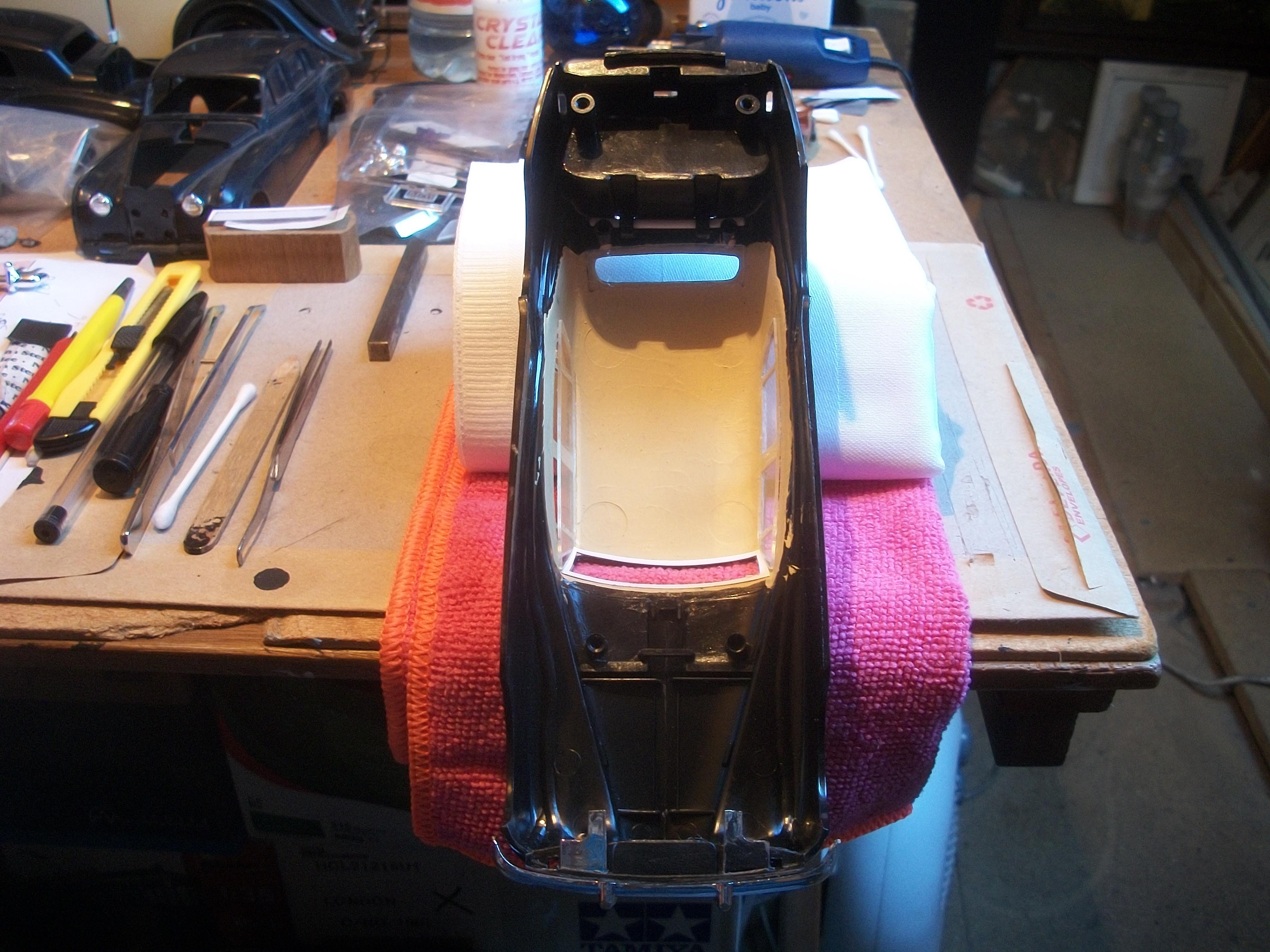
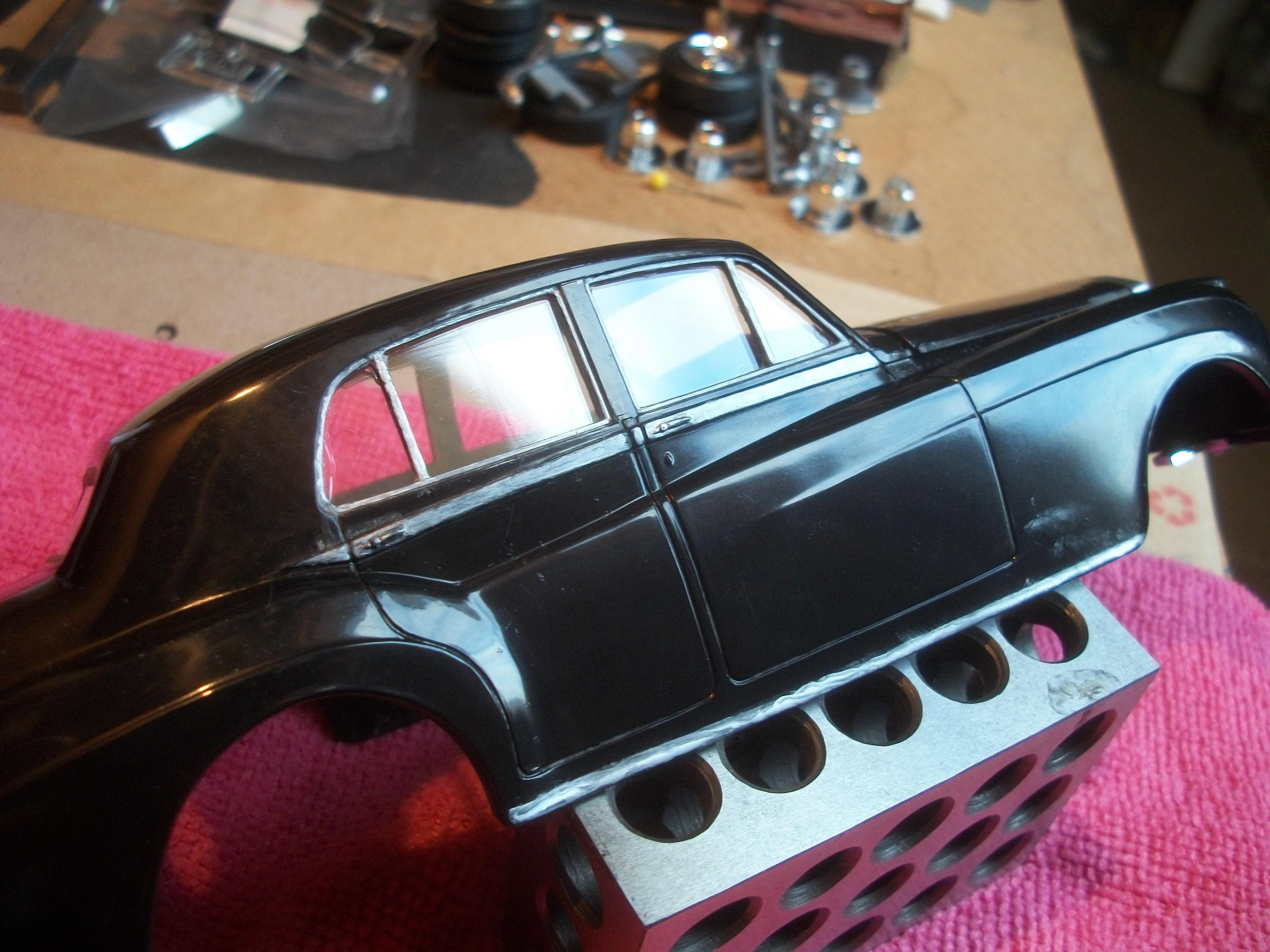
Using the same procedure as with the driver's side of the car, the window glass for the passenger side was glued in place. This has been allowed to set overnight, as before . . . This clears the way to think about how to make the windshield appear to be as realistic as possible. David
-
I like your idea not to reveal what the car will be that you build in 1:16 scale Mark . . . Even better, is to build something from scratch, and just use whatever bits you can find in the stash boxes. Who knows where that might go . . . Good luck with the Ford Fairlane in the meantime. David W.
-
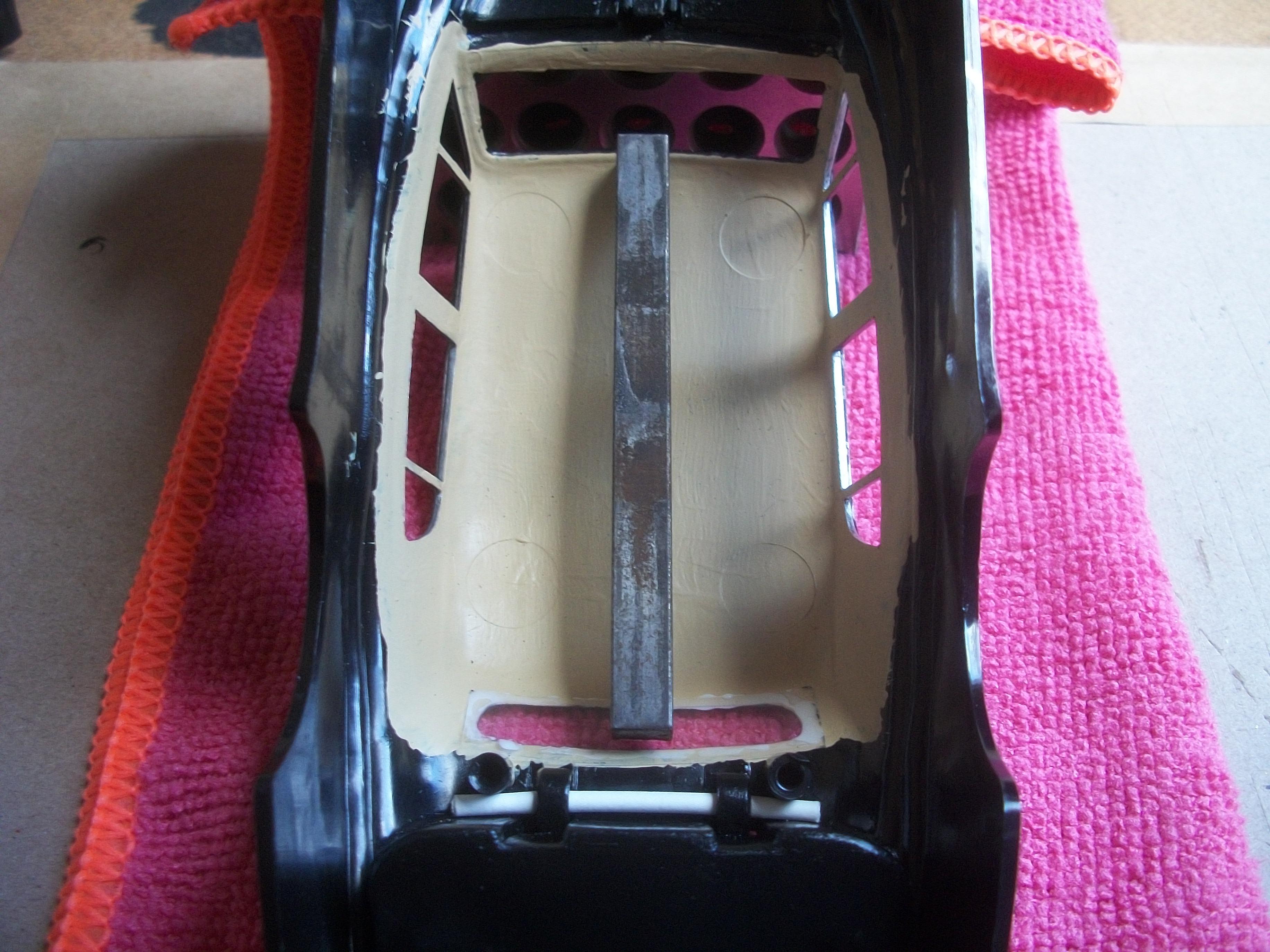
Rolls-Royce No Chemicals, No Paint, No Harmful Glues
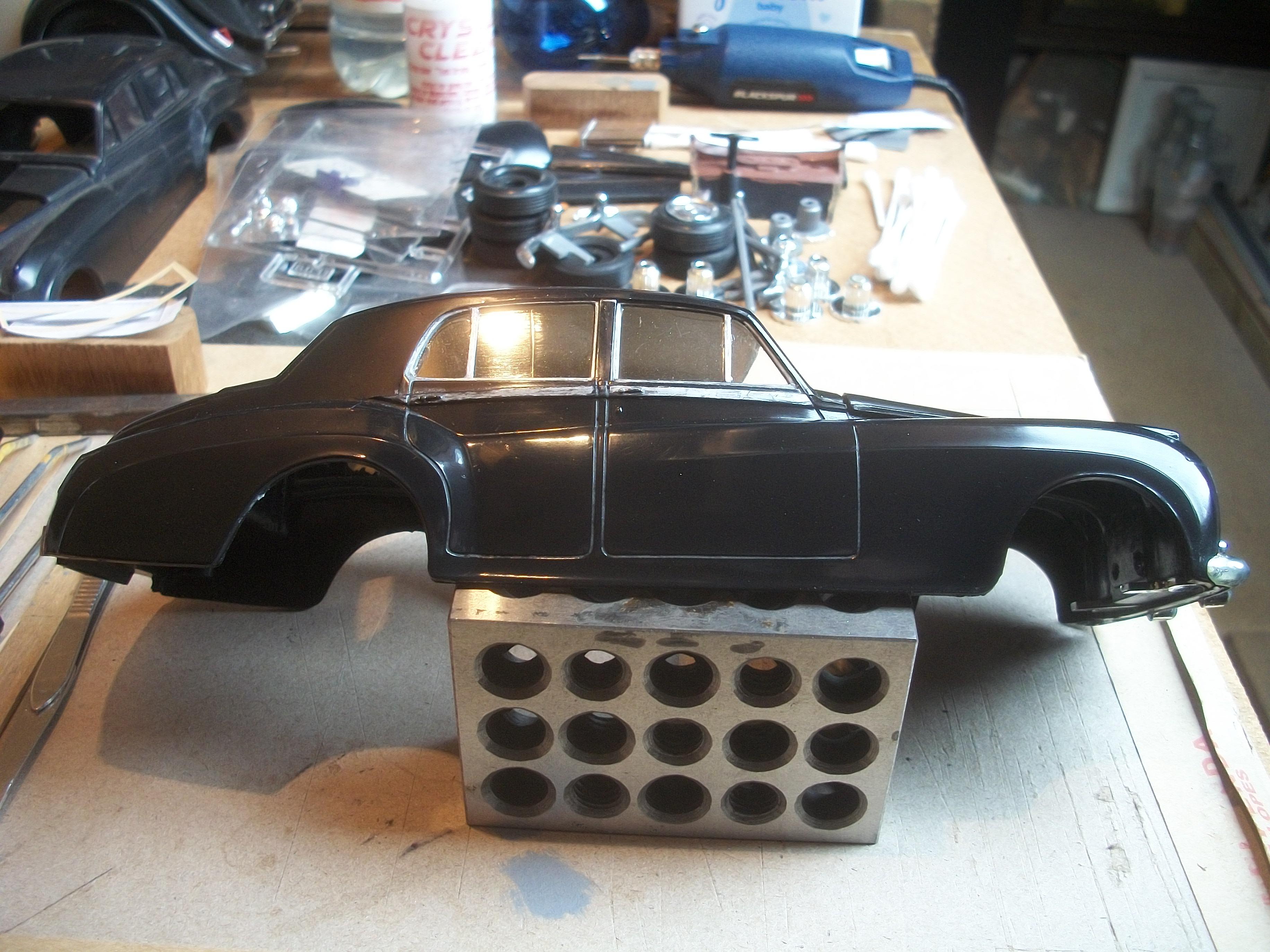
Anglia105E replied to Anglia105E's topic in WIP: Model Cars
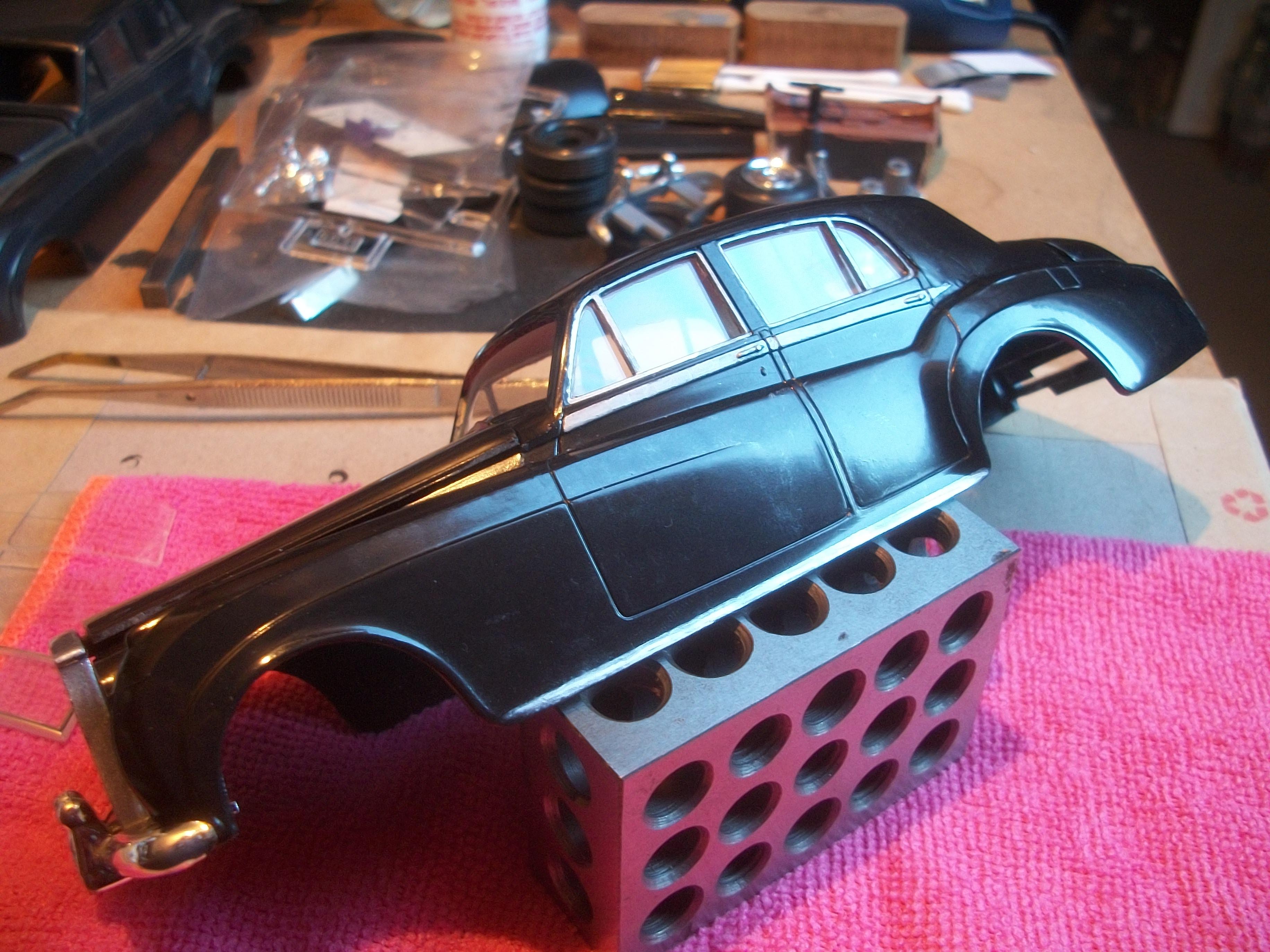
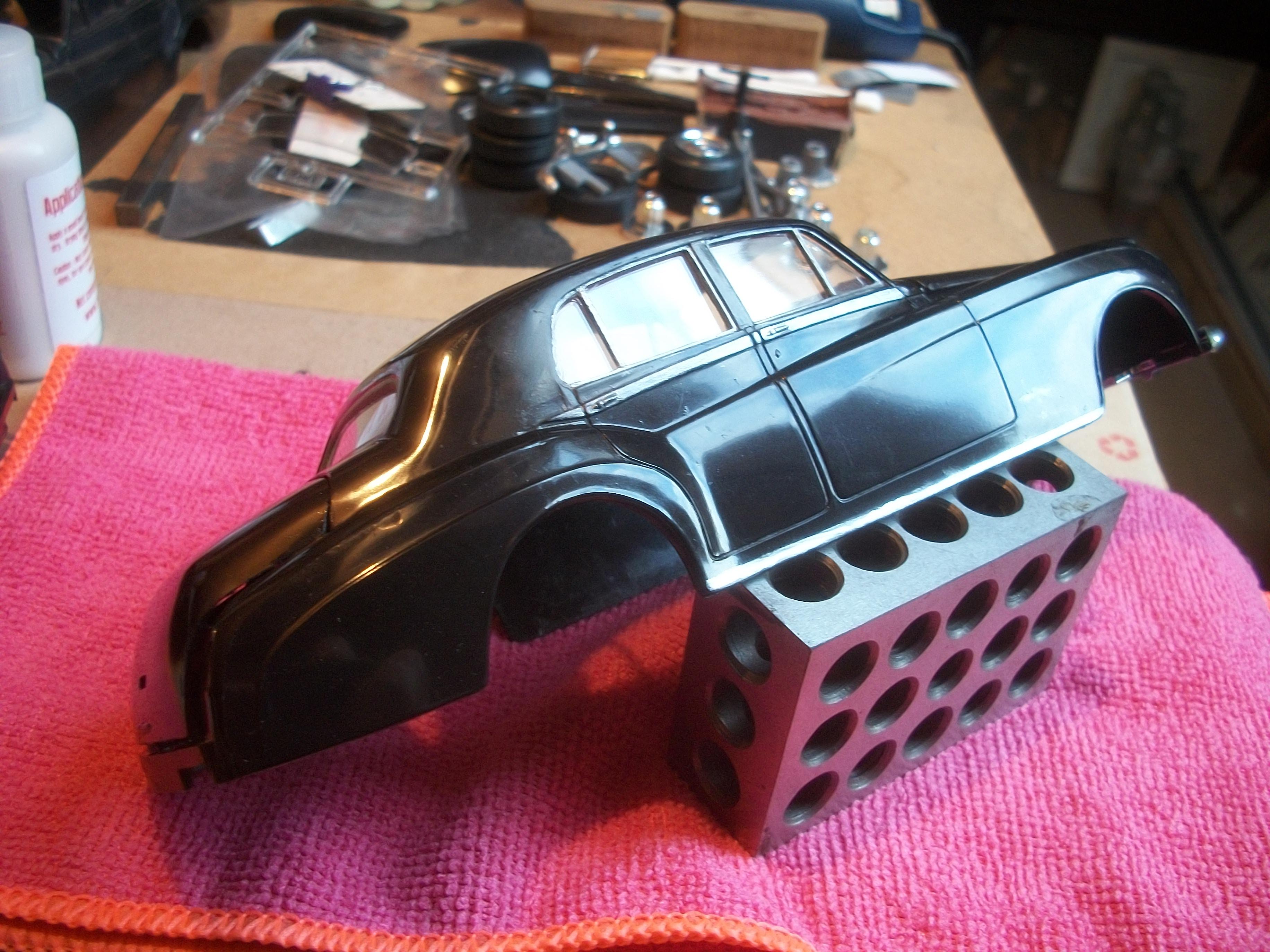
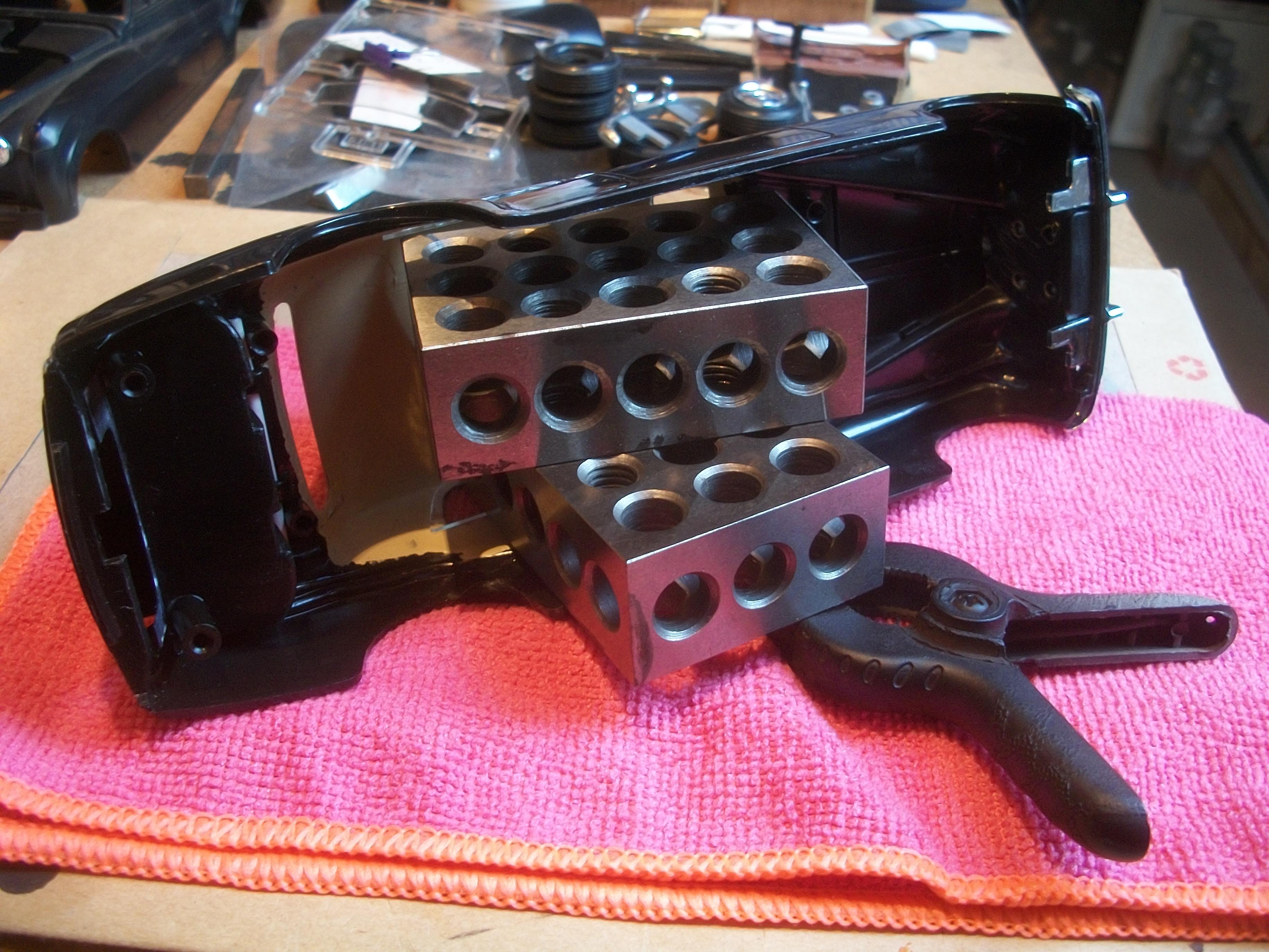
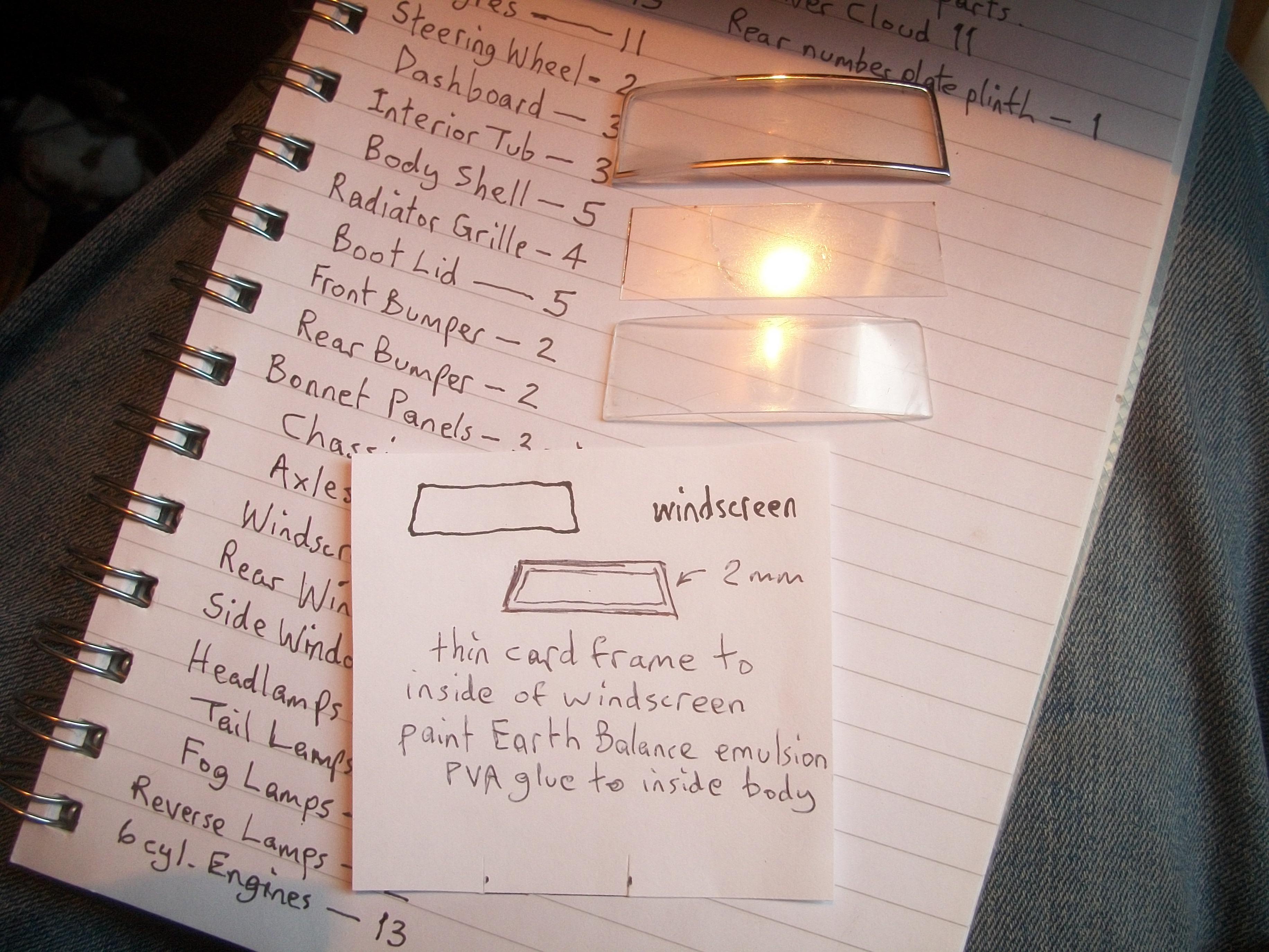
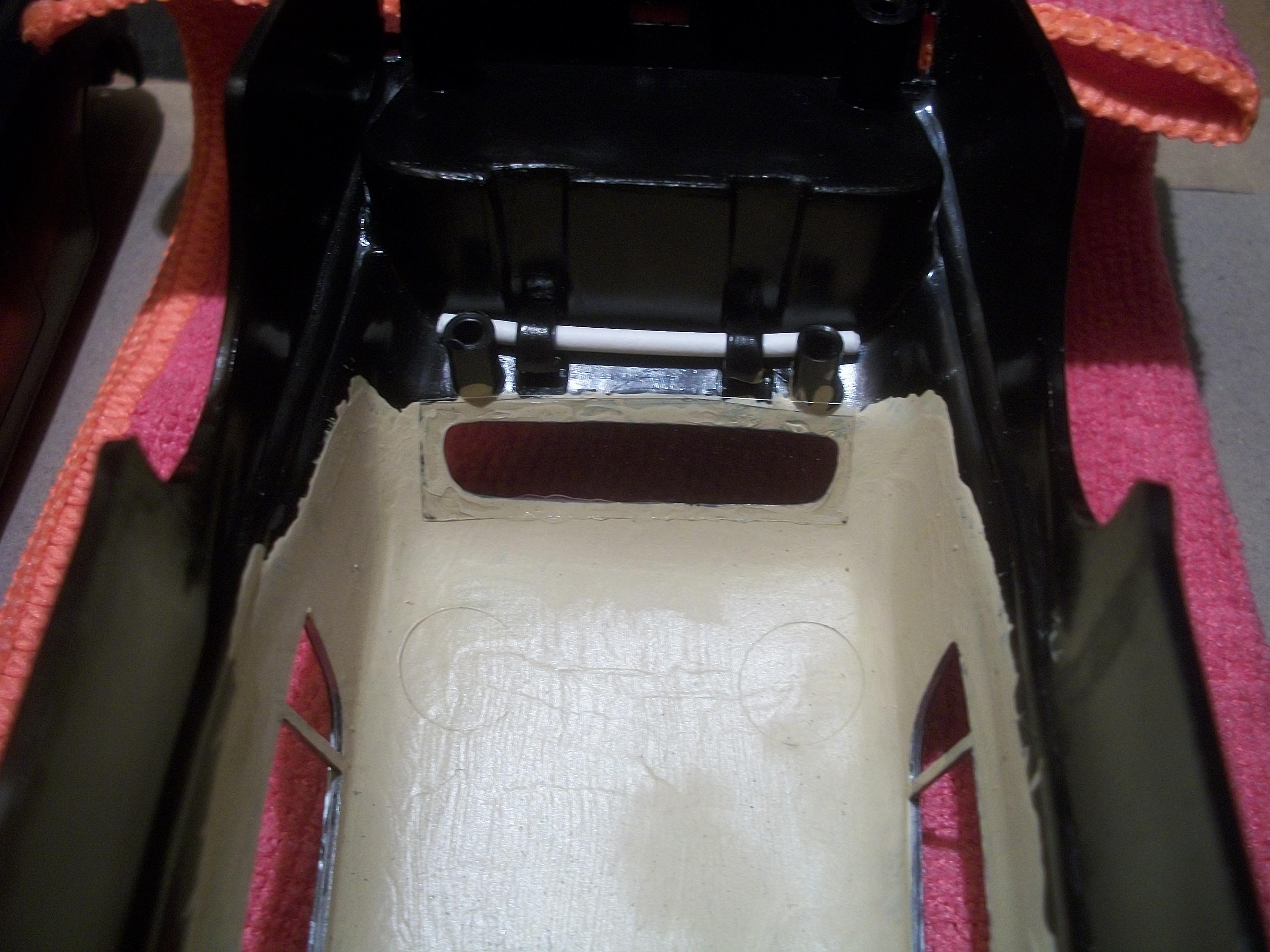
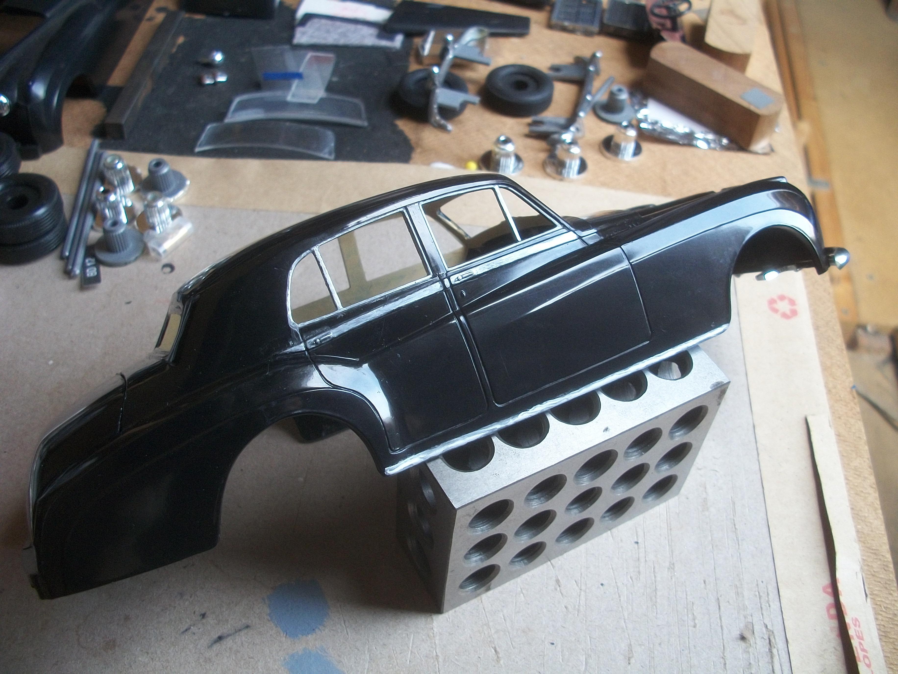
This morning I found that the boot carpet and spare wheel surround panel have set well overnight. Turning my attention to the window glass, I decided to use the kit glass for the side windows. As regards the windshield, an idea came to me last night which involves making a frame out of thin card. The frame can be painted with Earth Balance emulsion, to match the headlining paint, and then glued onto the inside of the body. With the thin clear plastic screen inserted into the windshield aperture, this thin card frame will fit around the screen and will be glued to the surrounding area of the windshield from the inside. About 2 mm in width should be sufficient for the mounting frame. I am hoping this idea is going to work. One of the two side pieces for the window glass has been fitted, using Crystal Clear white glue by Zero Paints . . . This is on the driver's side of the body and I have used two 1-2-3 blocks to weight down the glass for overnight setting. The process will be repeated for the side window glass on the passenger side tomorrow . . . David
-
Rolls-Royce No Chemicals, No Paint, No Harmful Glues
Anglia105E replied to Anglia105E's topic in WIP: Model Cars
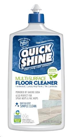
Apparently, the Quick Shine floor cleaner product is available in the UK, but only from Amazon online, so not in high street stores. One of the following photos shows the product as advertised on the Amazon website . . . The rear window glass of the Silver Cloud has turned out nicely, and the exhaust tailpipe has been ' silvered ' with the Sharpie, which flowed generously. This evening I glued in place both the boot carpet and also the spare wheel surround panel, using my friendly PVA glue. David
-
Rolls-Royce No Chemicals, No Paint, No Harmful Glues
Anglia105E replied to Anglia105E's topic in WIP: Model Cars
Thanks Mark, and I have a feeling that Quickshine, or Future as it used to be, might be branded as ' Pledge ' in the UK . . . I shall Google that at some point. None of my model cars are displayed in clear plastic cases, but I would like to get the 1:16 Phantom III in a case one day, and in fact it would be nice to have all of the eight or nine Silver Cloud models in cases also . . . David -
Rolls-Royce No Chemicals, No Paint, No Harmful Glues
Anglia105E replied to Anglia105E's topic in WIP: Model Cars
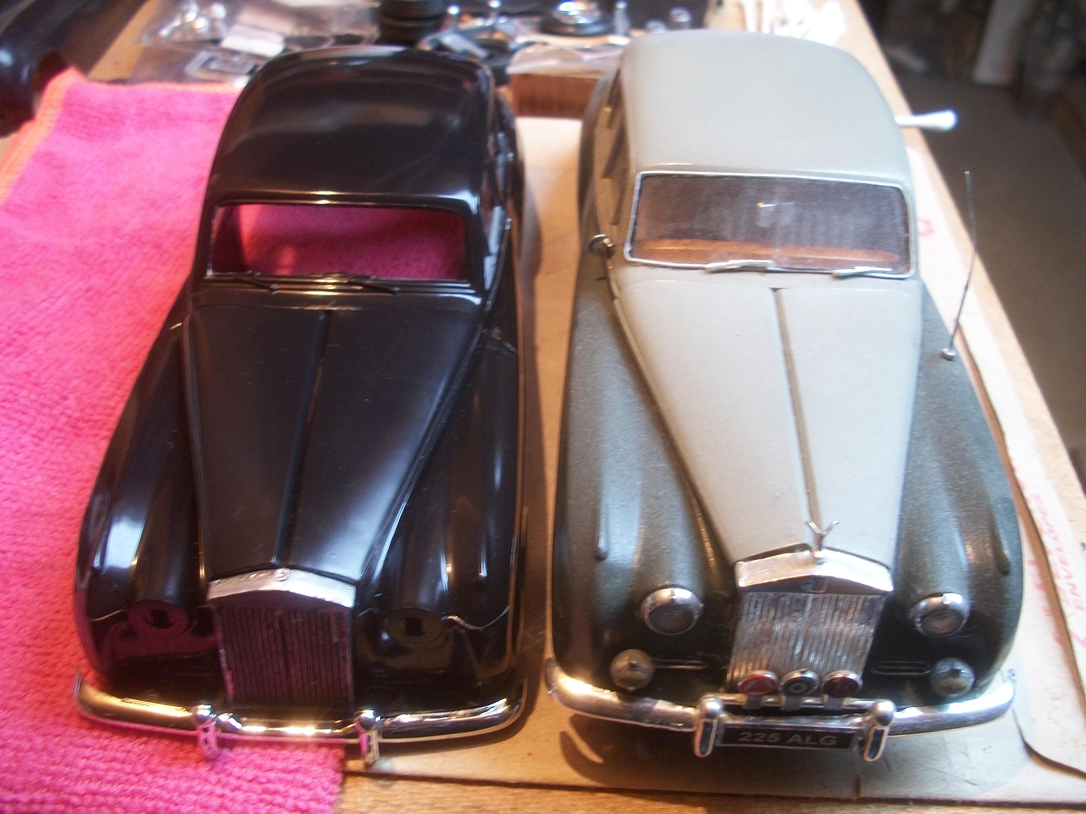
I've seen lots of posts on MCM Forums mentioning Future over the years, and I think if there is a similar product available in the UK then this could be a good idea to give the silver Sharpie some protection once it is applied . . . Having done the rear window glass on the Silver Cloud, there is still the windscreen and the two side window glass parts to deal with. The windscreen is always the tricky one for me, and the realistic appearance of this car relies heavily on getting the windshield absolutely perfect . . . The kit instructions show the glass being fitted from the inside of the body, and the kit glass is way too thick. The alternative method is to fit the windshield glass from the outside of the body, and also to use much thinner clear plastic material, such as cake packaging material for example . . . The most ideal method of locating the windshield glass would be to place it inside the windshield frame aperture, just like the screen would be on the real car, but this is actually very tricky. I might try again with this method if I am feeling clever and confident ! David -
Rolls-Royce No Chemicals, No Paint, No Harmful Glues
Anglia105E replied to Anglia105E's topic in WIP: Model Cars
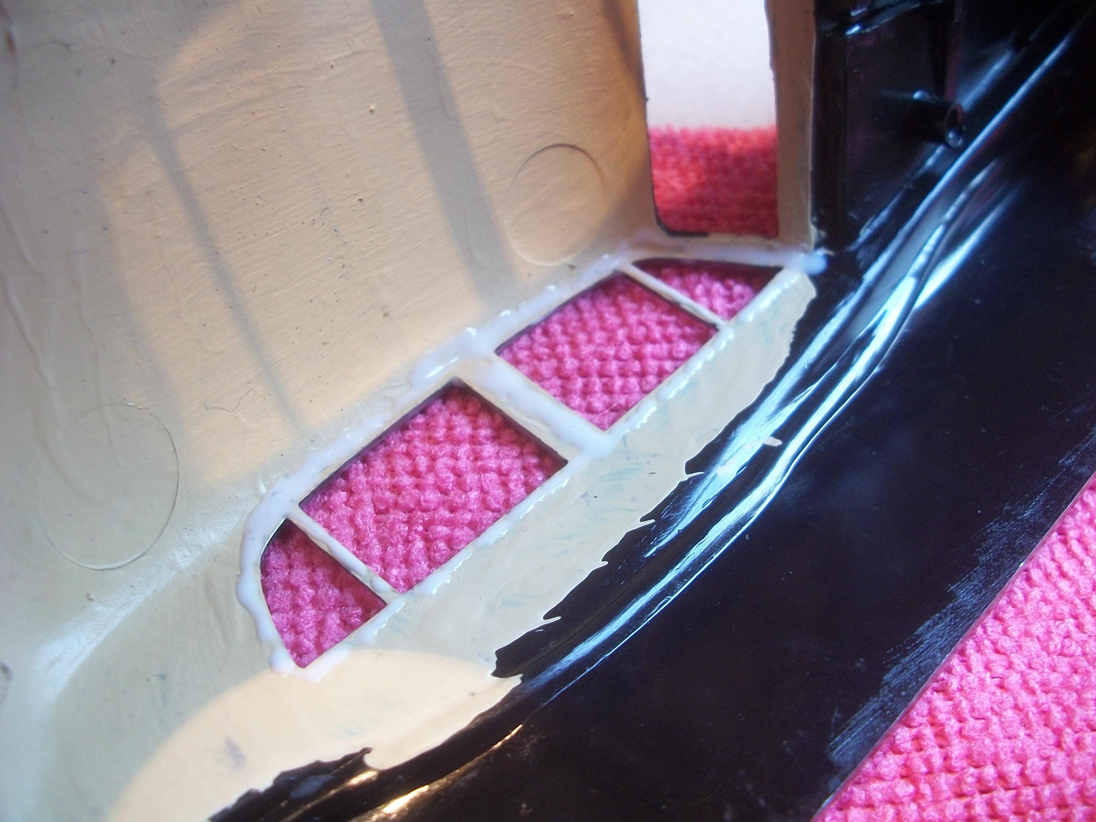
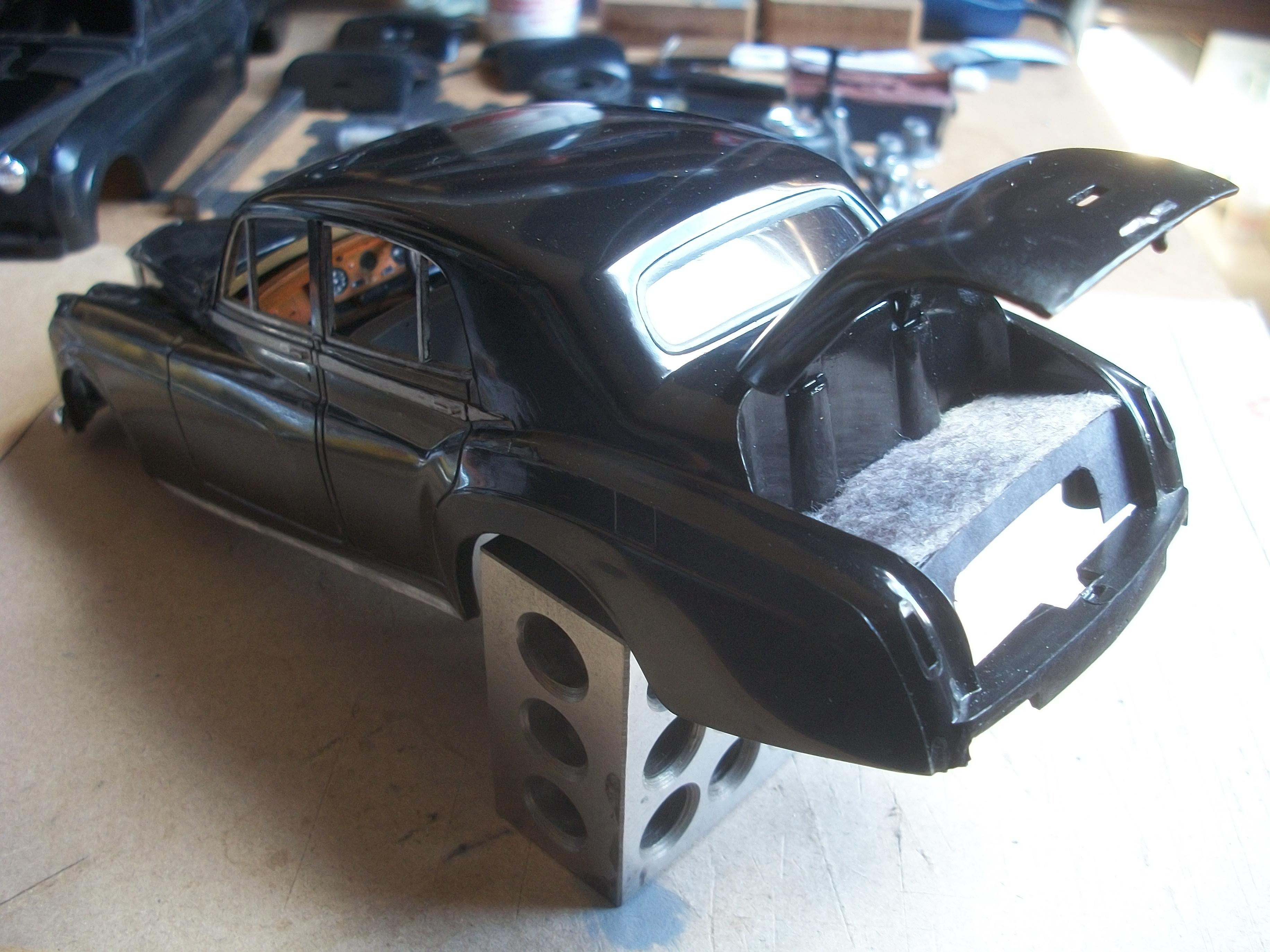
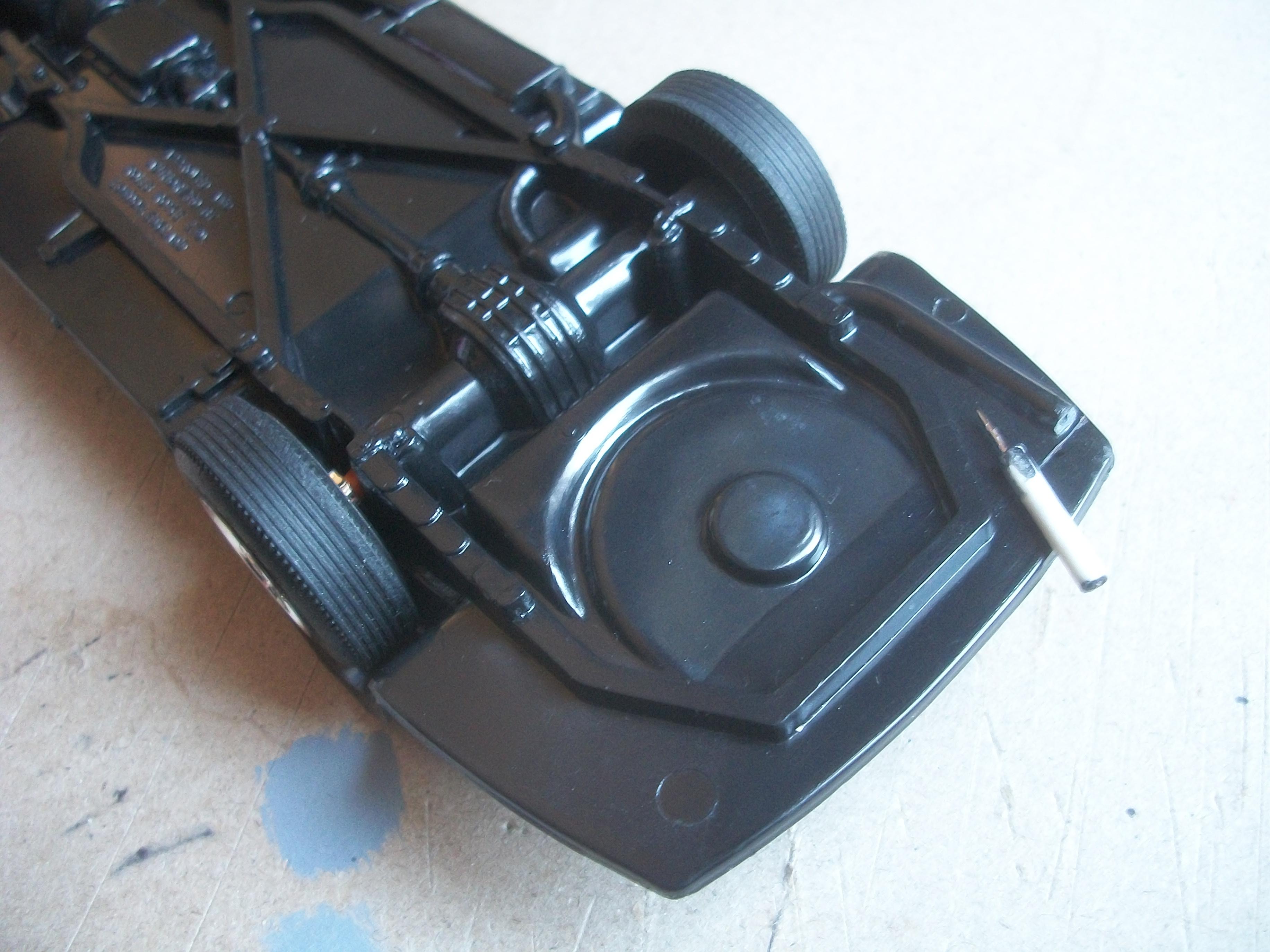
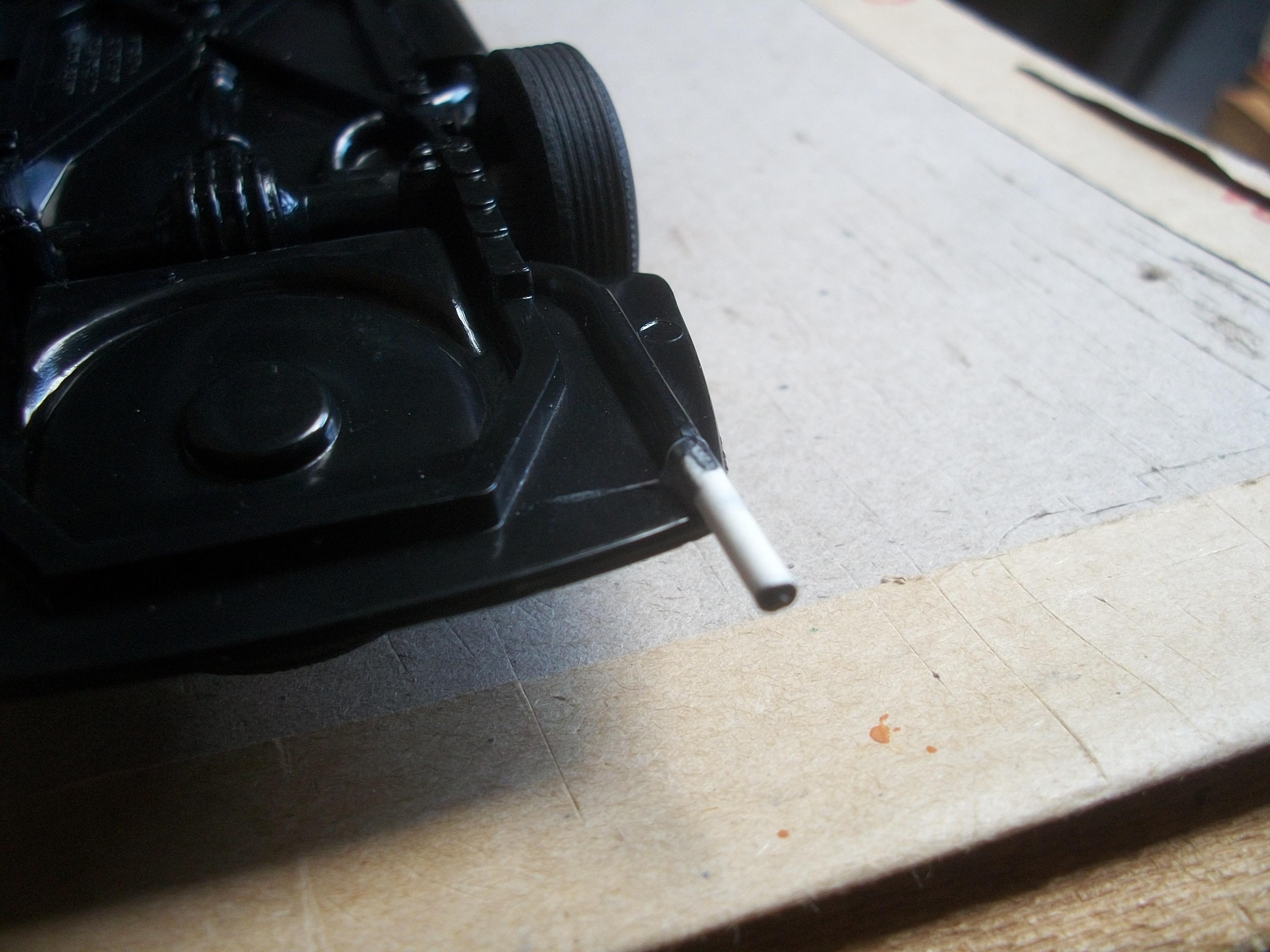
Noticed today that the chrome tailpipe on the exhaust system had fallen off. Fortunately the tailpipe was on my work table ! Also, the BMF had come off the cotton bud stalk, so I shall redo this shortly but using silver Sharpie instead of BMF . . . The tailpipe with its locating pin is glued back in place, using PVA glue. I measured and cut out the front and rear carpets for the interior from grey felt material. These felt carpets are held in place with PVA glue also. Moving on to the rear window glass, I cleaned up the the thin clear plastic film and then used Crystal Clear white glue to hold it in position on the inside of the car. I placed a piece of metal rod on top of the rear window to help keep it in place while the glue sets overnight . . . David
-
Rolls-Royce No Chemicals, No Paint, No Harmful Glues
Anglia105E replied to Anglia105E's topic in WIP: Model Cars
The silver Sharpie chrome ink does have a nice realistic appearance, but the only problem seems to be that the surface of the dried ink is easily smudged and rubbed off. This is even more delicate than the Molotow Liquid Chrome ink in terms of handling . . . I don't think the areas that have been Sharpie'd will ever be safe to handle without smudging. Even worse, is that when I have touched the silver and not realised, then I go and create silver marks on the polished black bodywork with my fingers, which looks terrible. I think these marks will polish off, although not easily. My guess is that the hand sanitiser is keeping the ink from ever drying out completely, although it does a good job of getting the pen to flow from the nib. David W. -
Rolls-Royce No Chemicals, No Paint, No Harmful Glues
Anglia105E replied to Anglia105E's topic in WIP: Model Cars
Thanks a lot John . . . David -
Rolls-Royce No Chemicals, No Paint, No Harmful Glues
Anglia105E replied to Anglia105E's topic in WIP: Model Cars
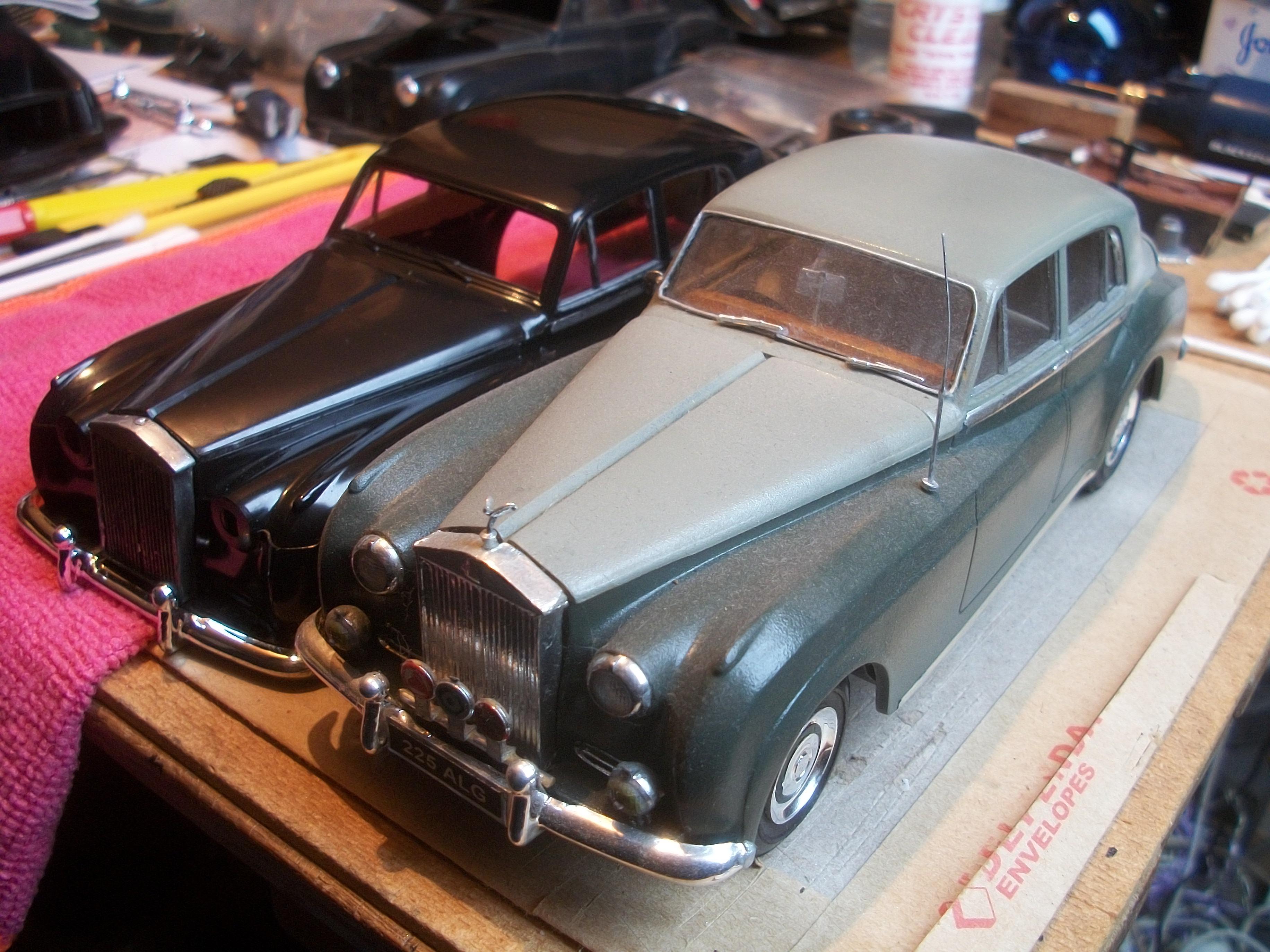
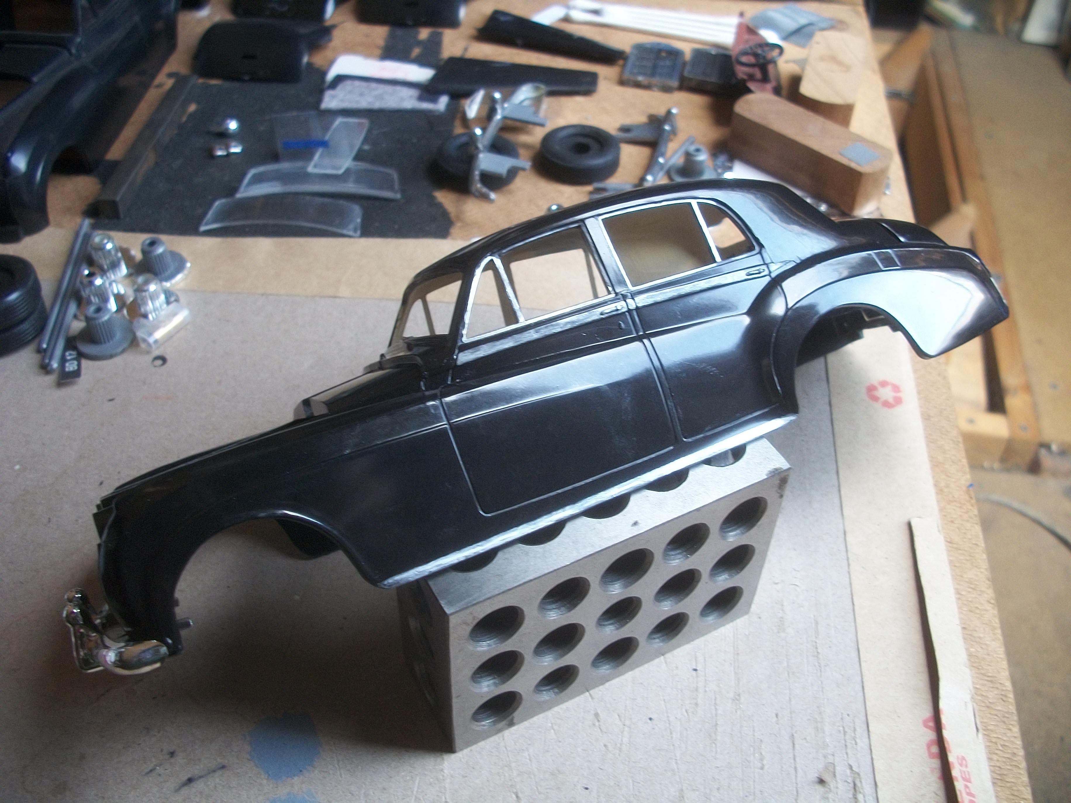
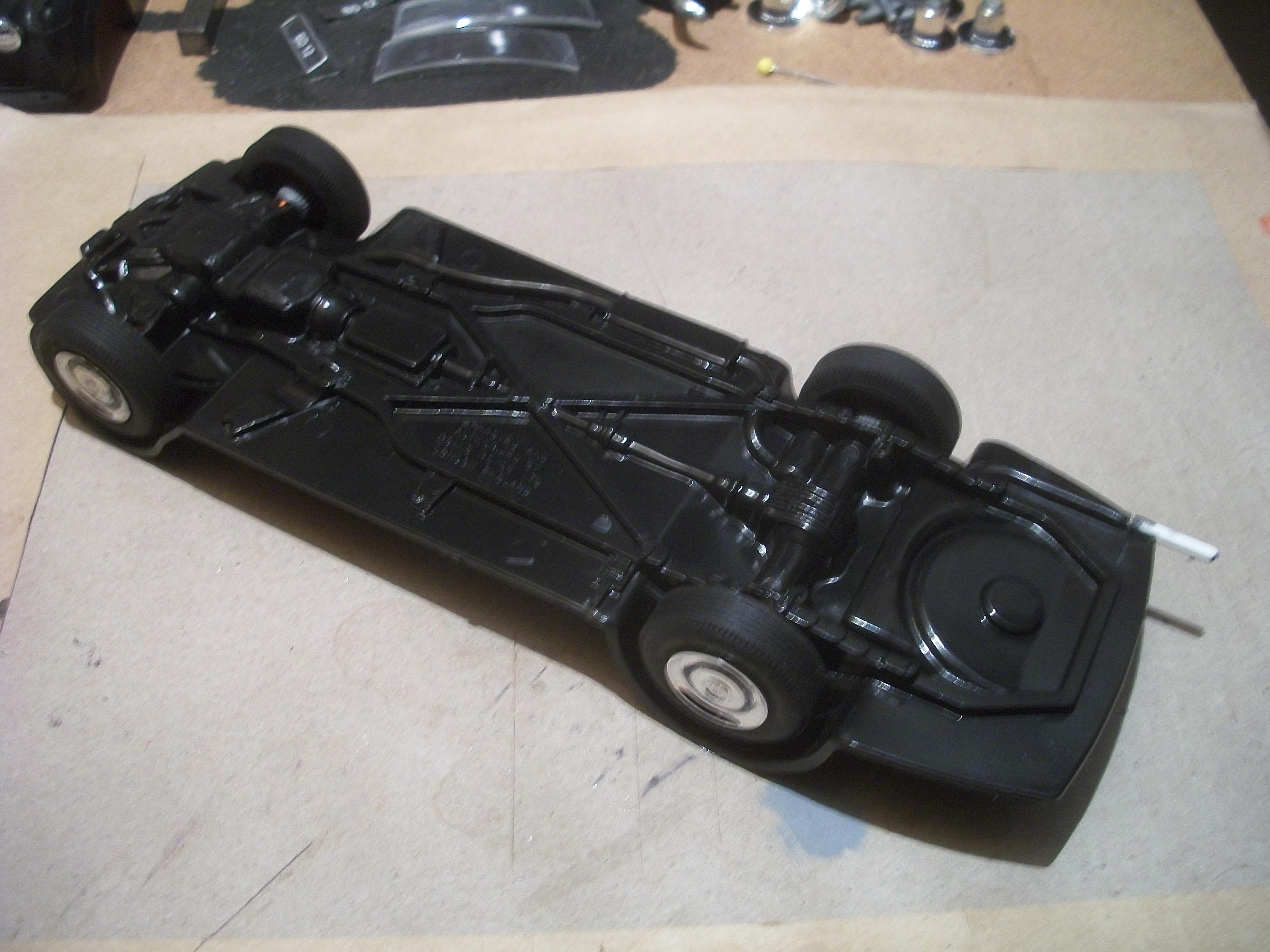
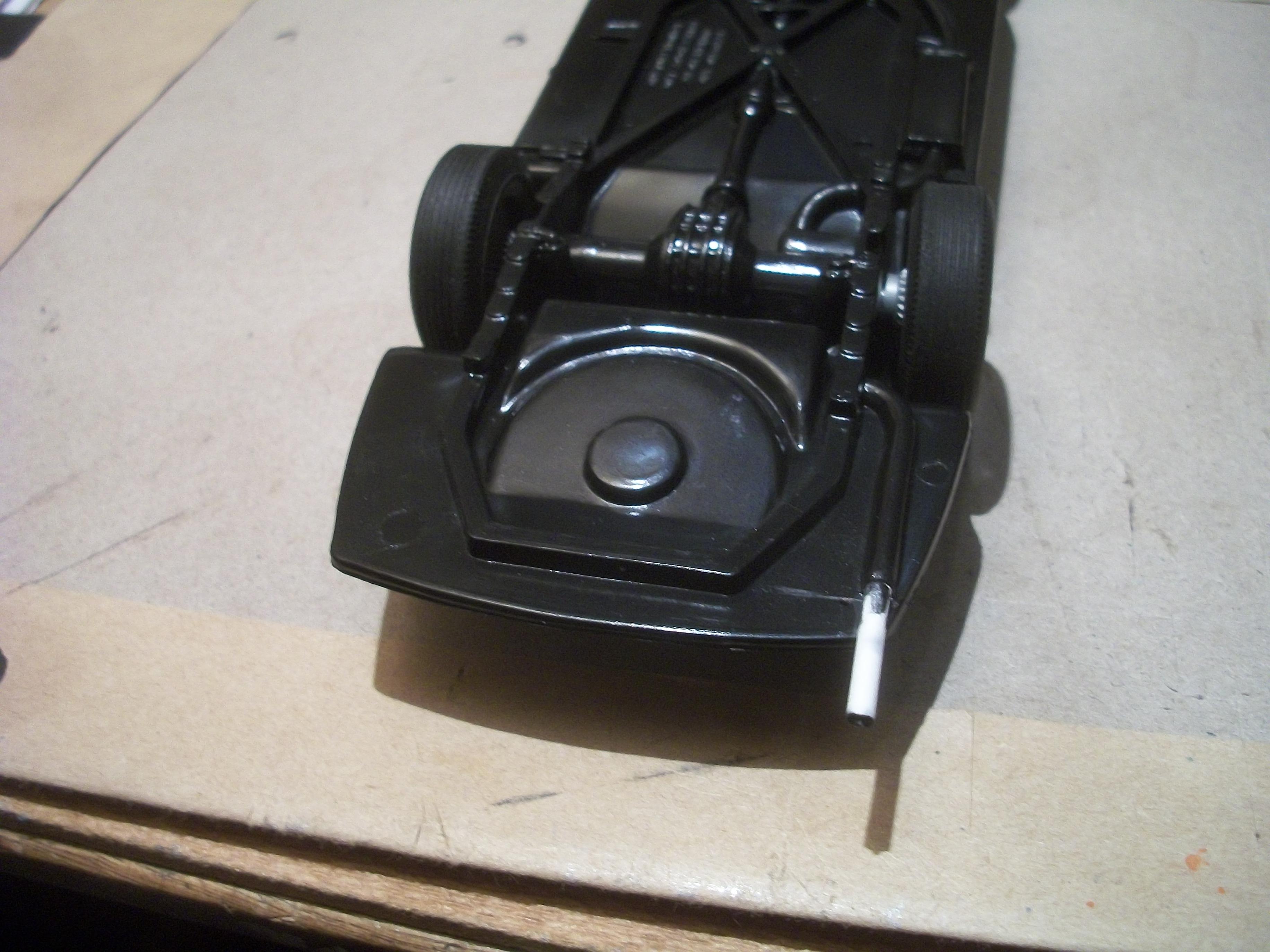
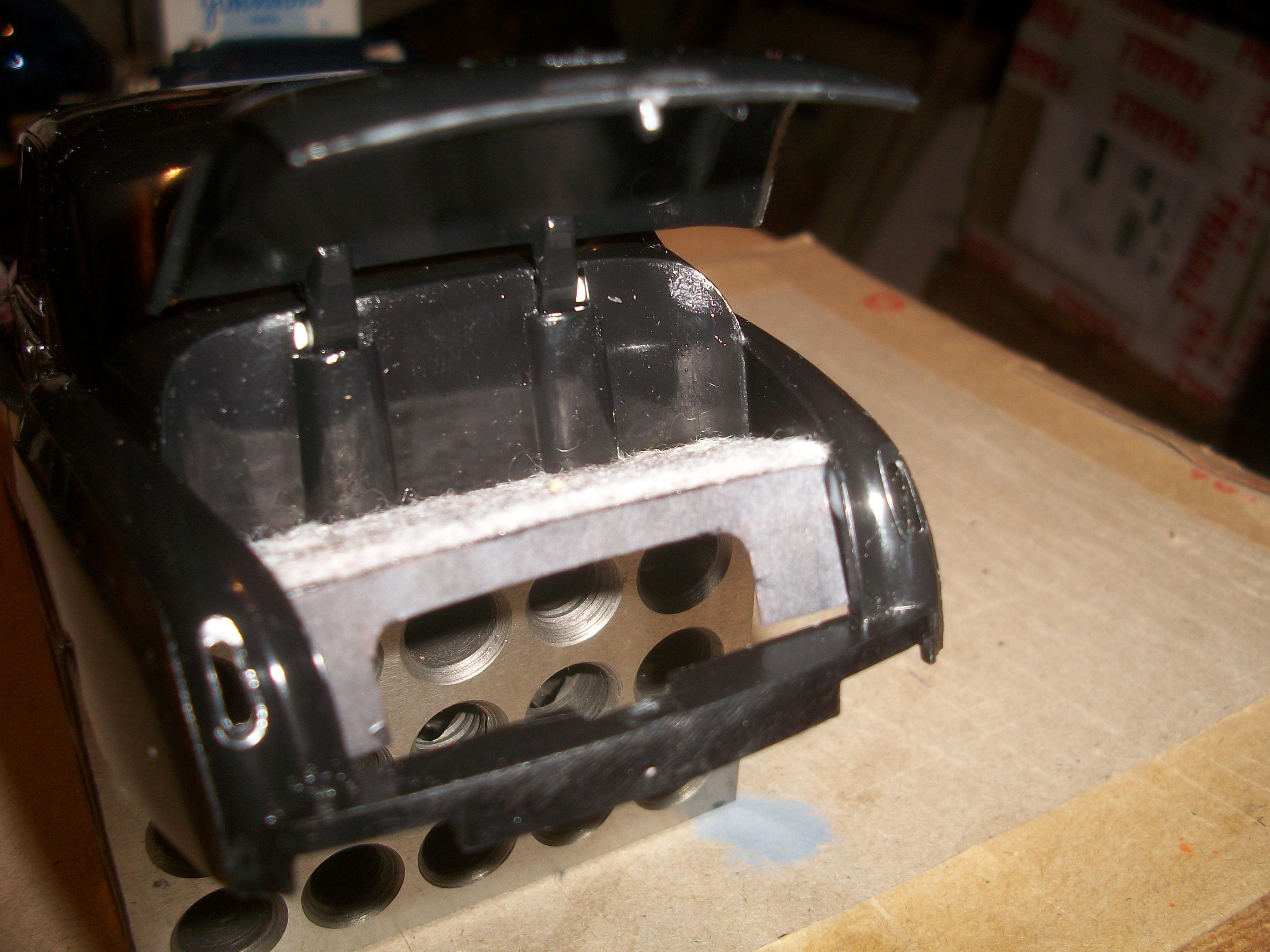
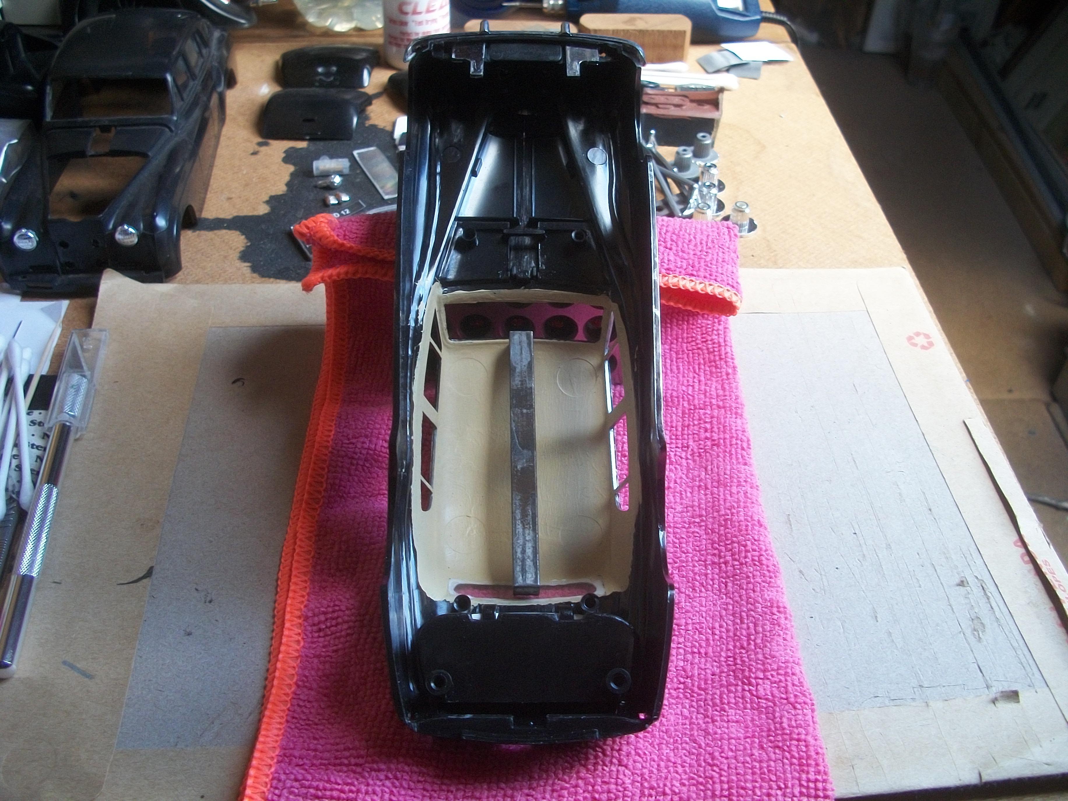
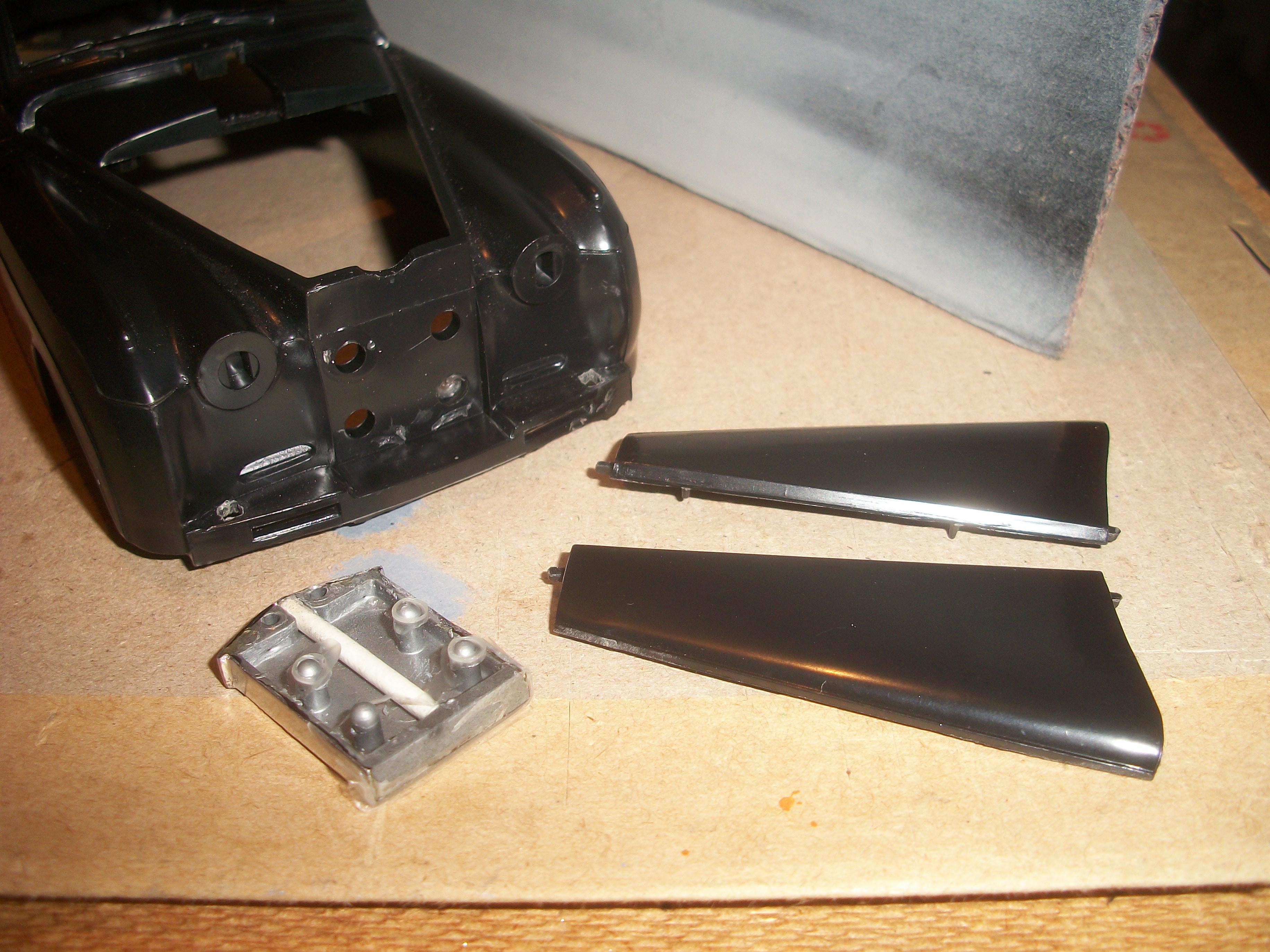
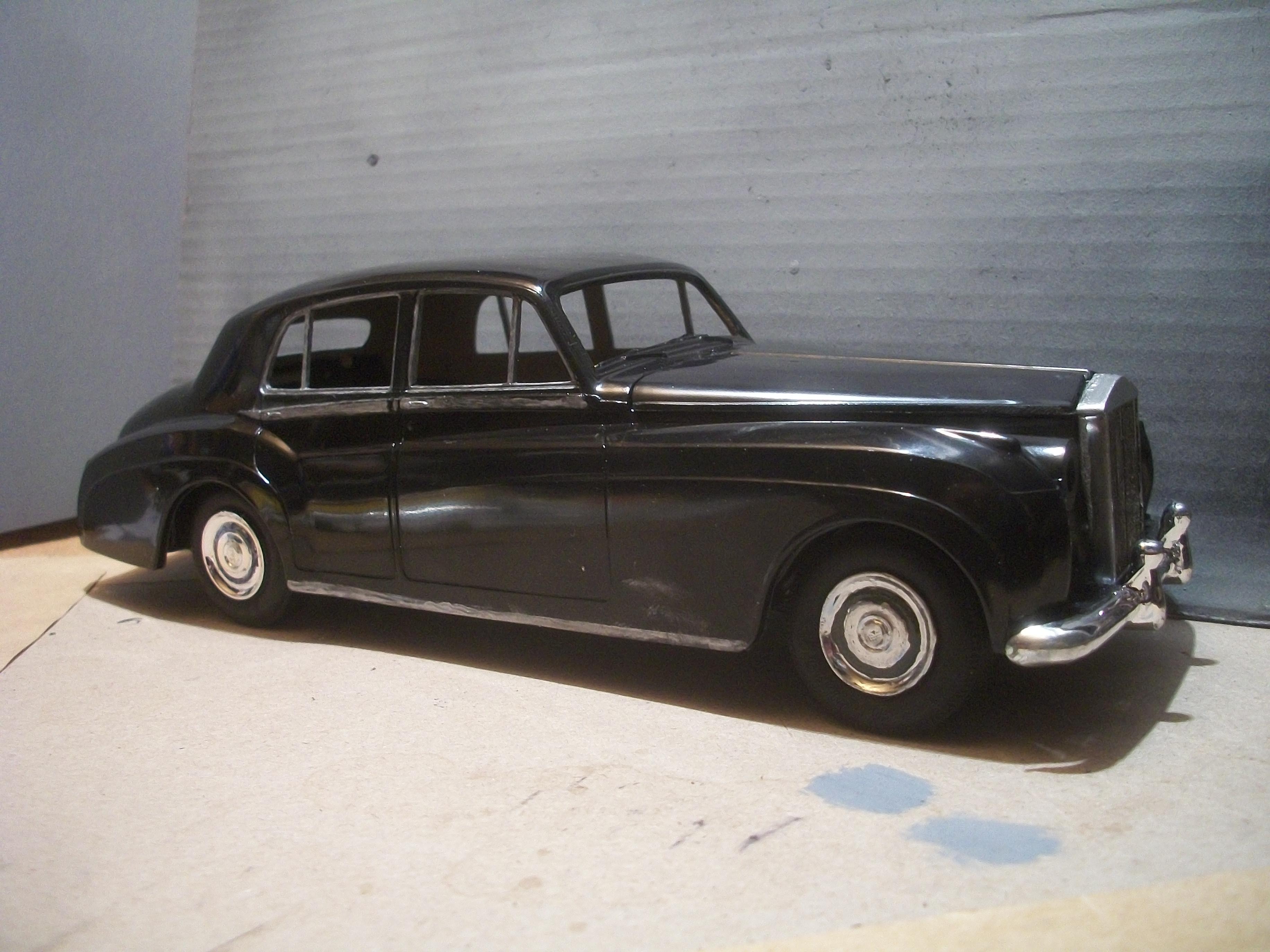
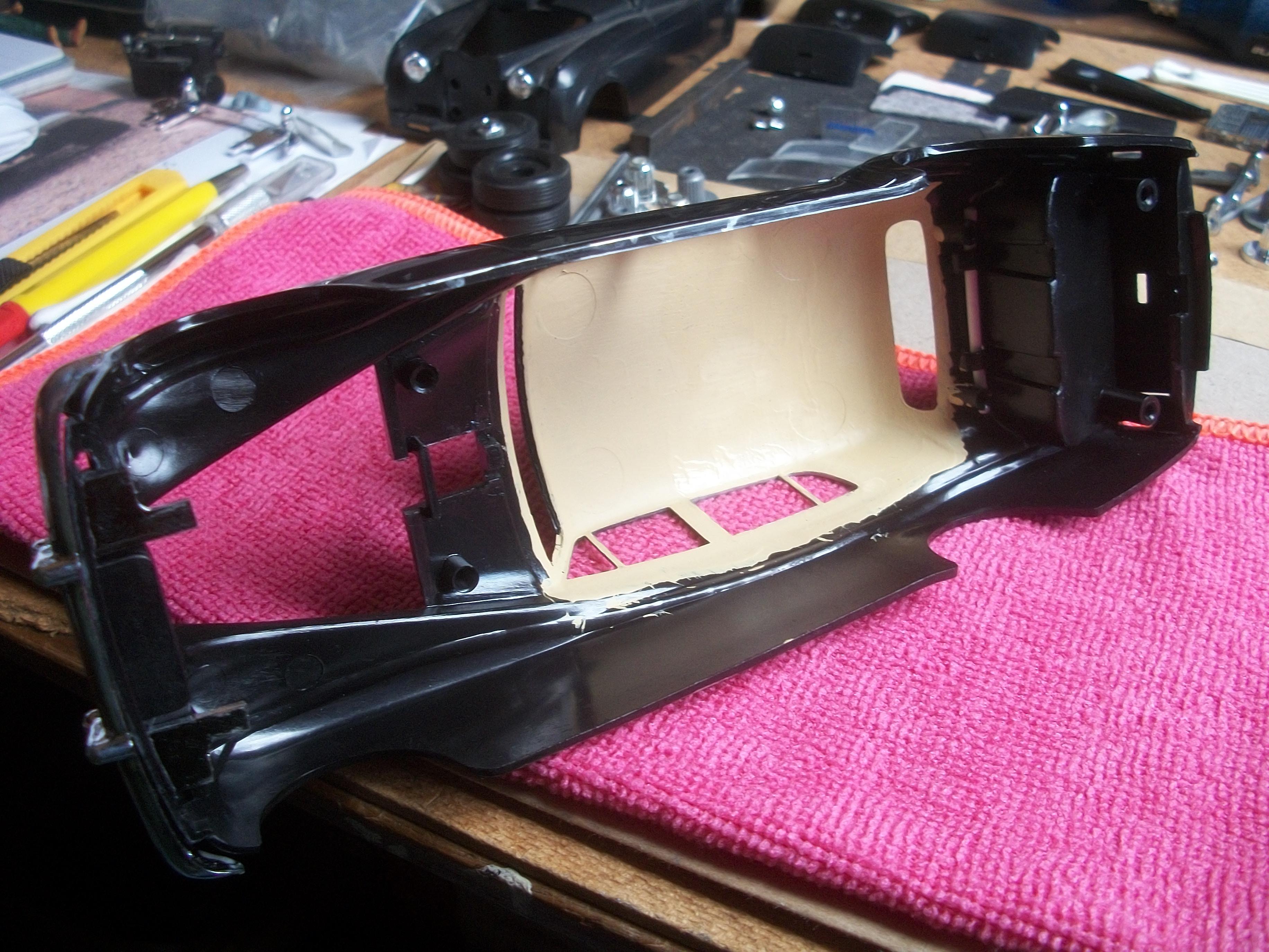
This evening I removed the radiator grille shell and bonnet (hood) panels from the test body and then test fitted them to the actual build body. The radiator grille shell had been mounted using PVA glue, and to my surprise it required quite a bit of force to lever the part away from the front of the body shell. As you can see from the following series of photos, the four recessed holes that are provided to mount the radiator grille shell were not fully drilled through on the body, so I pushed through the plastic with a small round file . . . Once the radiator grille was mounted using a Bostik glue dot, the two bonnet panels were placed into their hinge sockets. These parts seem to be a good fit, with no issues that I can see. The radiator shell serves to hold the bonnet panels in place. I think the Silver Cloud model looks pretty good at this stage as a mock up only . . . David
-
Rolls-Royce No Chemicals, No Paint, No Harmful Glues
Anglia105E replied to Anglia105E's topic in WIP: Model Cars
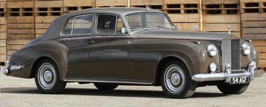
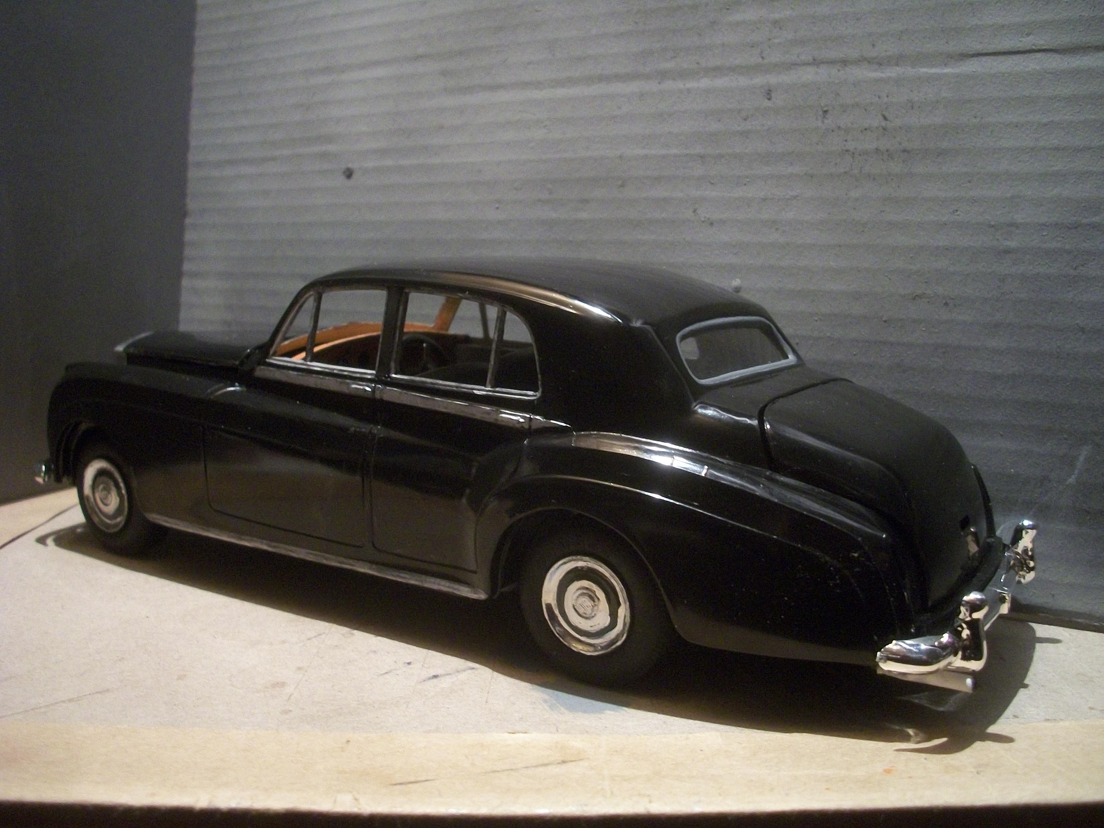
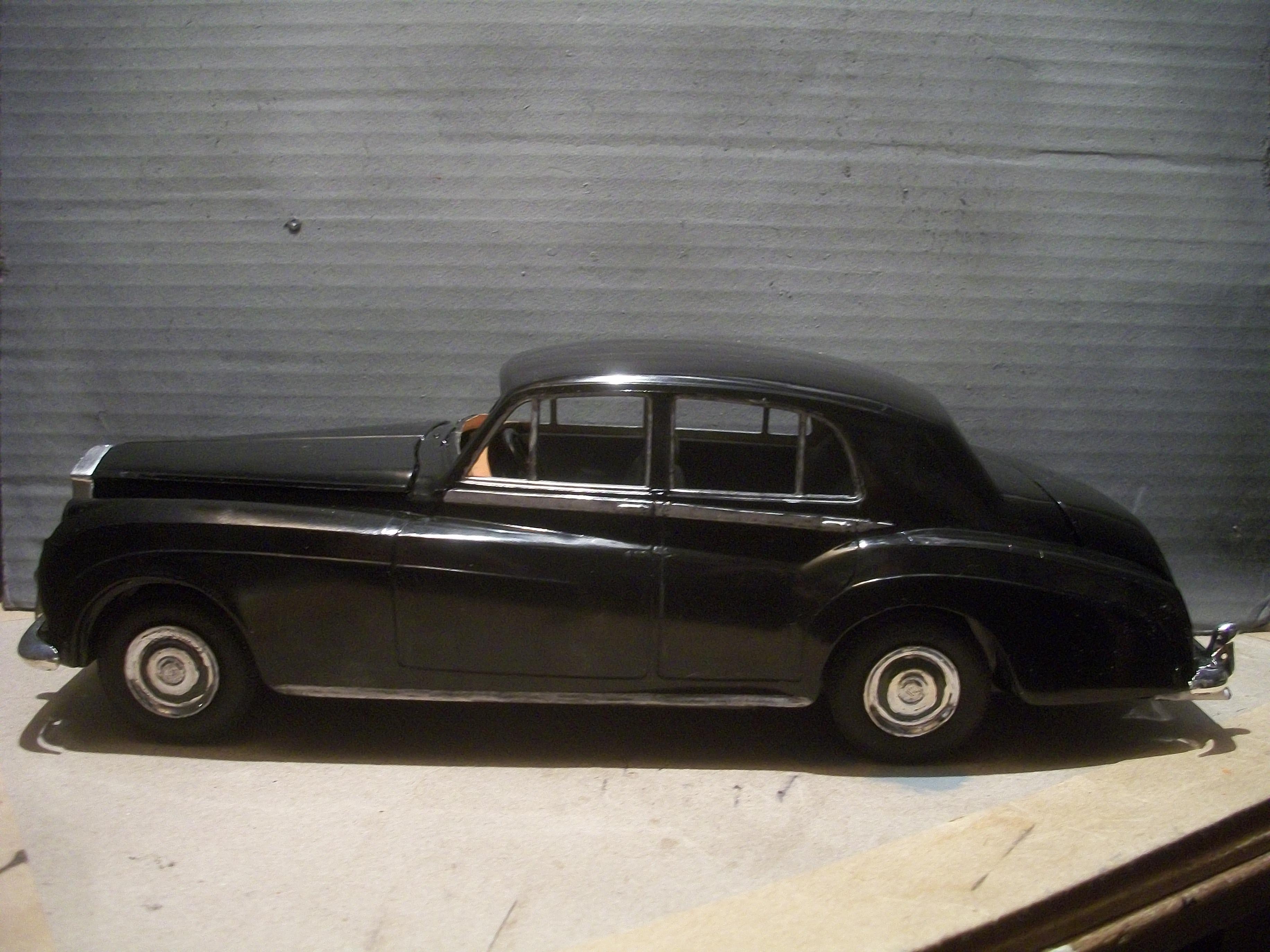
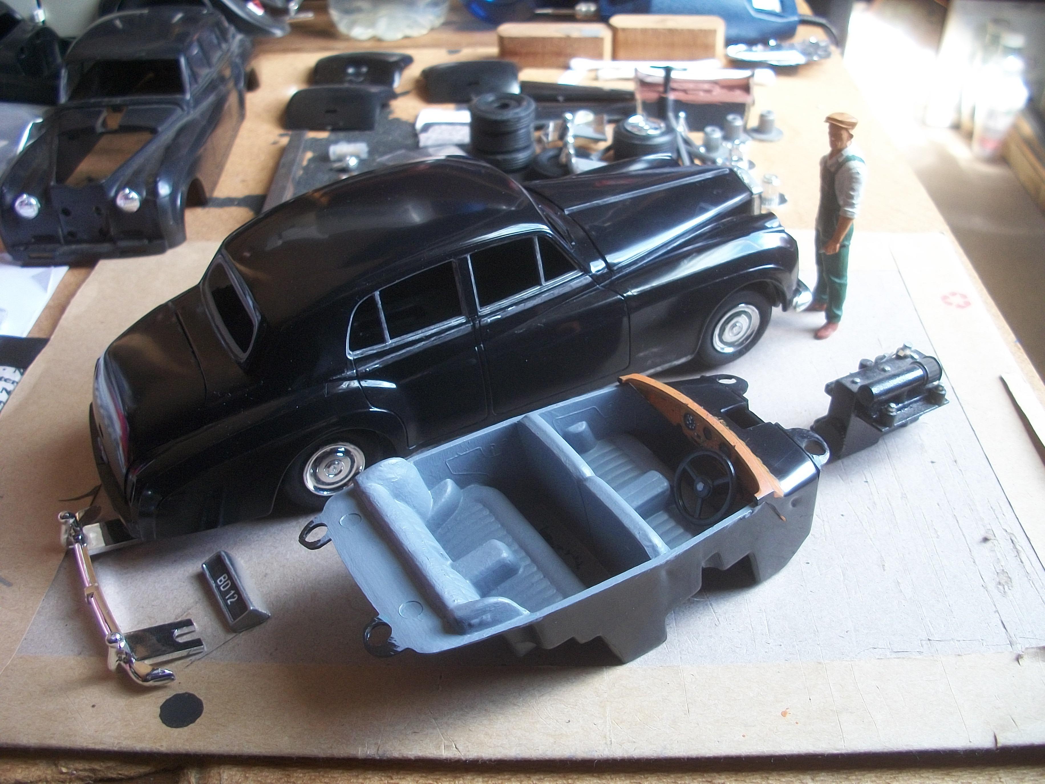
Okay here are the details Mark . . . The actual car is a 1957 Rolls-Royce Silver Cloud that was supplied new in 1957 to Bernard Dixon, by the London dealership Jack Barclay, and the registration number was BD 12, with the chassis number SDD54 . . . The car was finished in black, the engine was a 4.9 litre straight six (299 cubic inches), and this car remained in the ownership of Bernard Dixon from 1957 to 1959. The car appeared in a famous film " The Fast Lady " in 1962, by which time the registration plate had been changed to 200 DYO following change of ownership. This Silver Cloud later found a new owner, who changed the paint scheme to black over gold two-tone and fitted a Webasto sunroof that covered the whole roof area . . . As regards my model version of this car, this one is a 1:24 scale kit that uses parts from both the Minicraft version of the kit and also the Revell version, as well as the Entex kit. The kit was originally produced by Hubley in the US, and then Entex, Academy and Masterkit of Brazil . . . It was Hubley who produced the first promo version of the Silver Cloud II in 1959. David -
You mentioned your next build, and I find that 1:16 scale is a very nice scale in which to work. Having built my Dad's Ford Cortina MK I as produced by FROG in 1:16 scale, it was a real pleasure to go on to build the Gunze Sangyo Rolls-Royce Phantom III, also in 1:16 scale. The Ford Cortina was advertised on Ebay as a two door car, and the box art by FROG also shows a two door car. What I needed was a 4 door car that was my Dad's, and I saw an article online which stated that the kit inside the box is actually a 4 door version . . . This turned out to be true, much to my delight. The 1:16 scale model cars do take up a lot of space once they are assembled, especially the Rolls-Royce which is 13 inches in length, but I don't mind as these large models display so well. Of course, I would love to build models in 1:12 scale and even 1:8 scale ( Pocher ), but I cannot afford to purchase such kits. David
-
Rolls-Royce No Chemicals, No Paint, No Harmful Glues
Anglia105E replied to Anglia105E's topic in WIP: Model Cars
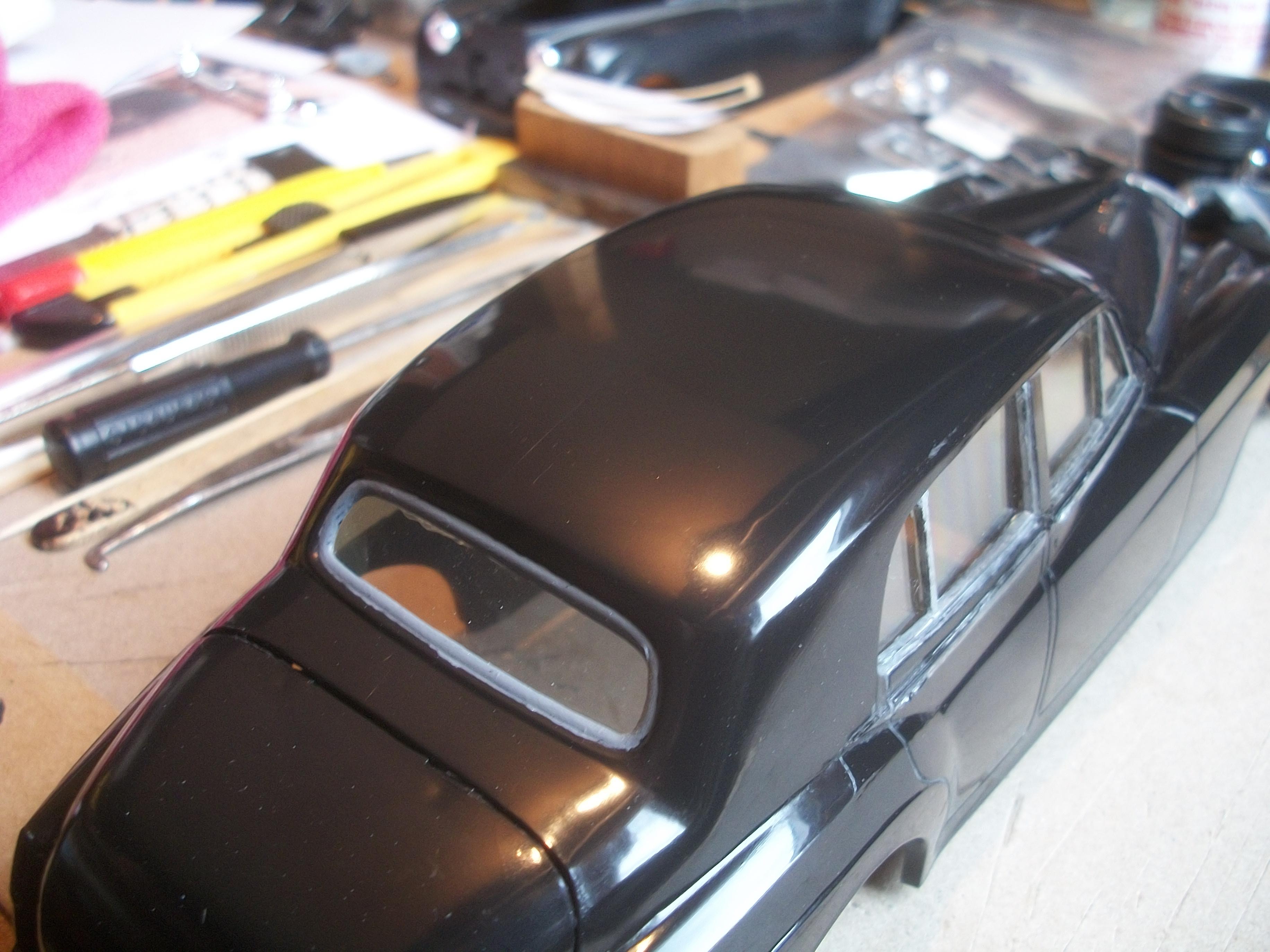
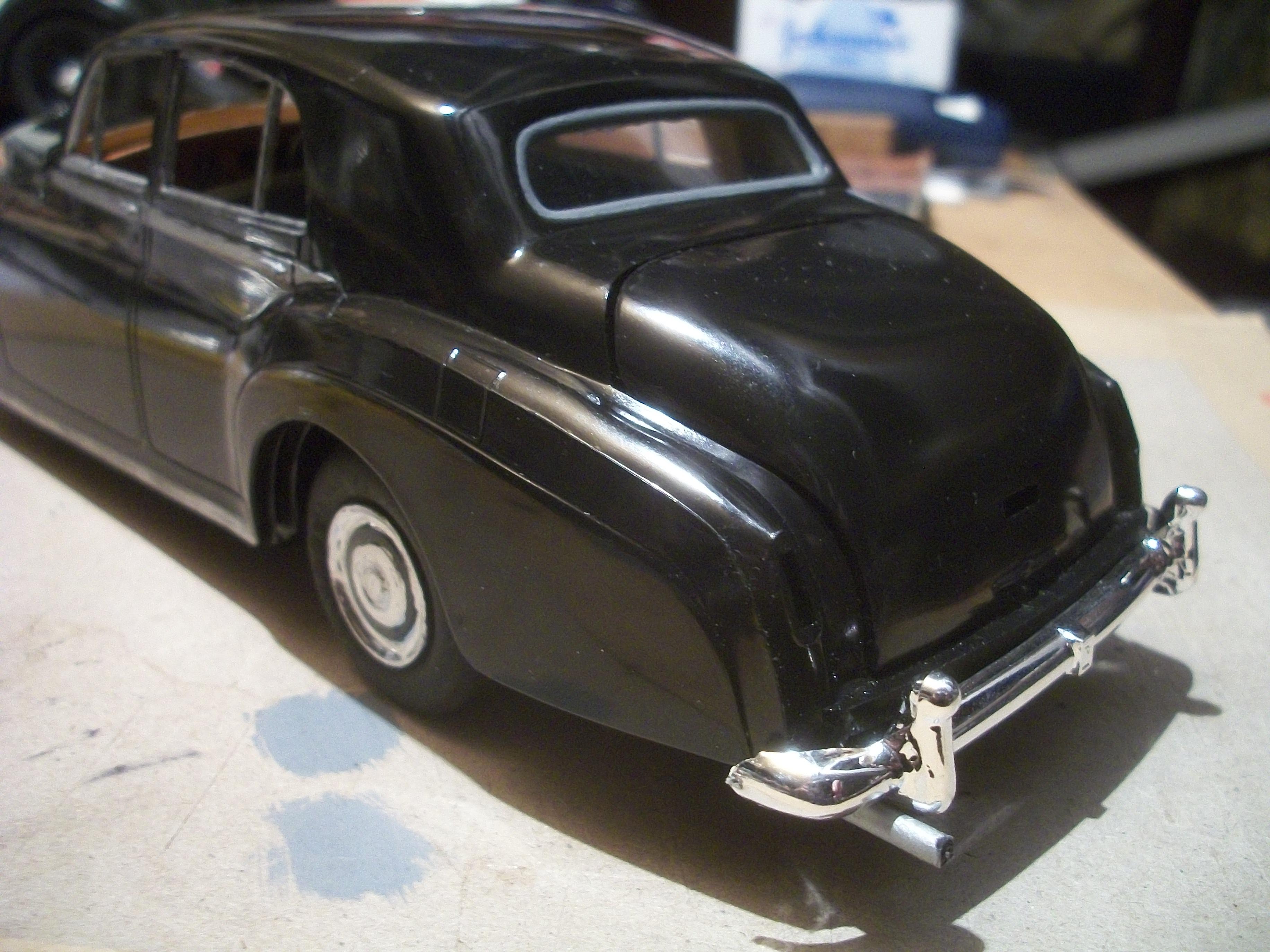
The sill mouldings have turned out quite nicely, and I spotted a grey patch on the beige headlining on the underside of the roof, so this was overpainted with some ' Earth Balance ' emulsion . . . I also used some grey emulsion paint on the rear window seal. Over the years I have seen model builders who have painted the rear window surround on the outside with chrome, but this is not correct and it should be a grey rubber seal. David
-
I wrongly assumed that both of the photos that I sent you were of real 1:1 cars. However, I think you are correct in saying that the second photo is a scale model car, but how can you tell that it shows a 1:64 scale model? David
-
Rolls-Royce No Chemicals, No Paint, No Harmful Glues
Anglia105E replied to Anglia105E's topic in WIP: Model Cars
Always good to make progress Steve . . . I was pleasantly surprised to see the hand sanitizer work so well, especially when 100% Isopropyl Alcohol did not seem to work in a previous attempt . . . It does look like the silver finish of this Sharpie is easily rubbed off, so I must handle the body with care when carrying out other tasks, such as polishing for example. Of course, with hindsight, I should have polished first and then done the silvering / chroming afterwards. David