Anglia105E
-
Posts
3,486 -
Joined
-
Last visited
Content Type
Profiles
Forums
Events
Gallery
Everything posted by Anglia105E
-
Rolls-Royce No Chemicals, No Paint, No Harmful Glues
Anglia105E replied to Anglia105E's topic in WIP: Model Cars
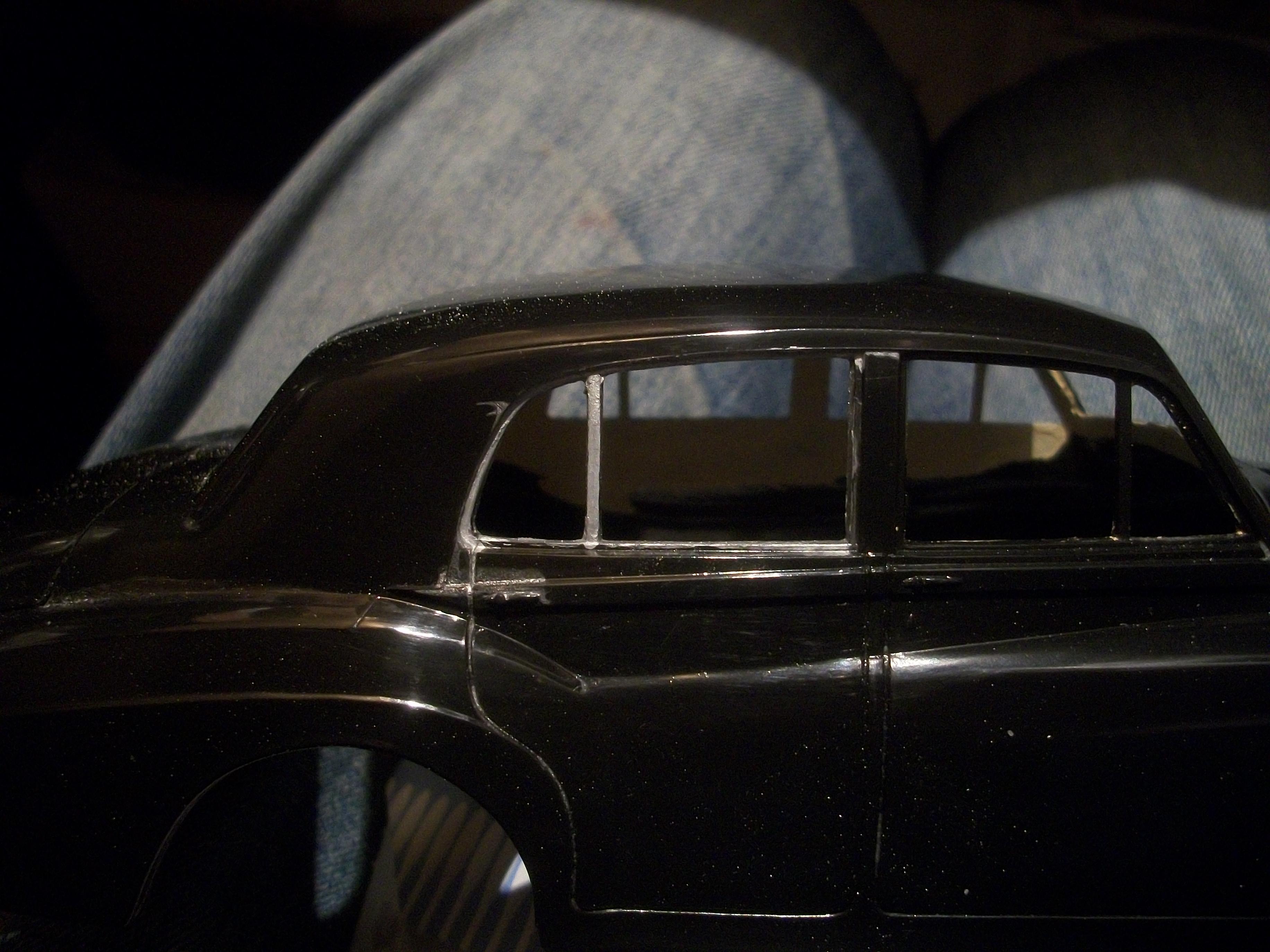
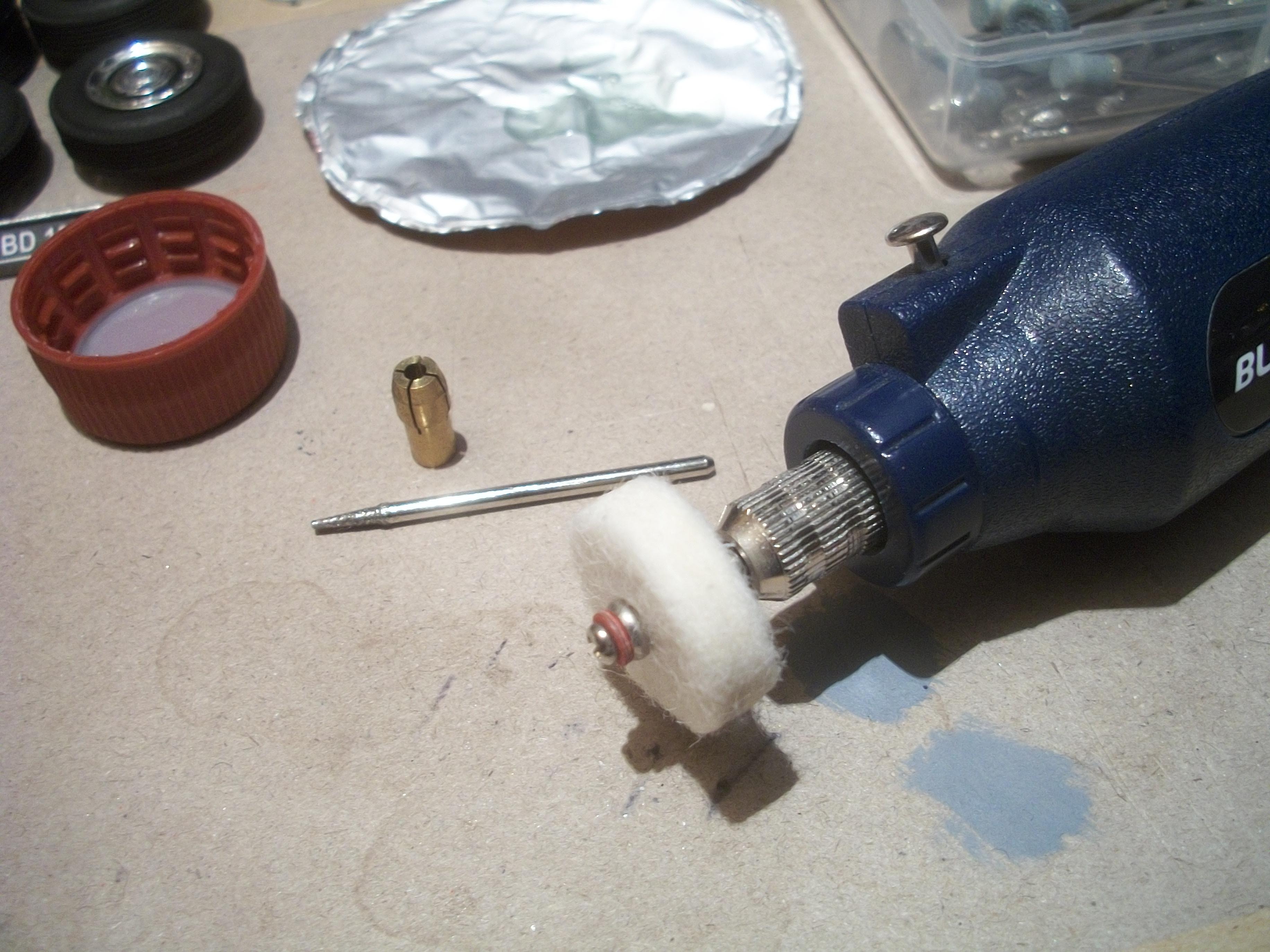
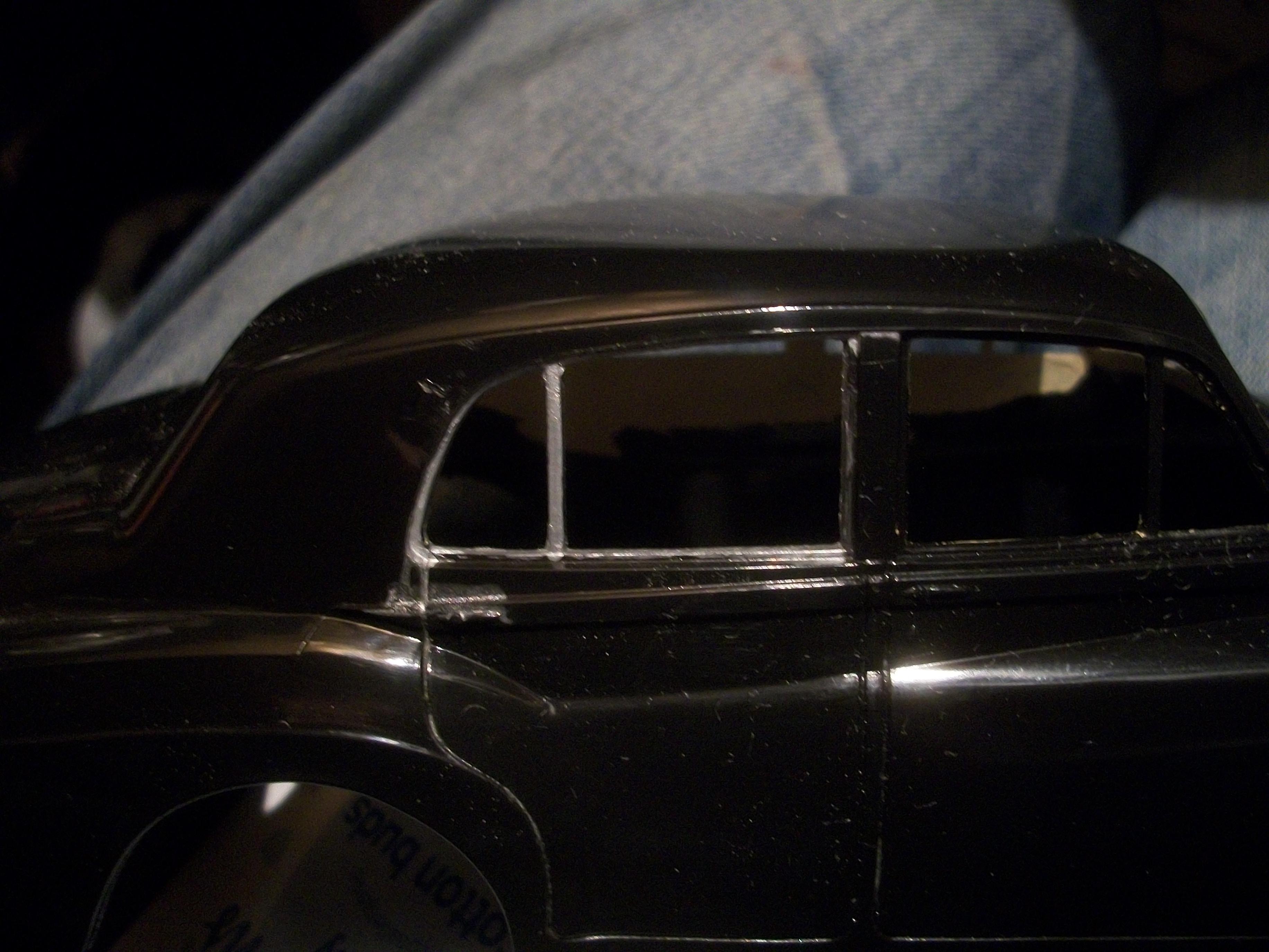
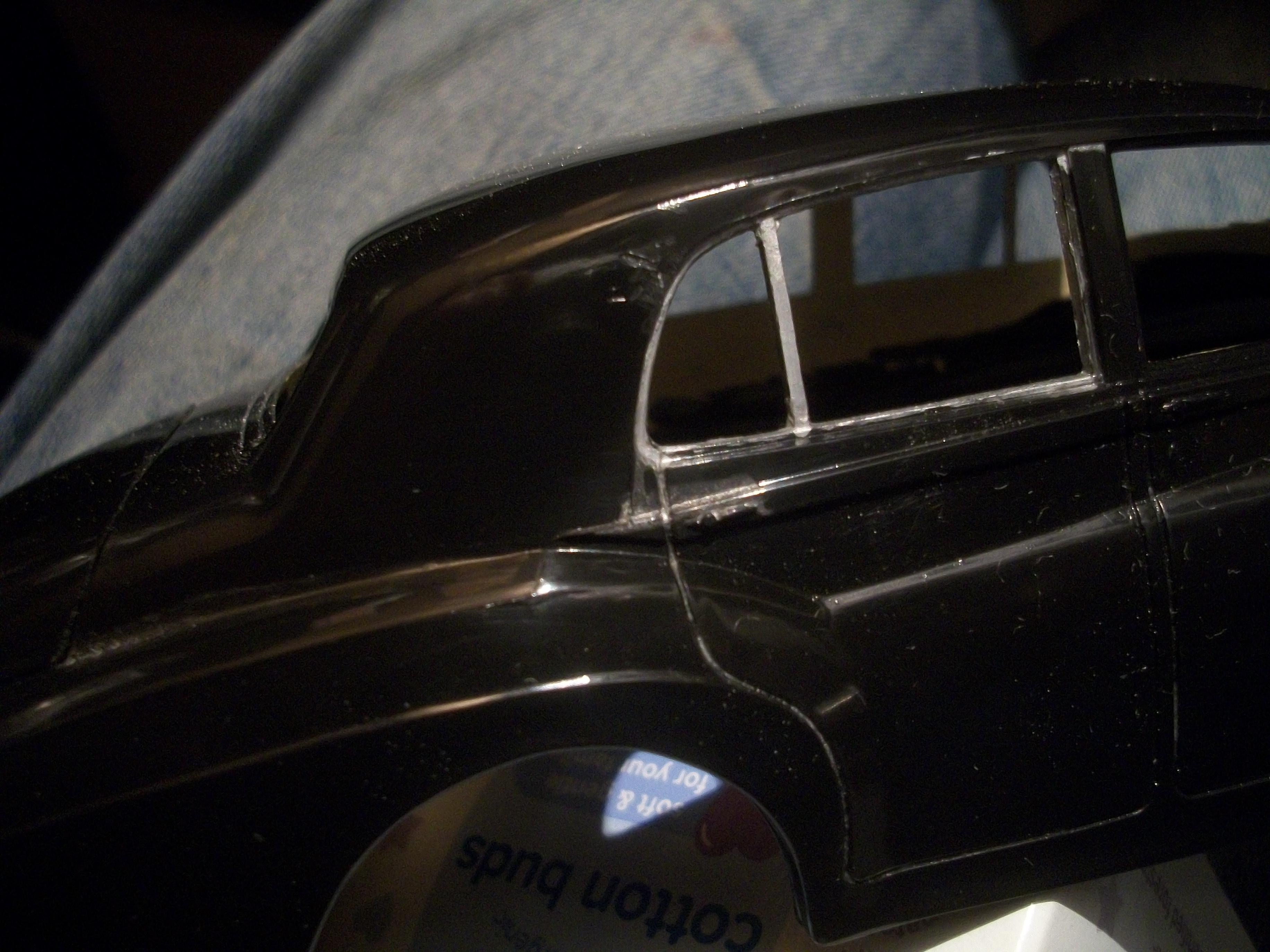
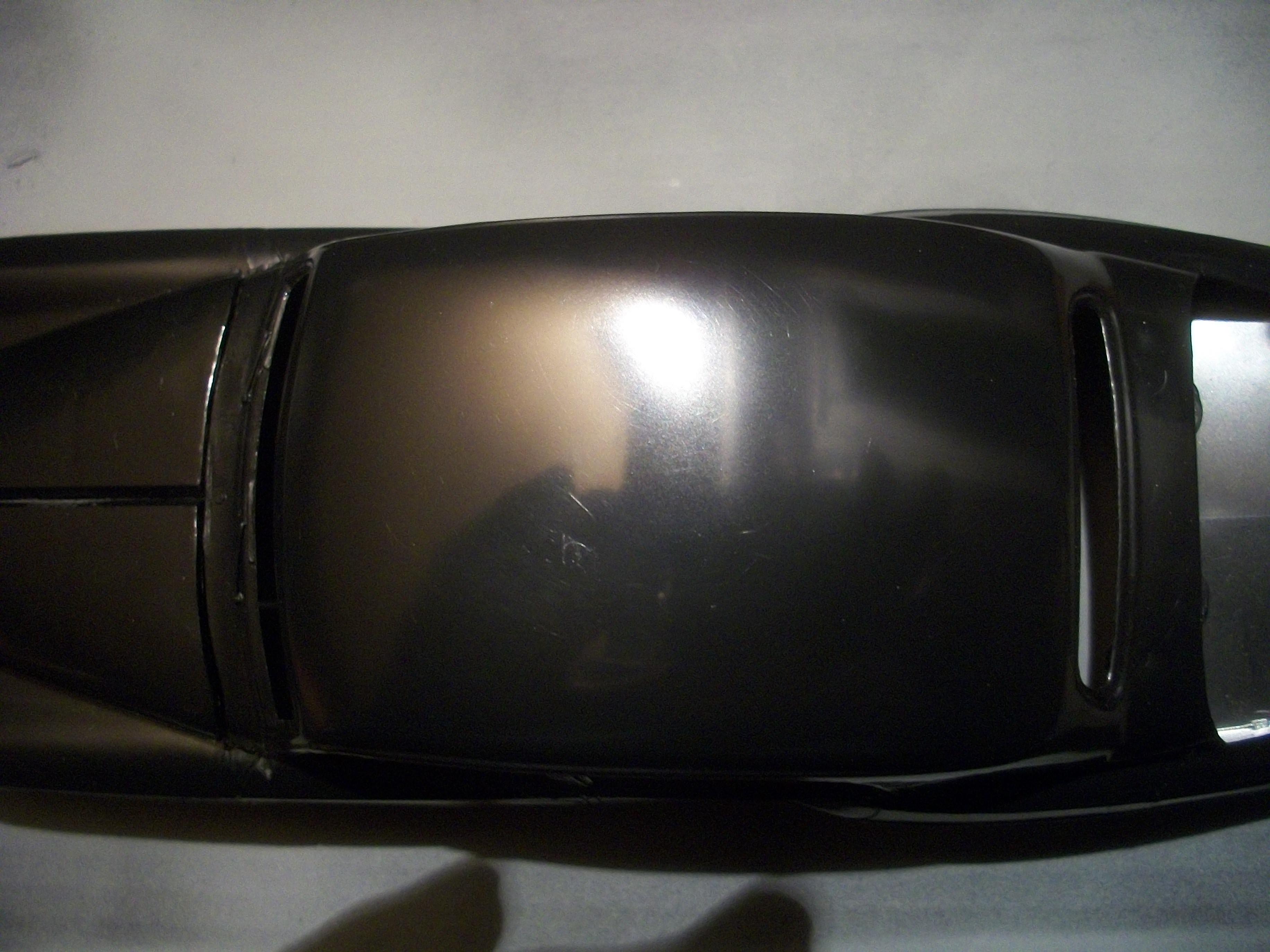
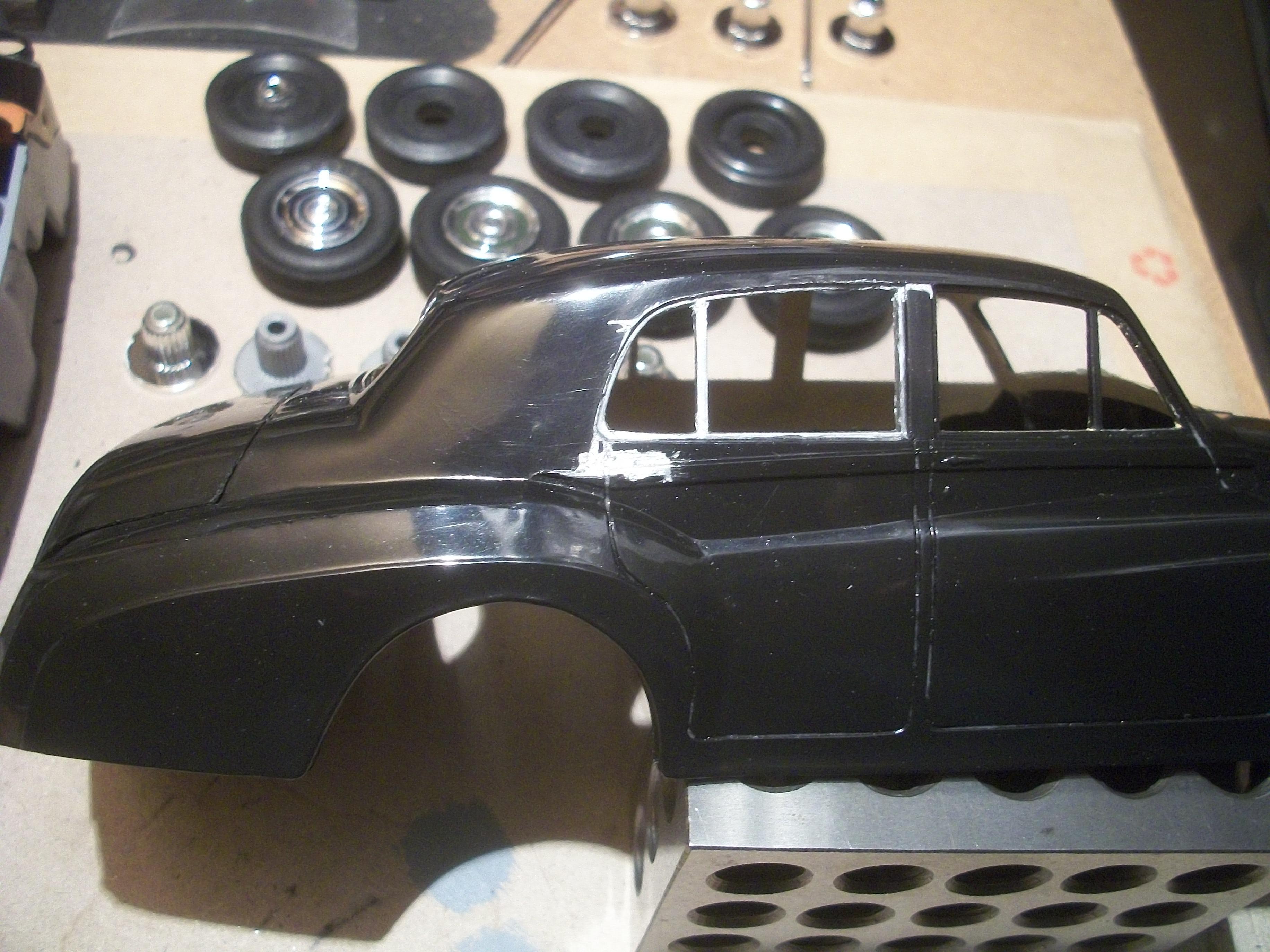
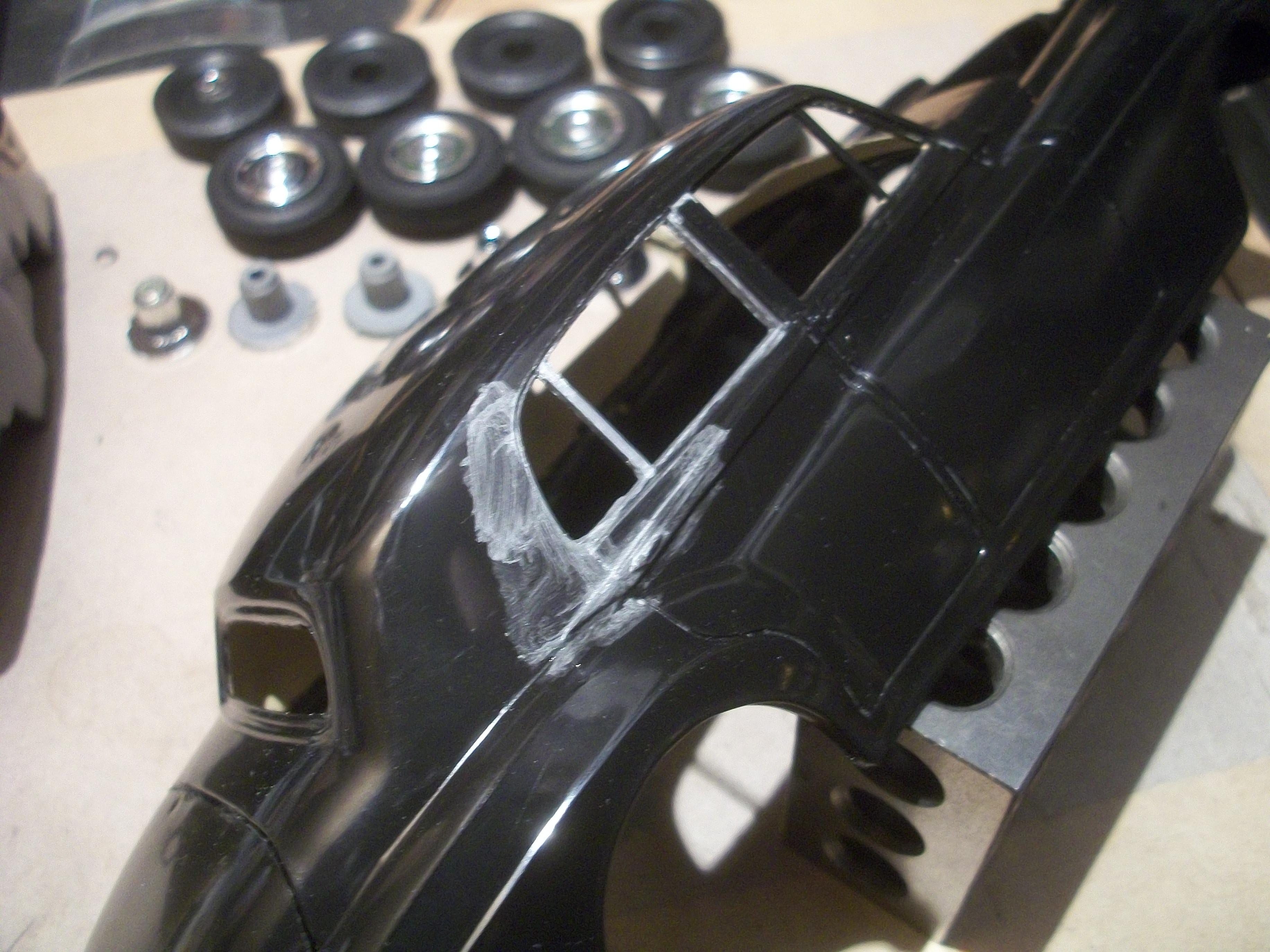
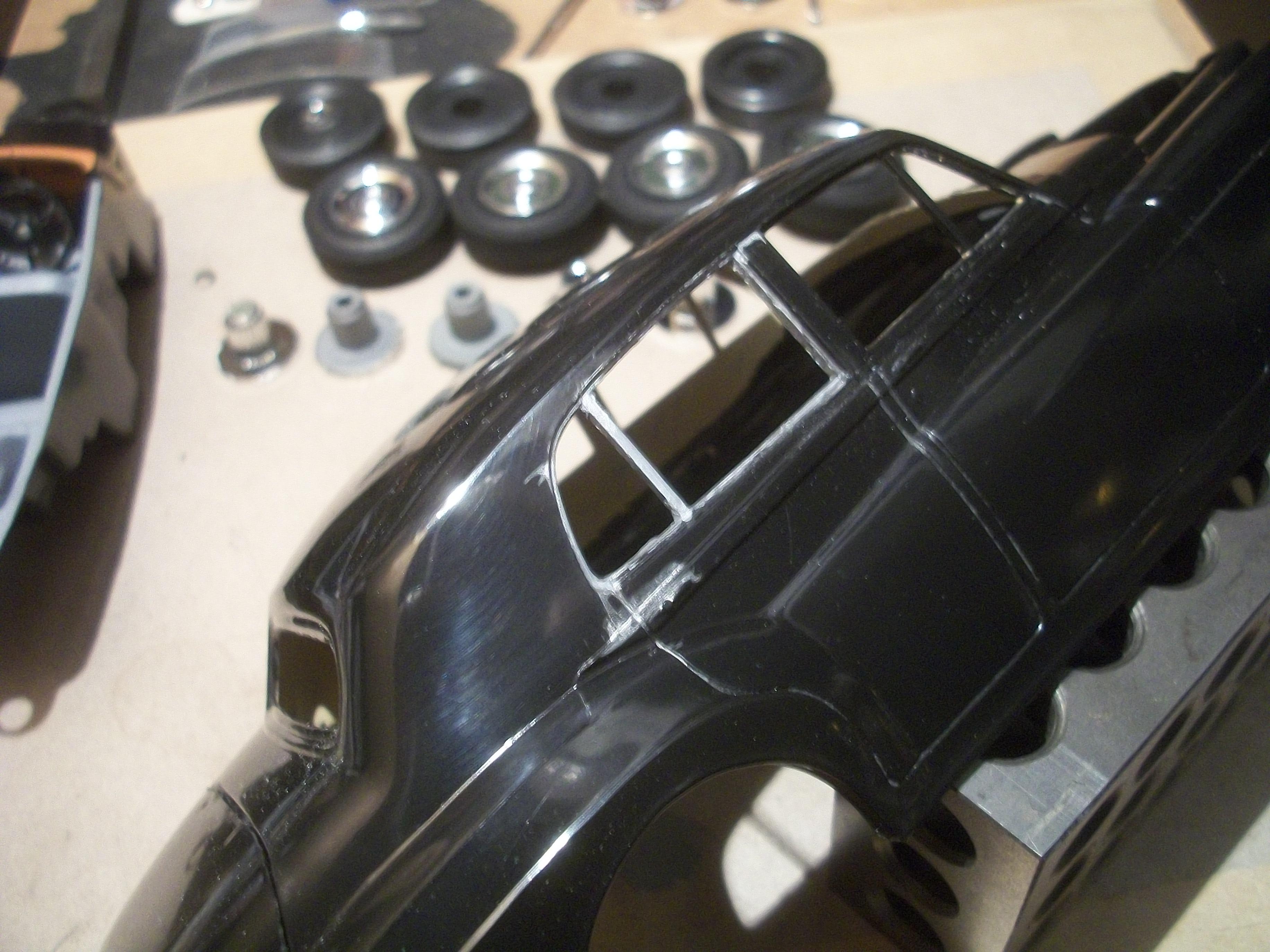
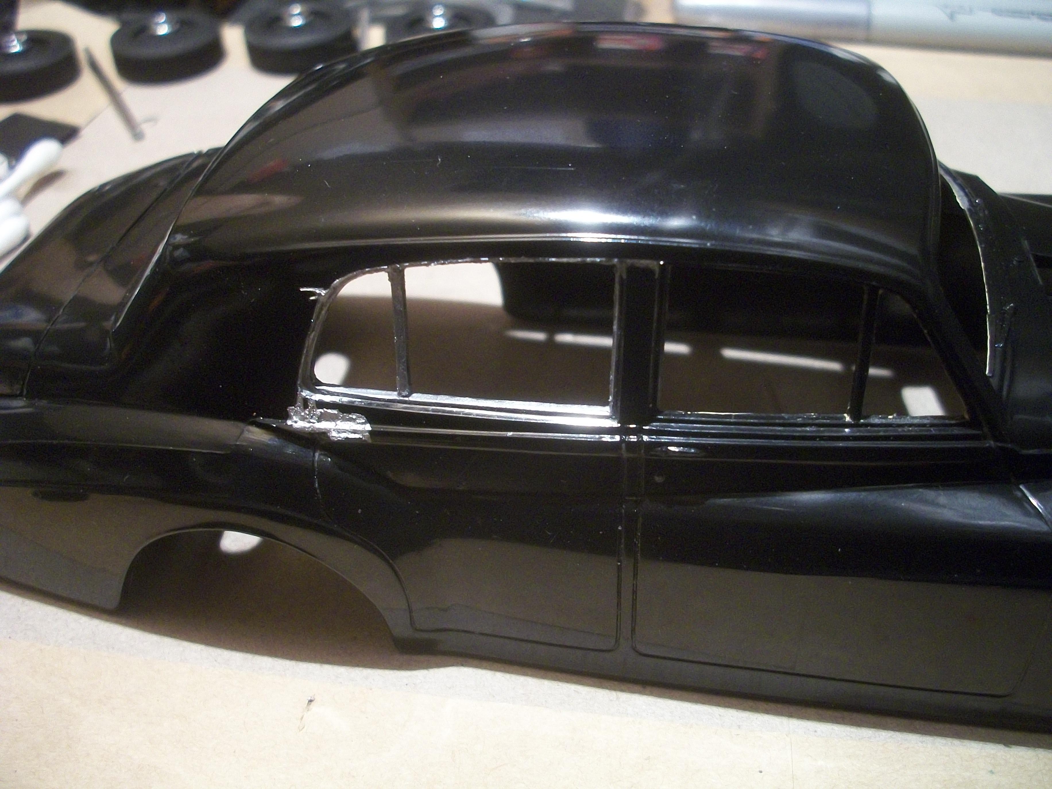
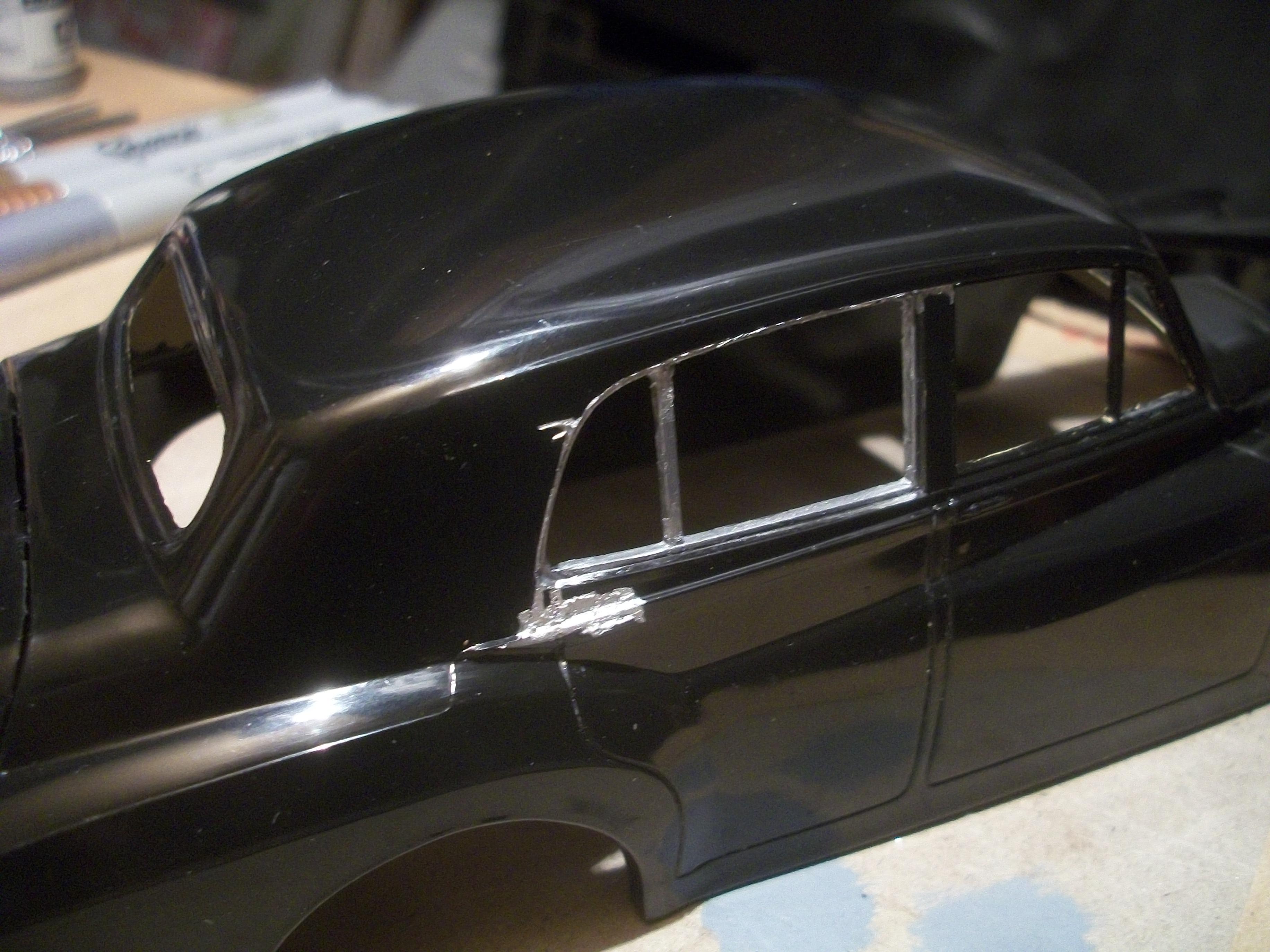
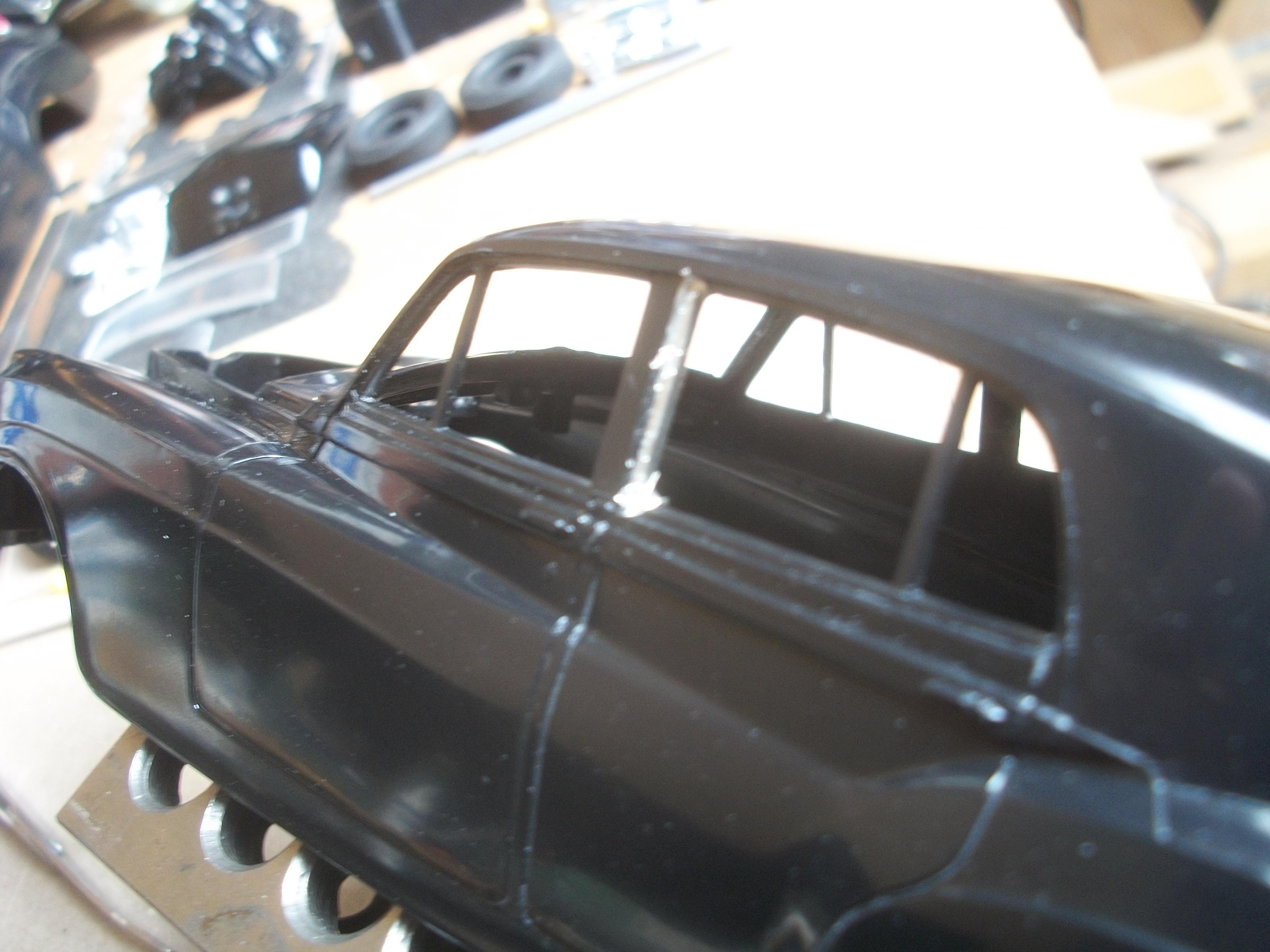
Having tried various different methods to remove the silver Sharpie marker spillage from the bodywork close to the rear quarter light of the Silver Cloud, there were only two options remaining . . . One was to use hand sanitiser, which is basically rubbing alcohol, and the second option would be to use WD40. The first photo of the following batch of photos shows the area of damage after I had tried hand sanitiser. This has actually removed a small amount of the blemish, but not completely removed . . . Then I tried using a buffing pad with my mini grinder tool, but I might have inflicted some additional damage to the plastic. Maybe the buffing pad was spinning too fast, or maybe I exerted too much pressure. The Sharpie marks have not been removed satisfactorily. The only remaining method of removal that I can think of, would be WD40, but I cannot find my can of WD40 anywhere. I shall probably purchase a new can at some point, but I am not hopeful that it will have any effect . . . I have considered using a different body for this build, and I do have four bodies to choose from. However, each of these four bodies has a scratch mark in the plastic of the roof, and due to the fact that I need to polish the bare black plastic rather applying paint, this means that I cannot use any of them. Work on this build has halted, while I come up with Plan B . . . if indeed there is a Plan B. David
-
Rolls-Royce No Chemicals, No Paint, No Harmful Glues
Anglia105E replied to Anglia105E's topic in WIP: Model Cars
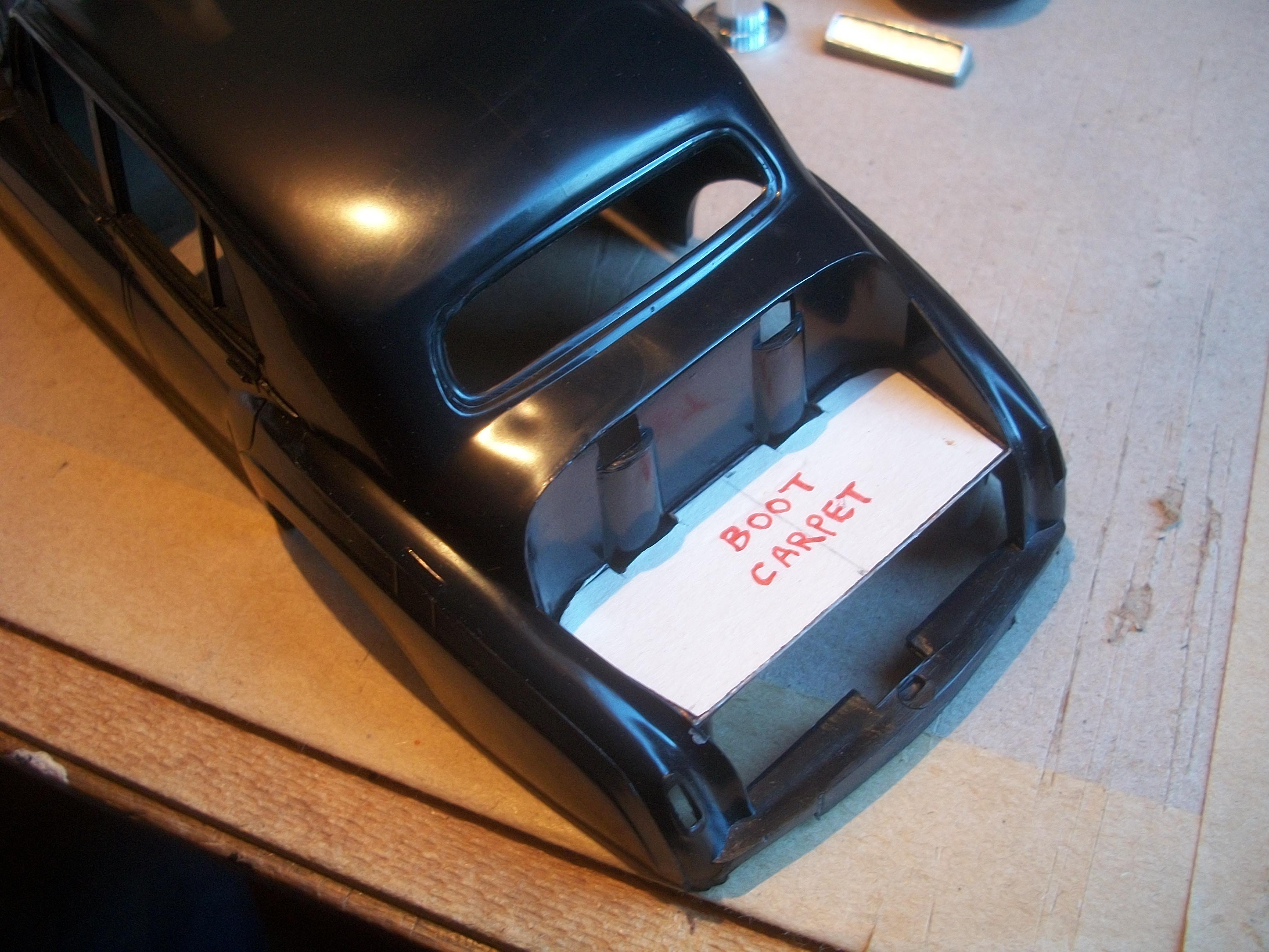
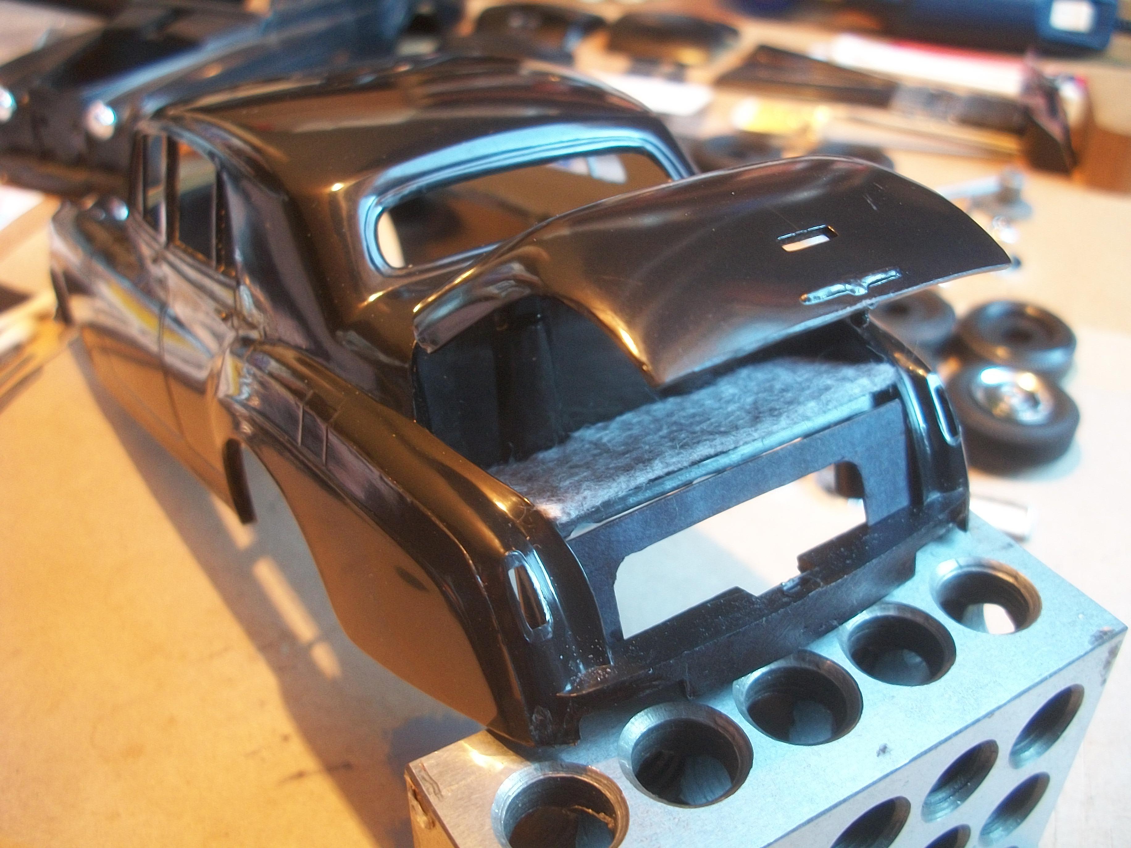
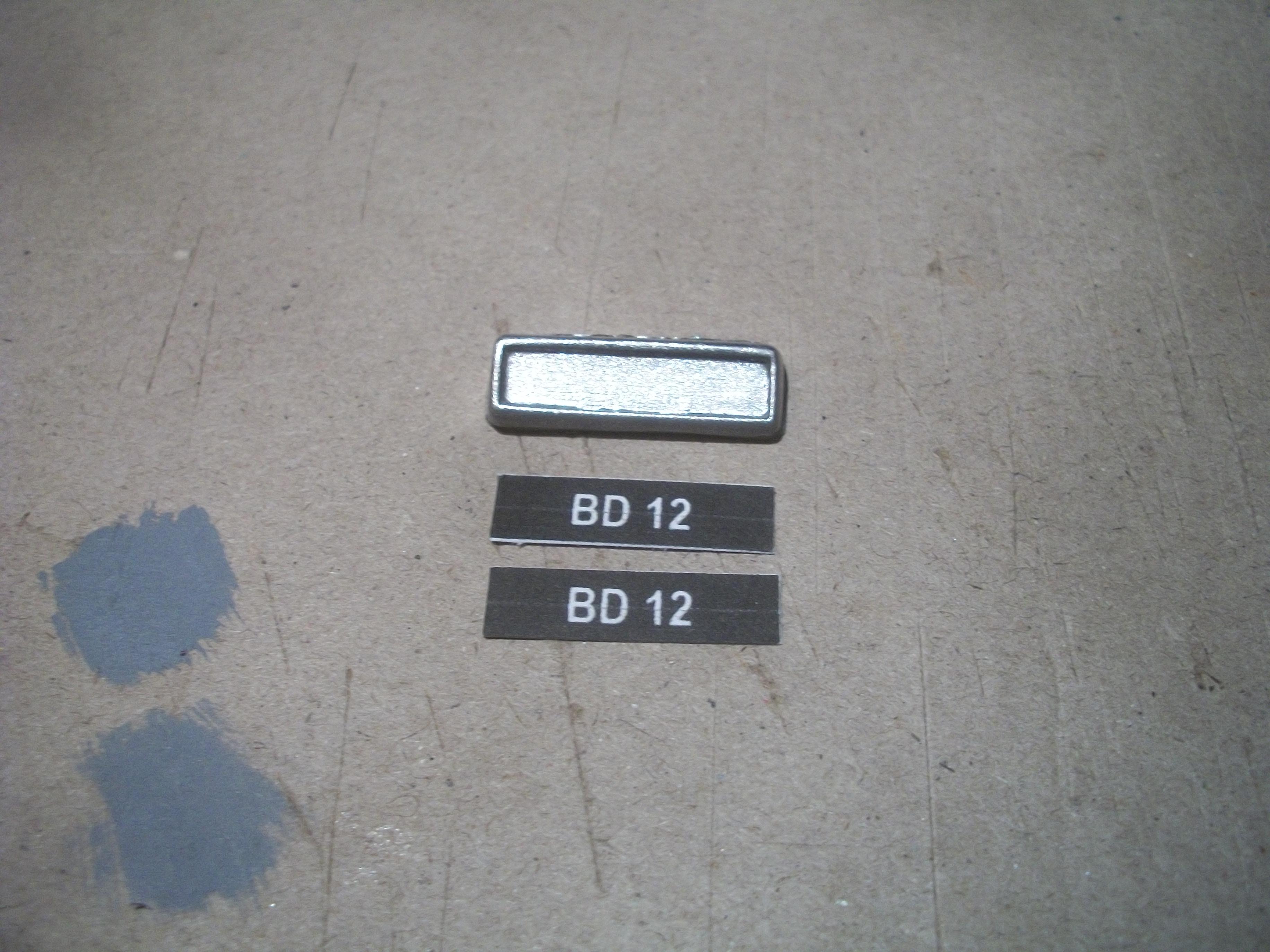
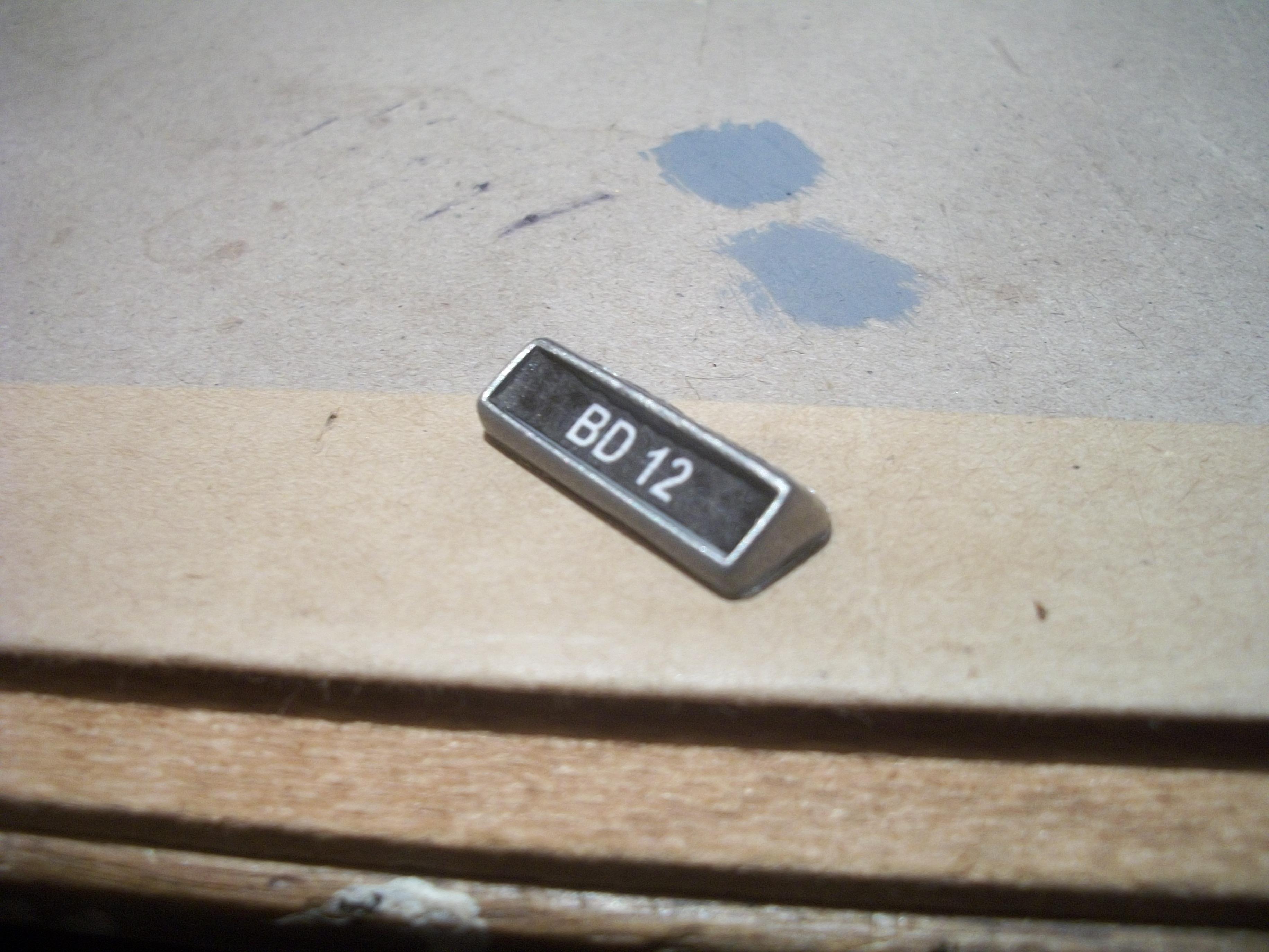
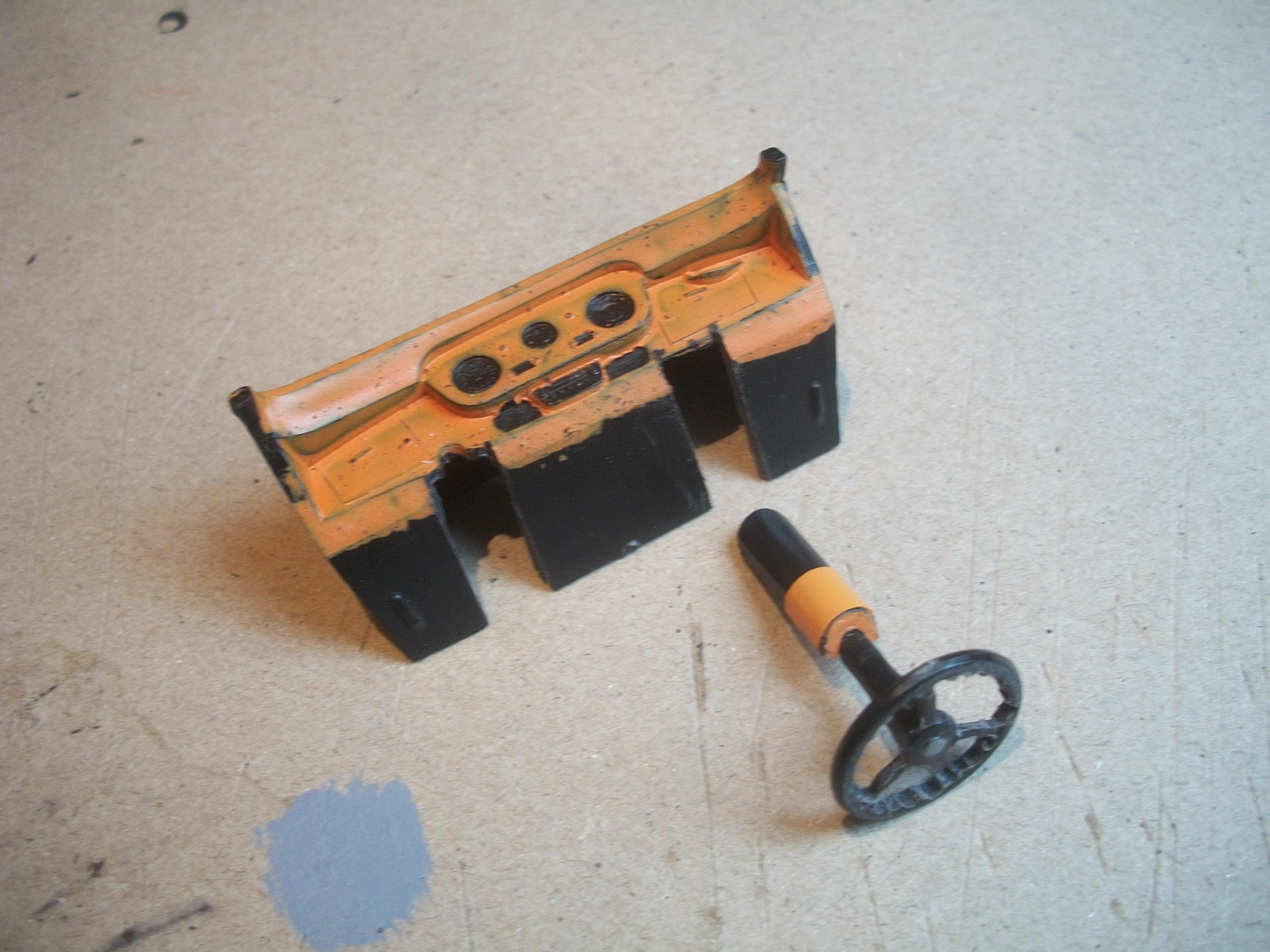
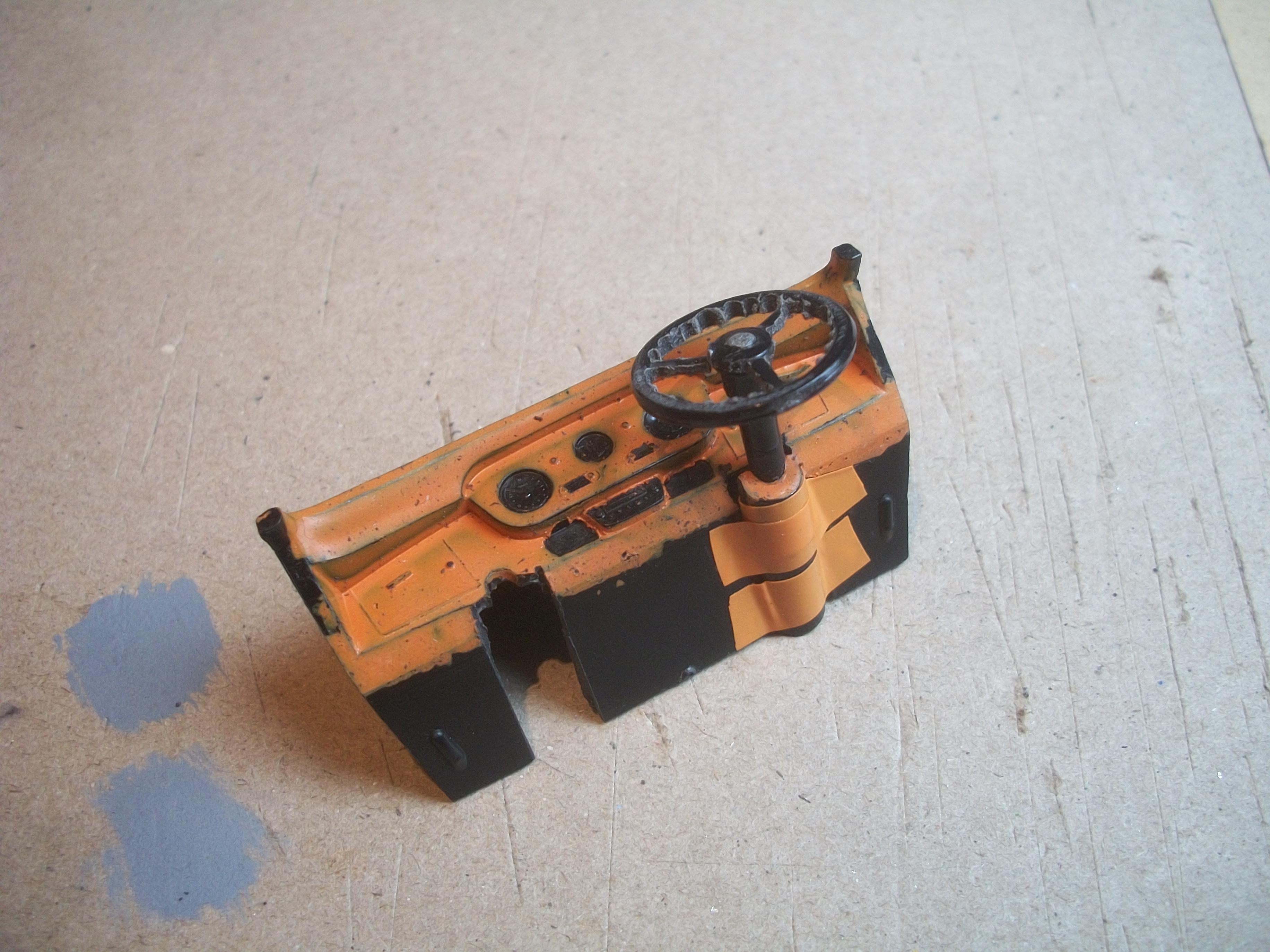
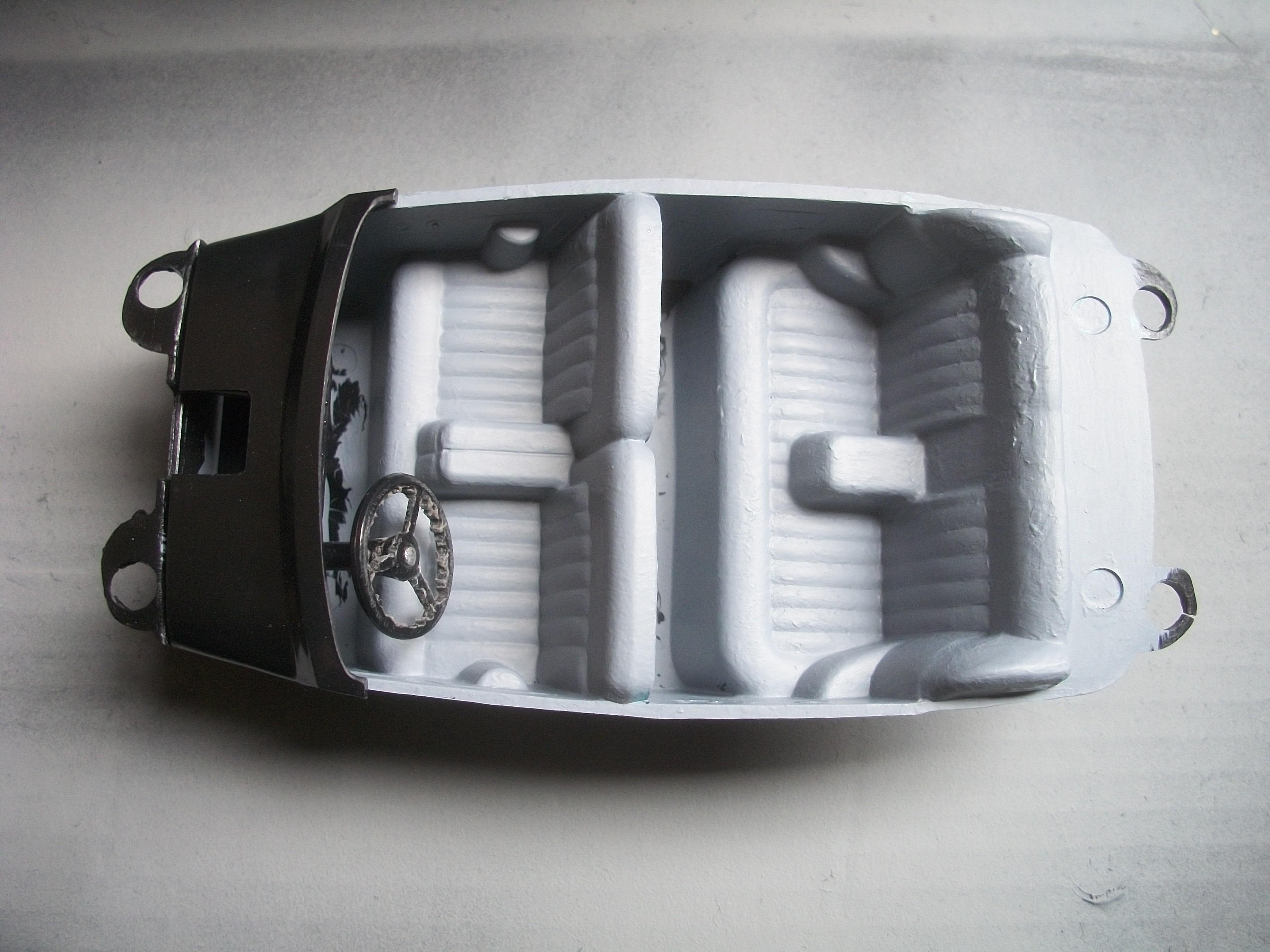
The steering column was removed from the dashboard and I enlarged the hole for the mounting tube, so that a different steering column could be mounted. This one has a steering wheel that is smooth, with no cutouts inside the rim . . . The steering wheel was touching the driver's seat cushion previously but does not touch the seat now. Having picked up some grey felt material today, I used my boot carpet template to cut out a piece of carpet. This was then test fitted inside the boot floor, and the spare wheel black surround panel was also test fitted. Both look good . . . I printed out two number plates for the registration plate ' BD 12 ' in white on black, and cut them to size 22 mm x 5 mm. One of the printed plates was then PVA glued onto the rear number plate plinth and left to set overnight . . . David
-
Rolls-Royce No Chemicals, No Paint, No Harmful Glues
Anglia105E replied to Anglia105E's topic in WIP: Model Cars
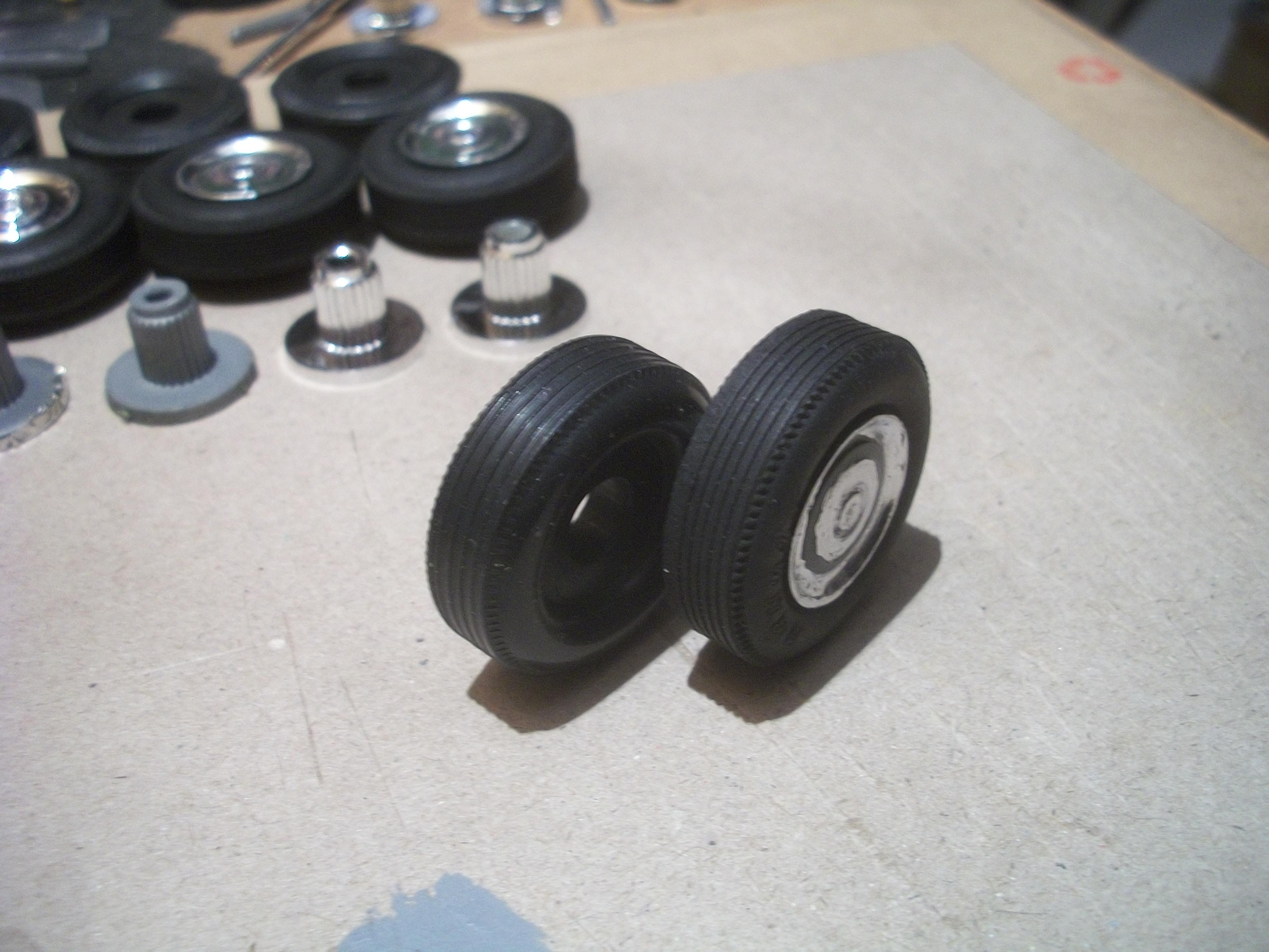
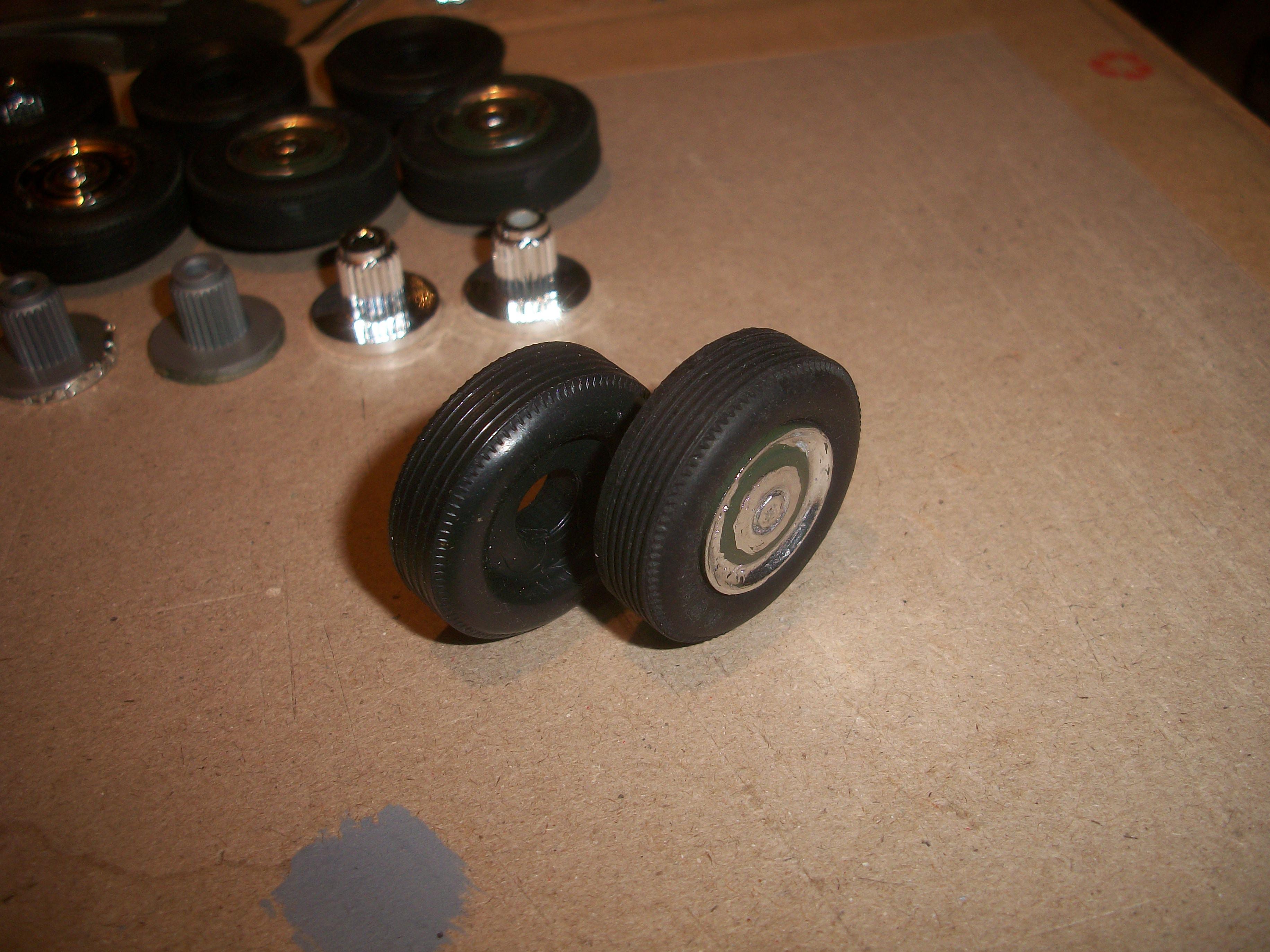
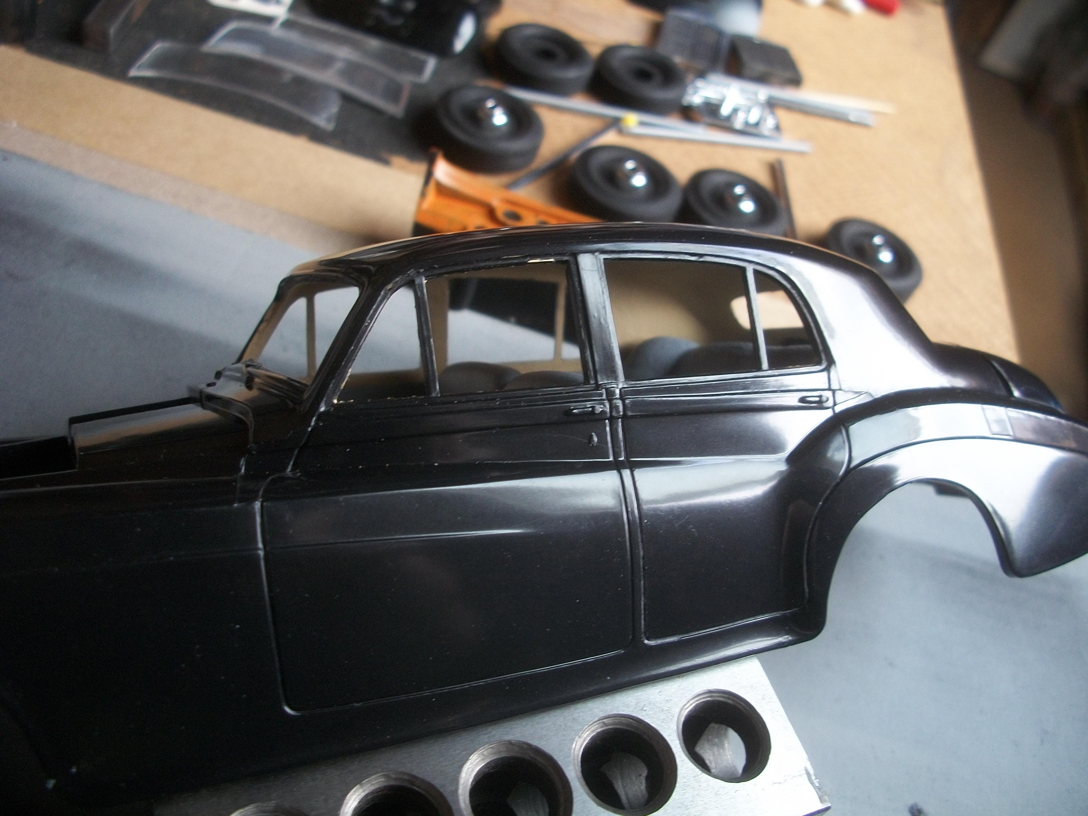
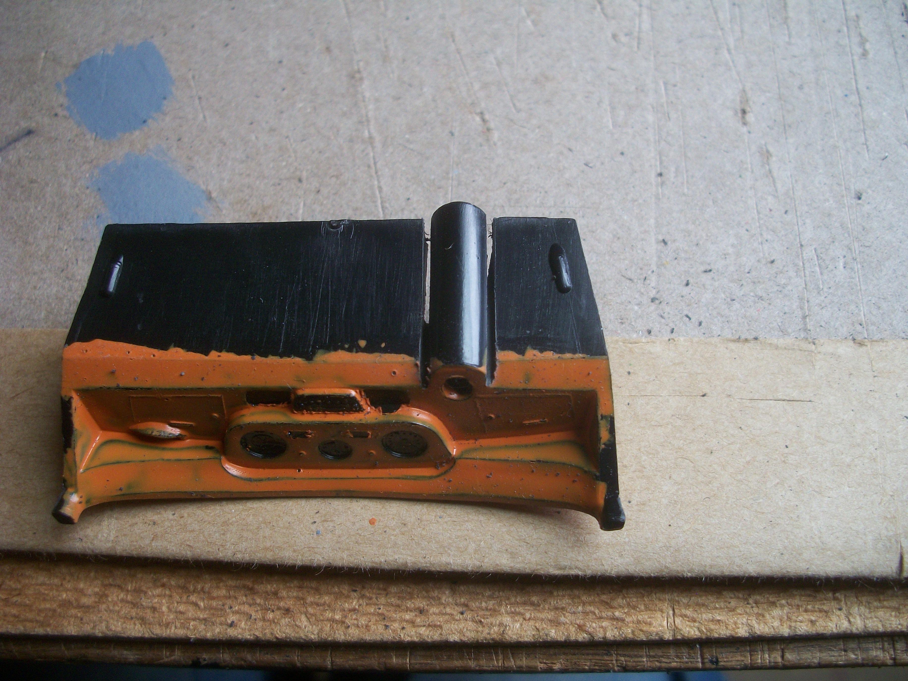
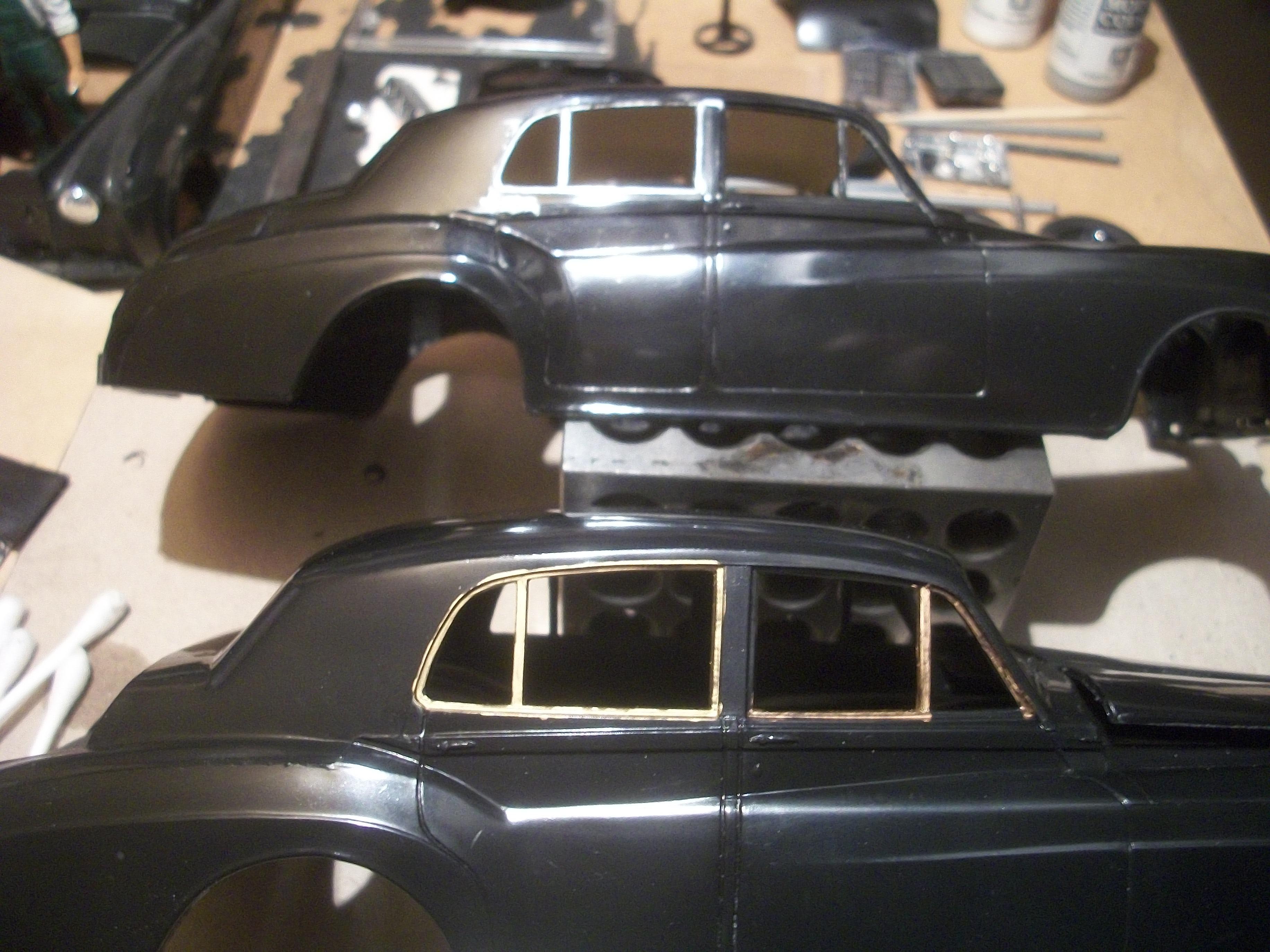
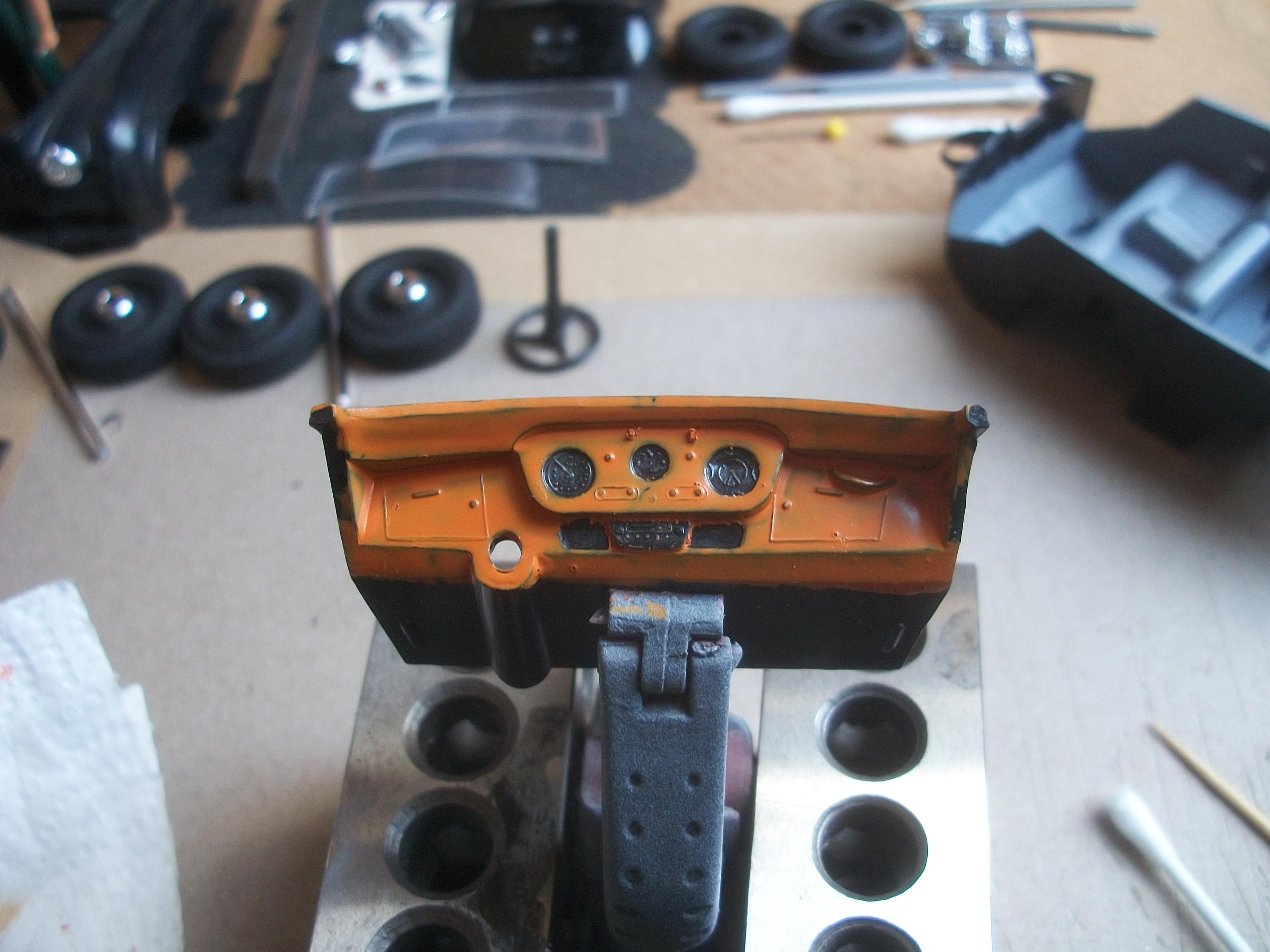
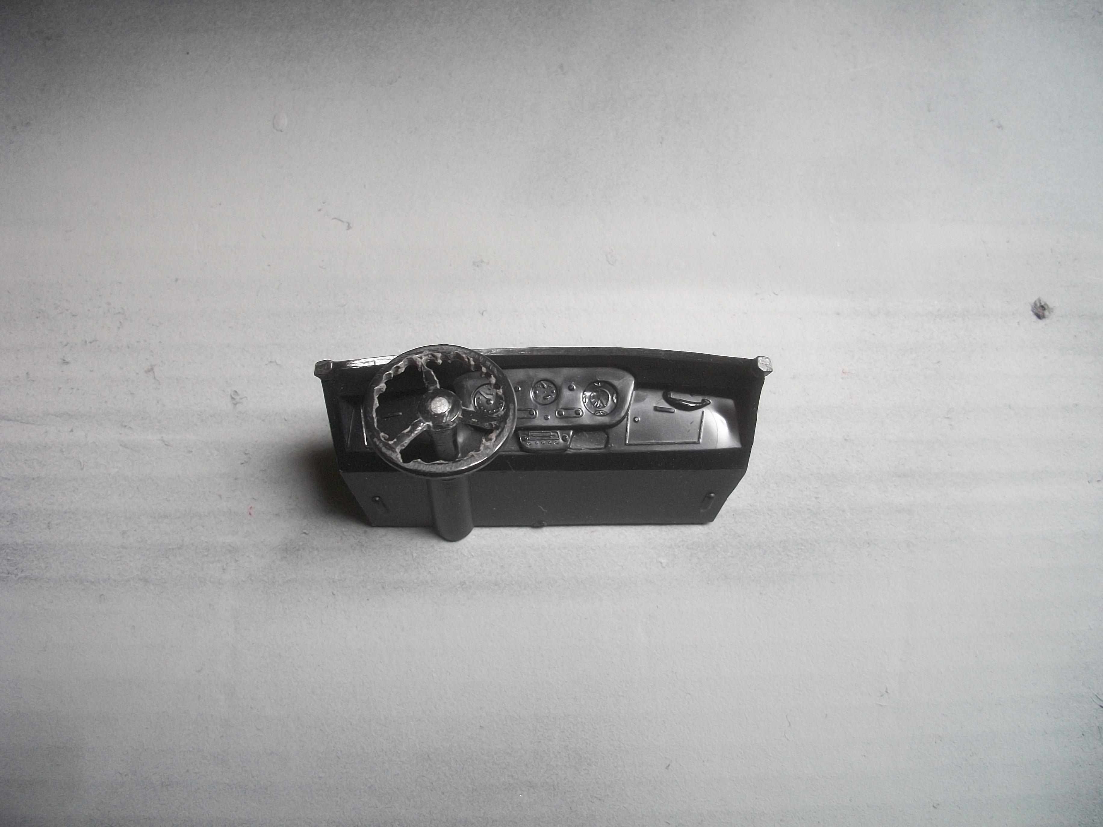
As the following photos show, I used some baking powder toothpaste applied to the leaked silver Sharpie on the bodywork, and this was followed by wiping off the area with micro fibre cloth and distilled malt vinegar . . . Then I had the idea to apply a small amount of Meguiars Carnauba Wax polish to the same area, which was again wiped clean with the vinegar. Although this process has removed most of the Sharpie spillage, the end result is not perfect by any means. This area of damage is simply not good enough for a Rolls-Royce . . . Maybe as I have five body shells for the Silver Cloud available to me, I should use a different body altogether? The last two photos show the difference between the two tyres, which is the one on the left being a Minicraft tyre and the one on the right is the tyre that would be found in a Revell kit or an Entex kit . . . The Revell / Entex version of this tyre is much more realistic in appearance, and has more of a rubber look to it than the Minicraft version, as well as being slight bulkier . . . I realised only this evening, that the dashboard is not right . . . I have moved the position of the steering column from LHD to RHD, but the speedometer gauge is on the left of the three gauges, which is correct for a LHD motor car, but the speedo should be on the right of the the three gauges for a RHD motor car. Not sure yet how I shall rectify this error, but there must be a way, there always is . . . David
-
Rolls-Royce No Chemicals, No Paint, No Harmful Glues
Anglia105E replied to Anglia105E's topic in WIP: Model Cars
Yes, I will be looking for those signs . . . Many articles suggest checking underneath refrigerators, and behind as well as underneath any furniture that never moves, including beds . . . -
Rolls-Royce No Chemicals, No Paint, No Harmful Glues
Anglia105E replied to Anglia105E's topic in WIP: Model Cars
I hope your health continues to improve John, and I shall take steps to overcome this bacterial attack on my property ! -
Rolls-Royce No Chemicals, No Paint, No Harmful Glues
Anglia105E replied to Anglia105E's topic in WIP: Model Cars
Thanks John . . . This is the first time in eight years that a Sharpie pen has leaked in the same way that a Molotow Liquid Chrome pen would do. Yes, I do have three packs of Bare Metal Foil, but they are well past their sell by date so not sticking well. I do like the BMF product, but at the moment there are suppliers in the UK showing no stock, or the price is too high for me . . . So I now have some aluminium kitchen foil, which I shall try with PVA glue. I am beginning to believe that the problem inside my house is more than likely going to be mold ( or mould ) and of course I need to deal with that possibility. My first course of action will be to spray white vinegar all around the areas where there could be mold, and then I will take it from there. Really, I don't want to come into close contact with whatever is causing my lung condition, even with a protective mask . . . David -
Rolls-Royce No Chemicals, No Paint, No Harmful Glues
Anglia105E replied to Anglia105E's topic in WIP: Model Cars
Thanks for the tip Jose, but Isopropyl Alcohol is one of the chemicals that I cannot use . . . I think it would remove the metallic silver Sharpie. The only other option that I have is my baking soda toothpaste ! David -
Rolls-Royce No Chemicals, No Paint, No Harmful Glues
Anglia105E replied to Anglia105E's topic in WIP: Model Cars
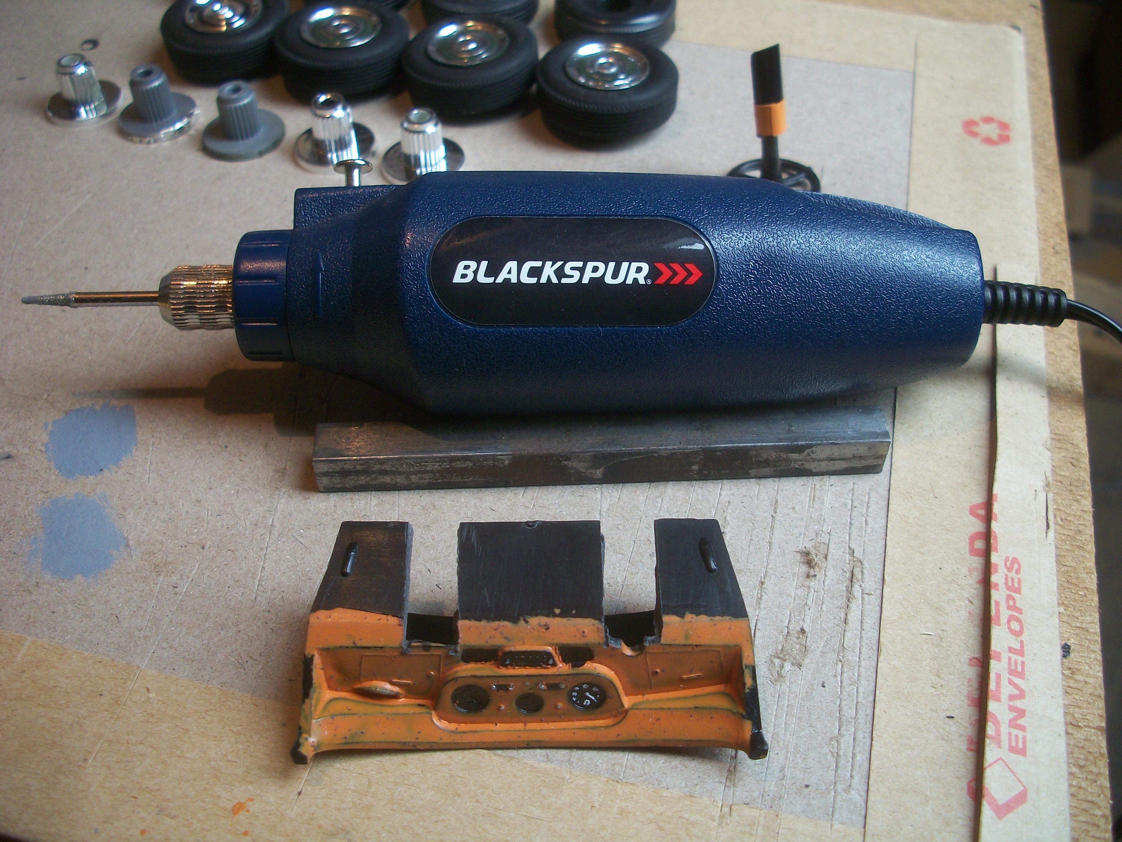
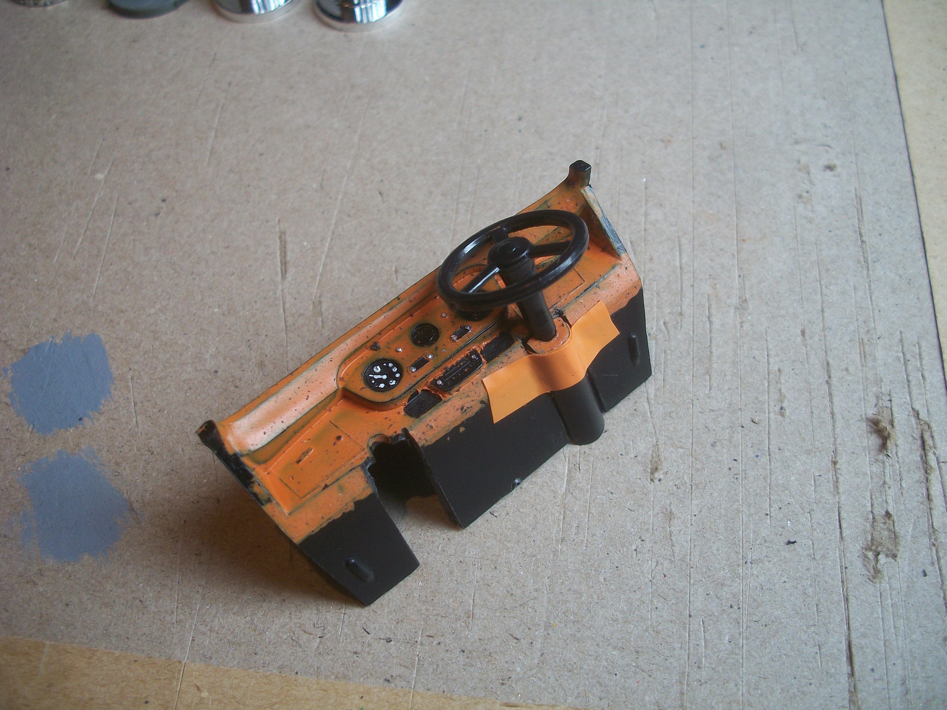
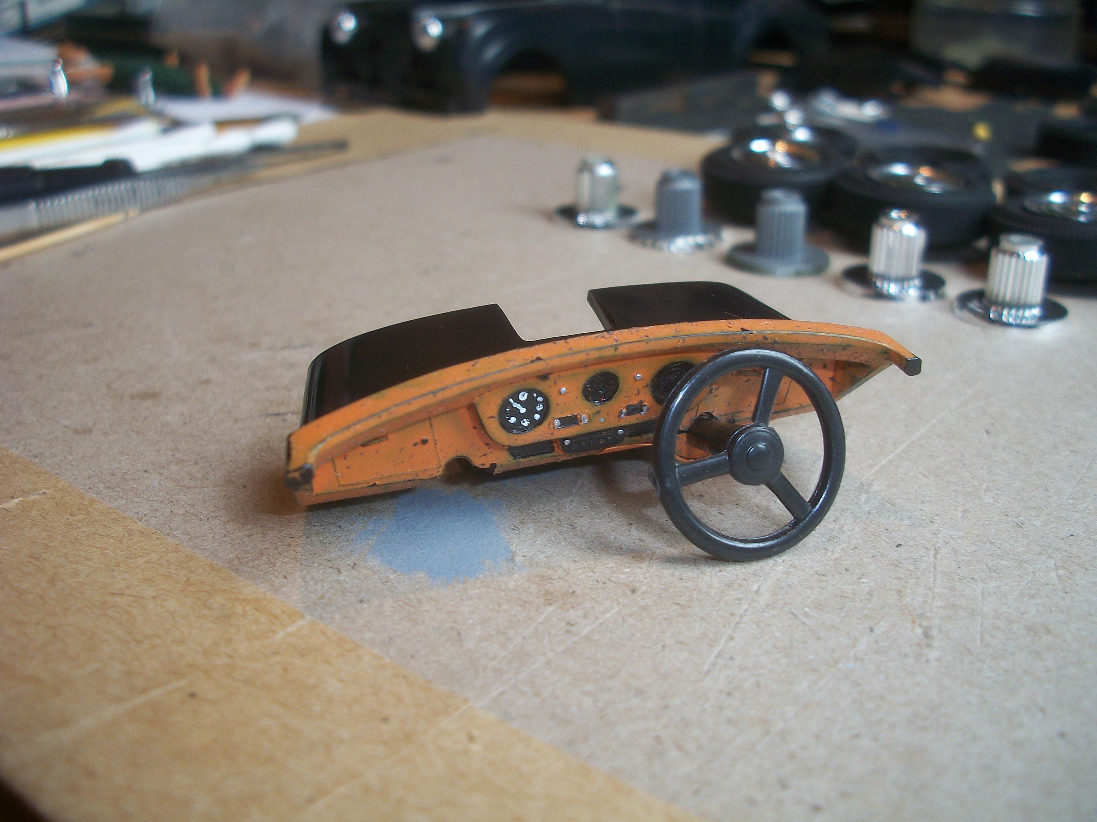
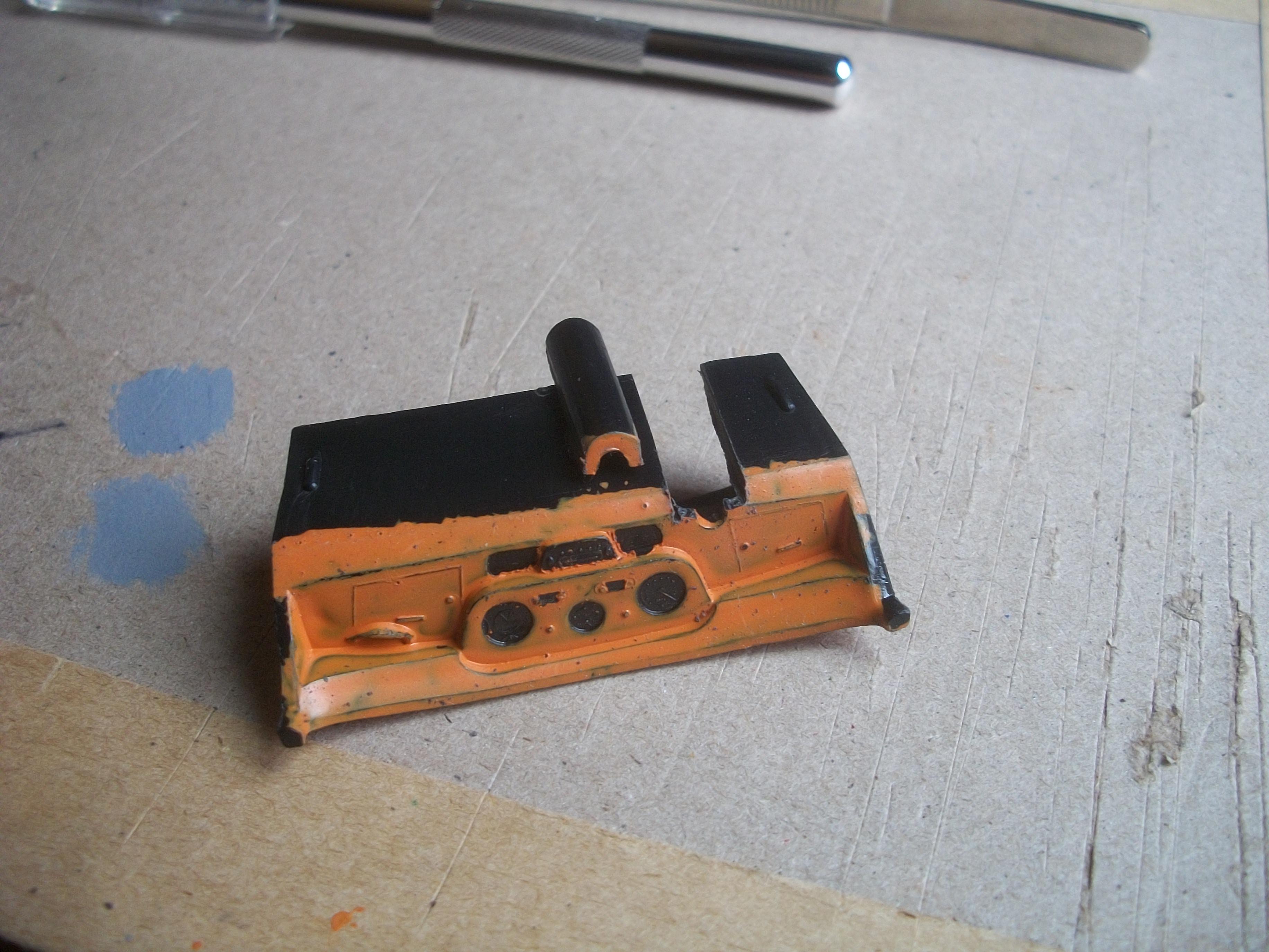
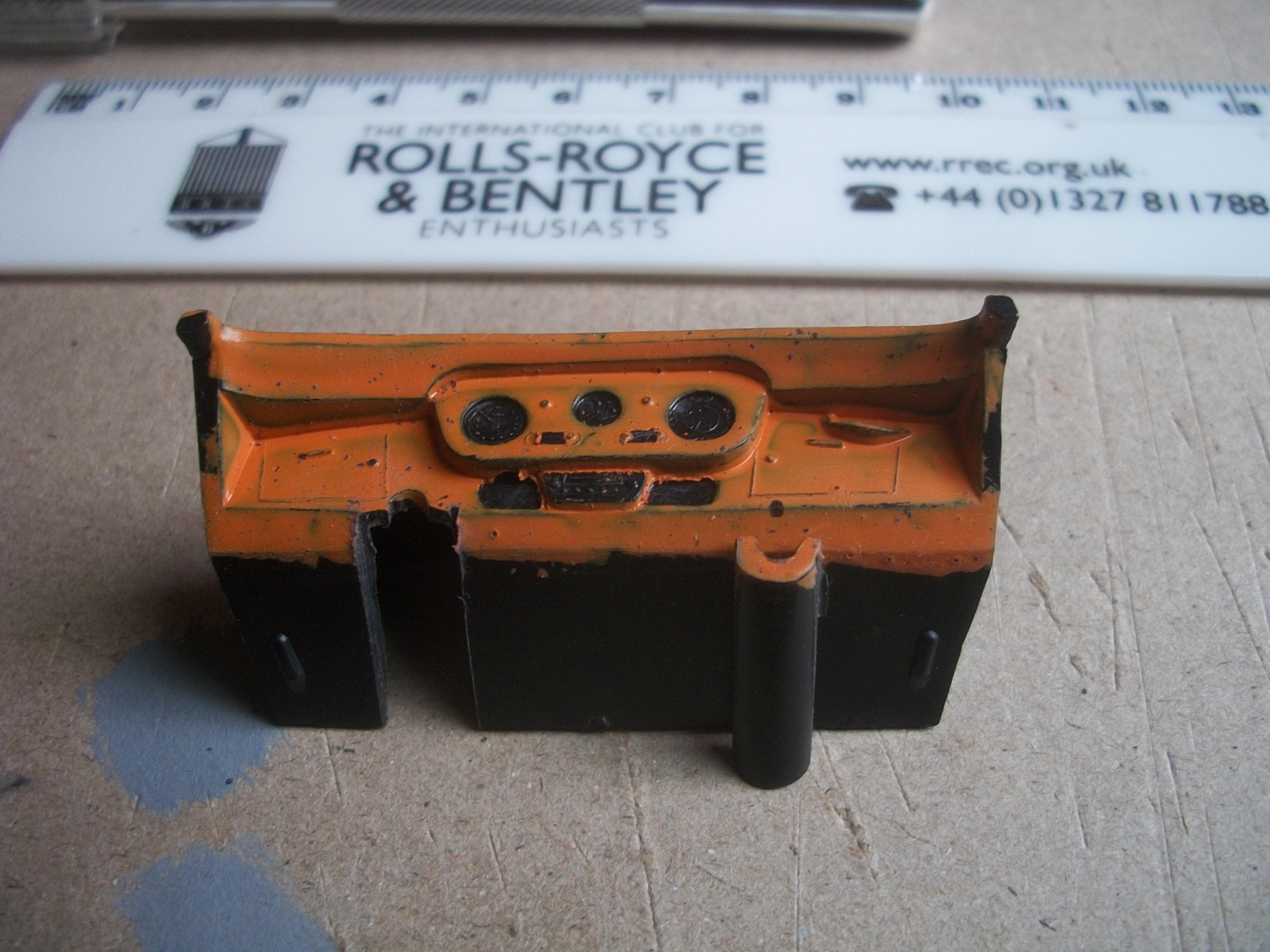
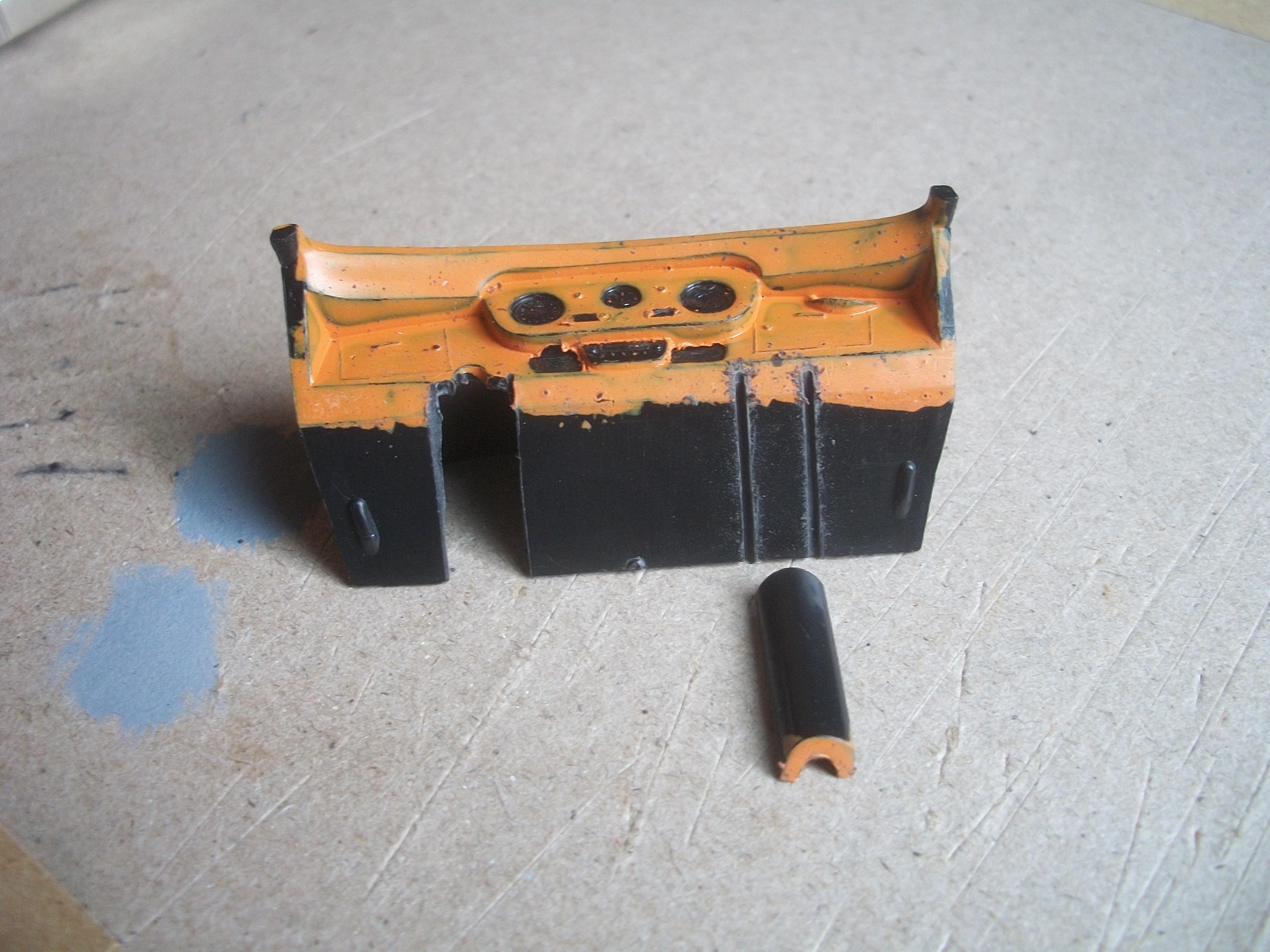
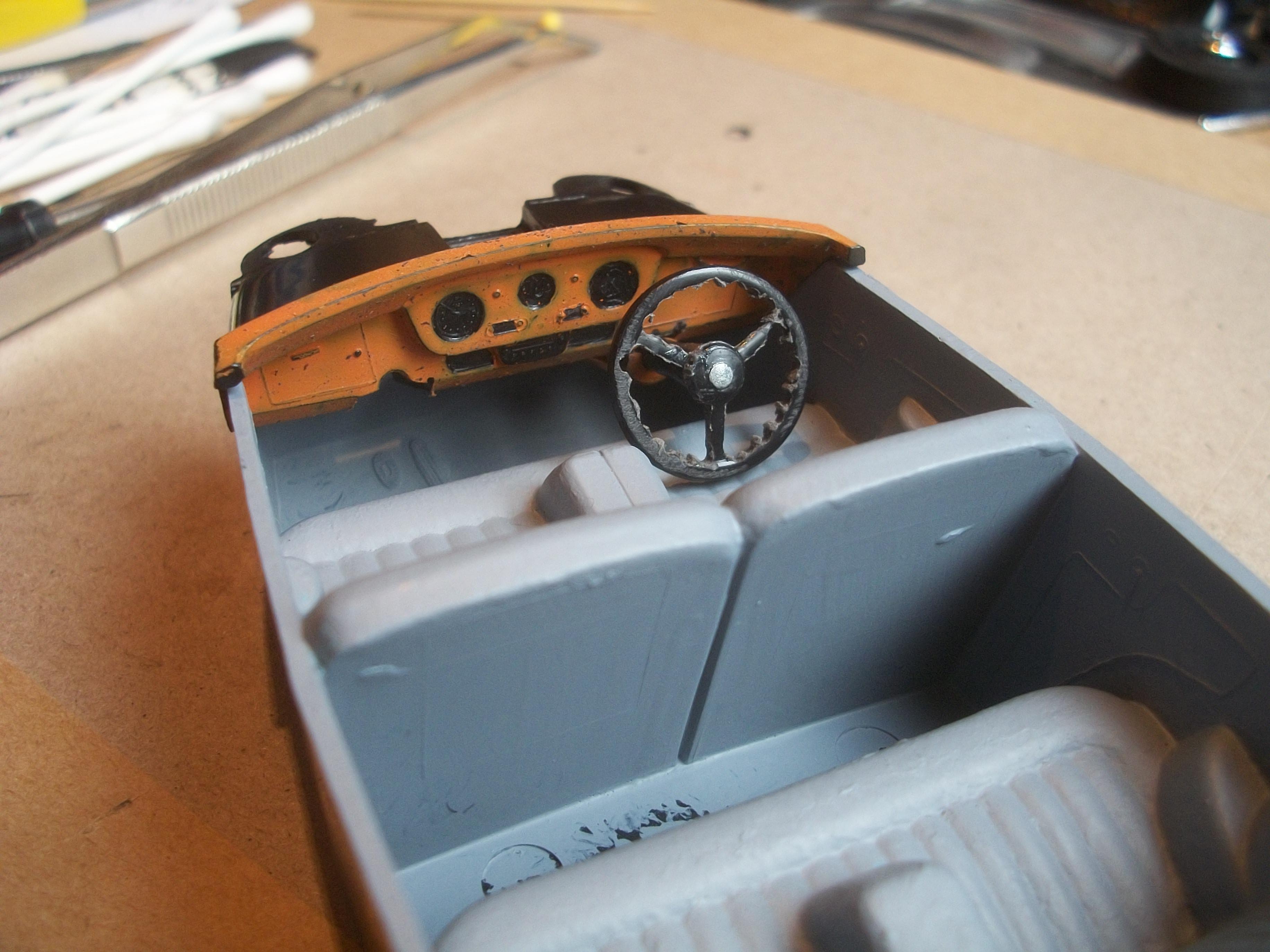
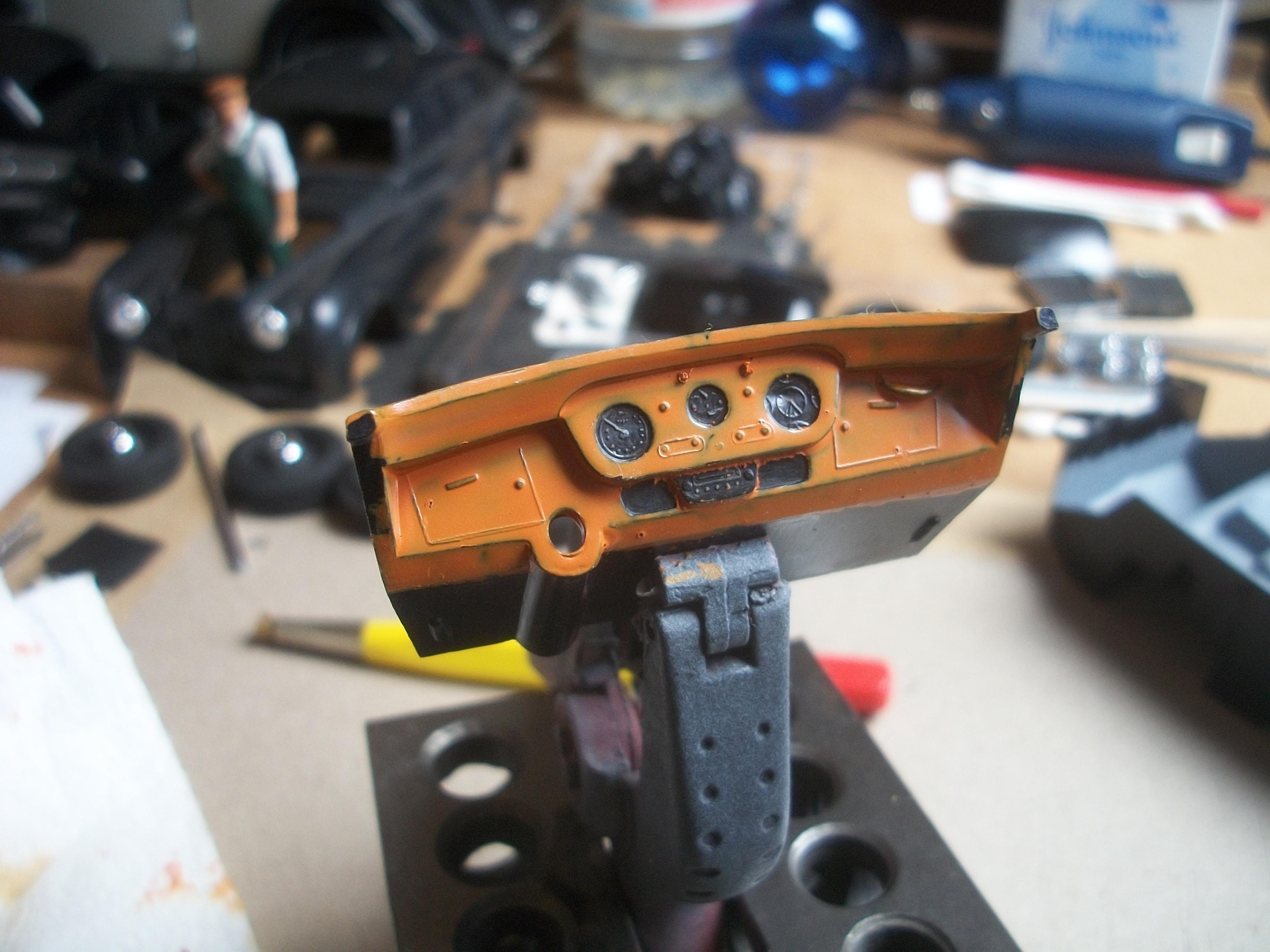
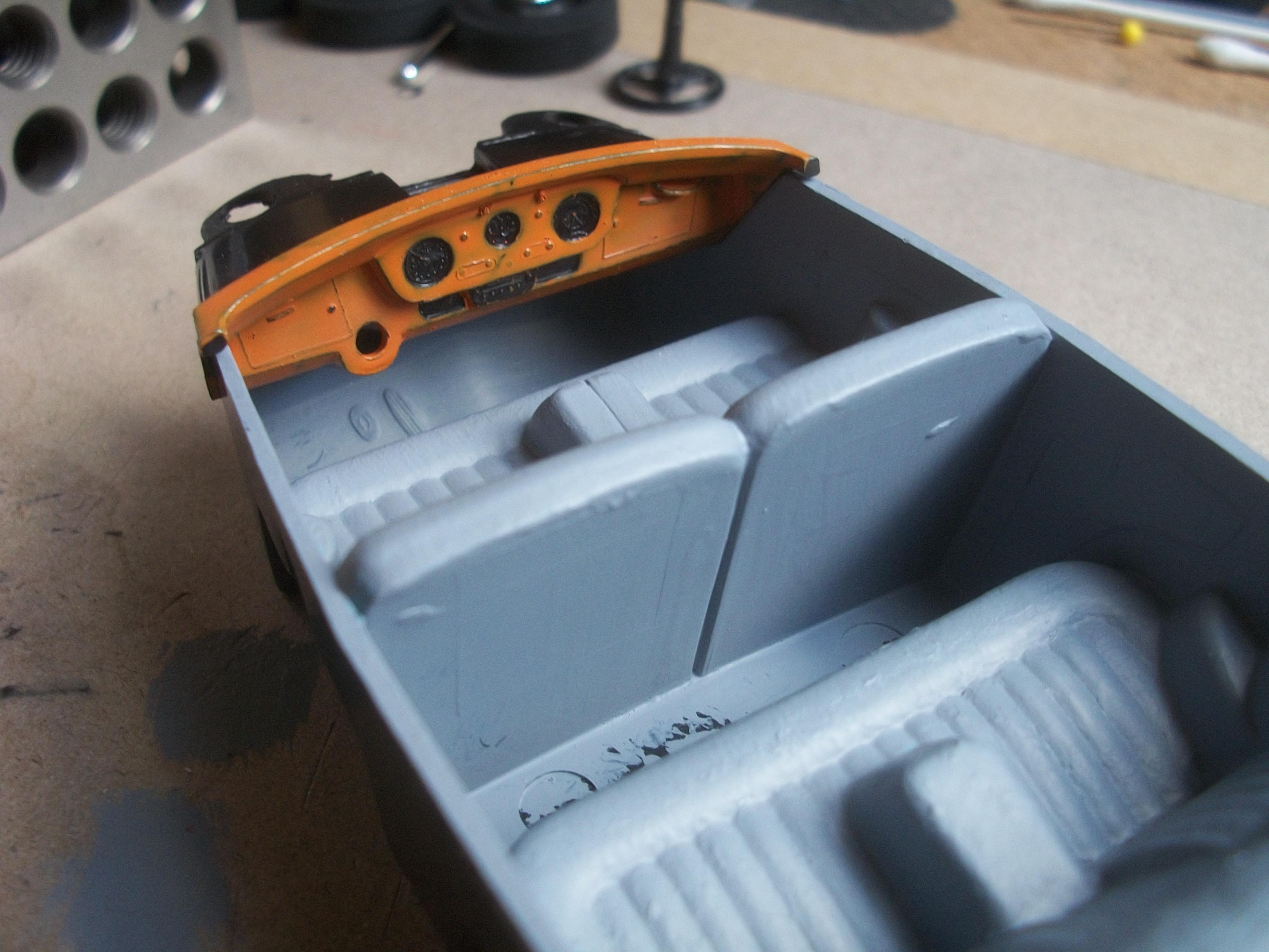
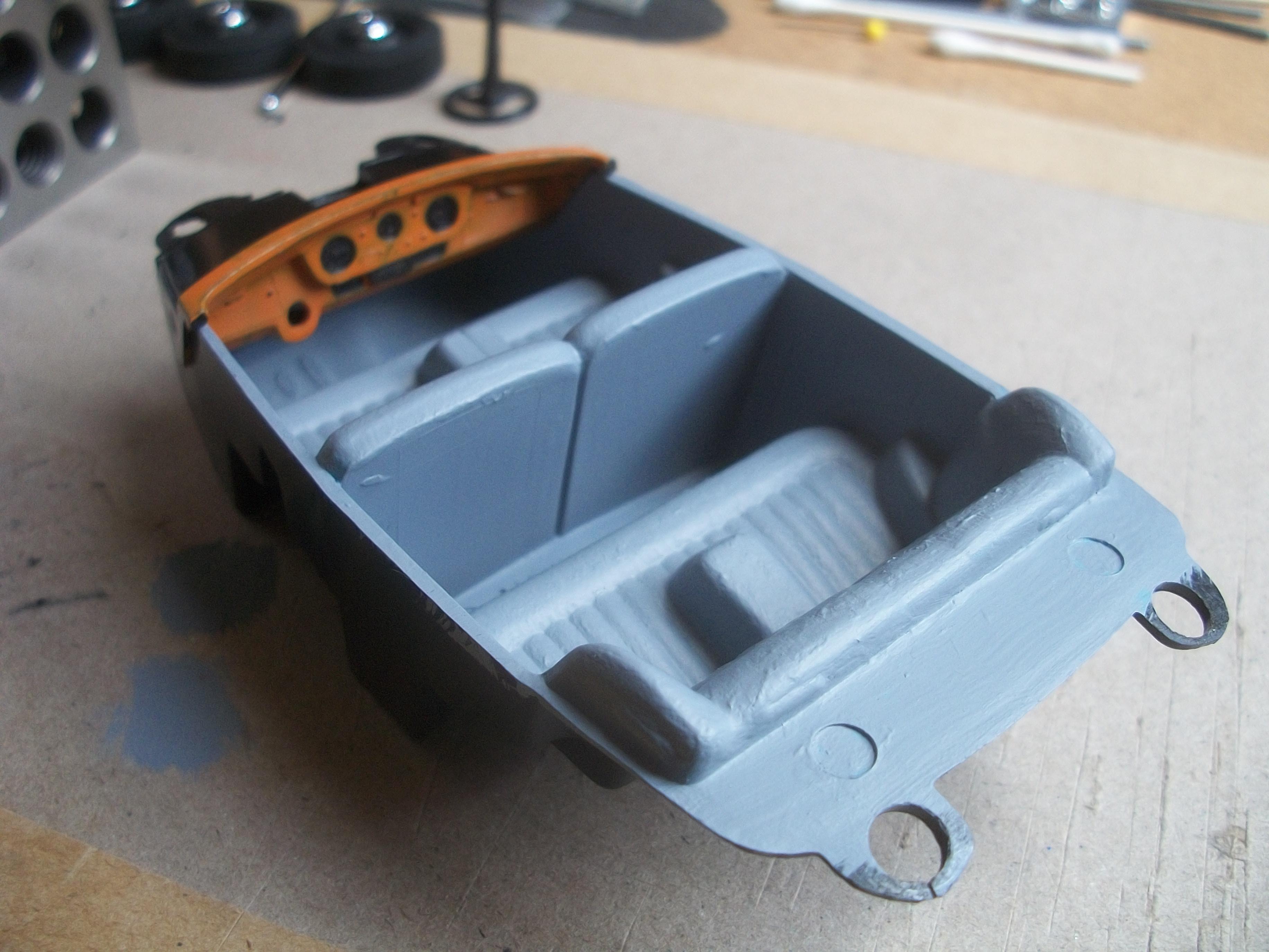
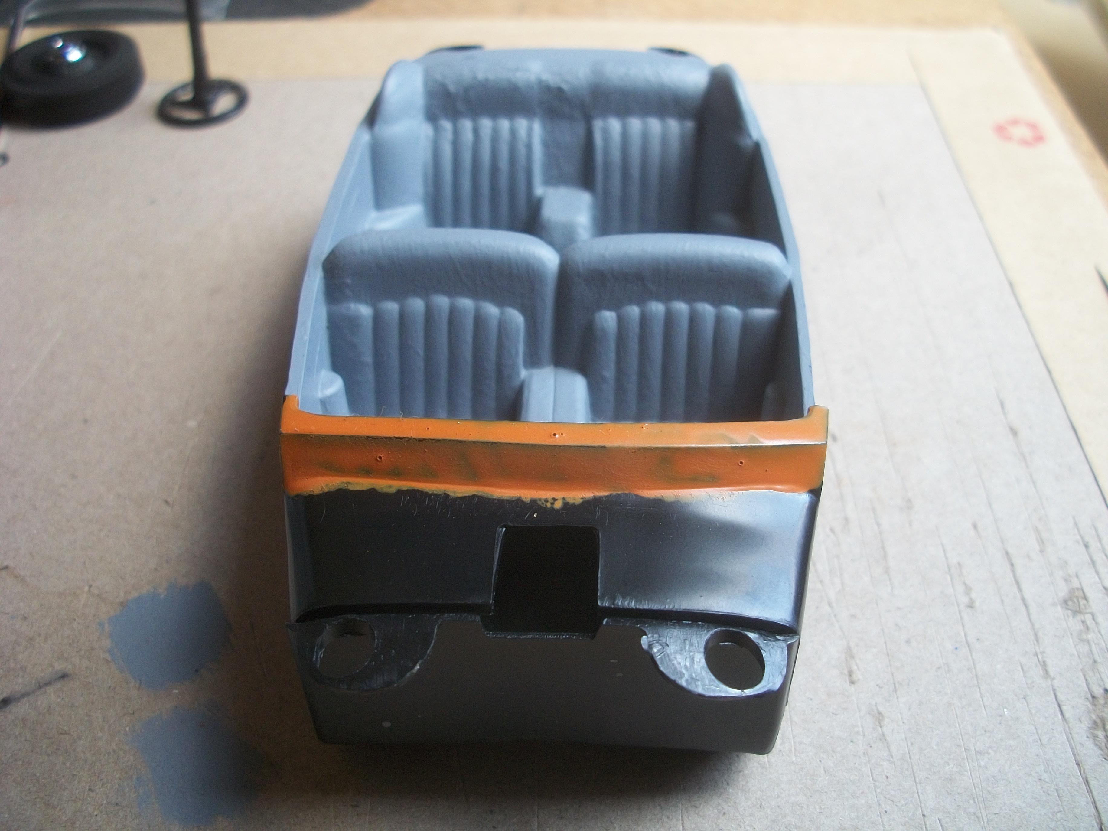
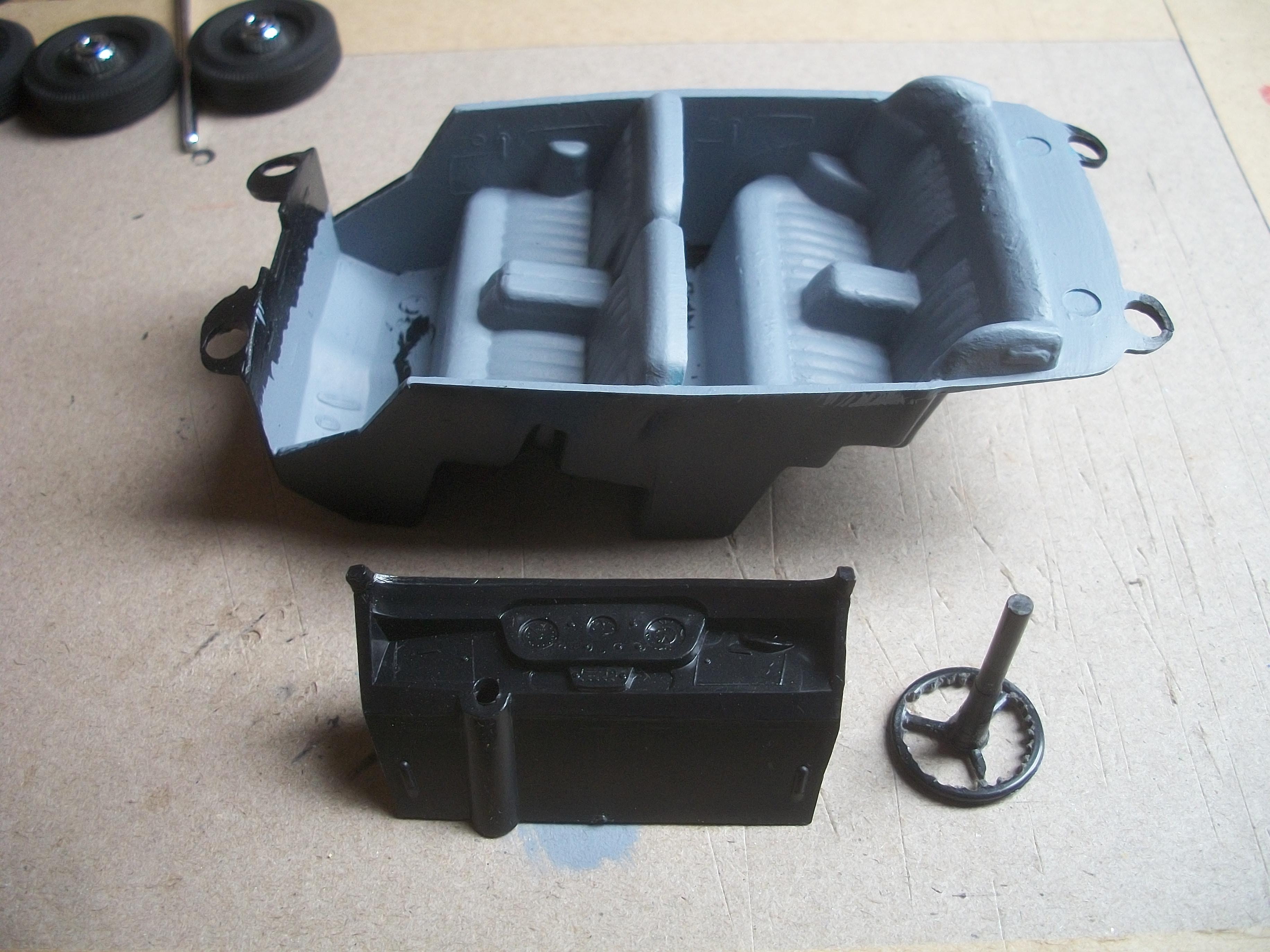
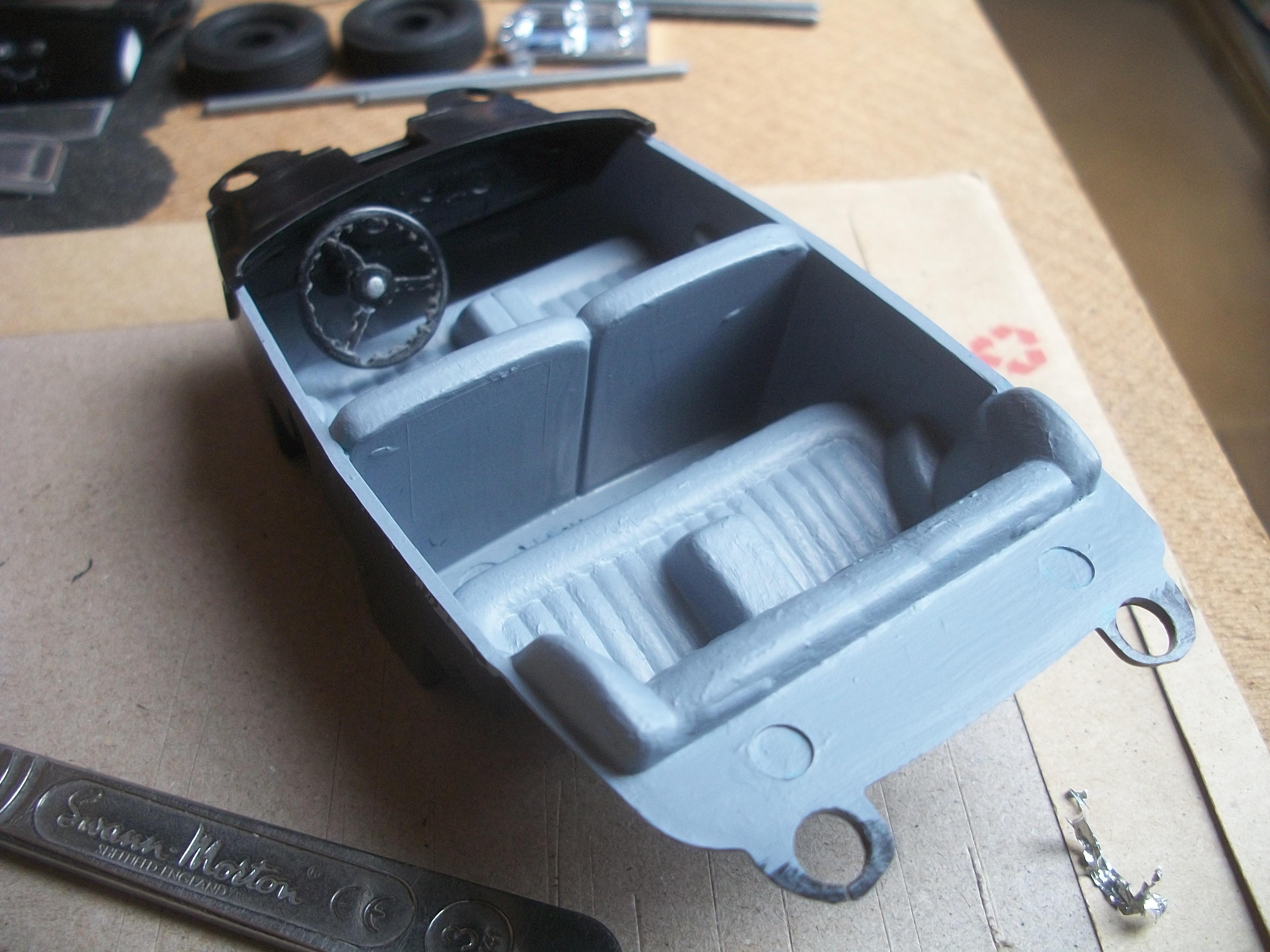
I managed to get a full refund for the faulty Sharpie set, and also I was able to purchase a replacement set of pens . . . It was time to set about changing this Silver Cloud dashboard from LHD to RHD, so I used my saw to remove the steering column support tube from the dashboard. Then I measured and cut out the location for the same support tube to slot into it's new position . . . I found that by using the narrow orange tape instead of glue this was sufficient to hold the steering column in place nice and firmly. Once the top half of the hole in the dashboard is enlarged slightly the steering wheel will not be touching the driver's seat . . . With the dashboard mounted into the interior seating tub, the orange tape and also the cut out on the left side of the dash are not visible. Using the fine pointed tip of a cocktail stick, I applied a tiny amount of Vallejo acrylic white paint to the detail on the speedometer gauge. The incredibly tiny control knobs on the dashboard were given a touch of silver Sharpie, using the new pen this time . . . David
-
Rolls-Royce No Chemicals, No Paint, No Harmful Glues
Anglia105E replied to Anglia105E's topic in WIP: Model Cars
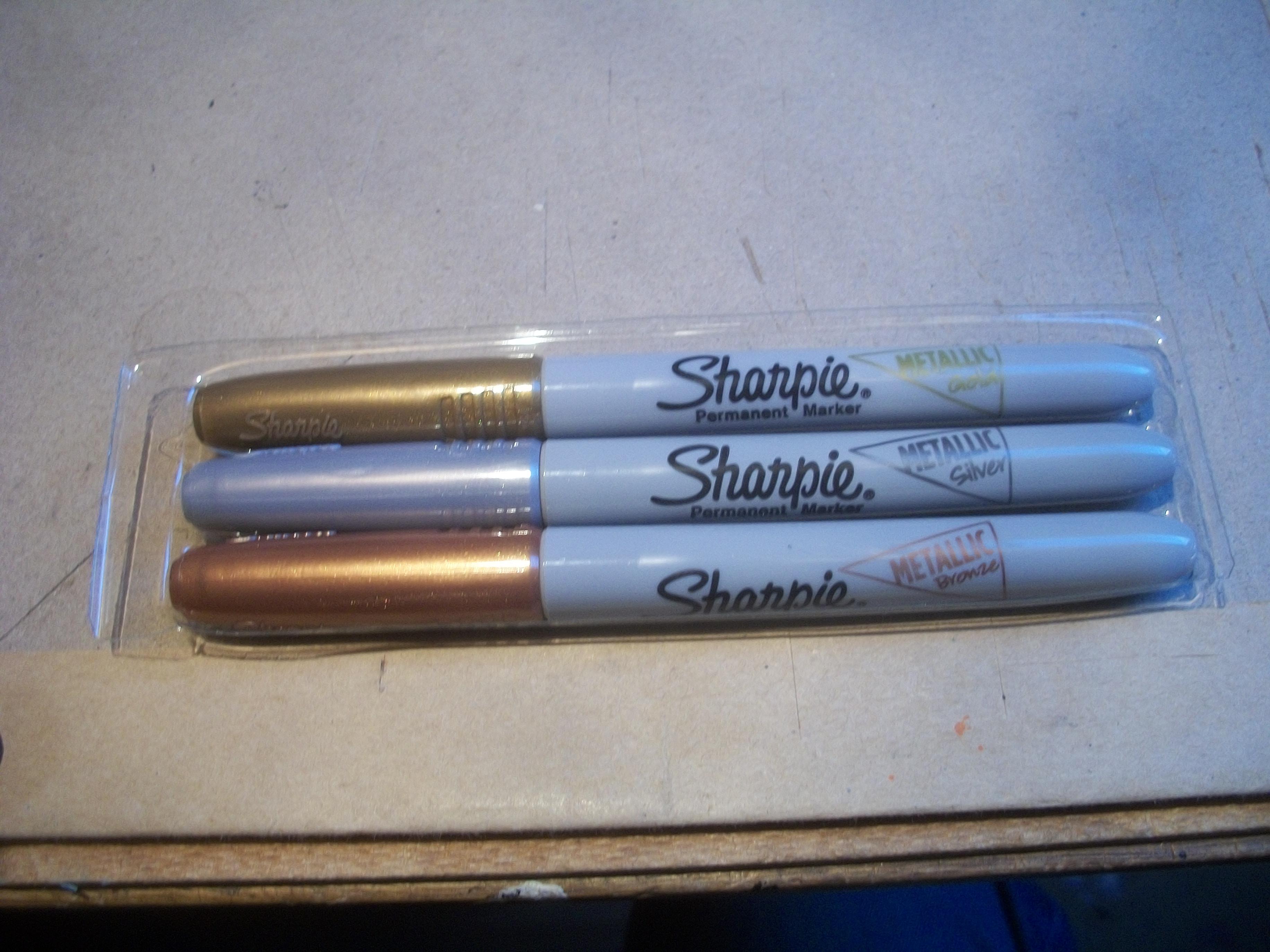
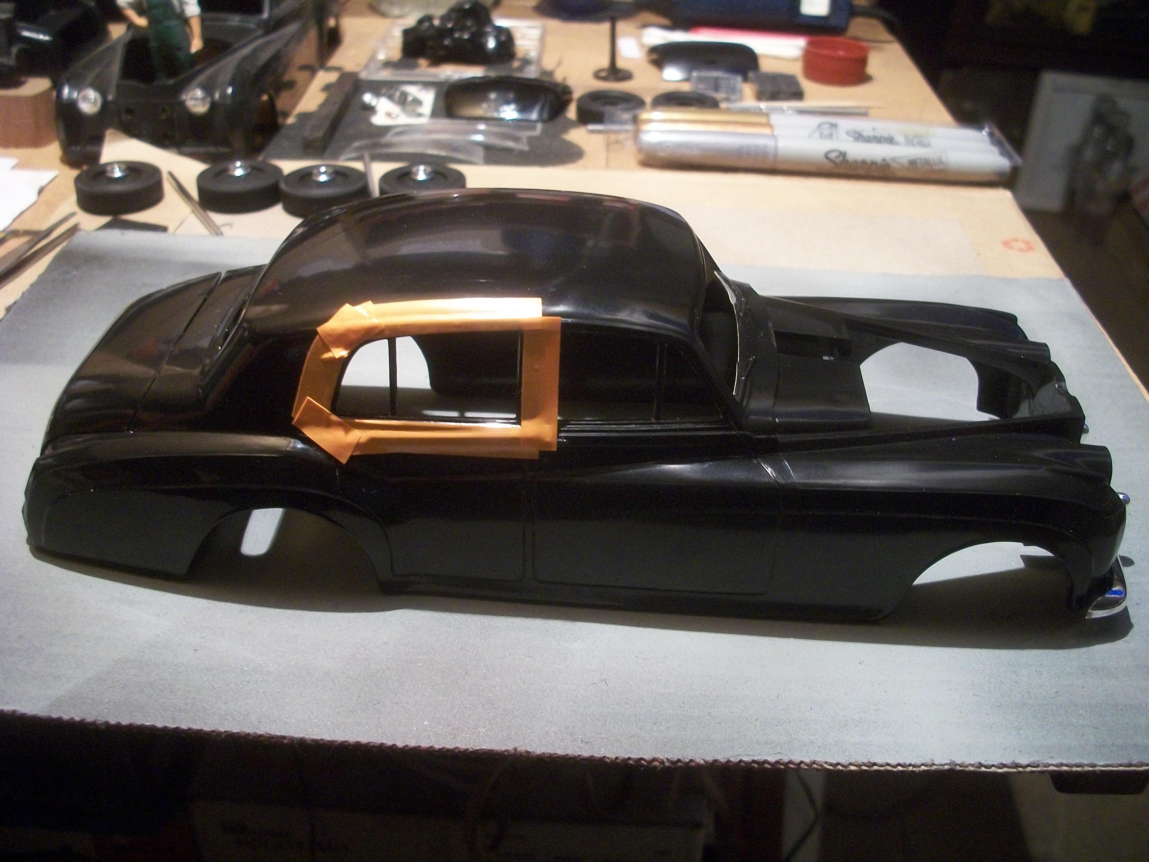
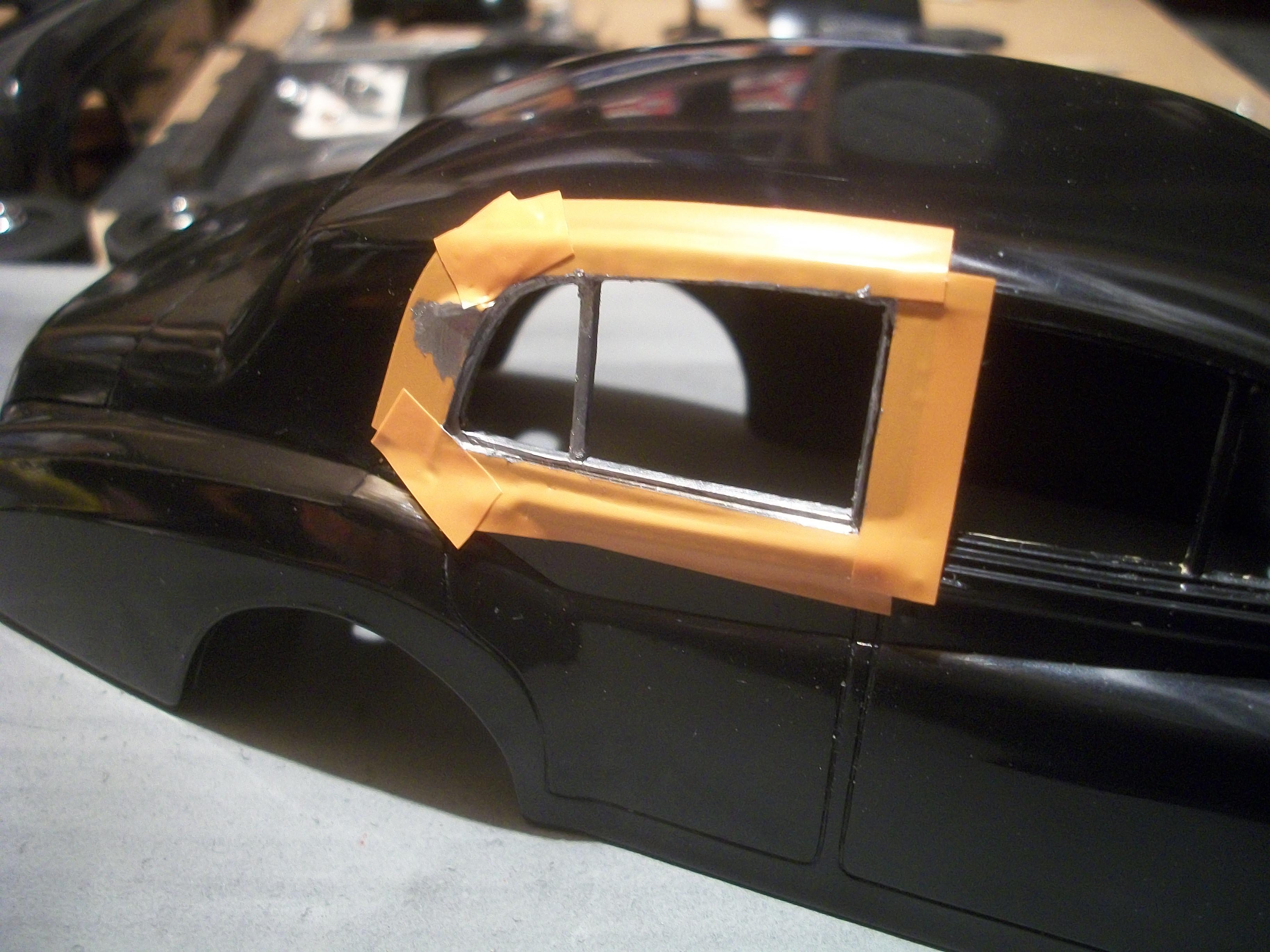
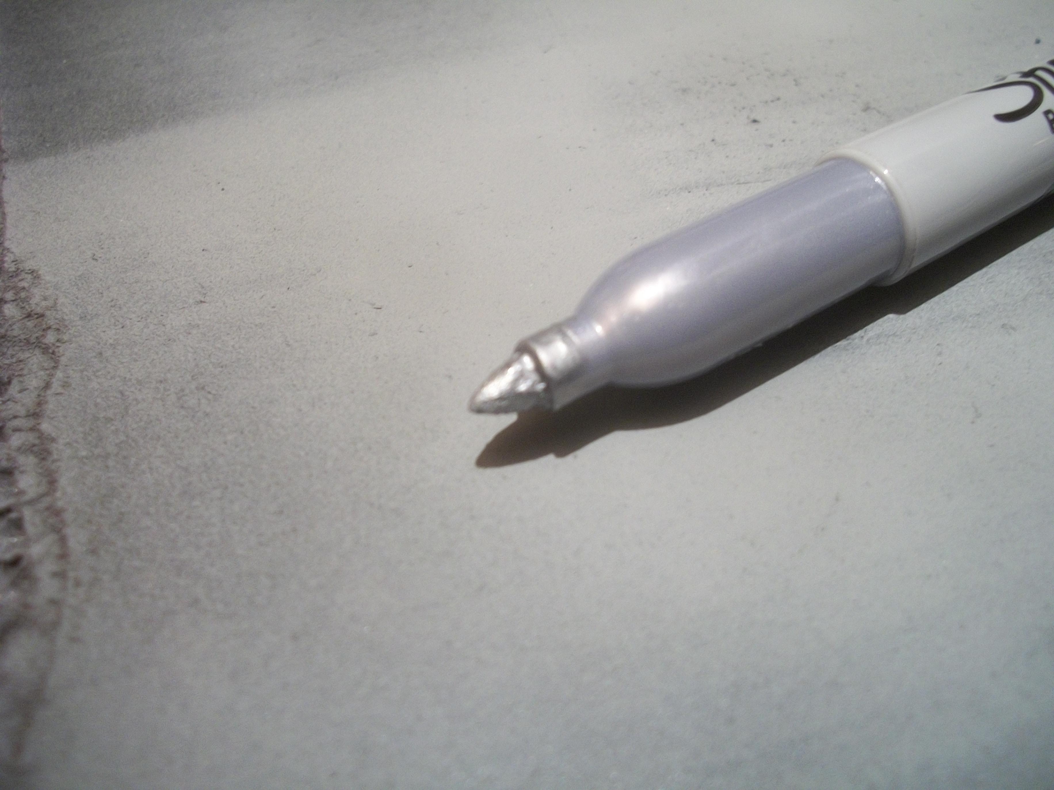
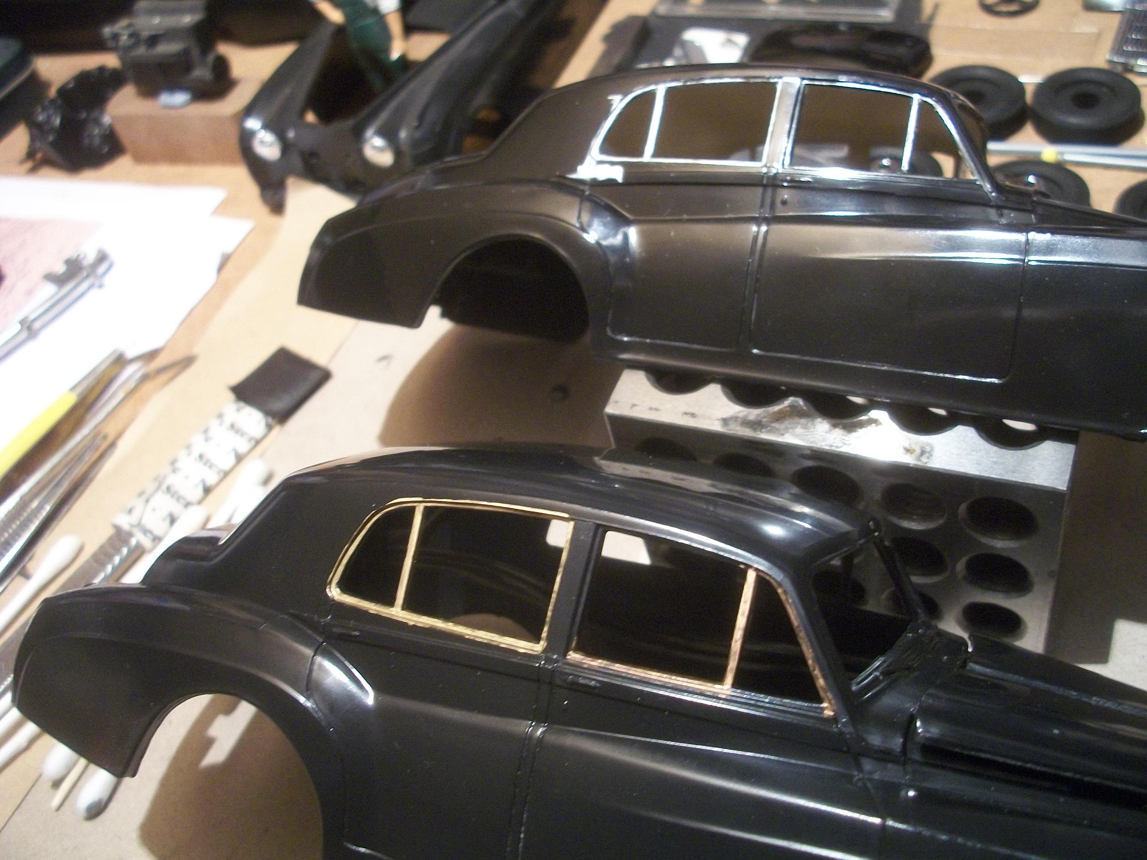
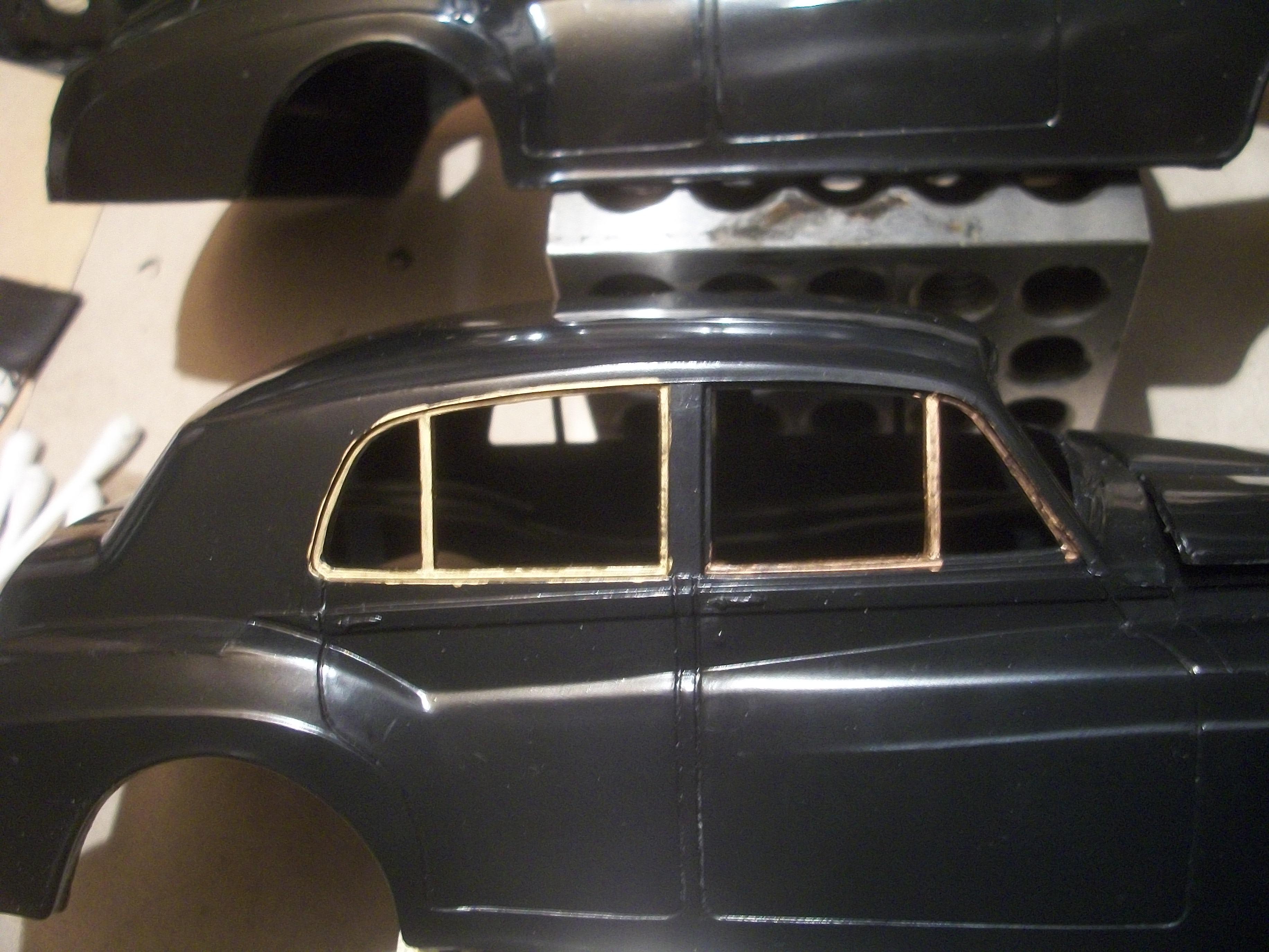
Earlier today I picked up a set of three metallic Sharpie marker pens, one Gold, one Bronze and one Silver . . . Working on the actual body shell for this build, I began to apply the Silver Sharpie to the driver's side rear window frame of the model. This was after I had masked off the surrounding area of the body shell with my narrow orange tape, because the Sharpie product is difficult to remove as it is permanent. To begin with, the Sharpie went on smoothly and with hardly any effort and no excessive pressure. Just when I was thinking this will look good, the fine point nib of the silver Sharpie began to leak badly. The almost chrome liquid ran along the frame of the door and collected in a blob. Fortunately, this was on the tape, and not on the surrounding body. I have never had any Sharpies do this to me during eight years of model building. The liquid is escaping from the nib and running down to the pointed tip, or at least it was for five minutes, and the the pen stopped working altogether. I did manage to coax a little bit of silver grey out onto a piece of card, but it was not possible to apply any silver Sharpie to the window frame of the model . . . As an experiment, I applied the gold Sharpie to the rear window frame of the test body, and there was no problem. Also, I repeated the process with the bronze Sharpie on the front window frame of the test body. Again, no problem . . . So it is only the silver Sharpie that is leaking. There isn't much point in me claiming that one of the three pens in the pack appears to be faulty by contacting the supplier, so does this mean that I have to contact the Sharpie company directly? My previous pack of three metallic Sharpies is probably around five years old, and both the gold and the bronze still work fine to this day. The silver pen ran out early in the first year, five years ago. I was wondering if any other MCM Forum members had experienced any problems with the silver Sharpie pens? David
-
Rolls-Royce No Chemicals, No Paint, No Harmful Glues
Anglia105E replied to Anglia105E's topic in WIP: Model Cars
Thanks for the information Mark, and here is a link to one that I found on Ebay here in the UK . . . https://www.ebay.co.uk/itm/316245272621?chn=ps&_ul=GB&var=614903943724&_trkparms=ispr%3D1&amdata=enc%3A1vVp9eJgrQcuKEBmQz9kw1g26&norover=1&mkevt=1&mkrid=710-134428-41853-0&mkcid=2&mkscid=101&itemid=614903943724_316245272621&targetid=2425733423477&device=c&mkt They don't seem to be at all expensive really, from what I have seen so far . . . David -
Rolls-Royce No Chemicals, No Paint, No Harmful Glues
Anglia105E replied to Anglia105E's topic in WIP: Model Cars
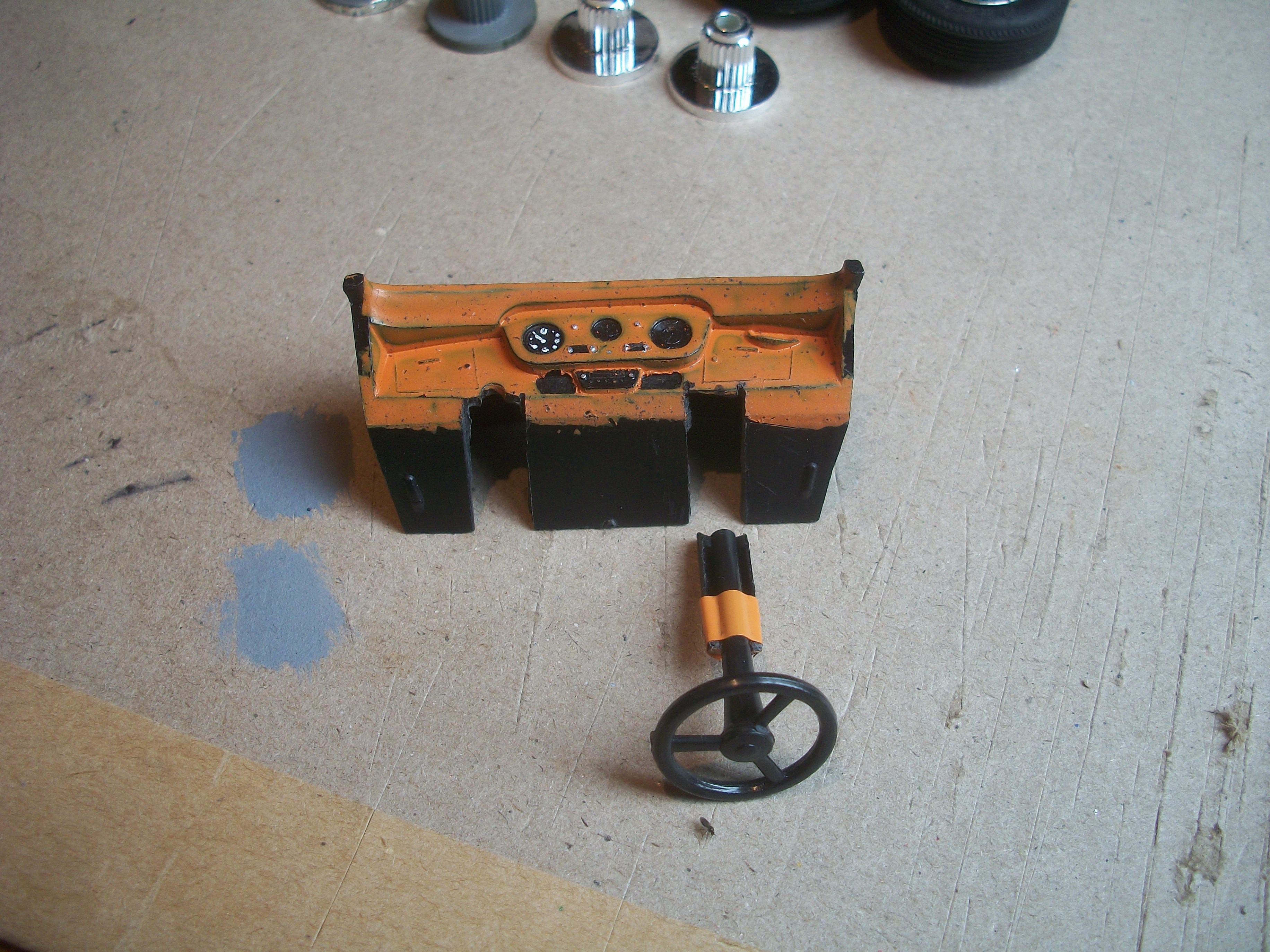
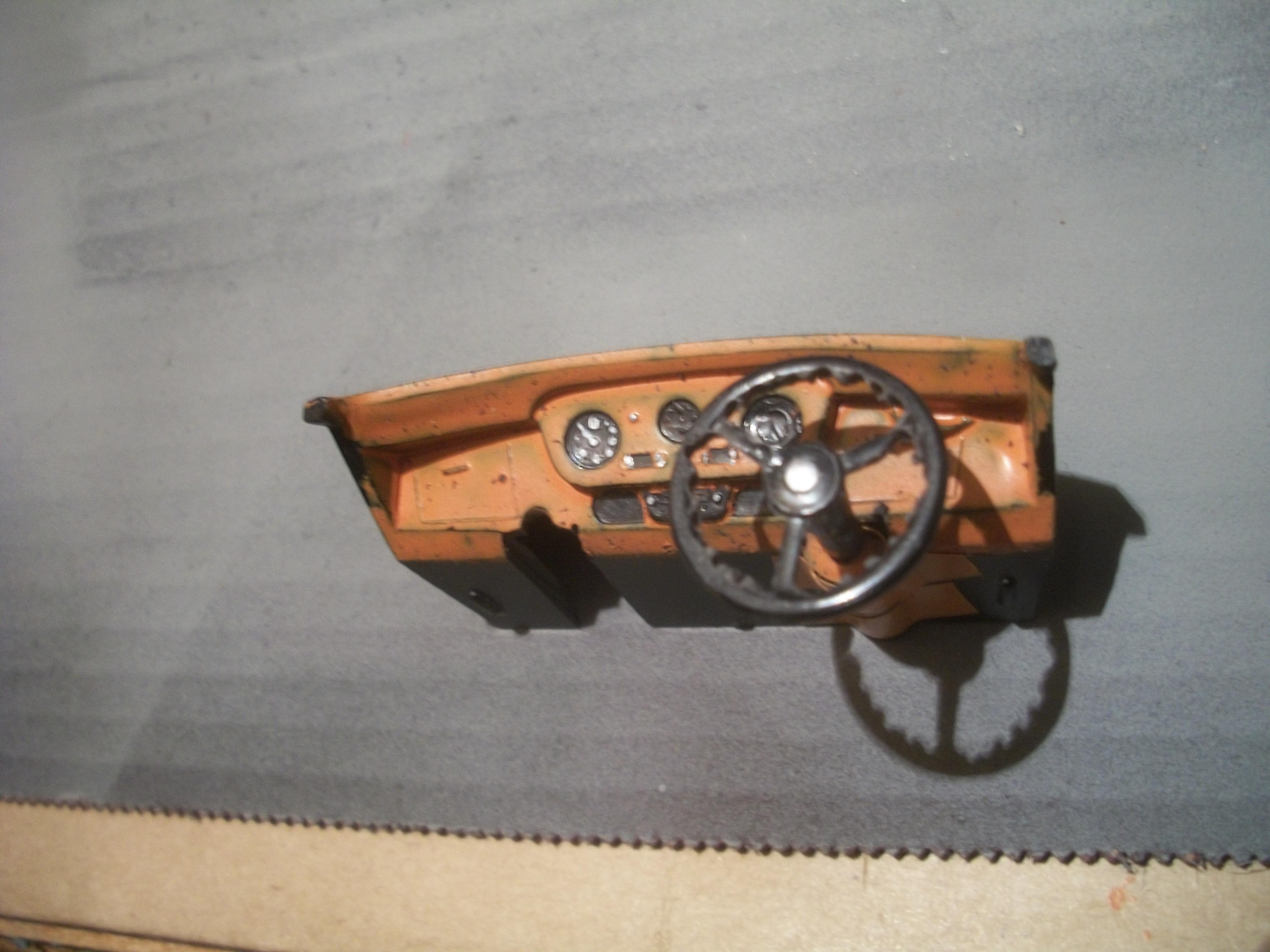
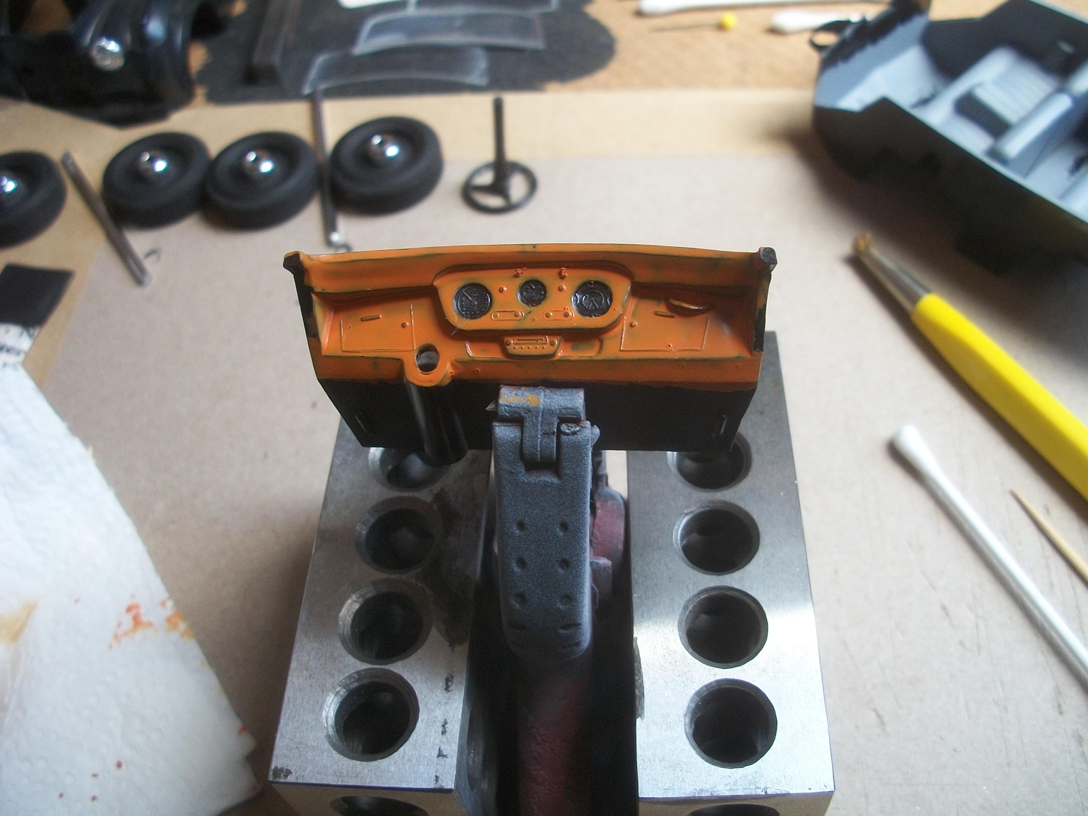
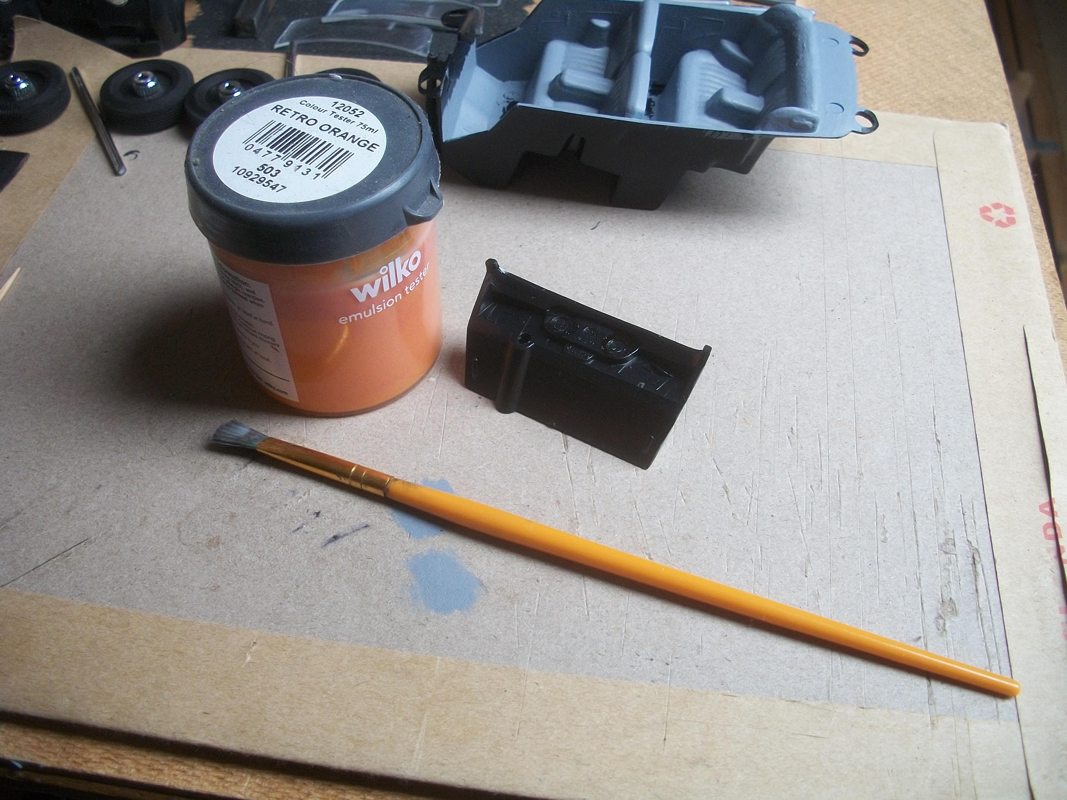
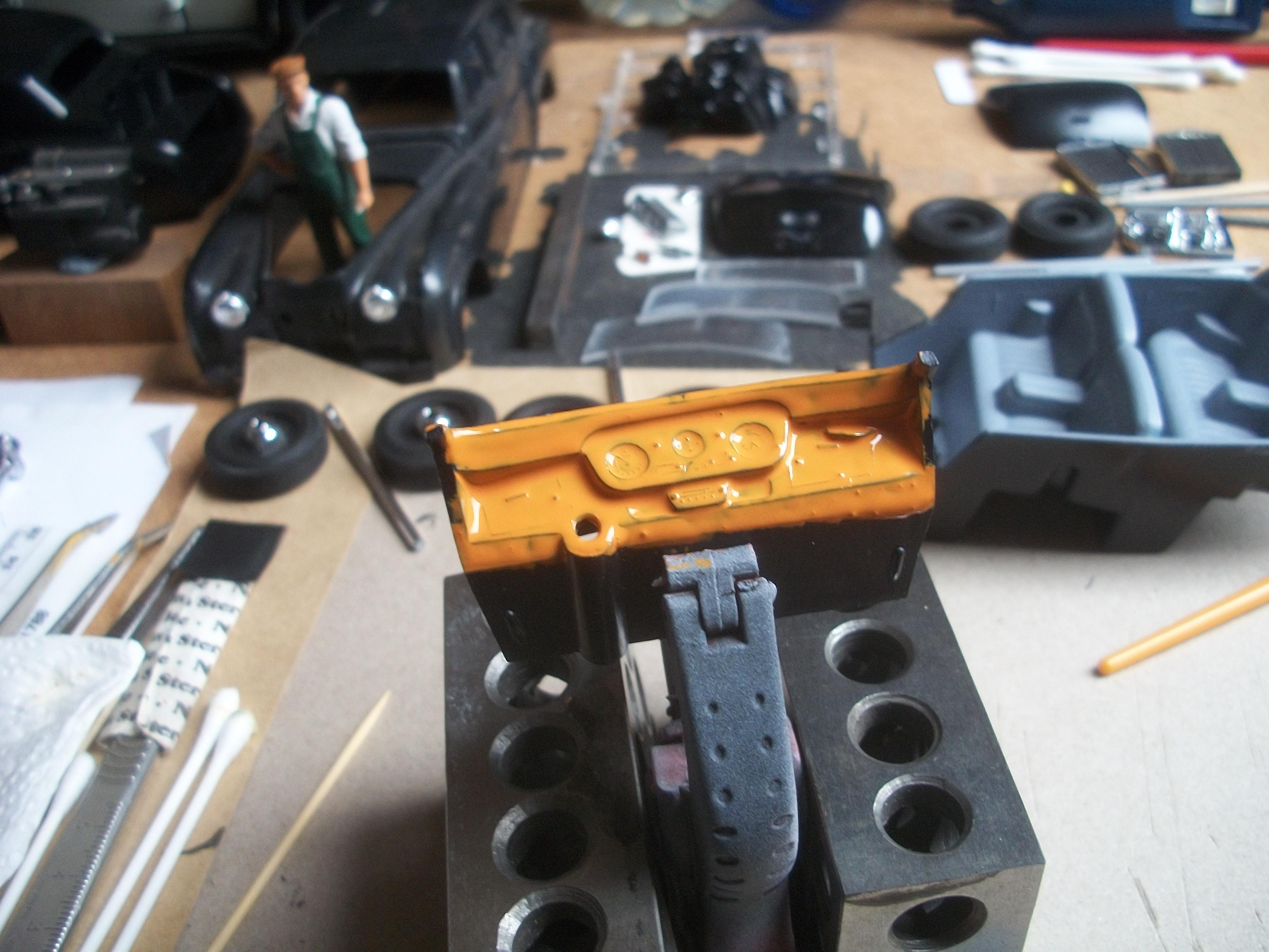
The Retro Orange emulsion paint by WILKO was still slightly tacky after 20 hours drying overnight, which is surprising for emulsion paint in my experience. This did not matter too much really, because I intended to scratch the surface of the paint anyway for this dashboard. The gauges of the dashboard and a few other areas were scraped clean of orange paint, to allow the black plastic to show through, using the pointed tip of a cocktail stick . . . Then I used a brass bristled brush to stipple the surface of the paint quite firmly, so as to create a burr walnut effect . . . So far, the dashboard looks pretty good and I shall add white acrylic detail for the gauges, also applied with the tip of the cocktail stick and not a brush. David
-
Rolls-Royce No Chemicals, No Paint, No Harmful Glues
Anglia105E replied to Anglia105E's topic in WIP: Model Cars
Your advice is all good Mark, and from what you say, it sounds like the environment in which you live is even more harsh than I thought mine was. My feeling regarding the model car building is that without this absorbing hobby I would be incredibly bored, and probably not quite sane ! . . . You have made me think seriously about plug in air filters for the house, so I must look into that requirement in terms of cost and availability. I have never seen such filters advertised here in the UK, but then again I wasn't searching for them to be honest . . . At the moment I am staying away from enamel paints, acrylic paints, aerosol cans and airbrushing. The only paints that I am prepared to use are water based emulsion paints and the Vallejo brush on acrylics. This Rolls-Royce Silver Cloud build is my first ever to use polished plastic body parts, washable PVA glue (child friendly) and also using a drilling and pinning method instead of super glue to attach parts. The Revell Contacta Professional glue is a very good product, for example, but the smell is almost overpowering. The strong smell of Humbrol Enamel Thinners that I would have used for brush cleaning only was guaranteed to trigger an immediate violent response from my wife, even though I am two floors upstairs from her in the loft and with the roof window open too . . . David -
Rolls-Royce No Chemicals, No Paint, No Harmful Glues
Anglia105E replied to Anglia105E's topic in WIP: Model Cars
White vinegar spray is what is needed then Les ! Thanks . . . David -
Rolls-Royce No Chemicals, No Paint, No Harmful Glues
Anglia105E replied to Anglia105E's topic in WIP: Model Cars
You have a good point there about the mold and fungus Jose . . . I believe it is quite possible there may be evidence of mold or fungus in at least one of the rooms in our cottage. The property was built in 1886, so it is around 140 years old, and the stone walls are 18 inches in thickness . . . We don't have air conditioning. I am not sure how I would deal with the mold and fungus issue ? David -
Rolls-Royce No Chemicals, No Paint, No Harmful Glues
Anglia105E replied to Anglia105E's topic in WIP: Model Cars
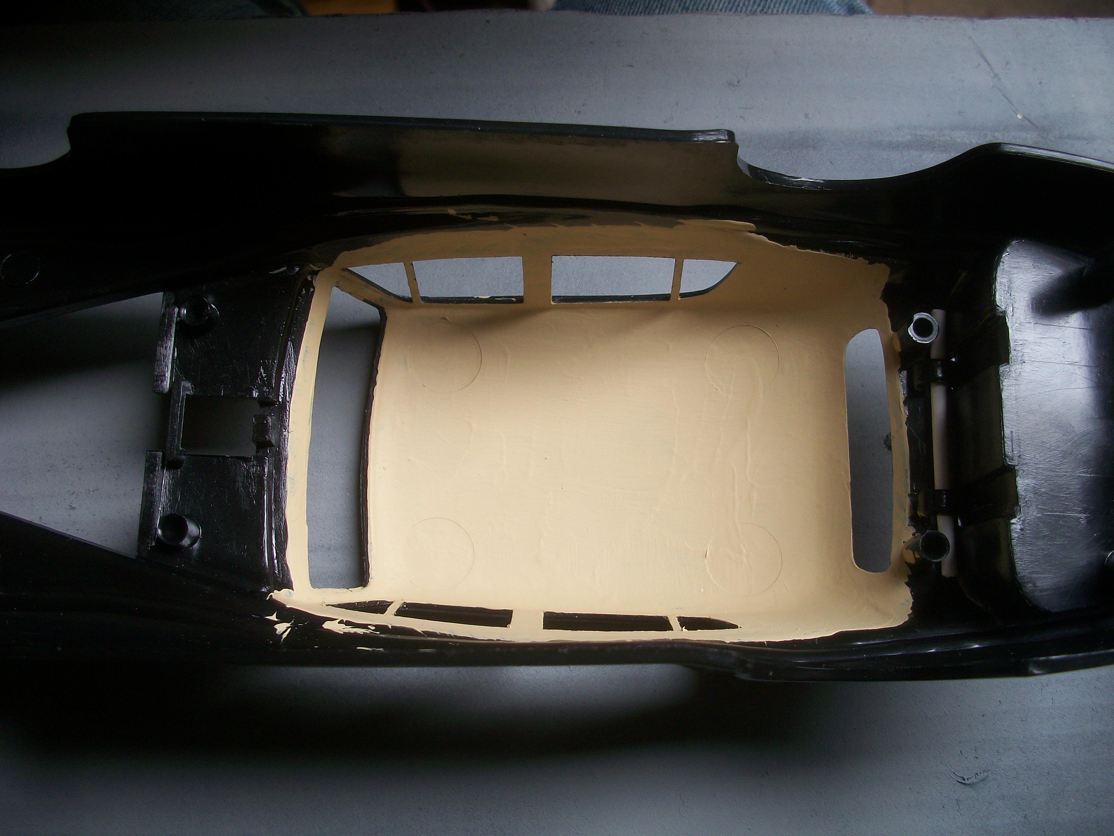
The headlining has turned out nicely, now that two coats of the emulsion have been applied . . . I tried out the orange Sharpie on the black plastic of the dashboard, and as expected this did not work. After considering other options, I found some old WILKO emulsion paint, which is ' Retro Orange ' in a small tester pot . . . This has been applied onto the dashboard area that needs to be a burr walnut finish. So far this is just one coat drying overnight, and I shall experiment with a brass bristled brush tomorrow. The idea is to scratch the surface of the orange emulsion paint and thus allow the black to show through. Additionally, I could apply some black acrylic paint or dark brown emulsion with the same brass bristled brush . . . David
-
Rolls-Royce No Chemicals, No Paint, No Harmful Glues
Anglia105E replied to Anglia105E's topic in WIP: Model Cars
It is a shame that all those wonderful products usually contain at least one harmful ingredient of varying amounts, and very often several. To a certain extent, my lung condition may have been caused due to me not observing fully the safety precautions, such as insufficient ventilation in the workspace, perhaps not using a mask of high enough specification, not always wearing disposable latex gloves, and maybe not reading the labels on the backs of containers properly, although I thought I did . . . This is something that has been building up over a period of 8 years I would say. The odd thing is this . . . When I am at home in Derbyshire, specifically inside my stone built cottage, I am experiencing shortage of breath, coughing, bringing up phlegm during the first half of every day, loss of appetite and energy, muscle wastage and difficulty sleeping, as well as other unpleasant symptoms. The busy road immediately outside our cottage carries daily traffic of HGV's that collect and deliver stone products to and from large local quarries, so there is an excessive amount of dust in the air, much of which is brake dust from the overheating brake drums as the trucks descend the very long steep hill . . . Then, when I travel to Falmouth in Cornwall, always during the month of May every year, for my annual two weeks holiday I feel completely fine . . . No bad symptoms or illness whatsoever. Within two days of arriving back home, all of my symptoms return with a vengeance . . . How odd ? The air near the coast in Falmouth is so clean and pure, whereas my once beautiful countryside village has been contaminated it seems. David -
Rolls-Royce No Chemicals, No Paint, No Harmful Glues
Anglia105E replied to Anglia105E's topic in WIP: Model Cars
Of course Jose . . . Only the best for this build. David -
Rolls-Royce No Chemicals, No Paint, No Harmful Glues
Anglia105E replied to Anglia105E's topic in WIP: Model Cars
Okay thanks Mark . . . No problem ! ( enjoy the forum ) -
Rolls-Royce No Chemicals, No Paint, No Harmful Glues
Anglia105E replied to Anglia105E's topic in WIP: Model Cars
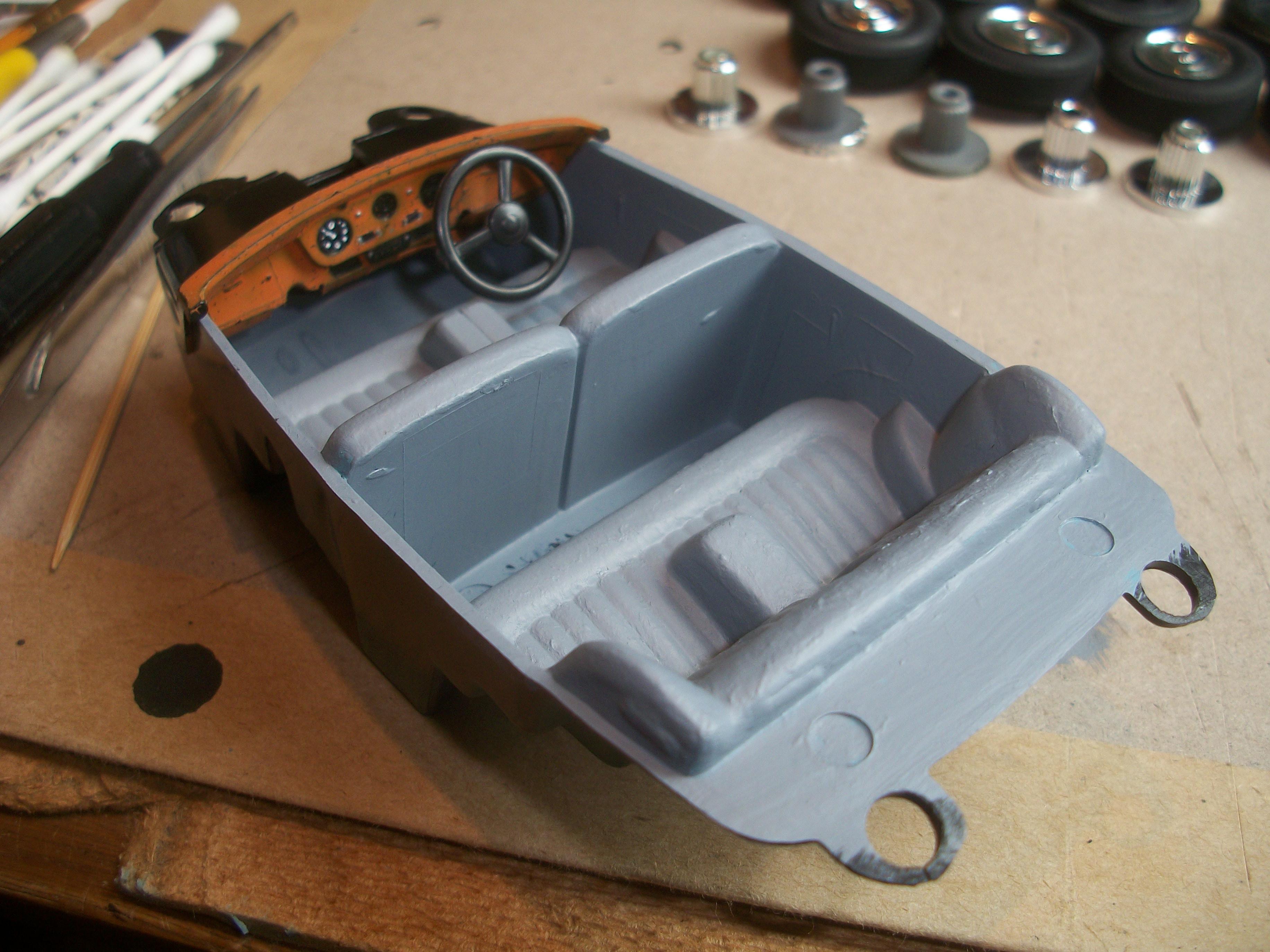
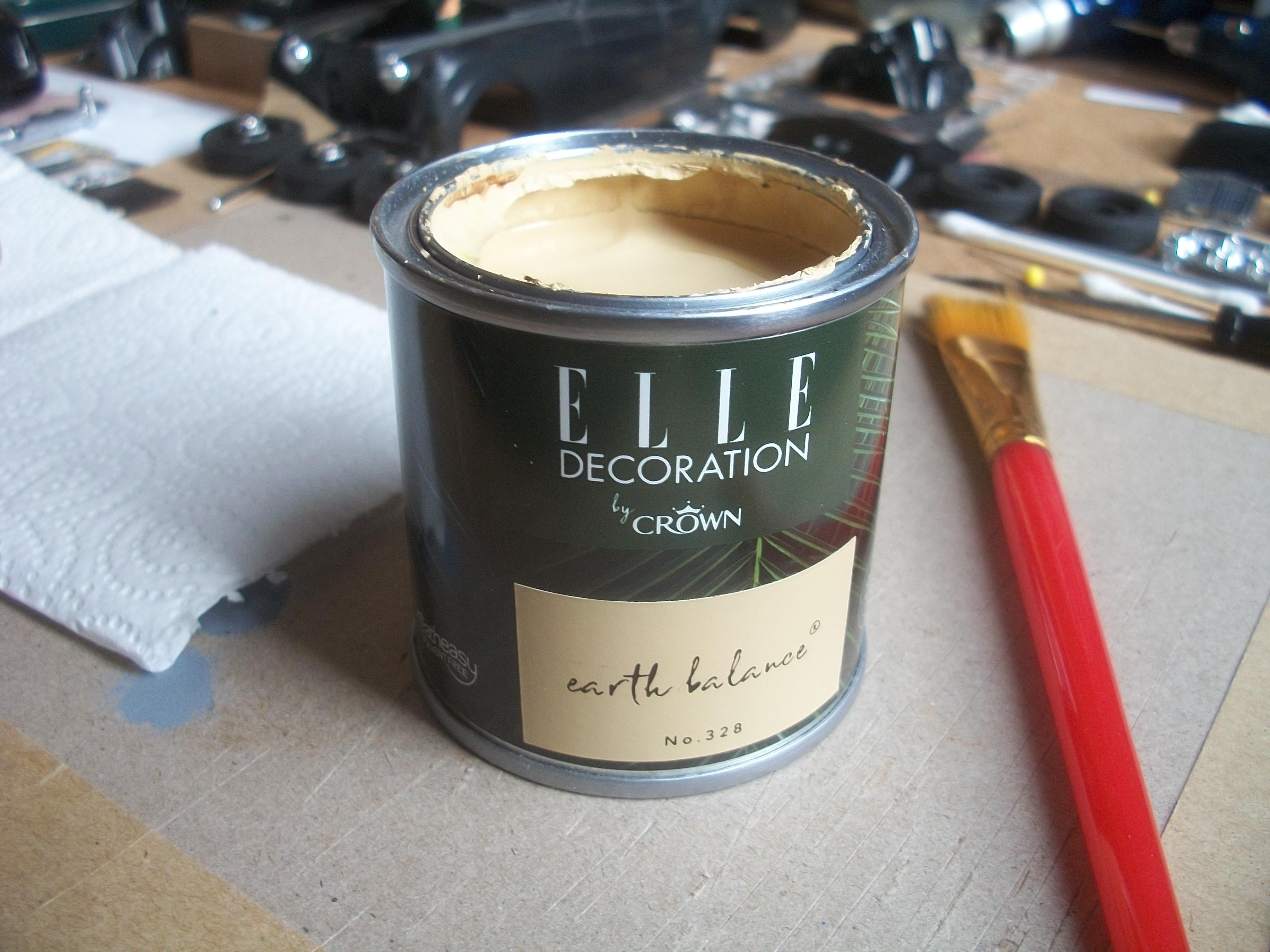
Earlier today I tried out some BMF on a section of the door window frame, but the result was not good . . . I am pretty sure that the three packs of BMF are rather old, so the foil is not sticking to the plastic. Usually, I can apply BMF easily, but this time it was a struggle. My regular suppliers of BMF here in the UK either have no stock, or the price has increased quite a lot . . . Having watched a YouTube video by a model builder in the US, in which he demonstrates how to use basic cheap kitchen foil as an alternative to BMF, my plan is to try out this method. The thin aluminium foil is applied over washable PVA glue, in just the same way as you would apply the genuine BMF. Next up was the headlining for the inside of the roof, within the passenger compartment. I have used Elle by Crown ' Earth Balance ' which is a water based emulsion paint. One coat of this paint has covered the black plastic quite well, but a second coat will be required. I am still getting used to the idea of working without applying a primer coat before the top coat, as I cannot use a grey primer from spray can, neither enamel nor acrylic . . . The dashboard was test fitted to the interior tub, along with the steering wheel and steering column. This is the LHD version, which I shall change to the RHD version for a British registered car . . . Usually, I would use enamel paints for the burr walnut finish of this dashboard, so for this build I shall be using Sharpies. David
-
Rolls-Royce No Chemicals, No Paint, No Harmful Glues
Anglia105E replied to Anglia105E's topic in WIP: Model Cars
Hi Mark . . . David here ( Anglia105E ), Please could you communicate with Pierre Rivard on his topic about the Ferrari, as this is my topic about my Rolls-Royce build . . . The Ferrari model that Pierre has built looks very good, but please do not hold your discussion on my thread, thank you . . . David Watson -
Rolls-Royce No Chemicals, No Paint, No Harmful Glues
Anglia105E replied to Anglia105E's topic in WIP: Model Cars
Thank you kindly Don . . . I am fairly confident that I can continue to build scale model cars, especially Rolls-Royce motor cars, as long as I follow my doctor's expert advice not to use solvent and toxic based chemical substances . . . I am surprised how washable PVA glue is holding styrene parts firmly, which I hadn't expected to work. David -
Rolls-Royce No Chemicals, No Paint, No Harmful Glues
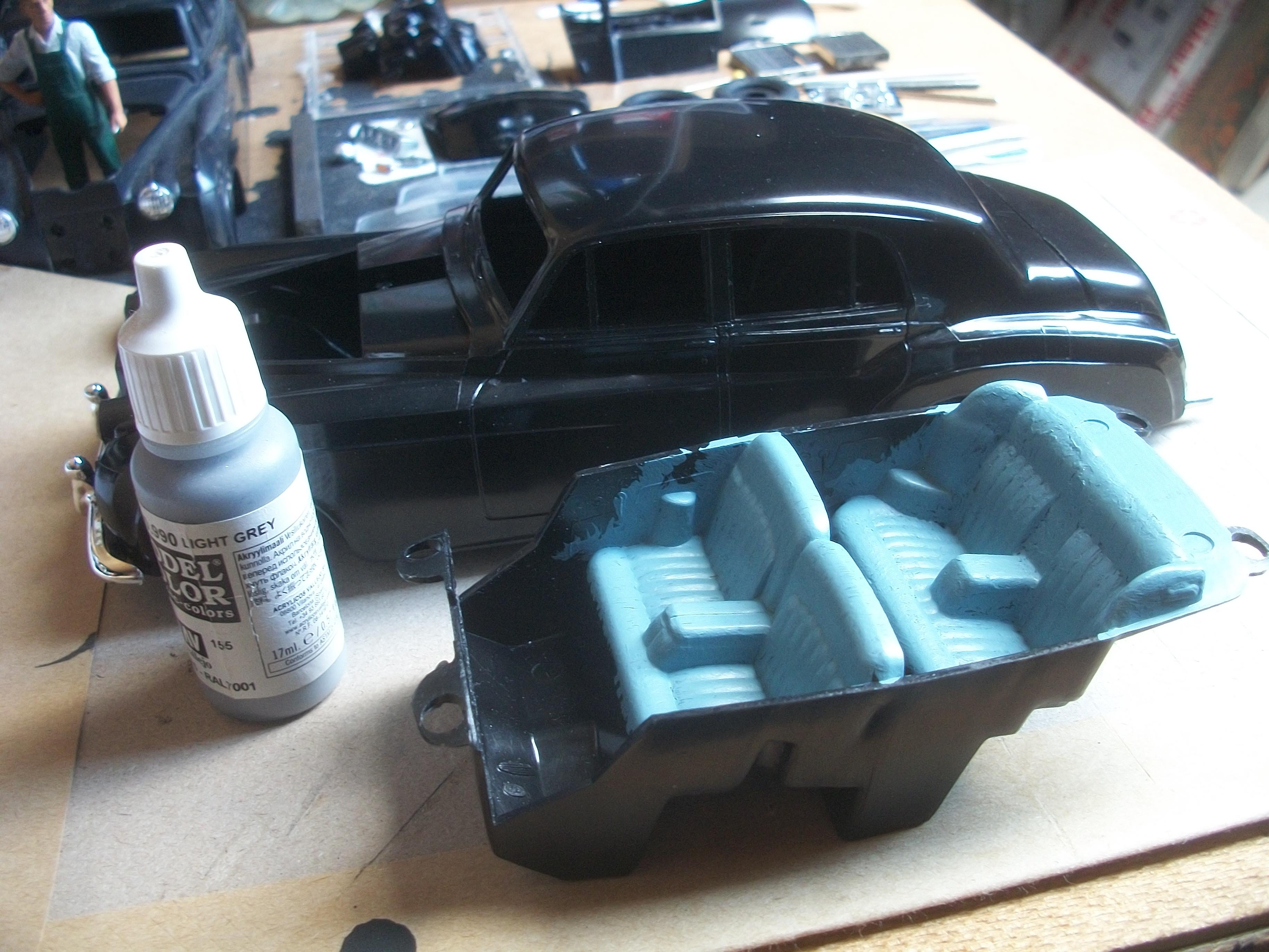
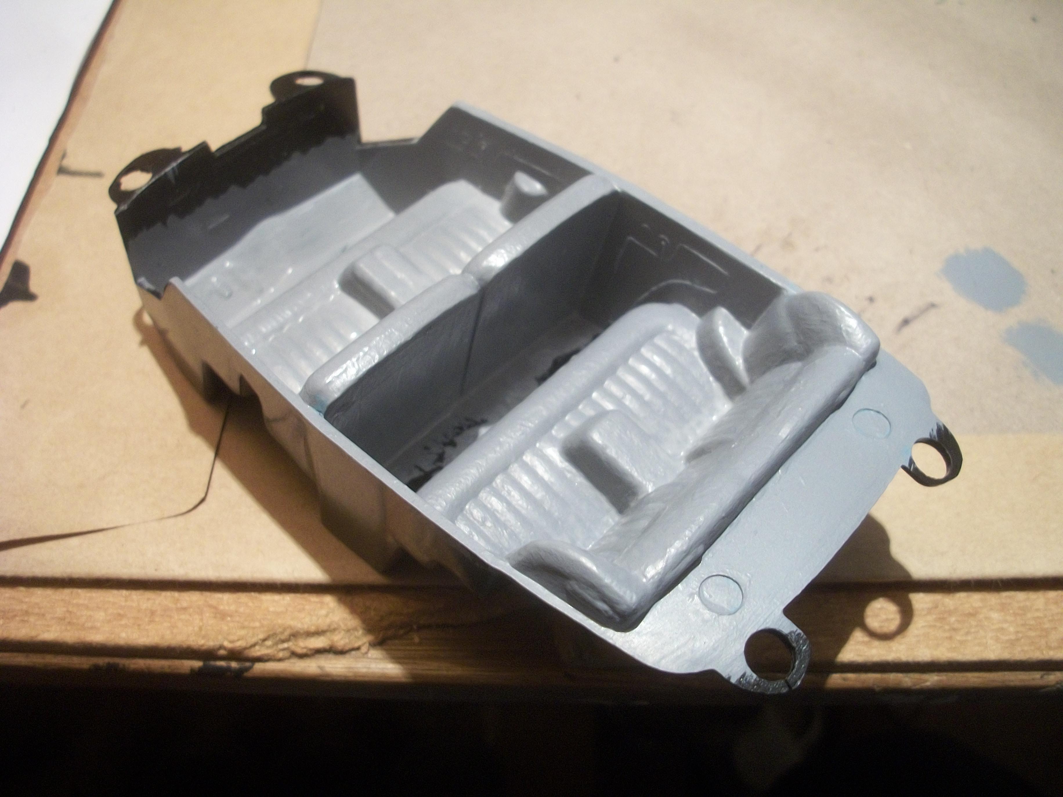
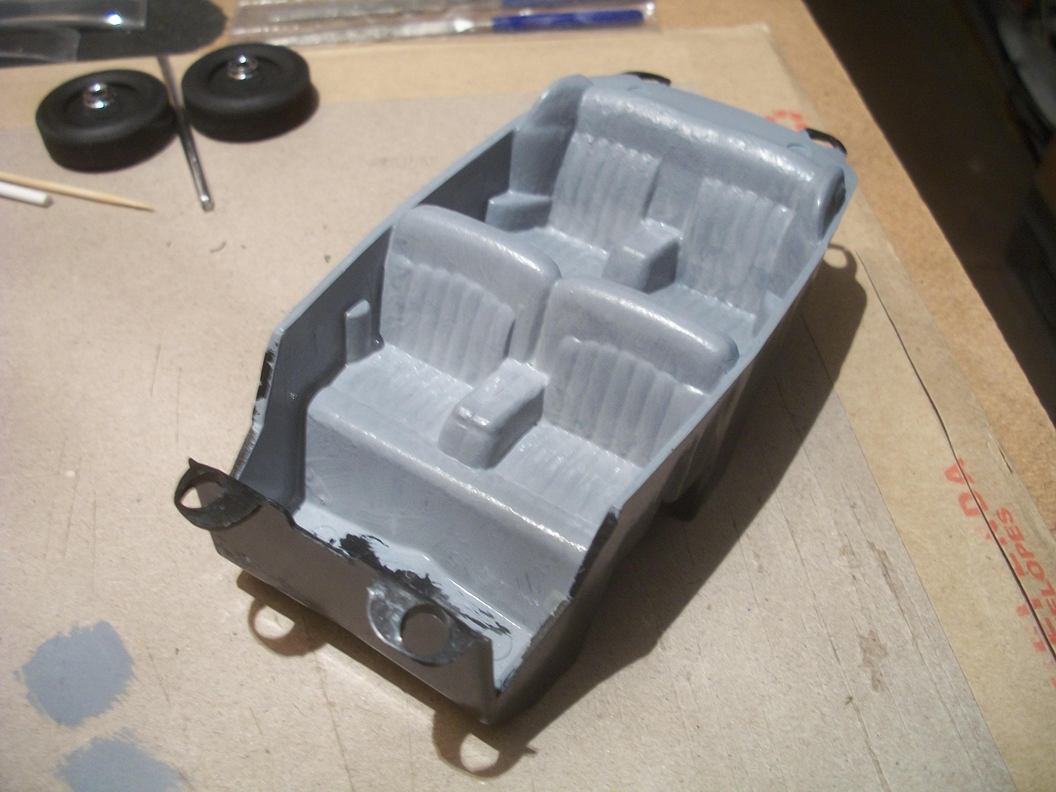
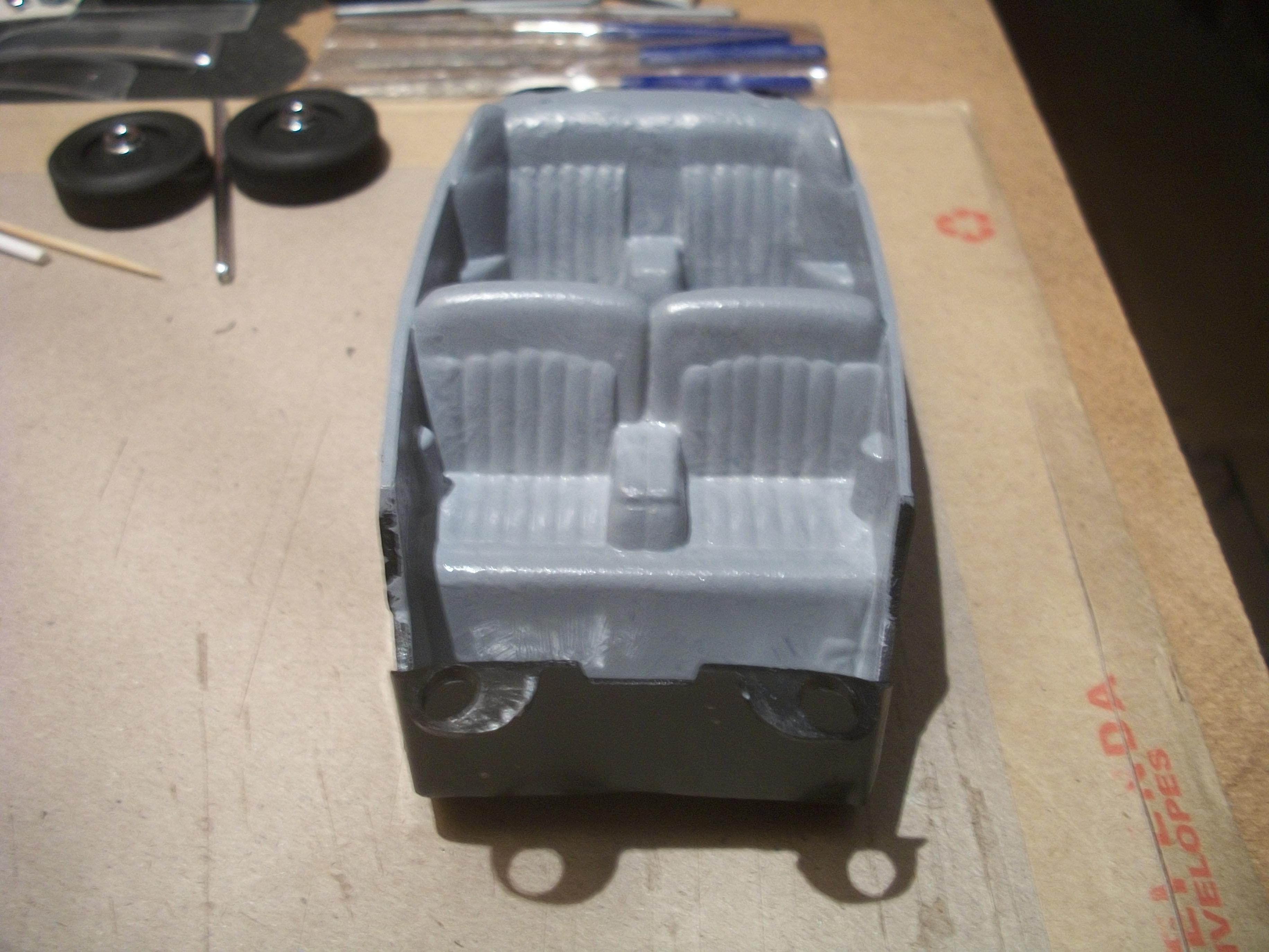
Anglia105E replied to Anglia105E's topic in WIP: Model Cars
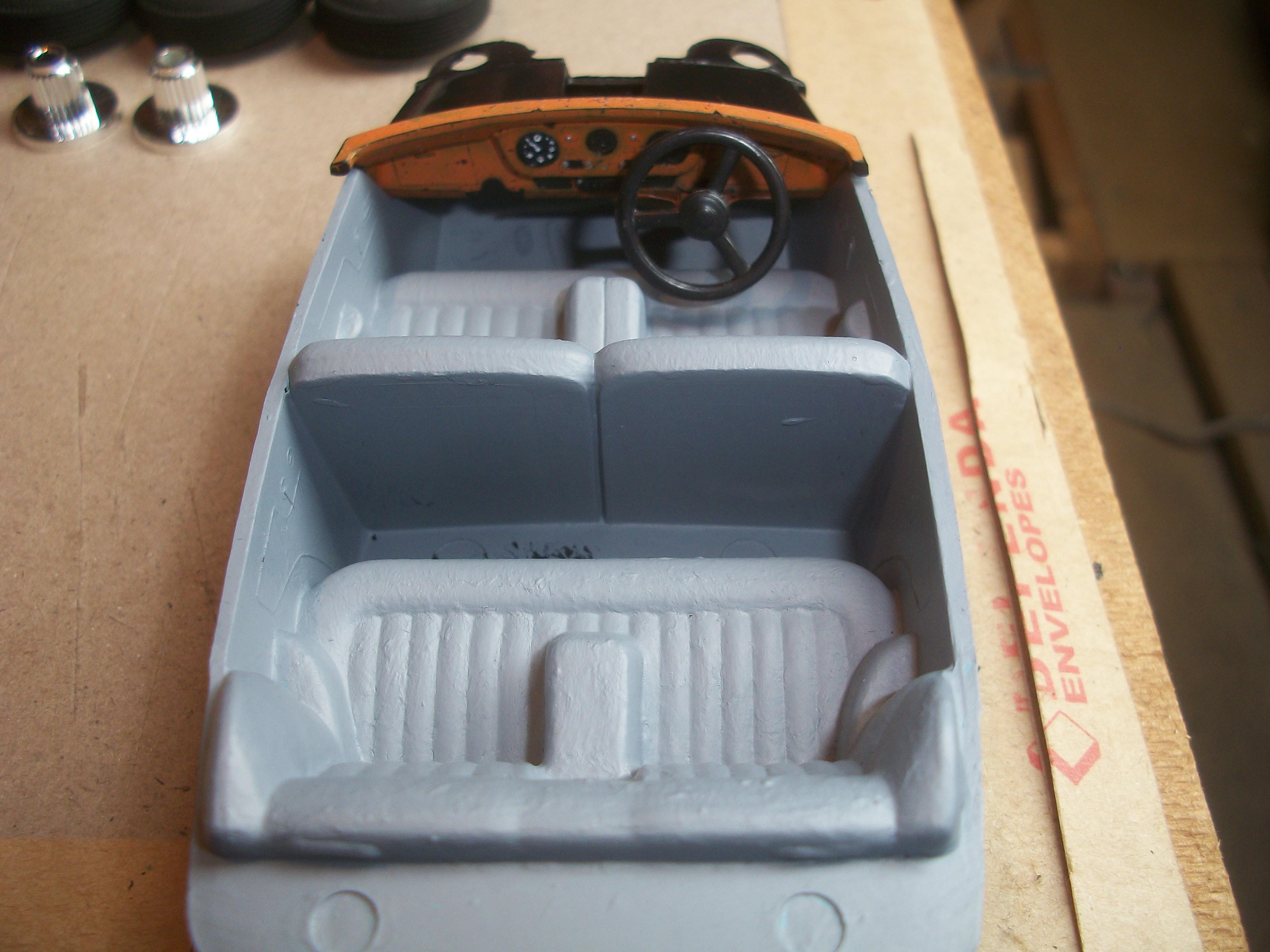
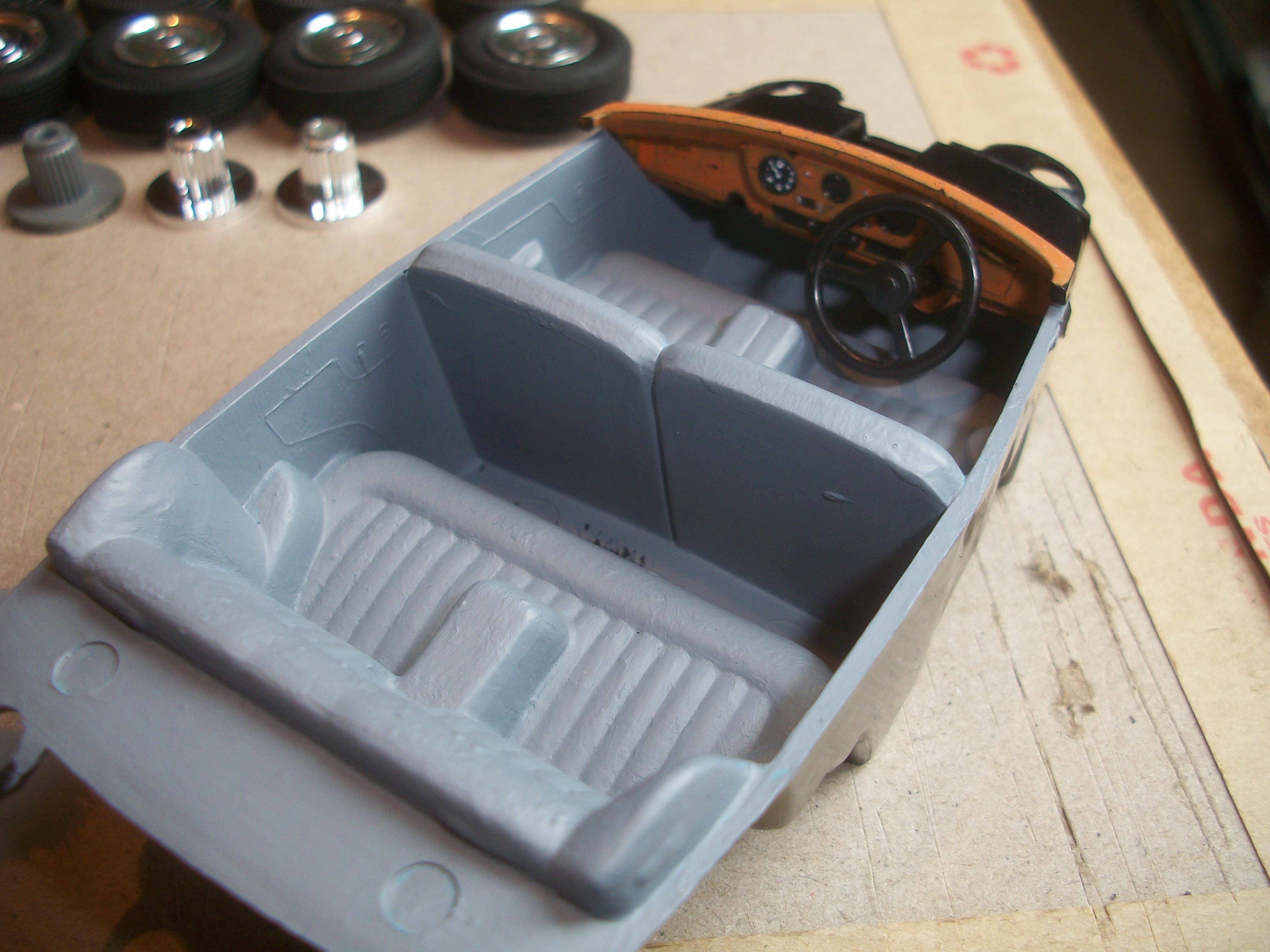
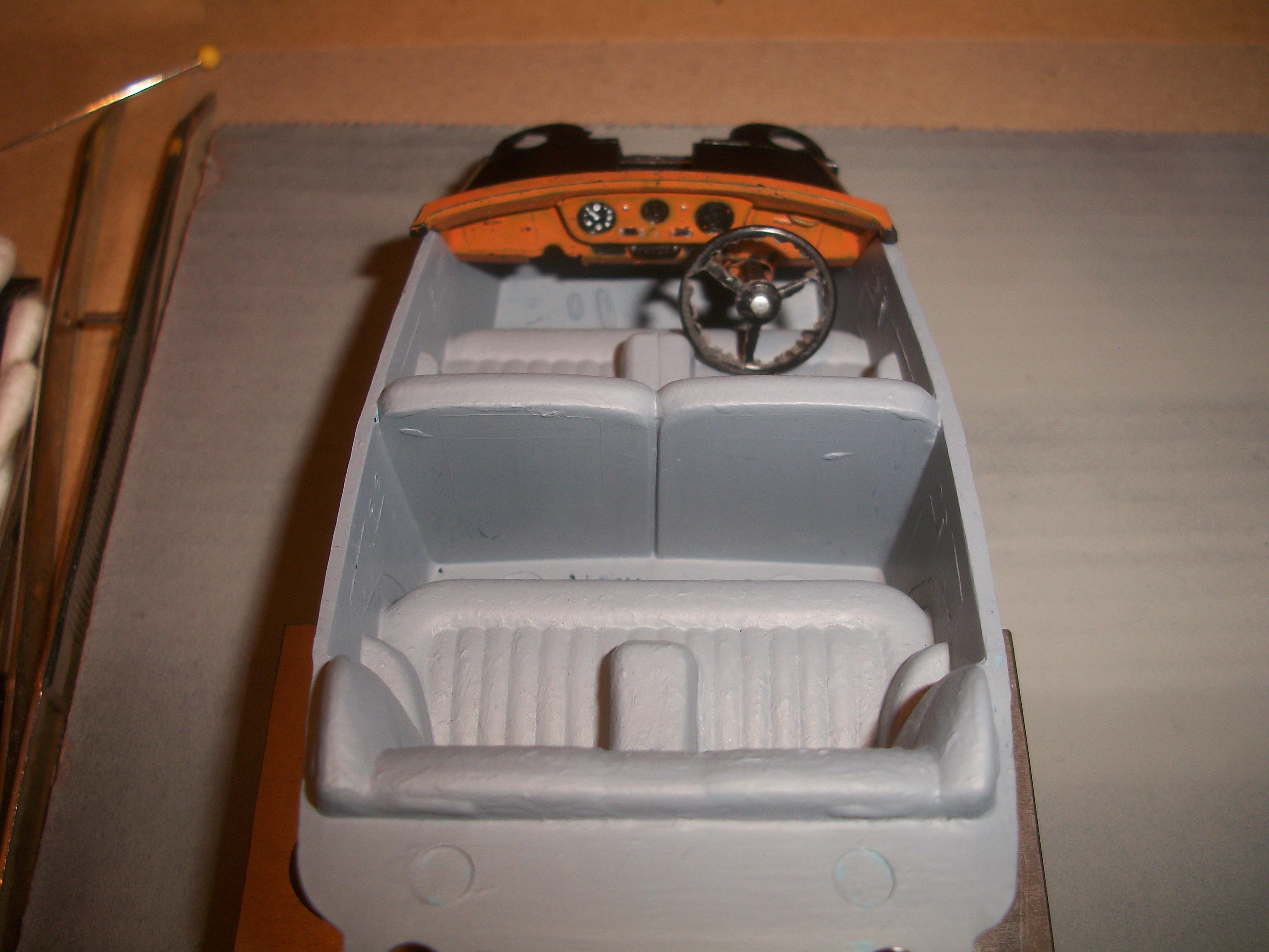
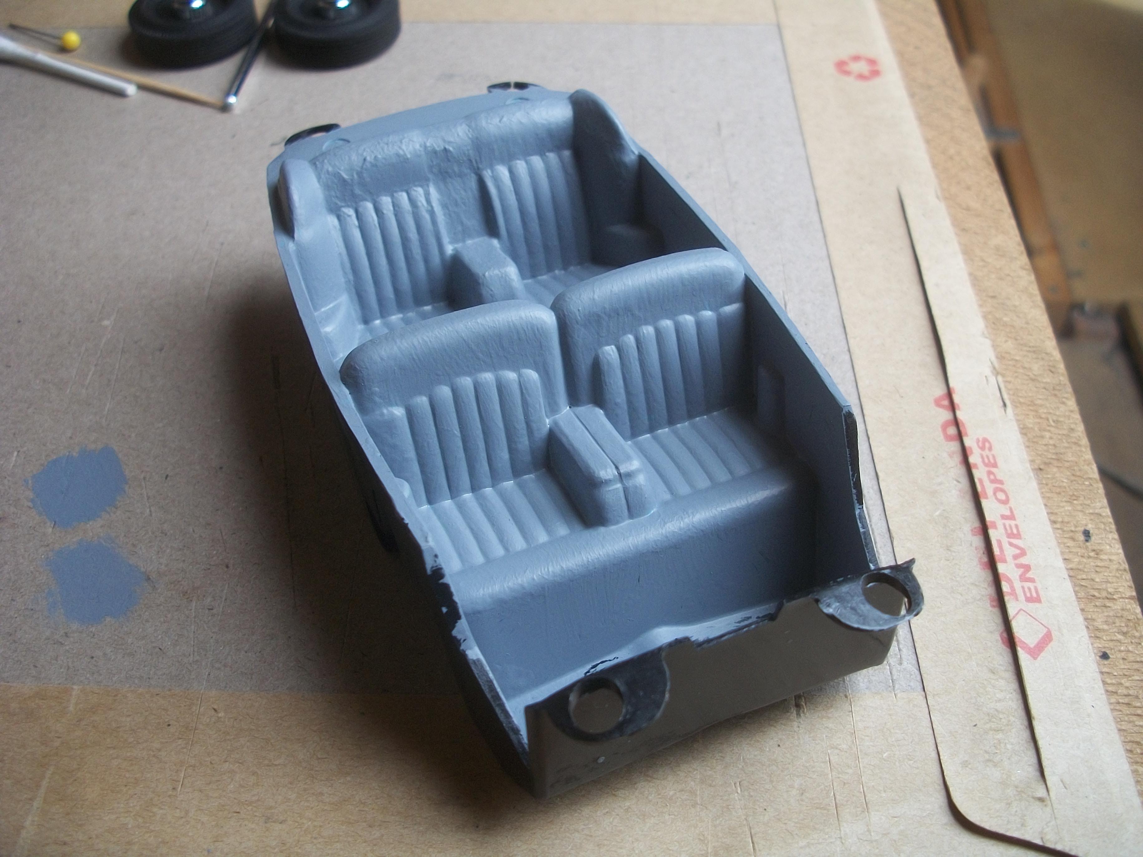
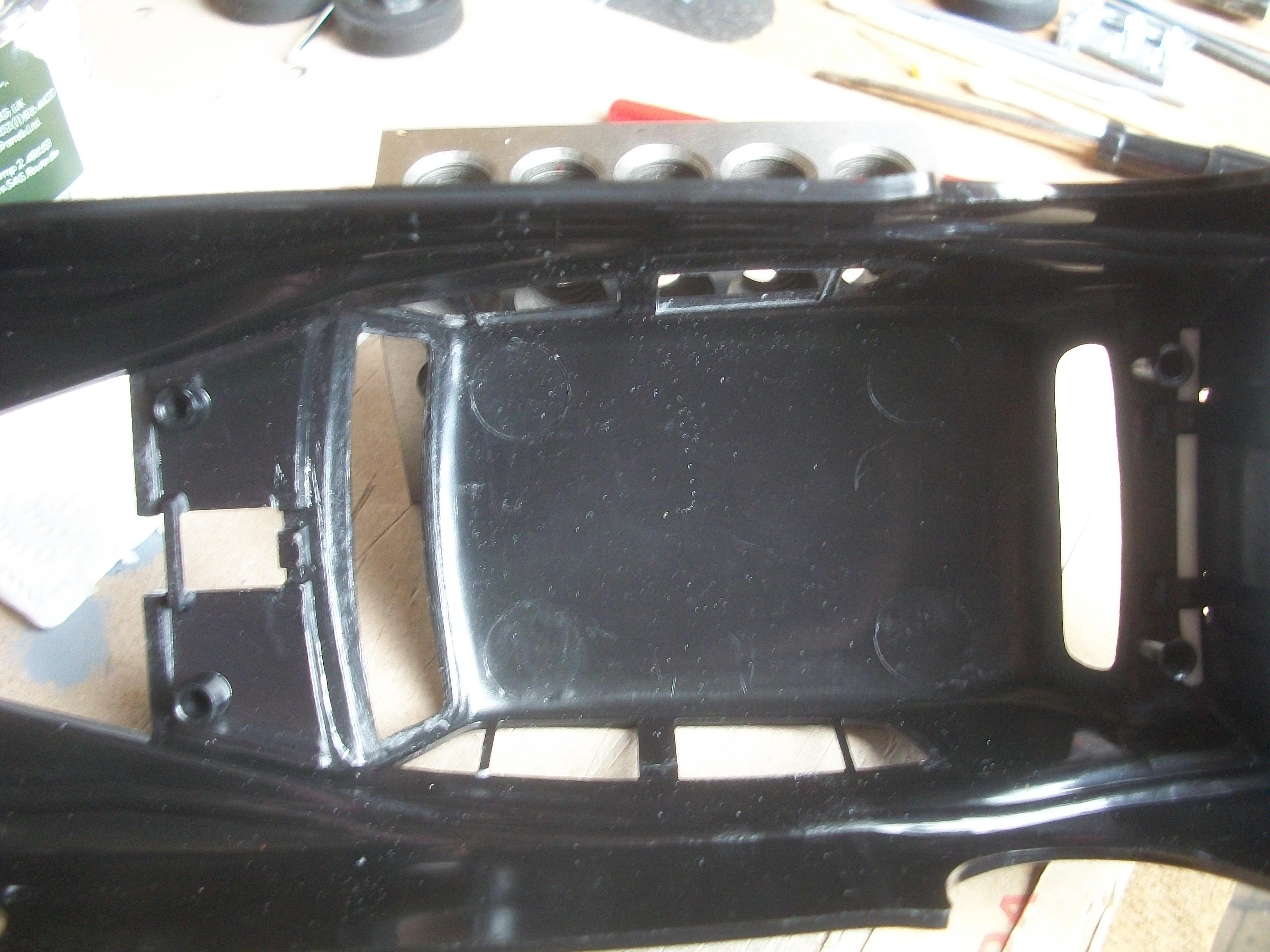
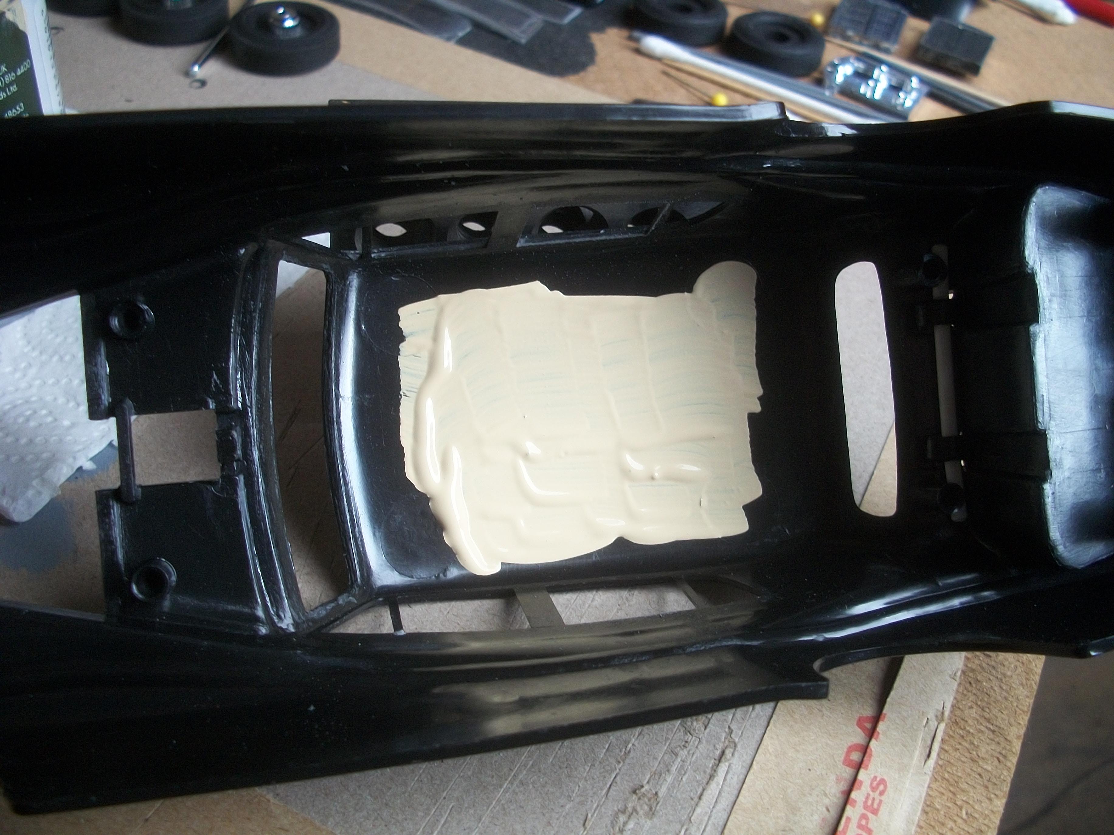
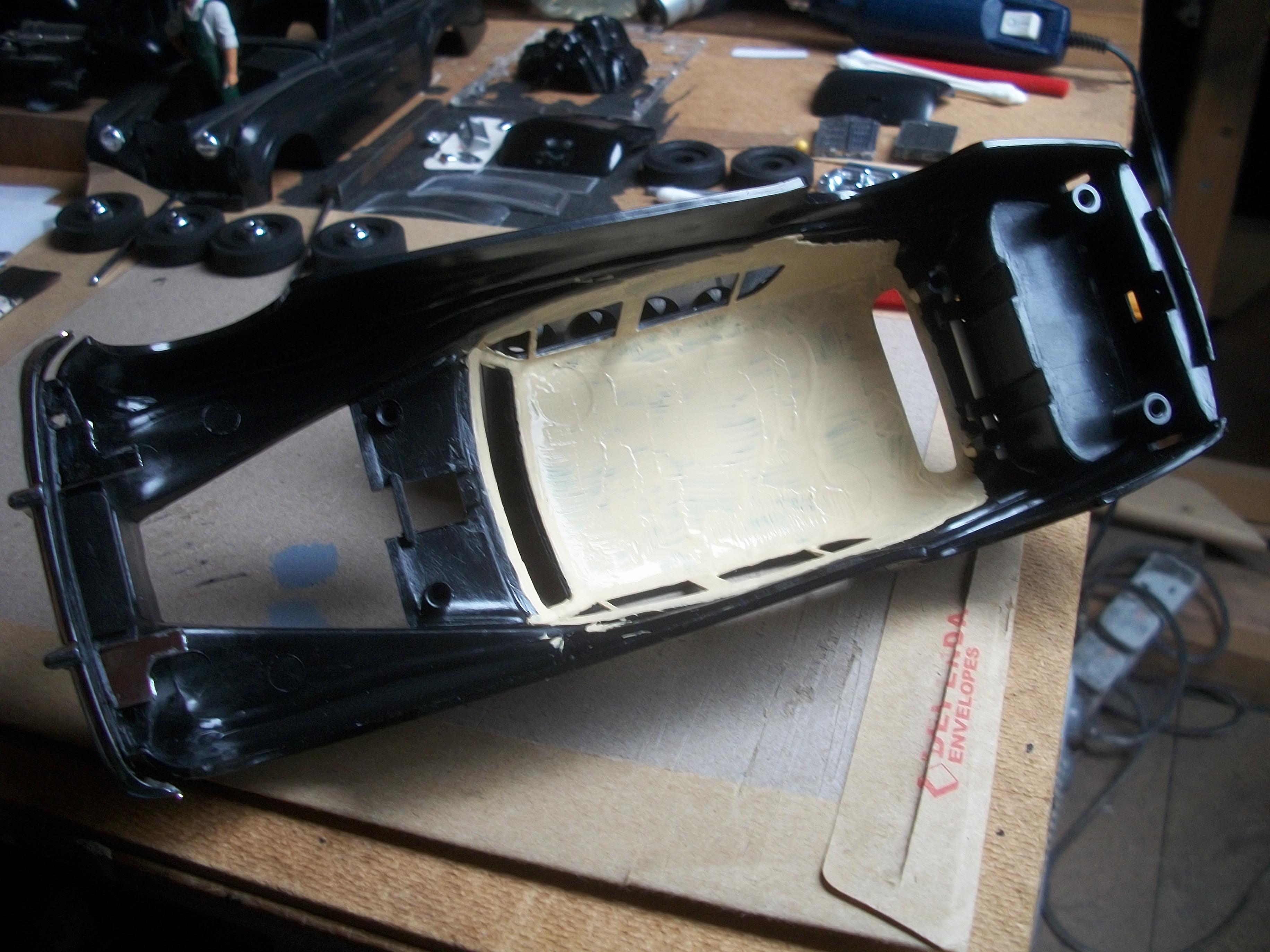
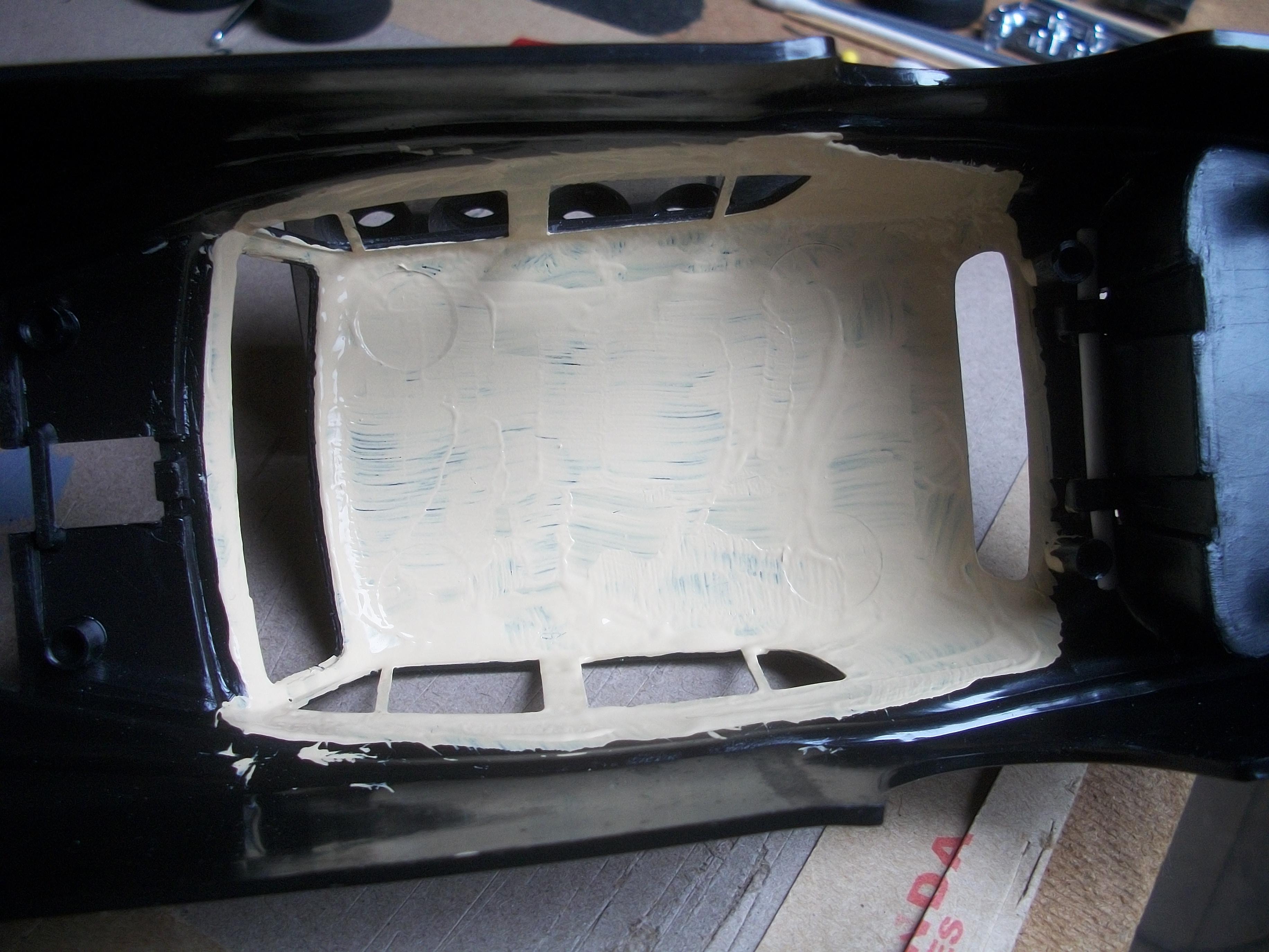
Having established that the interior seating and upholstery colour is light grey, I have applied Vallejo acrylic Light Grey over the light blue that was previously applied . . . This is using the interior tub from the previous paint testing, and not the Entex interior tub that goes with the body shell that I am working on. Later, there will be grey felt carpets added, and also a beige headlining. One possibility is that I might use masking tape for the headlining, as it has a cream coloured texture to it . . . David
-
Rolls-Royce No Chemicals, No Paint, No Harmful Glues
Anglia105E replied to Anglia105E's topic in WIP: Model Cars
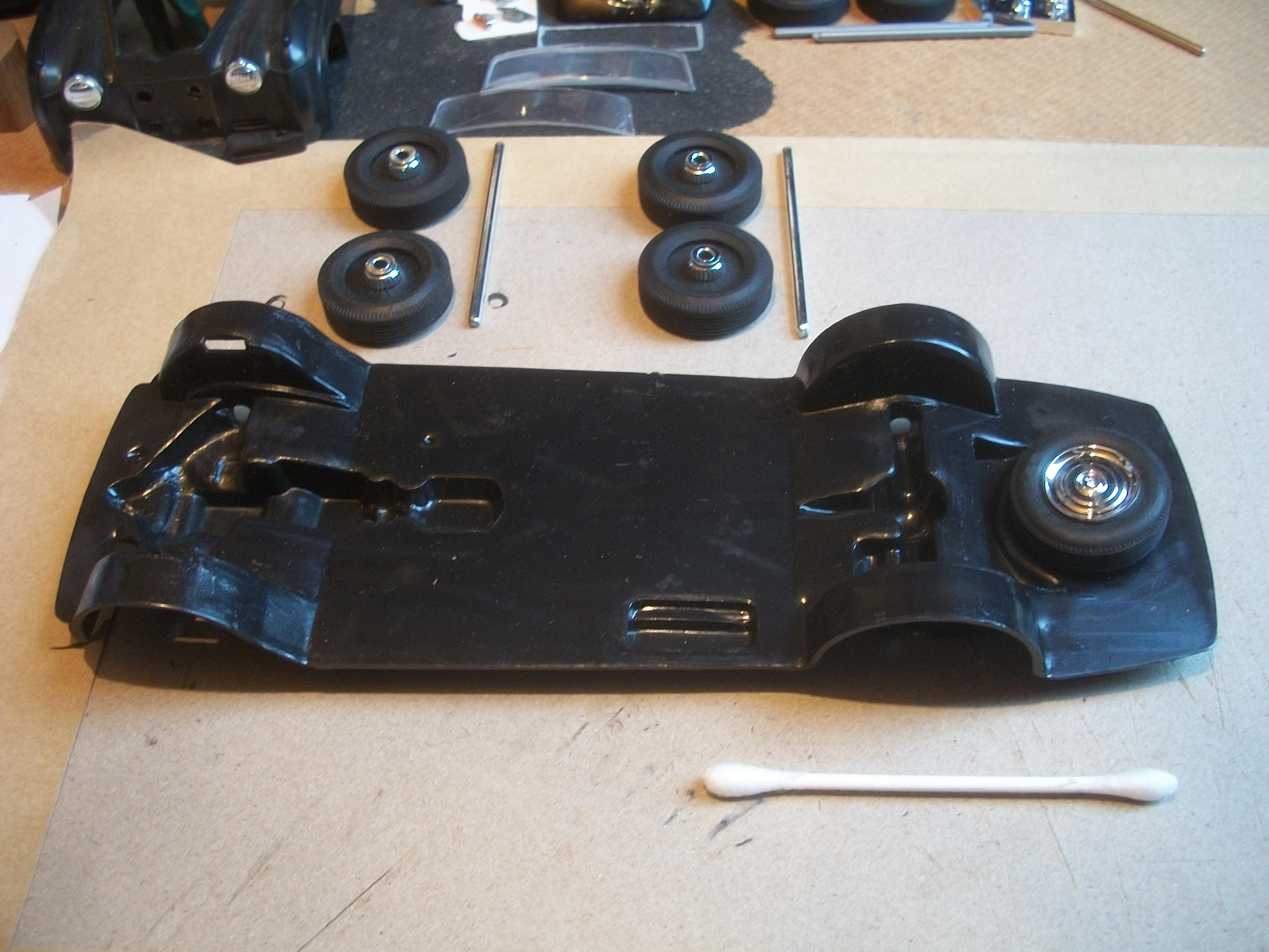
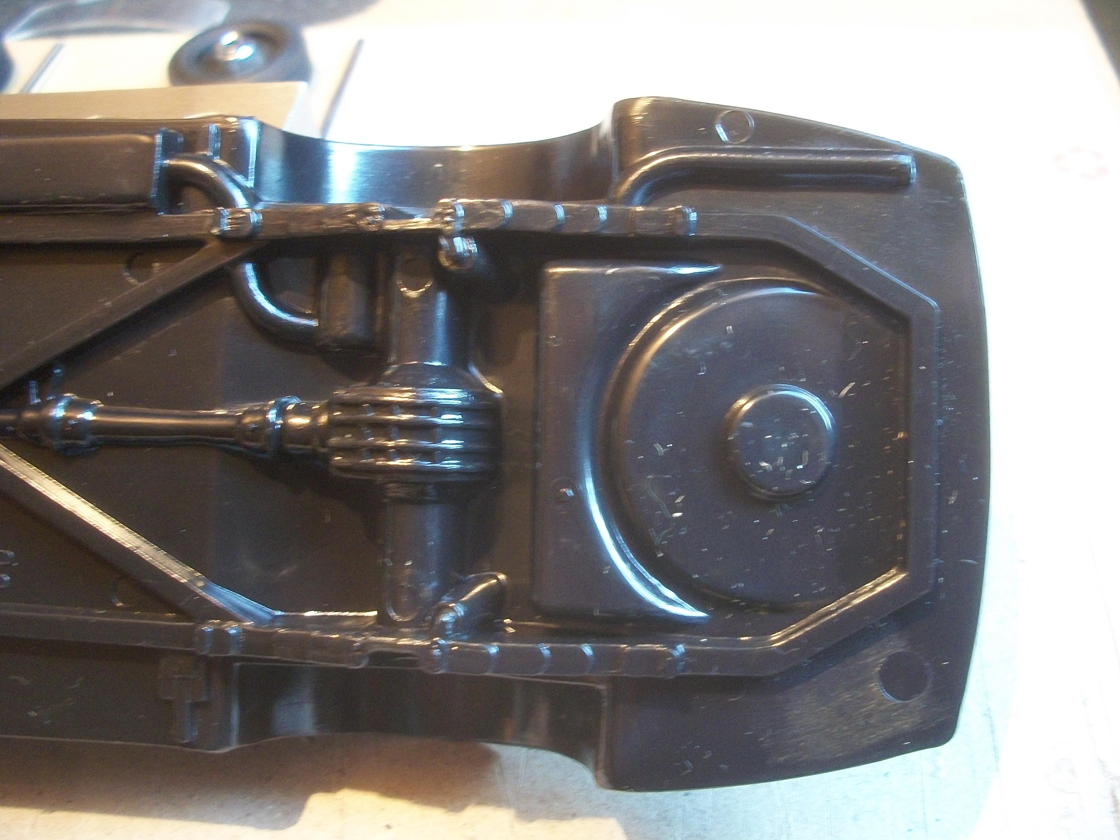
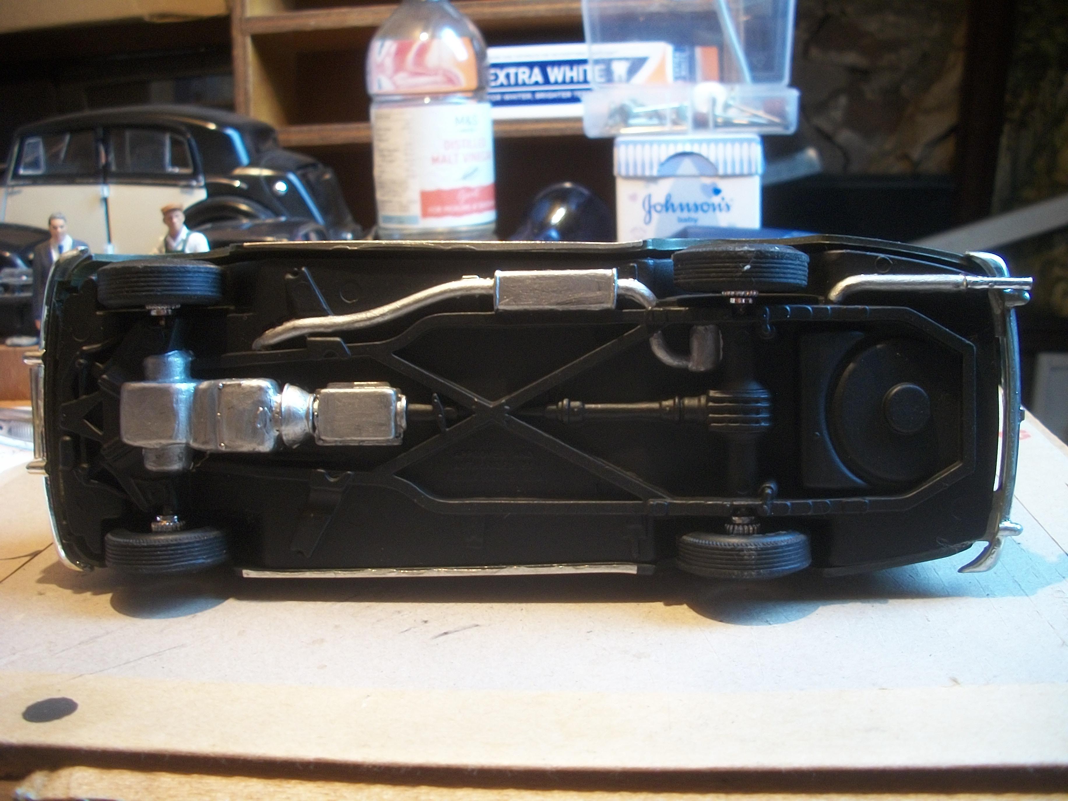
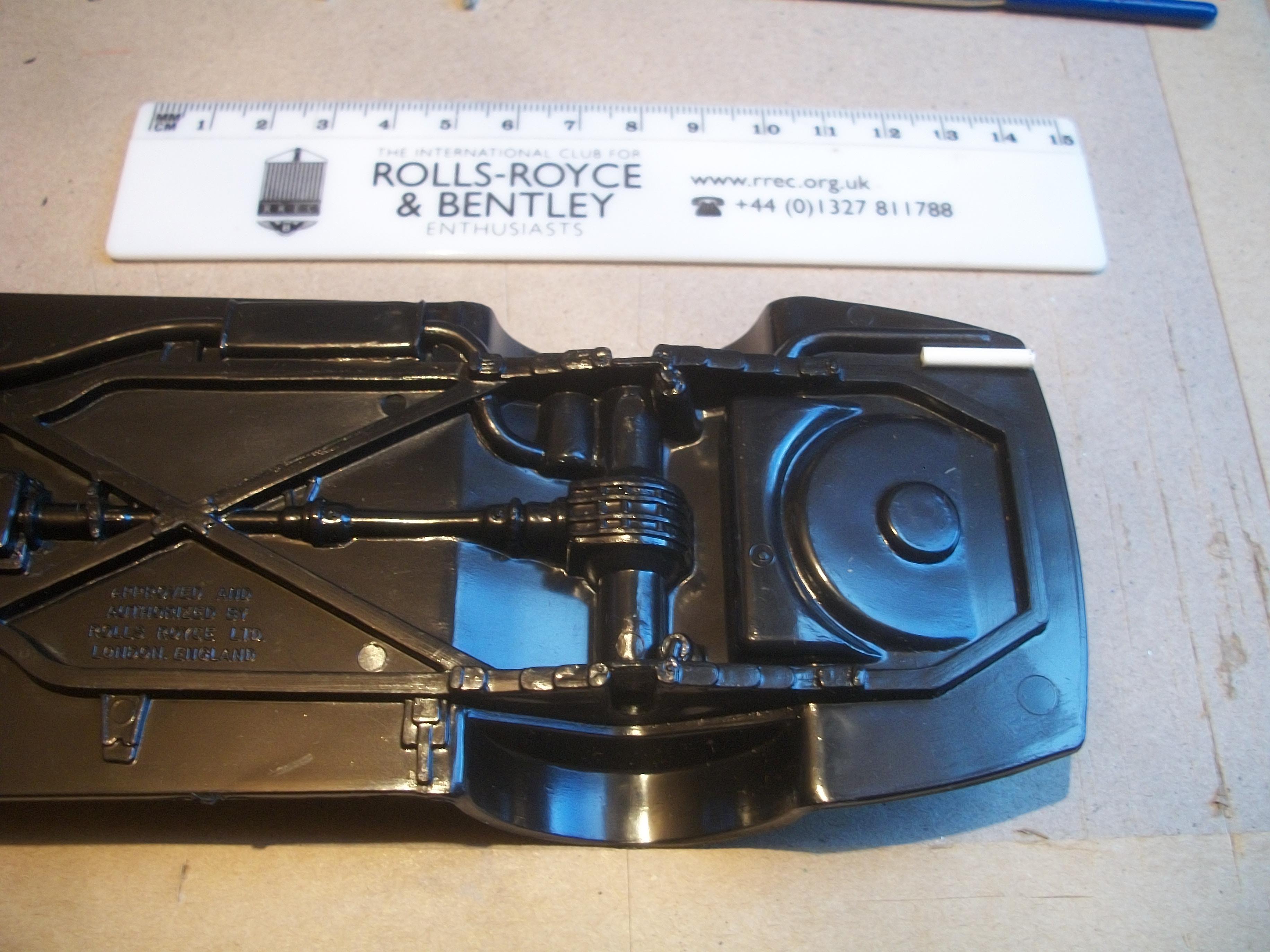
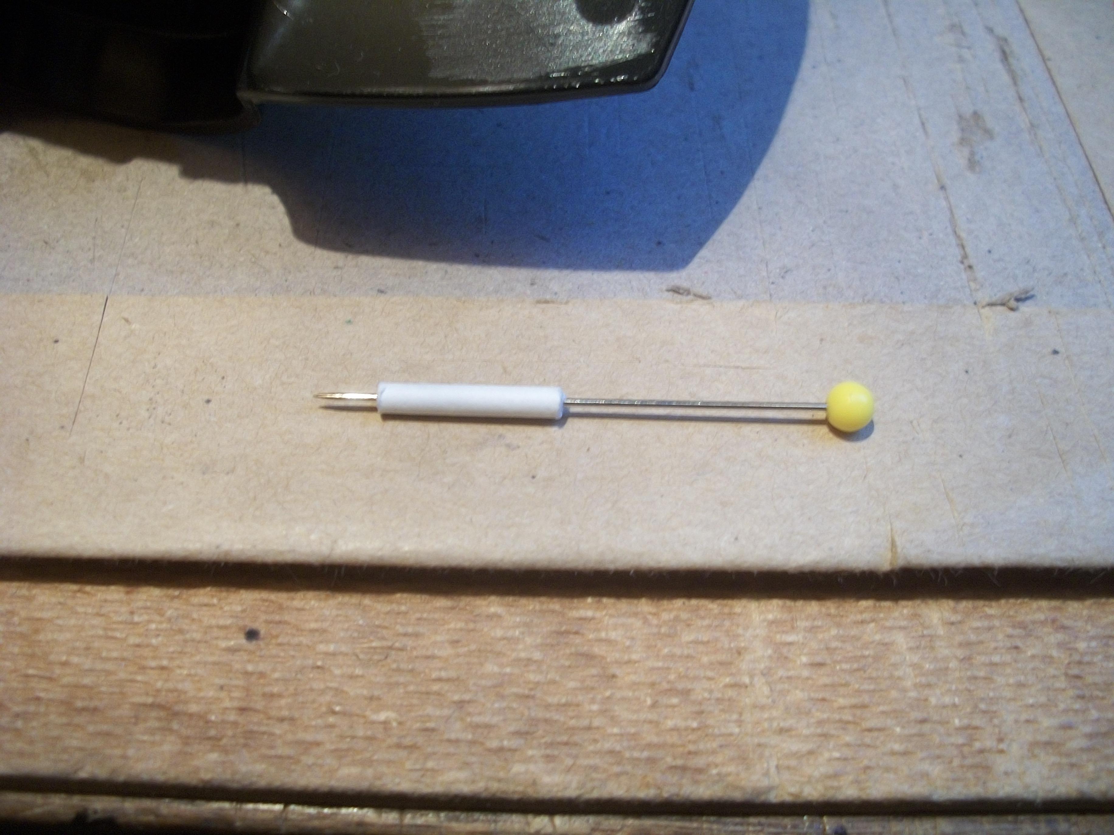
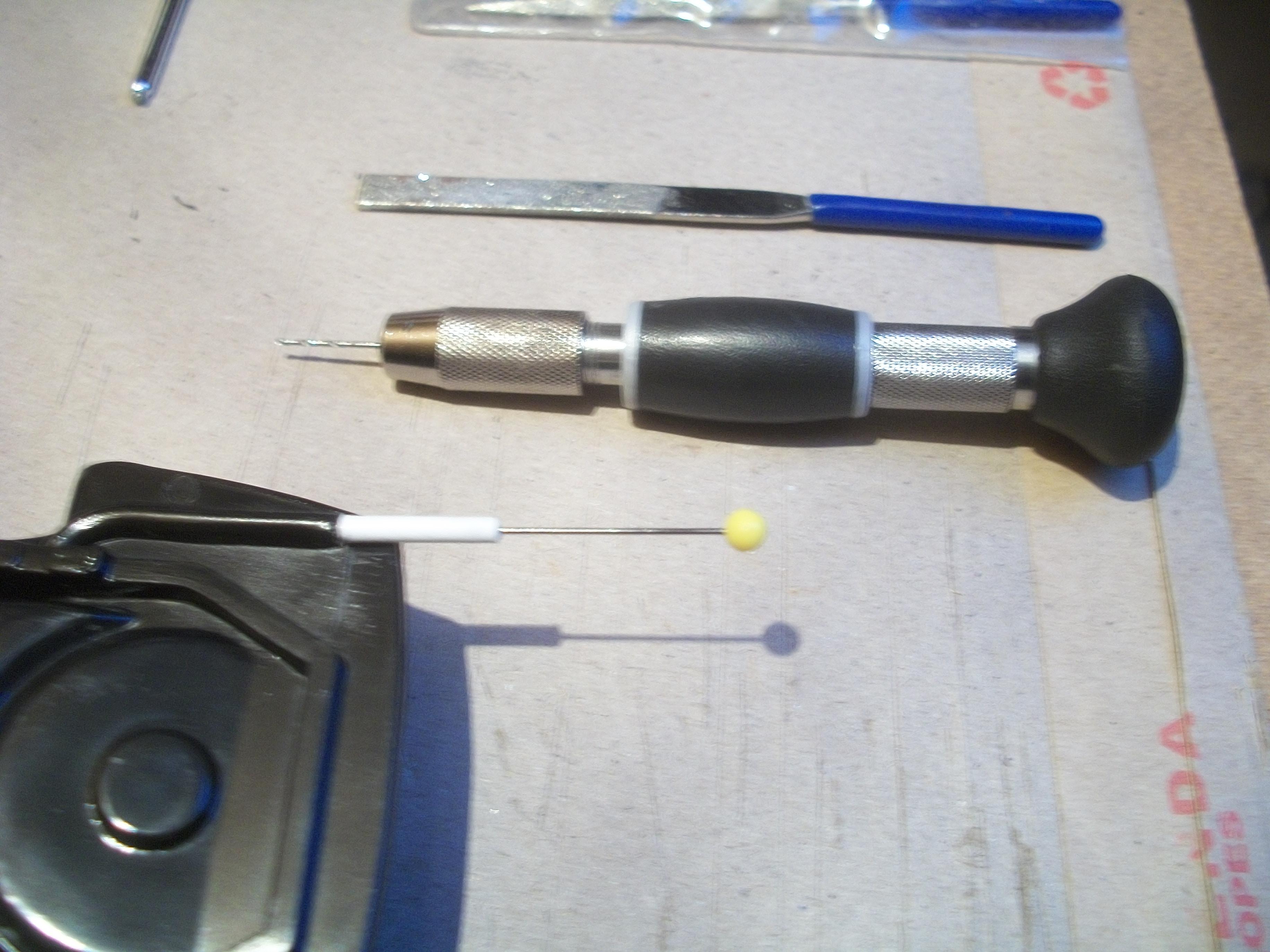
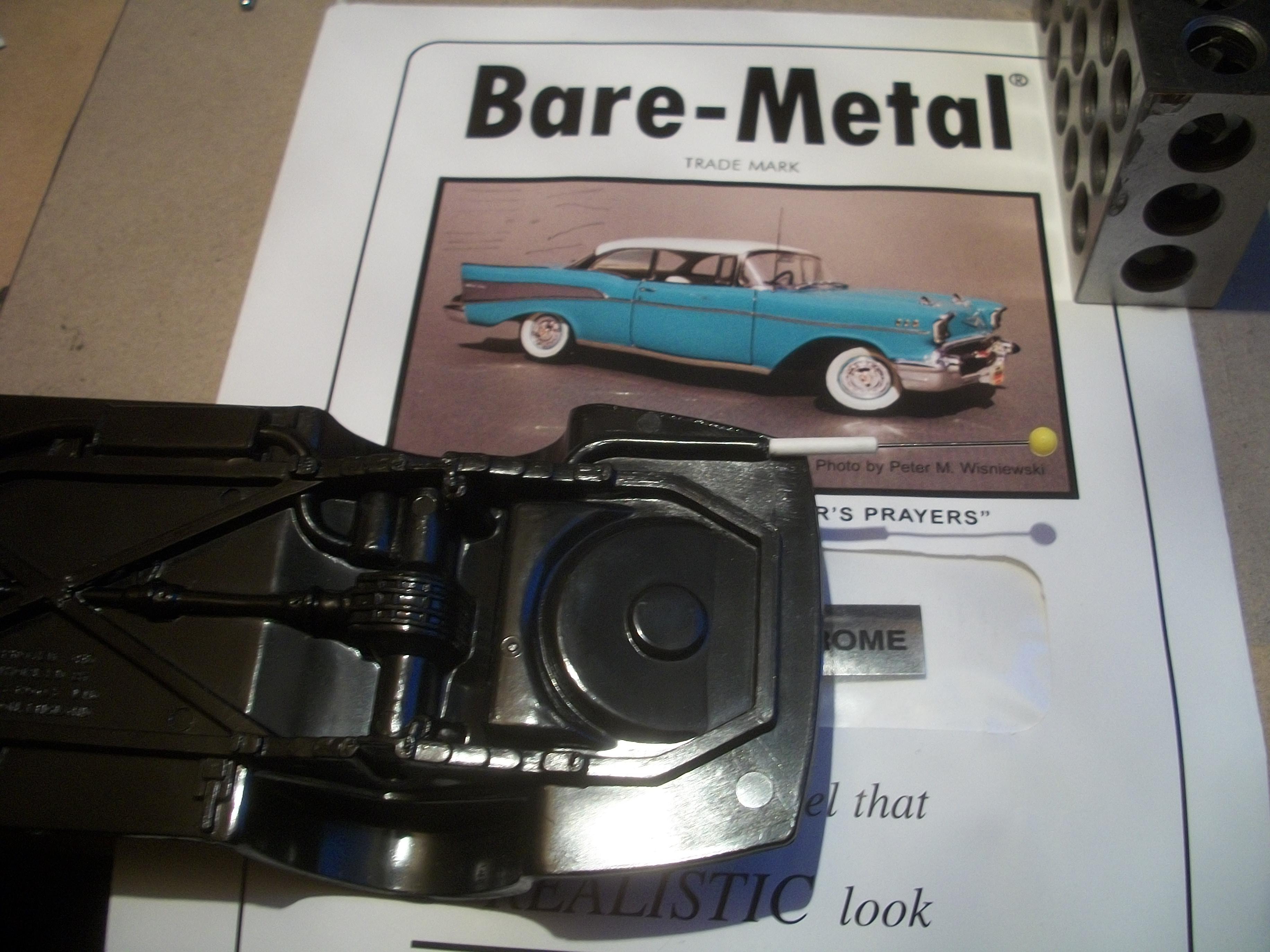
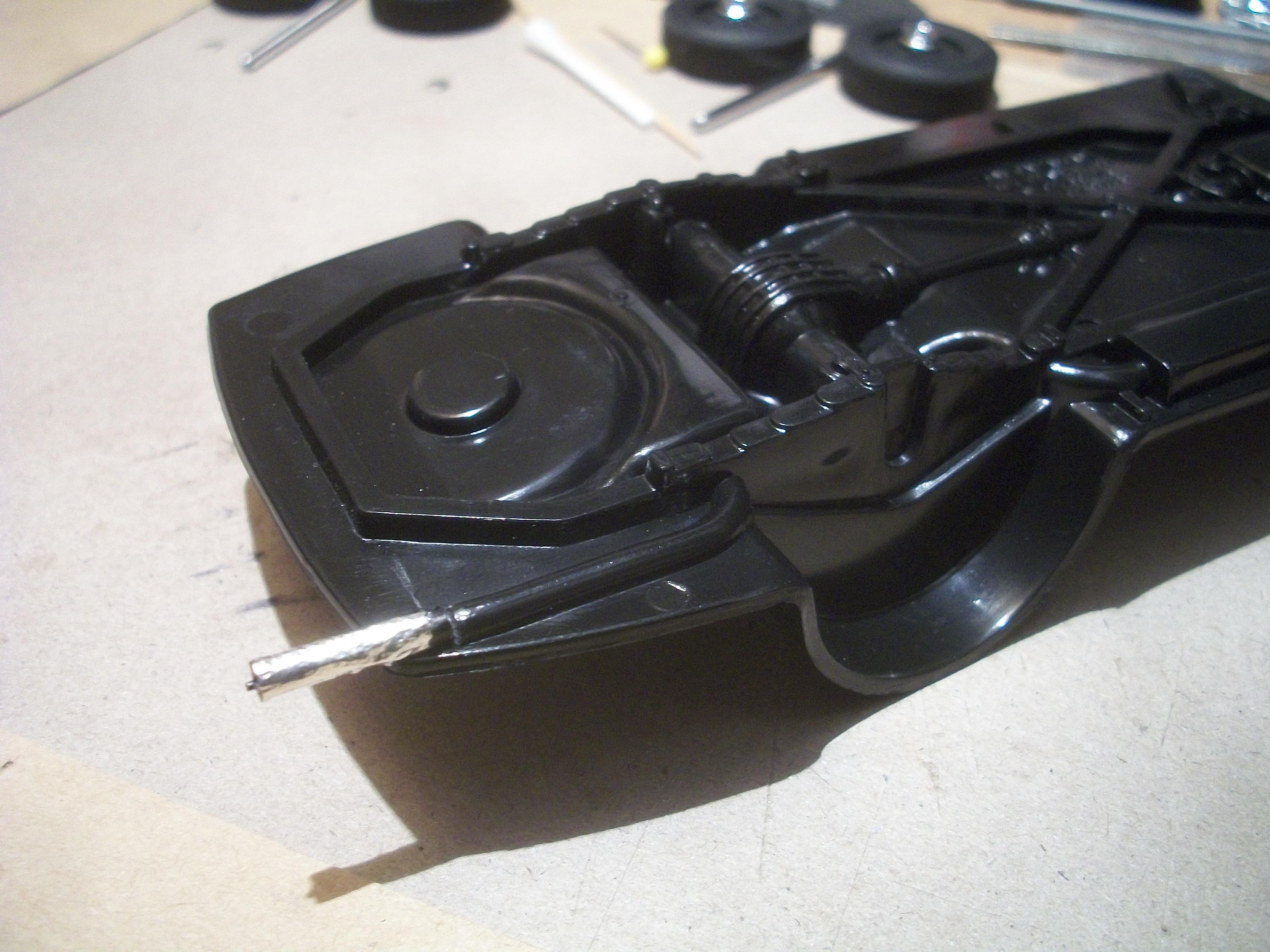
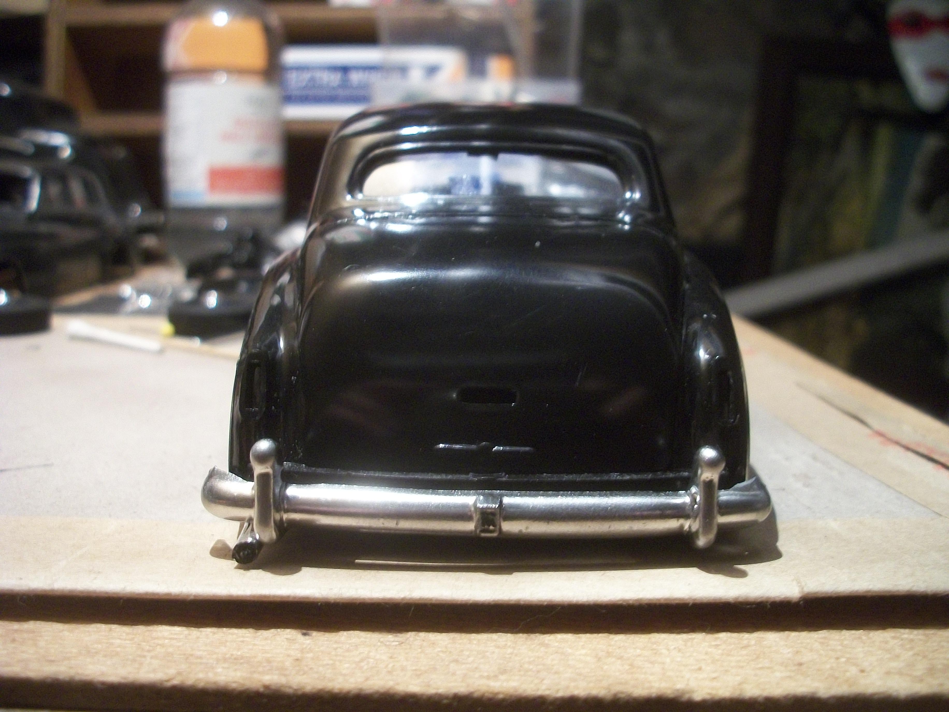
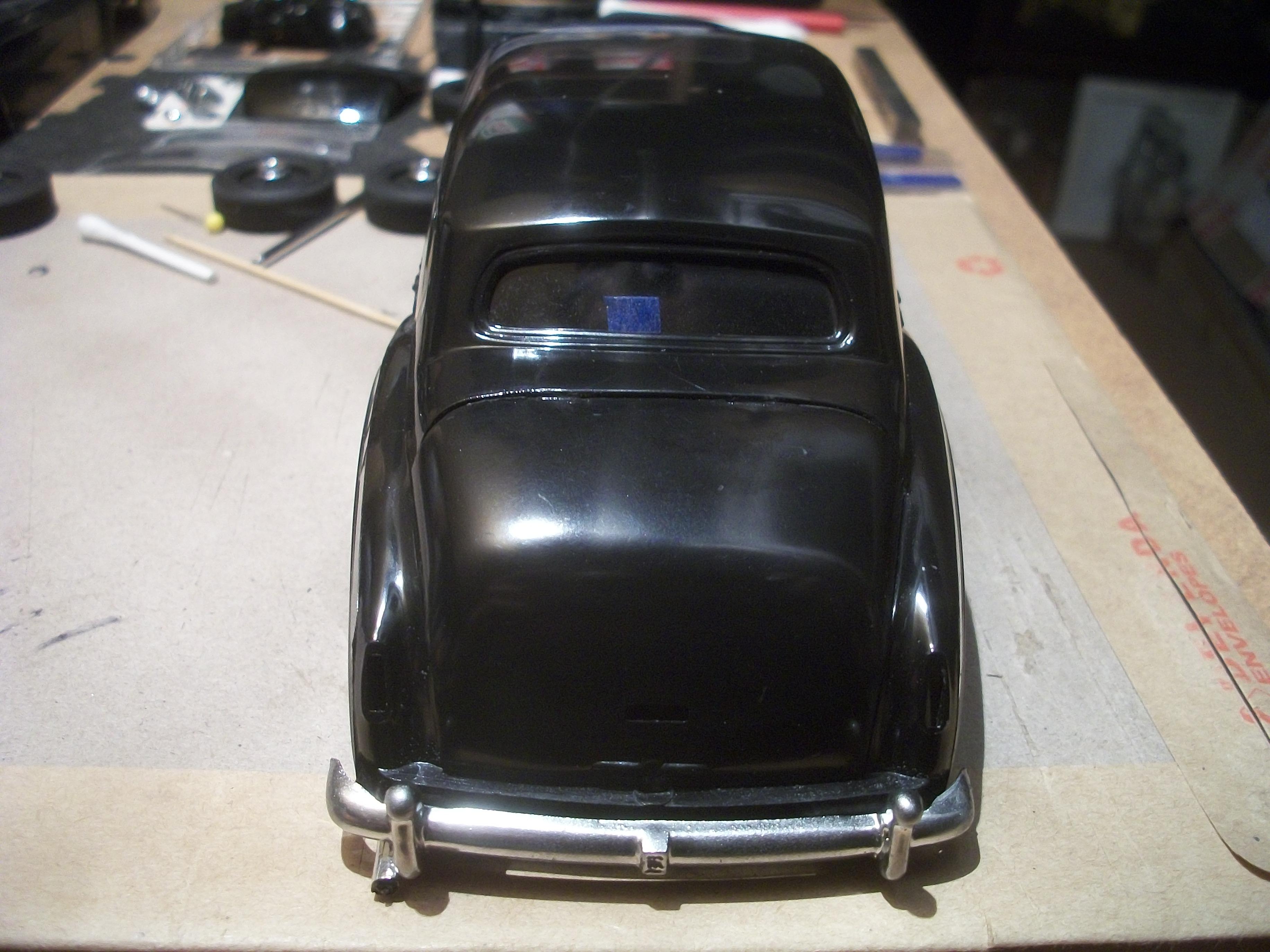
Today I set about fabricating an exhaust tailpipe for the Silver Cloud, and previously I would have used super glue and Liquid Chrome for this part. However, this time I needed to find a method of making the part without resorting to any solvent or chemical based materials . . . The exhaust system is moulded into the chassis rather crudely, and the rear section of the exhaust ends short of the where the chassis floor ends, This would be correct, except all Silver Cloud cars had a chrome plated tailpipe which extends just beyond the rear bumper, and immediately next to the overrider. This part is not supplied in the kit. First of all, I measured and cut a 14 mm length of cotton bud stalk, and this was drilled out along it's centre lengthways. Another hole was drilled into the end of the exhaust pipe on the chassis . . . Then a quilting pin was pushed through the hole in the tailpipe, and inserted into the end of the exhaust pipe on the chassis floor. The white tailpipe was covered with Bare Metal Foil, and after cutting off the surplus quilting pin, the tip of the tailpipe was blackened with a permanent marker pen . . . The end result seems to have worked, and I am pleased because the idea came into my head out of nowhere. I used my Revell hand drill to fabricate the holes. One of the following photos shows the tailpipe as it was done on a previous build of mine ( photo number 101_0399 ) . . . David -
Rolls-Royce No Chemicals, No Paint, No Harmful Glues
Anglia105E replied to Anglia105E's topic in WIP: Model Cars
Today I set about fabricating an exhaust tailpipe for the Silver Cloud, and previously I would have used super glue and Liquid Chrome for this part. However, this time I needed to find a method of making the part without resorting to any solvent or chemical based materials . . . The exhaust system is moulded into the chassis rather crudely, and the rear section of the exhaust ends short of the where the chassis floor ends, This would be correct, except all Silver Cloud cars had a chrome plated tailpipe which extends just beyond the rear bumper, and immediately next to the overrider. This part is not supplied in the kit. First of all, I measured and cut a 14 mm length of cotton bud stalk, and this was drilled out along it's centre lengthways. Another hole was drilled into the end of the exhaust pipe on the chassis . . . Then a quilting pin was pushed through the hole in the tailpipe, and inserted into the end of the exhaust pipe on the chassis floor. The white tailpipe was covered with Bare Metal Foil, and after cutting off the surplus quilting pin, the tip of the tailpipe was blackened with a permanent marker pen . . . The end result seems to have worked, and I am pleased because the idea came into my head out of nowhere. I used my Revell hand drill to fabricate the holes. One of the following photos shows the tailpipe as it was done on a previous build of mine ( photo number 101_0399 ) . . . David
-
Rolls-Royce No Chemicals, No Paint, No Harmful Glues
Anglia105E replied to Anglia105E's topic in WIP: Model Cars
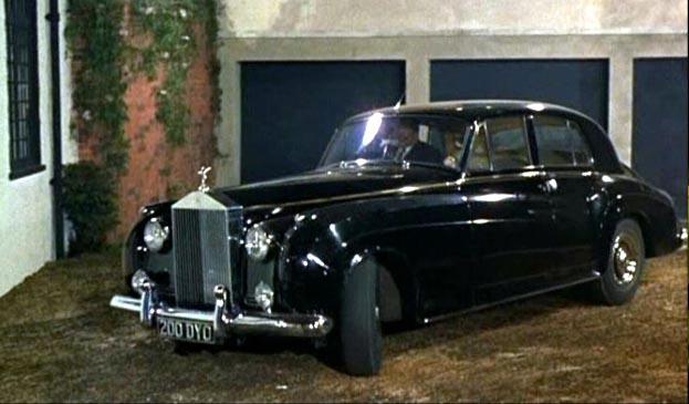
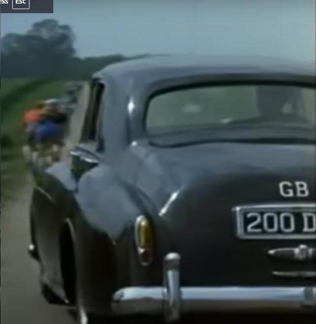
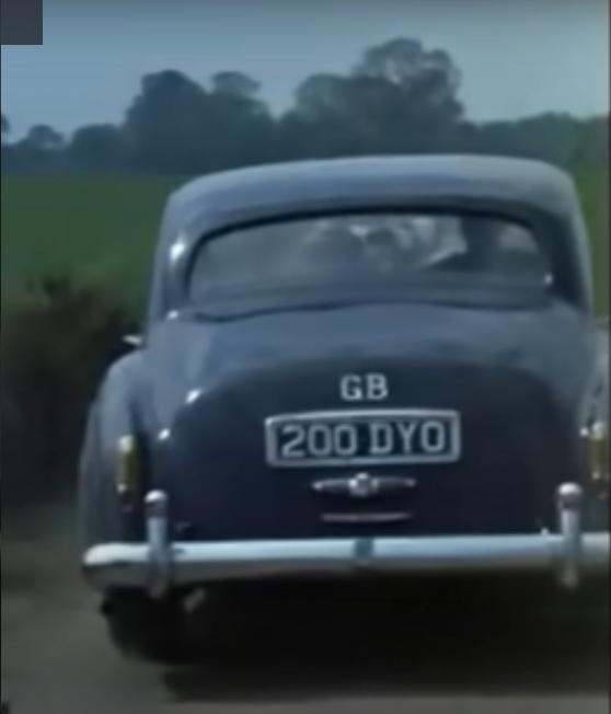
The RREC here in England responded to my enquiry message within 12 hours, during the following day. The Rolls-Royce Owners' Club of North America however, have not responded to my enquiry at all during the past seven days . . . There could be any number of reasons for this, and I won't dwell on them. The Texas license plate for the car that I chose to base my model on was not a valid license plate, and I was not able to validate the UK registration plate either, so I have chosen an alternative motor car for my build . . . This is a 1957 black Rolls-Royce Silver Cloud, registration number 200 DYO which has a verified chassis number of SDD54 . This car appeared in the opening sequence of a British film . The Fast Lady ' in 1962, and I have viewed the film to check this detail. Also, I checked the DVLA database, which is the official government website used to verify every motor vehicle ever registered historically. The car registered as 200 DYO is taxed until February of 2026, so this actual Rolls-Royce Silver Cloud is still on the road today, since it was built in 1957. Here are three images obtained from the film, in which the car was driven by James Robertson Justice . . . David