Anglia105E
-
Posts
3,486 -
Joined
-
Last visited
Content Type
Profiles
Forums
Events
Gallery
Everything posted by Anglia105E
-
Rolls-Royce No Chemicals, No Paint, No Harmful Glues
Anglia105E replied to Anglia105E's topic in WIP: Model Cars
I guess we have all been there, Jose . . . David -
I would agree with Luke on this one Les . . . smoked tint seems the most suitable for your model. David
-
Rolls-Royce No Chemicals, No Paint, No Harmful Glues
Anglia105E replied to Anglia105E's topic in WIP: Model Cars
Thanks a lot Steve . . . The most annoying and irritating aspect of the spillage of excess Sharpie was that it was MY fault . . . I caused the damage myself. Yes, you can say that the Sharpie marker pen was faulty, and I did get a full refund, but the Entex Silver Cloud body was in perfect condition before I got my hands on it. Anyway, all is not lost and I can move forward with a much more positive approach, which is the most important lesson to have learned . . . David -
Rolls-Royce No Chemicals, No Paint, No Harmful Glues
Anglia105E replied to Anglia105E's topic in WIP: Model Cars
Many thanks for your kind thoughts Don, and take it easy as you go . . . I think once you start building scale model cars you can't stop. No sooner is one car built and finished, then the next project is on the table. In my case the car models expanded to the world of dioramas, which I believe becomes even more addictive and obsessional, if that is possible . . . From the moment that you enter that smaller world, where you can lose yourself among the figures, the buildings, the streets, trees, railways, lighting and everything in miniature . . . there is no going back. David -
Rolls-Royce No Chemicals, No Paint, No Harmful Glues
Anglia105E replied to Anglia105E's topic in WIP: Model Cars
All tips are most welcome John . . . Thank you. David -
Rolls-Royce No Chemicals, No Paint, No Harmful Glues
Anglia105E replied to Anglia105E's topic in WIP: Model Cars
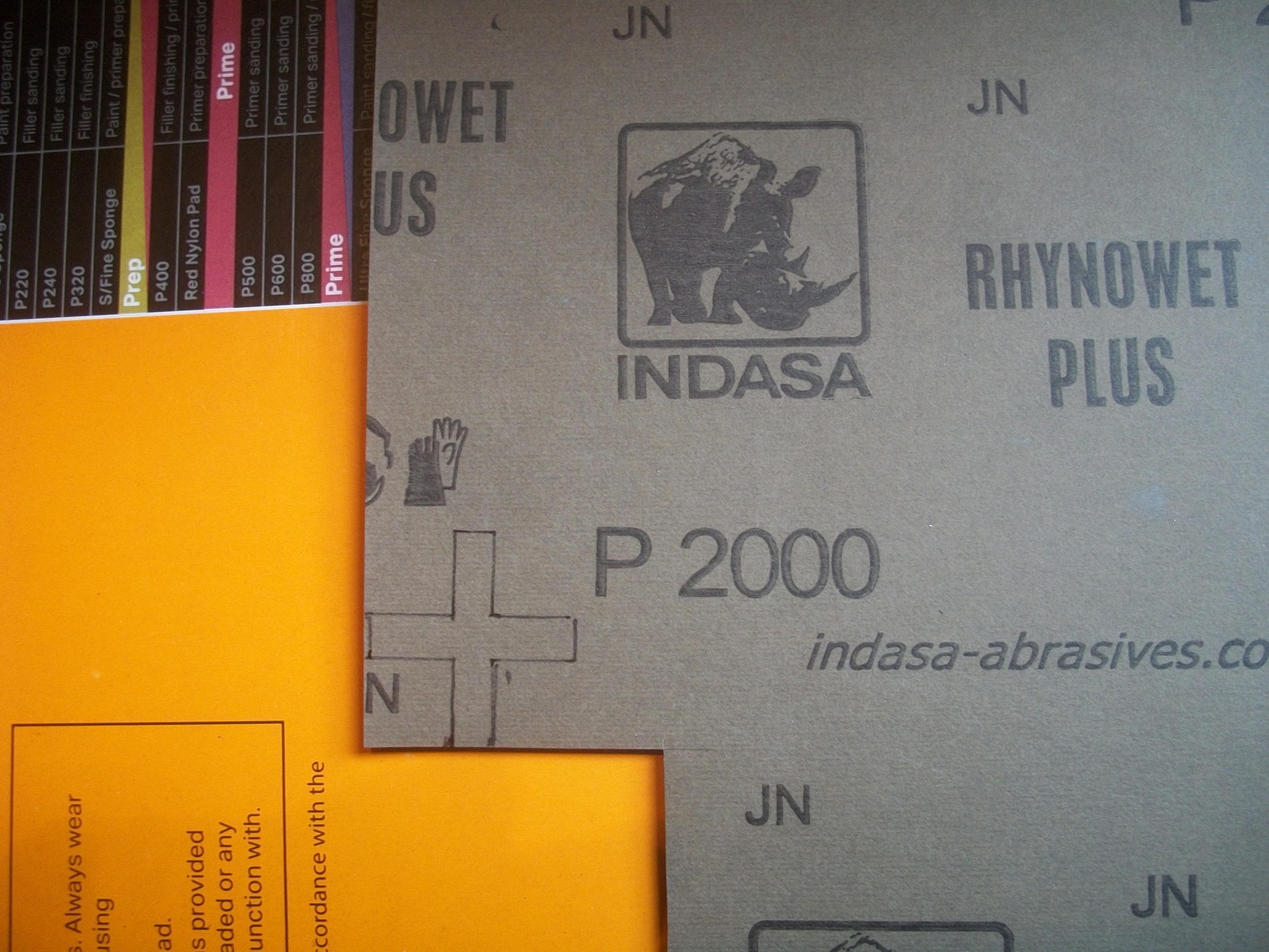
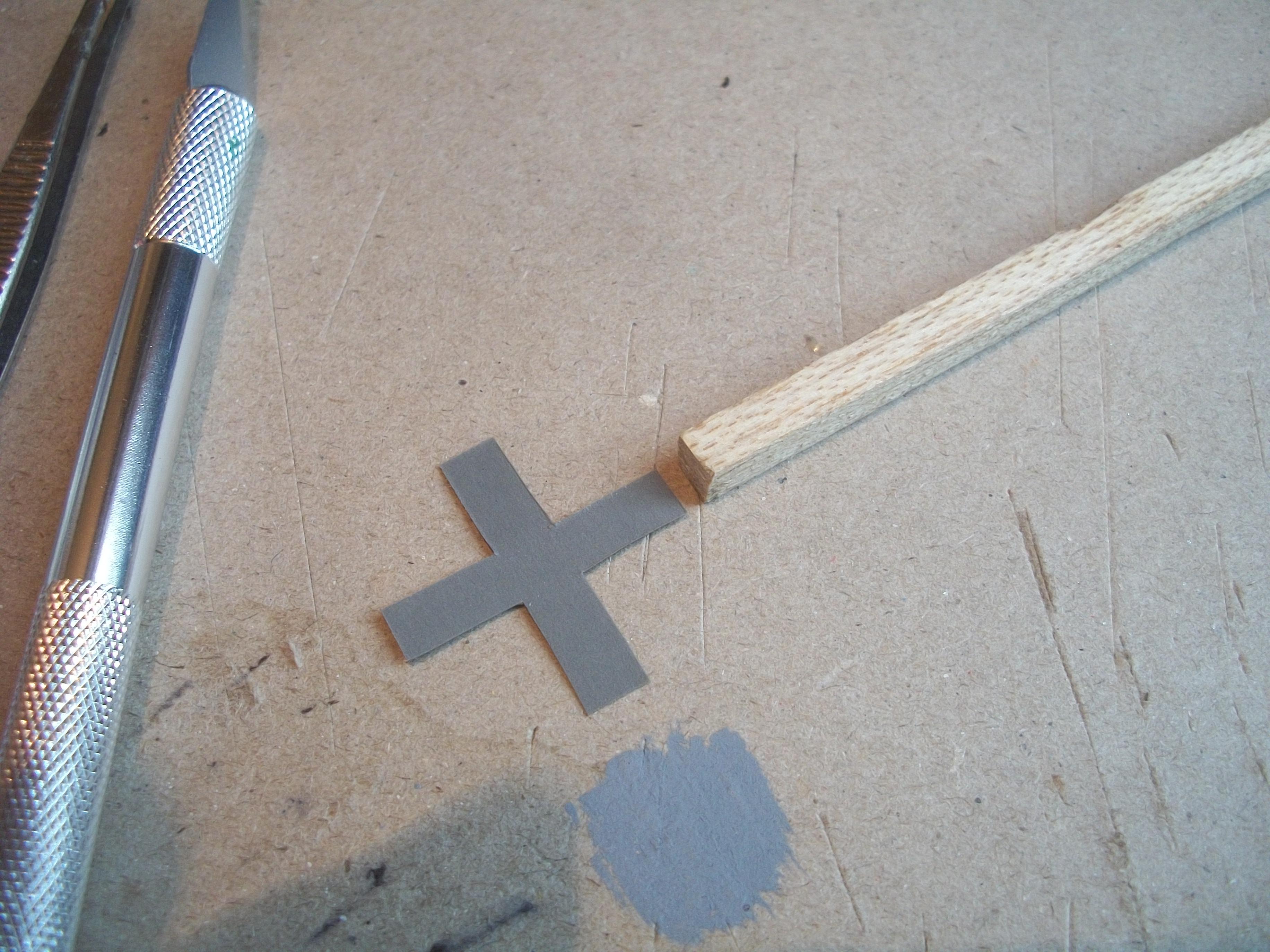
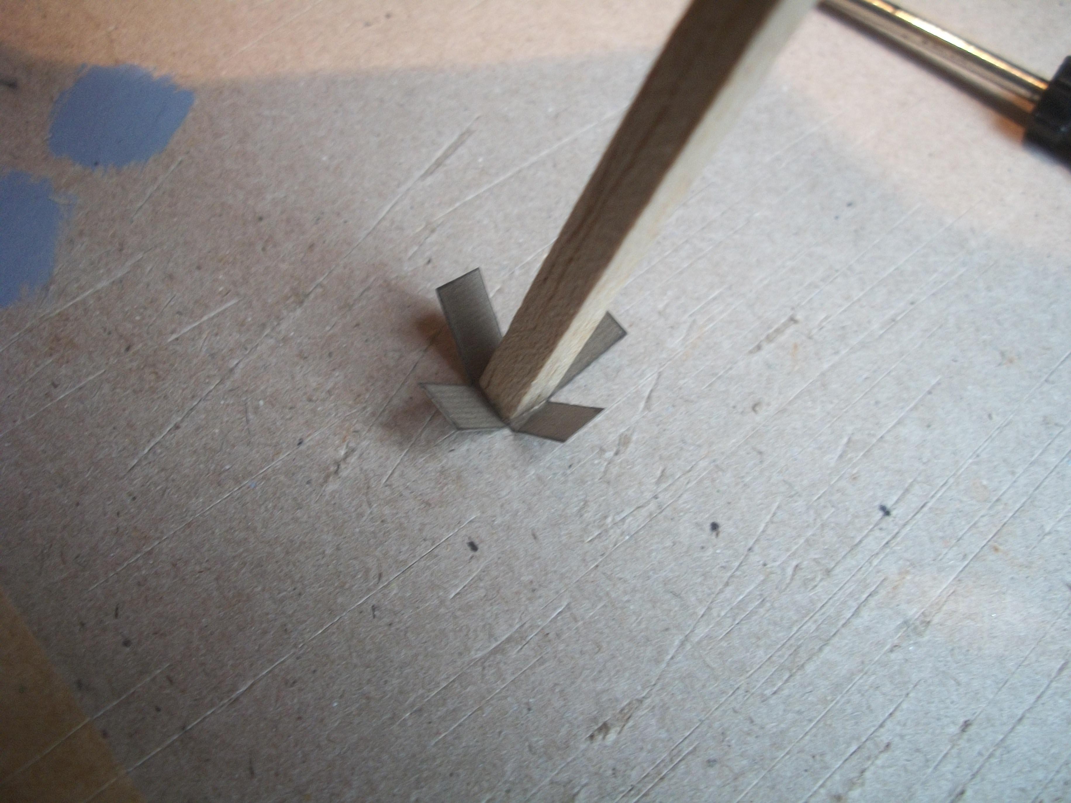
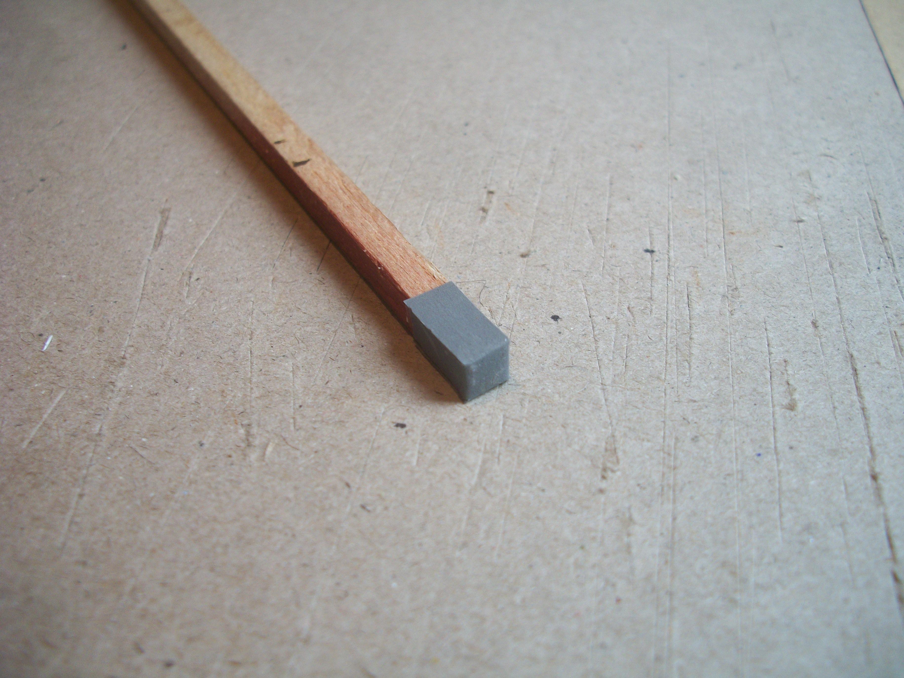
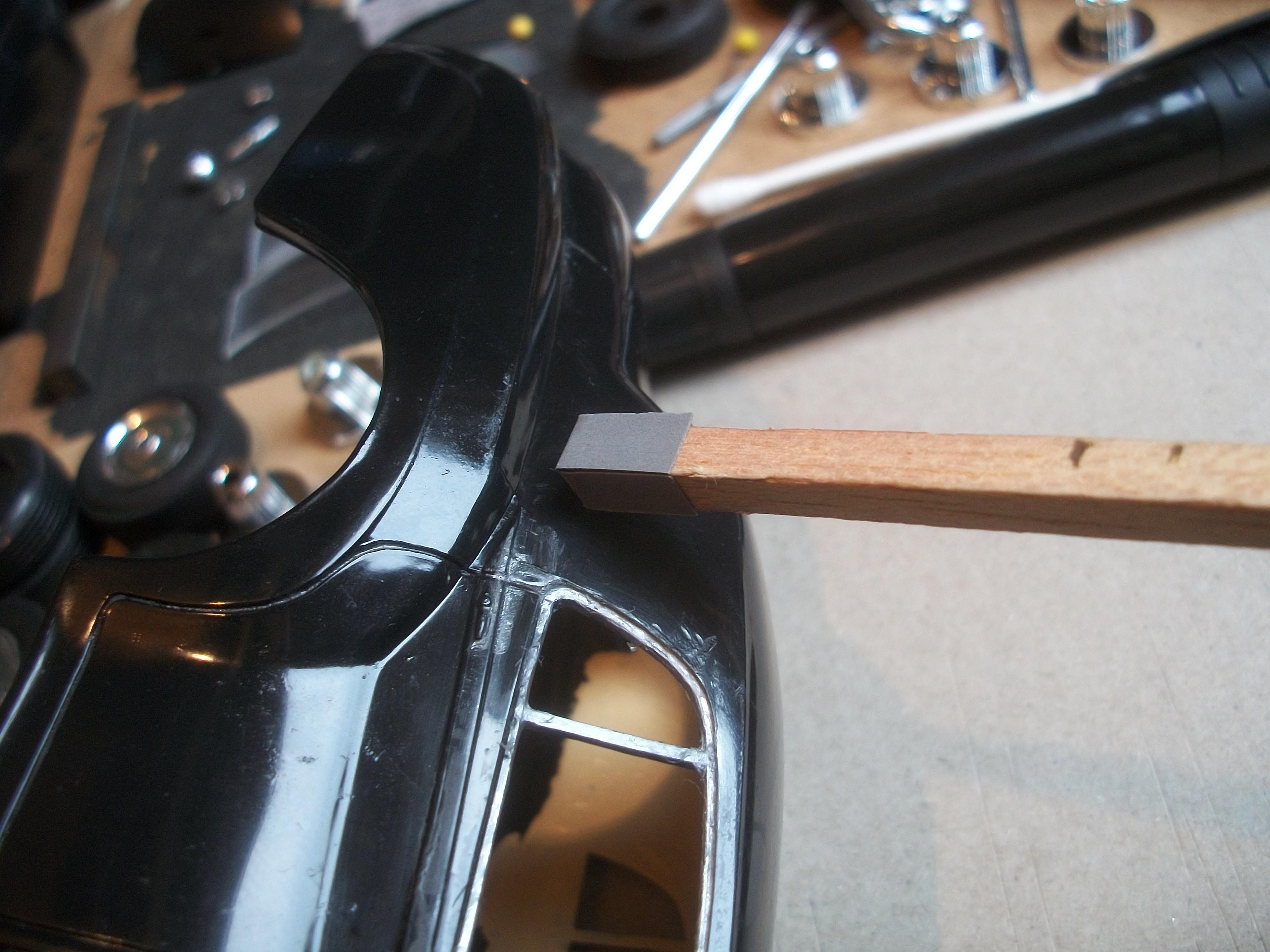
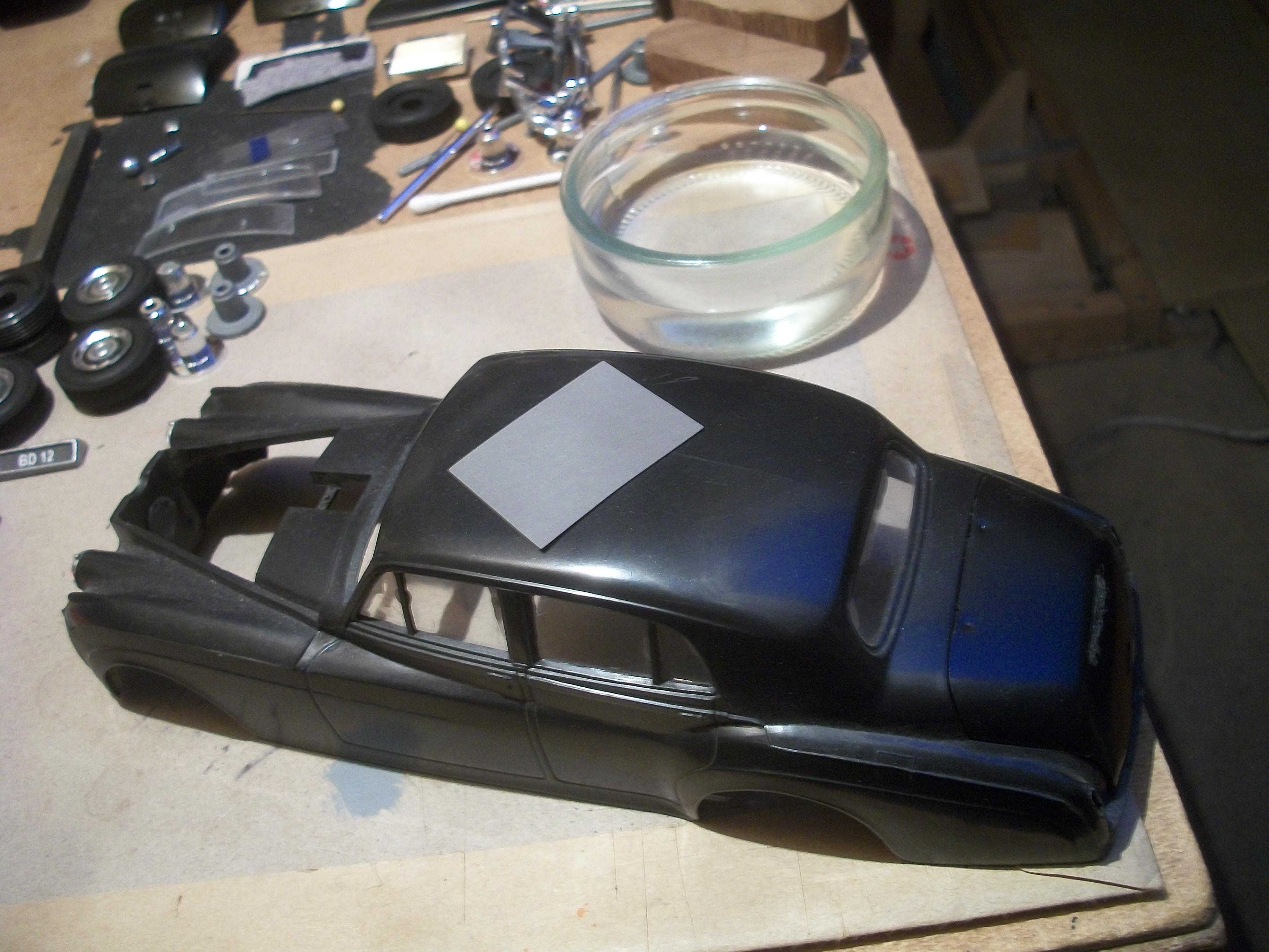
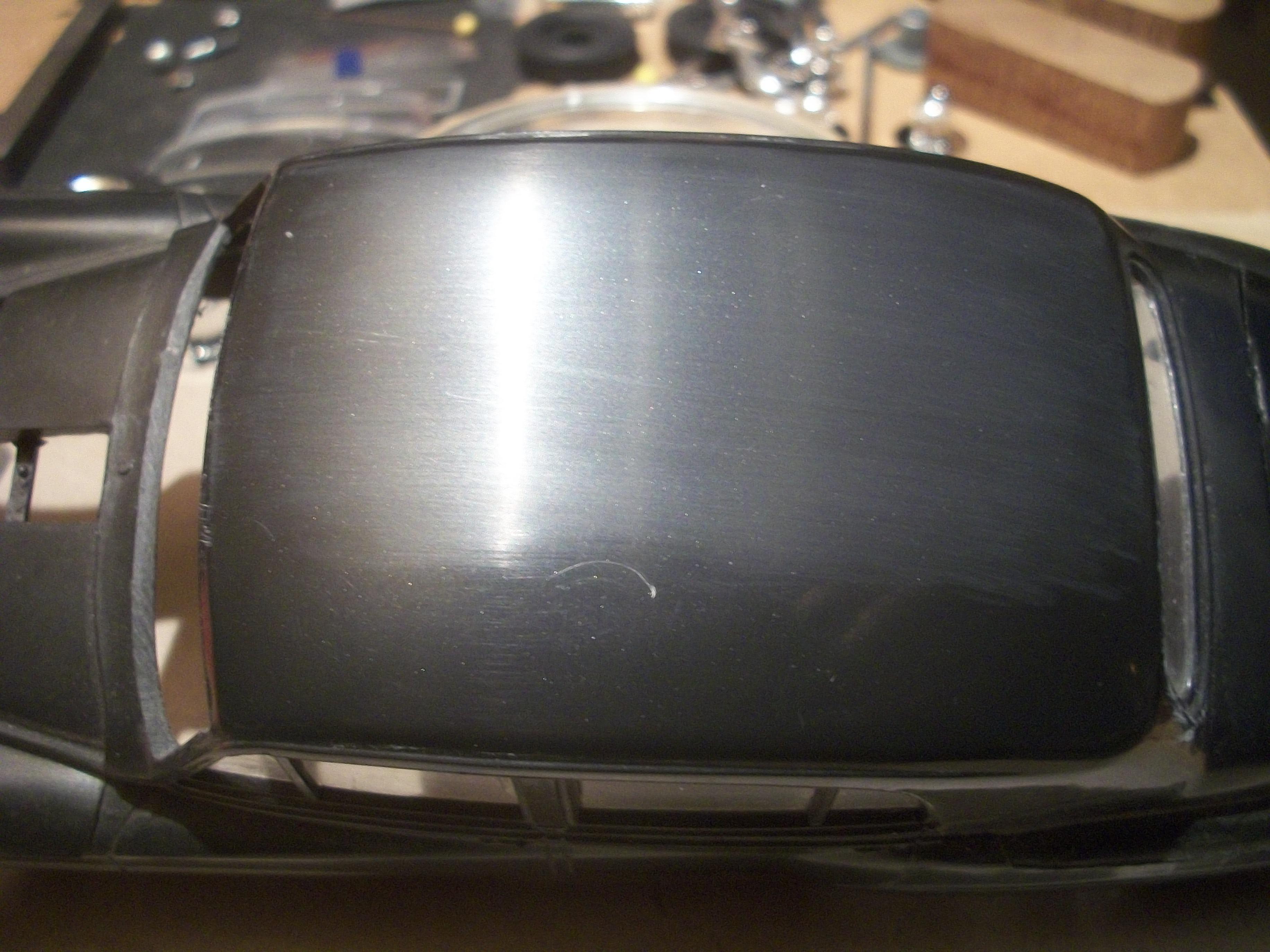
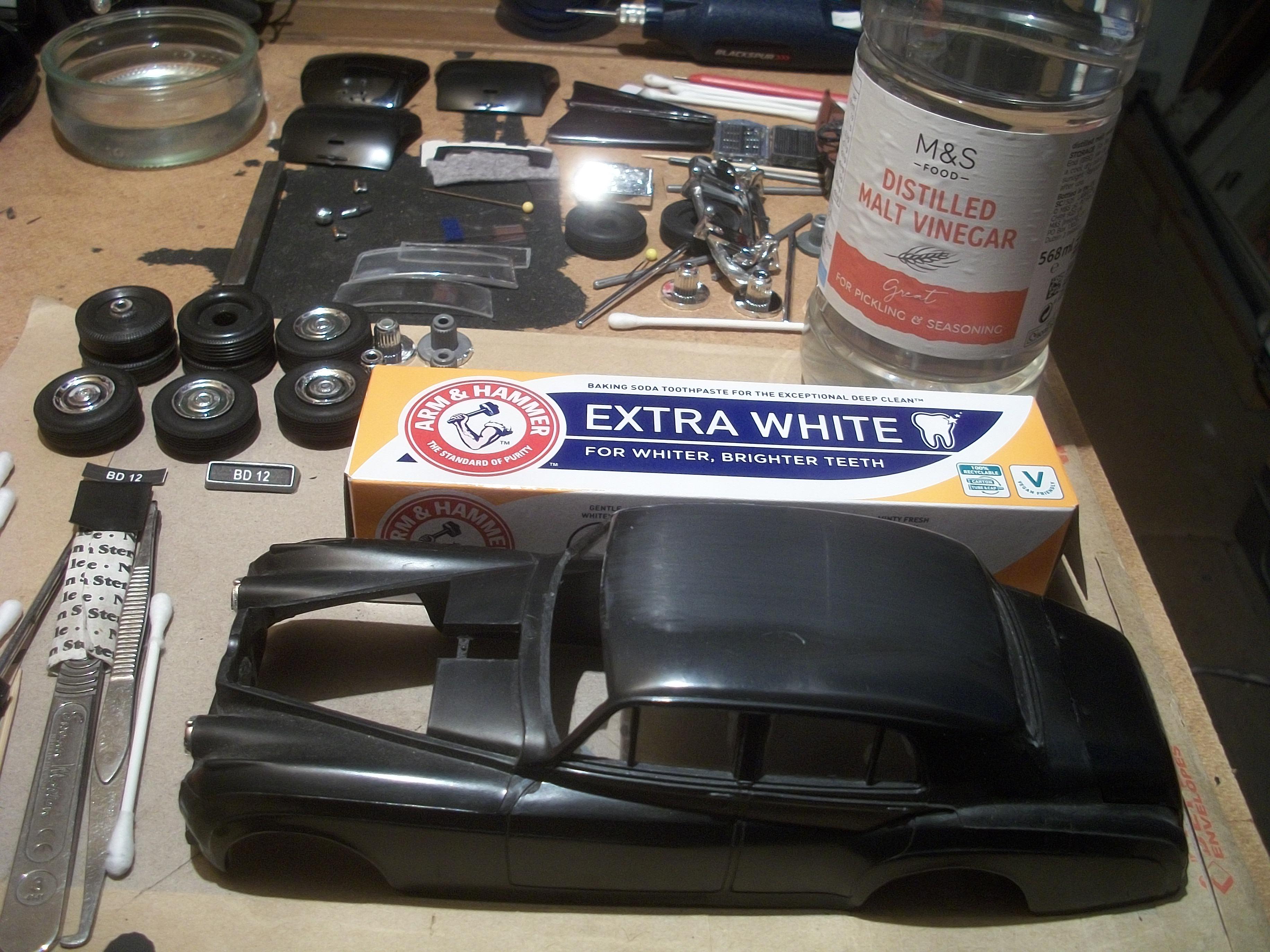
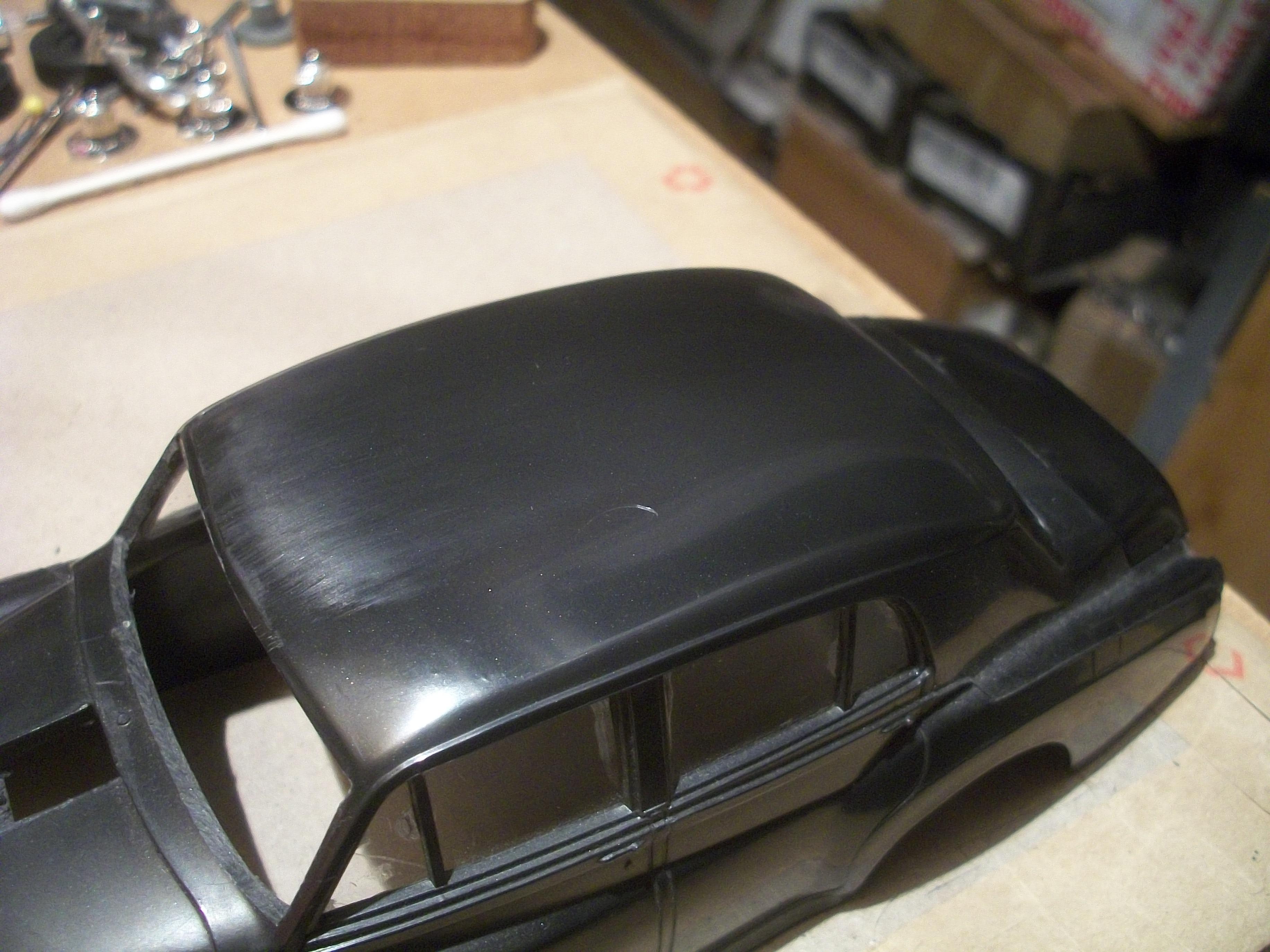
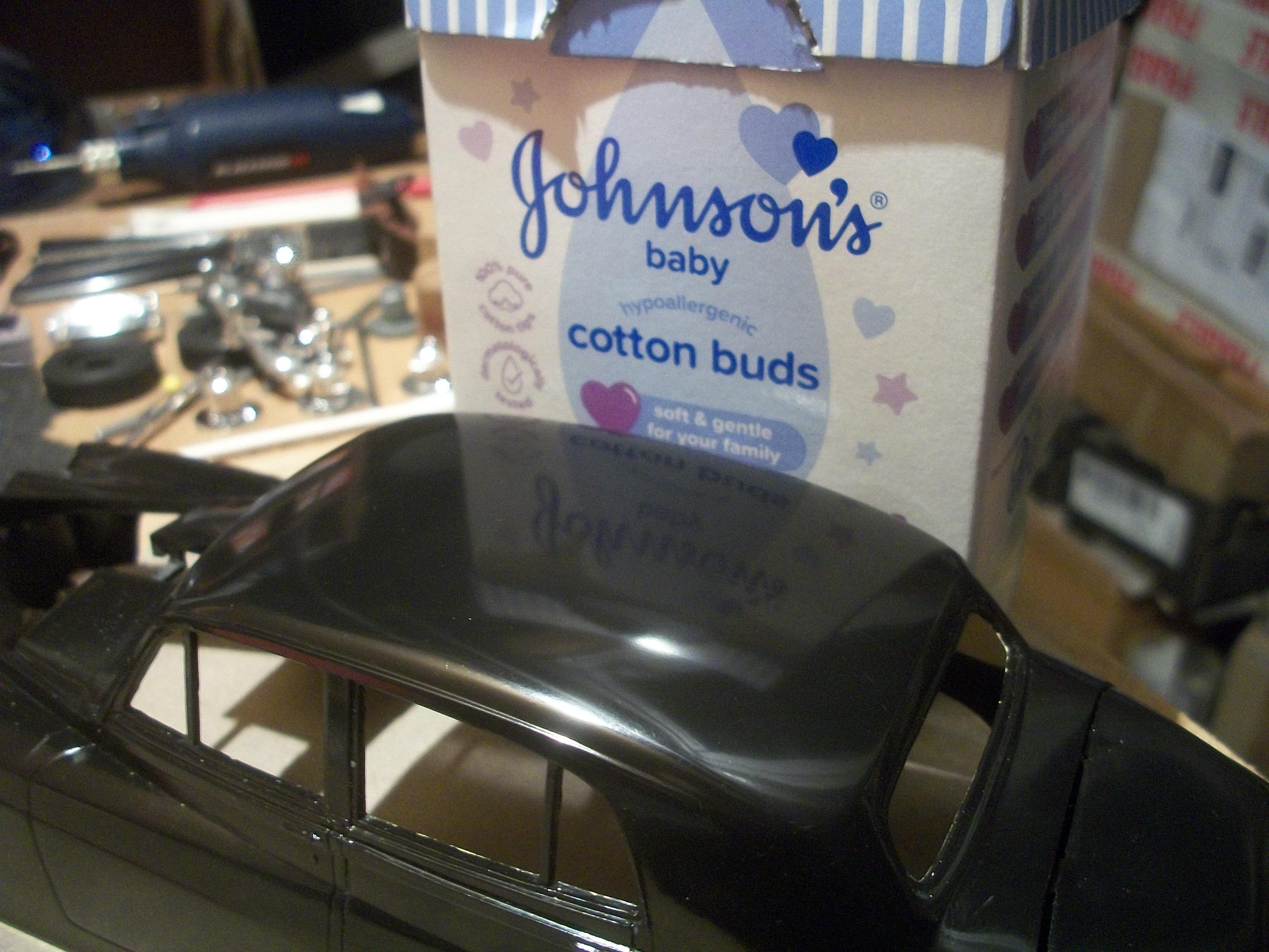
Previously I did try to add text to explain what I was doing in the photos, but the text was rejected, for reasons unknown to me. Basically, those photos showed an experiment to remove a scratch from the test body shell . . . Today I made some good progress with this process, this time using the Entex body that will be the actual build. Here is the explanation, along with some further photos. Hopefully my text will not be rejected this time, as it was quite a lengthy post and valuable model building time was wasted. First of all, a cross was drawn and cut out from a sheet of 2000 grit wet and dry paper. This cross was folded and placed onto the end of a length of square rod balsa, and held in place with double sided tape. Then I used this makeshift tool to sand the area of damage using some water. The scratch was removed and the roughness of the sanding process was polished out with baking soda toothpaste and distilled malt vinegar. I am surprised and very pleased with the result. This step forward has given me renewed optimism, which I needed greatly at this early stage. I intend to use a new silver Sharpie marker pen, and also some narrow art tape to produce a chrome effect on the rear door window frame. The area of damage that has now been fixed, was immediately behind the door window frame, near to the top rear corner. David
-
Rolls-Royce No Chemicals, No Paint, No Harmful Glues
Anglia105E replied to Anglia105E's topic in WIP: Model Cars
Okay Les, I will do thanks . . . I just removed a slash from between the two words " toothpaste " and " vinegar " David -
Rolls-Royce No Chemicals, No Paint, No Harmful Glues
Anglia105E replied to Anglia105E's topic in WIP: Model Cars
Yes Les, I had a feeling that it must be something contained within my text that was triggering off some sort of rejection. The trouble is, my text is quite lengthy in this case . . . Tried everything, but not only does the text not get uploaded but I get locked out, and cannot even access the MCM website . . . Used three different browsers, Opera, Edge and Chrome, but the problem continues ? David -
Rolls-Royce No Chemicals, No Paint, No Harmful Glues
Anglia105E replied to Anglia105E's topic in WIP: Model Cars
Thanks John . . . I am trying to upload the text that goes with these photos but MCM website will not allow me to do that ( error message is Oops that page can't be found ) -
Rolls-Royce No Chemicals, No Paint, No Harmful Glues
Anglia105E replied to Anglia105E's topic in WIP: Model Cars
Thanks Mark . . . I am trying to upload the text to go with these photos, but MCM website will not allow me to do that ( error message Oops that page can't be found -
Rolls-Royce No Chemicals, No Paint, No Harmful Glues
Anglia105E replied to Anglia105E's topic in WIP: Model Cars
-
Rolls-Royce No Chemicals, No Paint, No Harmful Glues
Anglia105E replied to Anglia105E's topic in WIP: Model Cars
Thanks Les, and I did consider cutting separate pieces of foil at first, which is how I would usually tackle this job. For some reason I settled on the one piece foil method, which has not gone well at all . . . David -
Rolls-Royce No Chemicals, No Paint, No Harmful Glues
Anglia105E replied to Anglia105E's topic in WIP: Model Cars
I found some sheets of 2000 grit wet & dry in my loft, so I will test this on one of the three body shells that I am not using for the build. Also, I will have a look at Albion Abrasives on Amazon as you suggest . . . David -
Rolls-Royce No Chemicals, No Paint, No Harmful Glues
Anglia105E replied to Anglia105E's topic in WIP: Model Cars
Yes John . . . That is something that I like, problem solving. Before I retired seven years ago now, I was a self employed technical support engineer, so working with all aspects of ' fixing computers ', both hardware and software . . . Each kit that I build these days leads me through a process of assembling the model and tackling every problem along the way. Such an absorbing hobby for that reason alone . . . Whenever I have purchased BMF over the past few years, this has been through Ebay sellers usually, so not directly from BMF and it does vary in quality. David -
Rolls-Royce No Chemicals, No Paint, No Harmful Glues
Anglia105E replied to Anglia105E's topic in WIP: Model Cars
Having watched the whole of the tutorial, start to finish and including the comments, I see this as a fascinating alternative to BMF ( and kitchen foil / PVA ). Some of the chemicals and the procedures are putting me off trying silver leaf very slightly. I did notice the water based size as an option. Personally, I have to admit to being rather clumsy, and especially with my hand movements ( hand to eye co-ordination ). You may ask why have I chosen to build scale model cars, mostly those that are smaller than say 1:12 scale ? . . . I have always been interested in everything to do with cars, and I have been interested in model cars since I was around 8 years of age. The very thought of me handling wafer thin silver leaf conjures up all sorts of nightmares ! David -
Rolls-Royce No Chemicals, No Paint, No Harmful Glues
Anglia105E replied to Anglia105E's topic in WIP: Model Cars
My narrow orange tape is 1/4 " in width, so if I can get hold of some 1/8 " or even 1/16 " wide tape that would be good . . . I do have chrome and silver Vallejo acrylic paints, which might go on nicely with the right brush. Thanks for the information and also the encouragement, which I do need at this stage ! David -
Rolls-Royce No Chemicals, No Paint, No Harmful Glues
Anglia105E replied to Anglia105E's topic in WIP: Model Cars
Thanks for the tips John, and I did try to get the cheapest kitchen foil that was available locally, but it could be too thick as you say . . . Certainly foil adhesion is the issue here mainly. I can have a look at silver leafing, and gather some information about that method . . . Now that would be entirely appropriate, silver leaf for a Rolls-Royce Silver Cloud ! David -
Rolls-Royce No Chemicals, No Paint, No Harmful Glues
Anglia105E replied to Anglia105E's topic in WIP: Model Cars
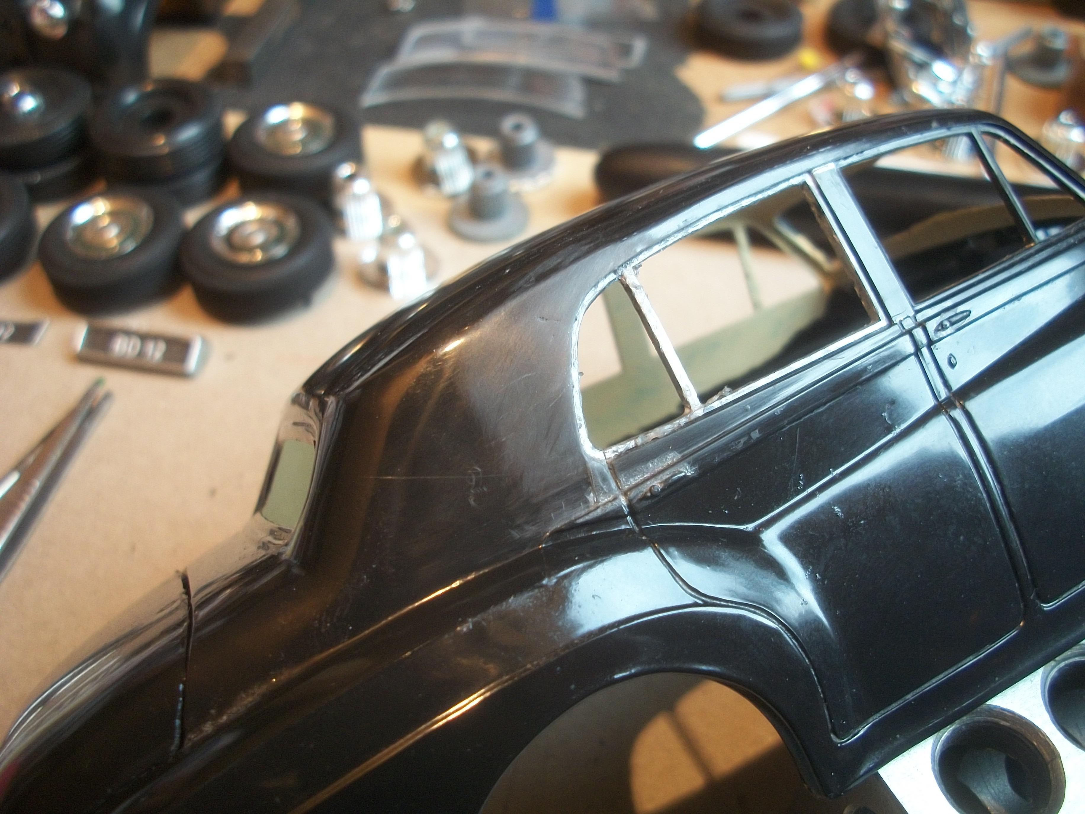
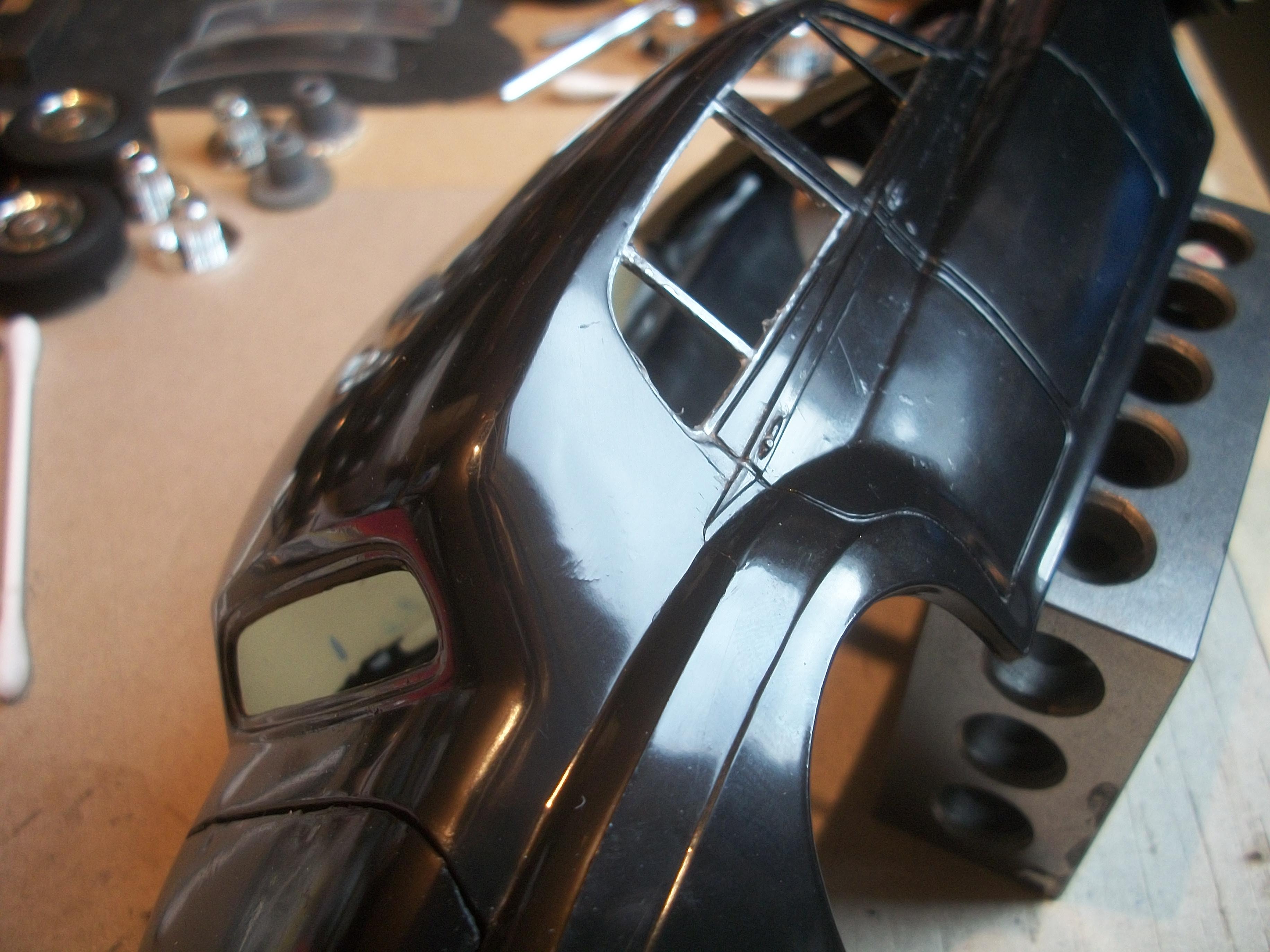
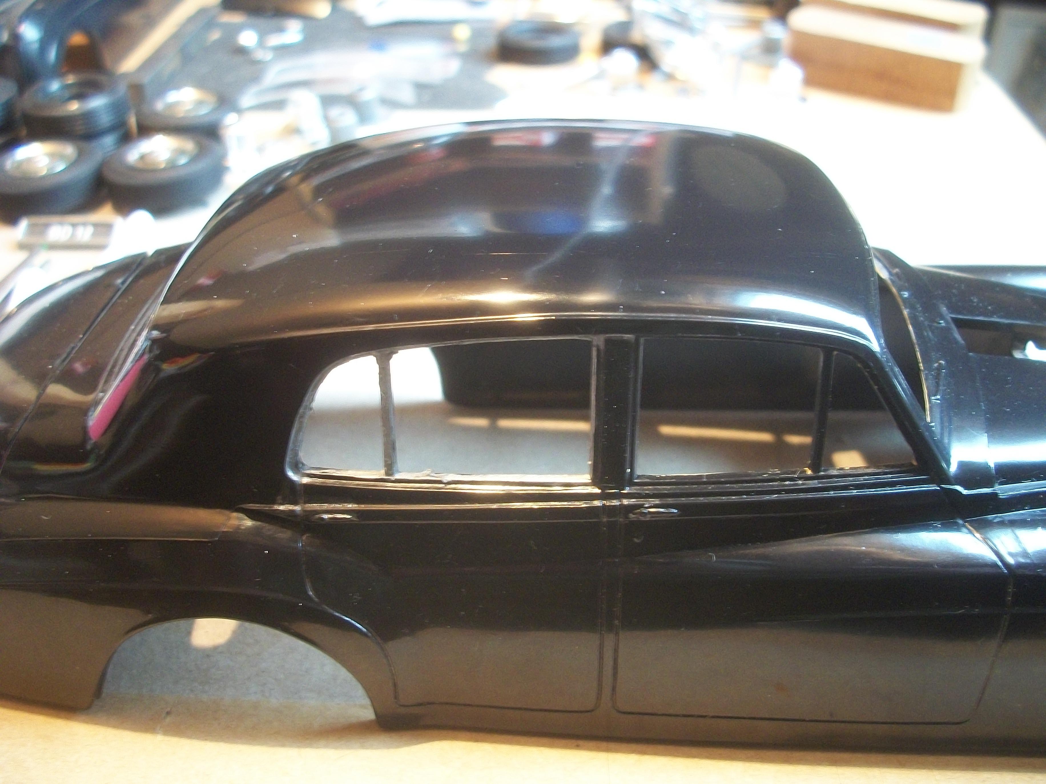
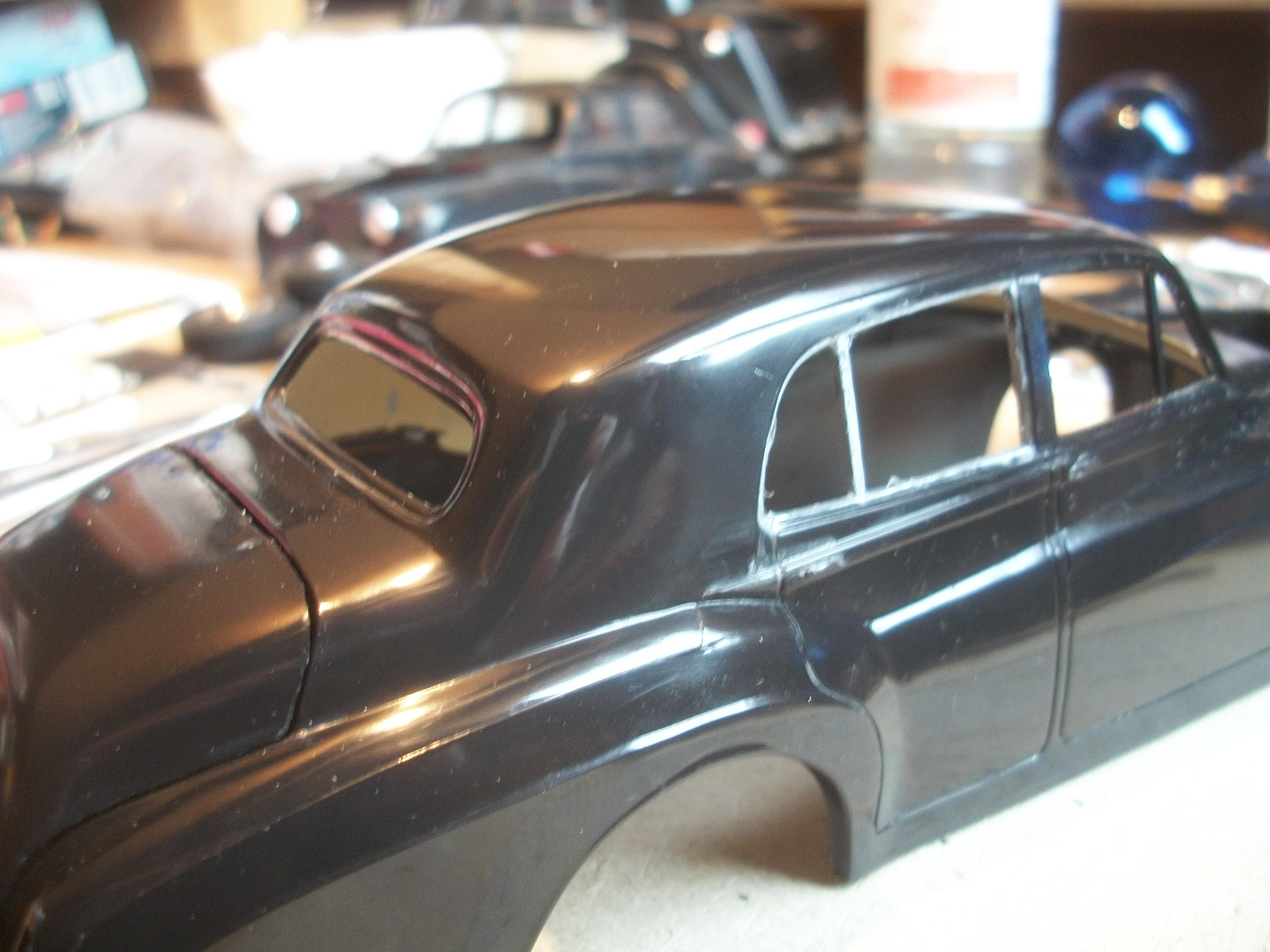
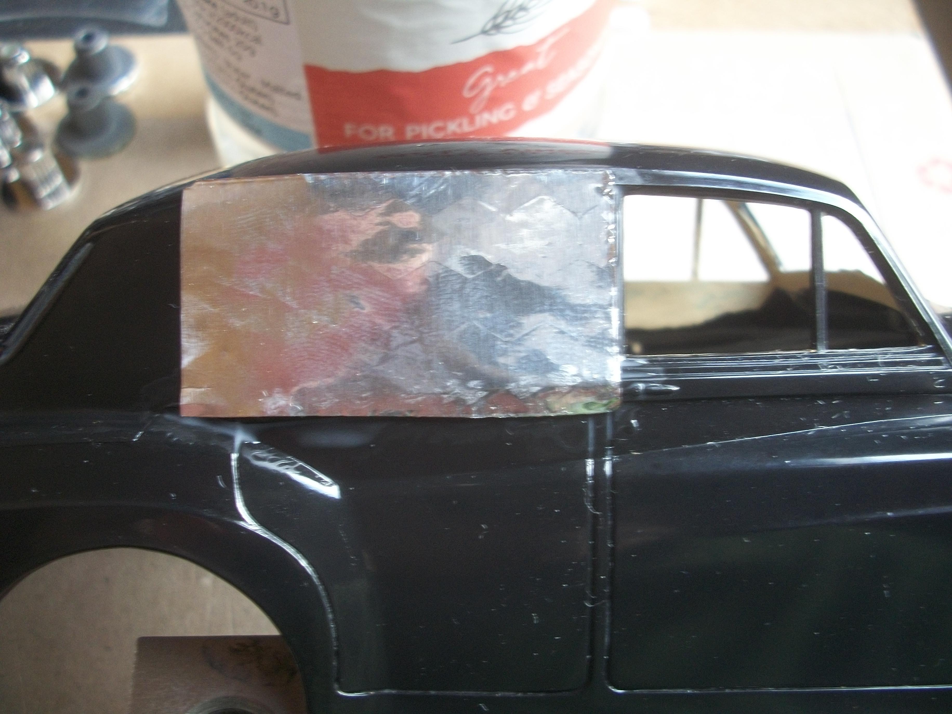
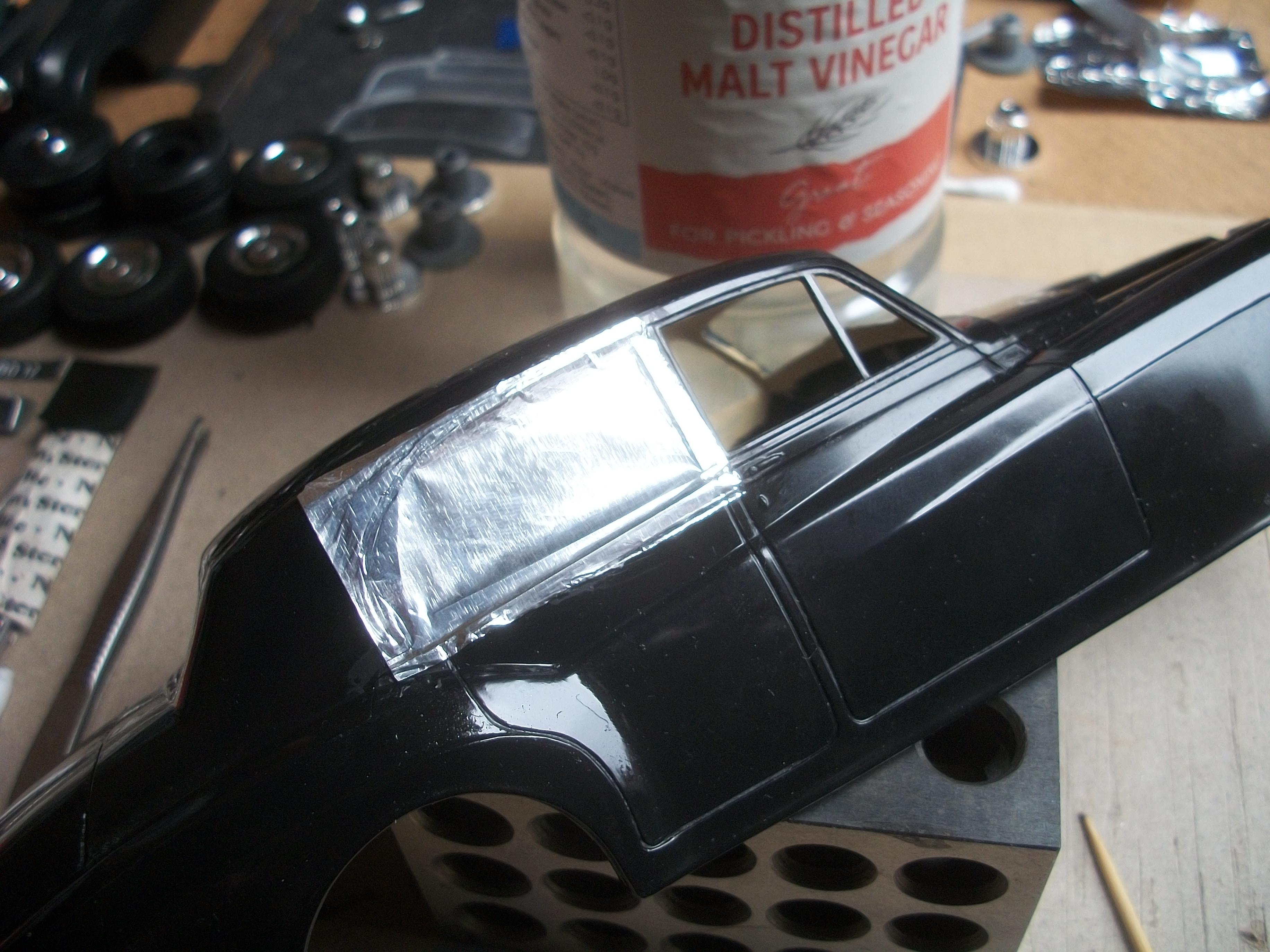
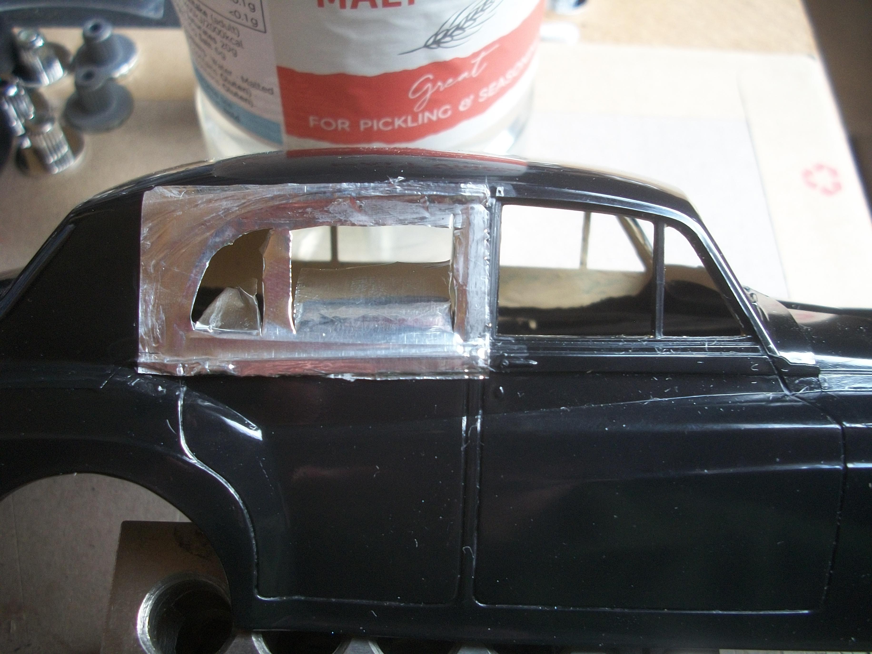
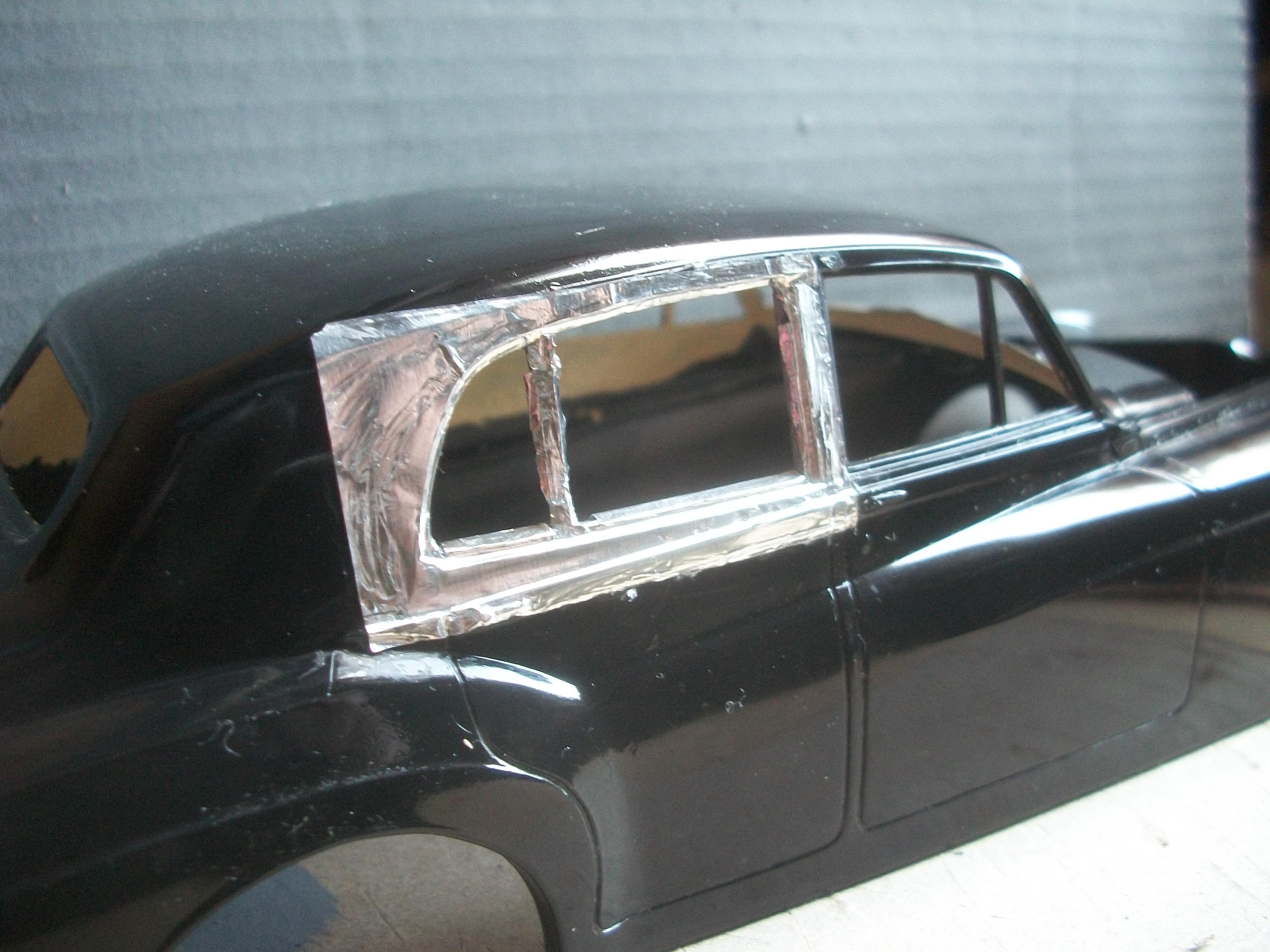
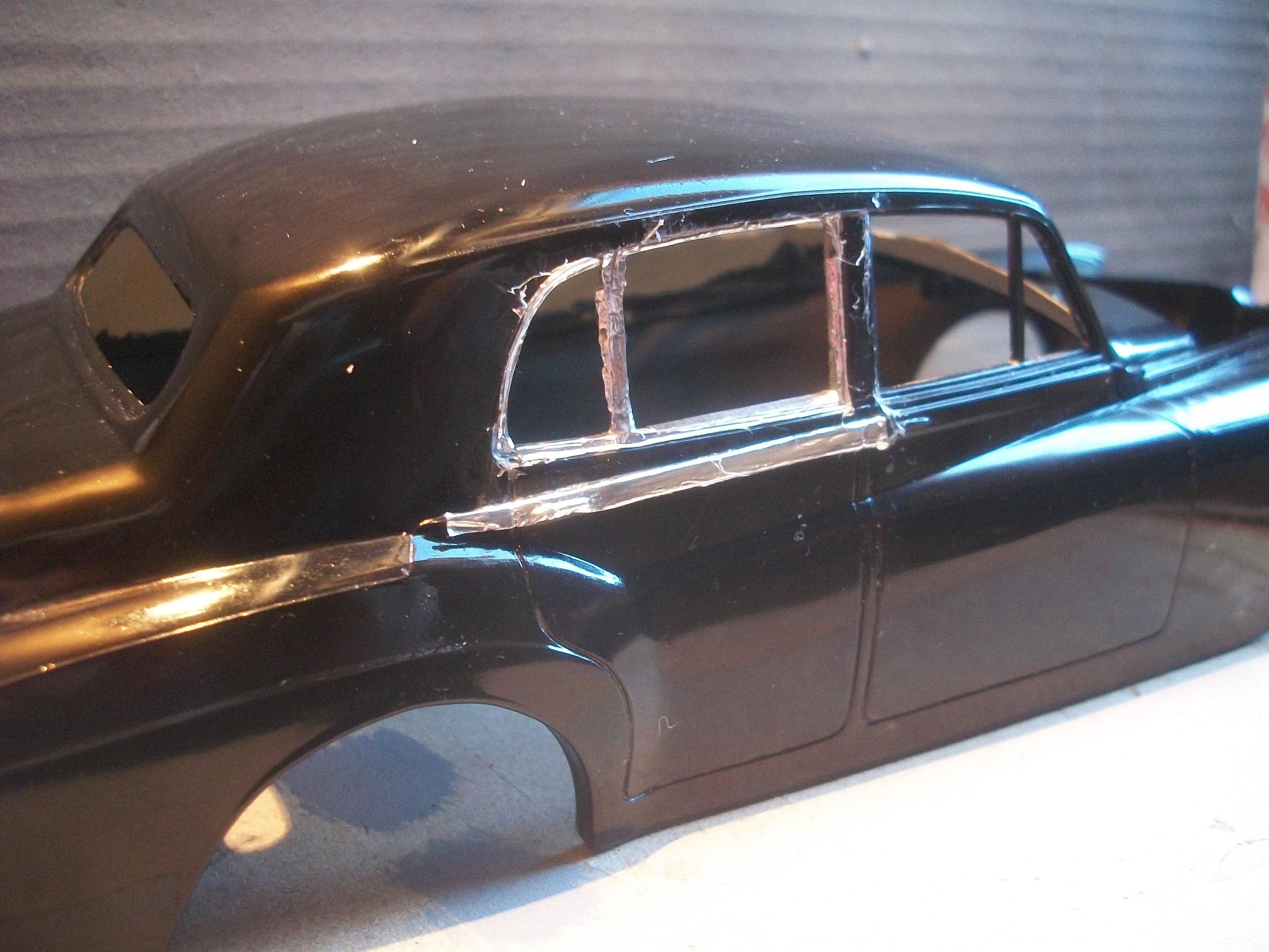
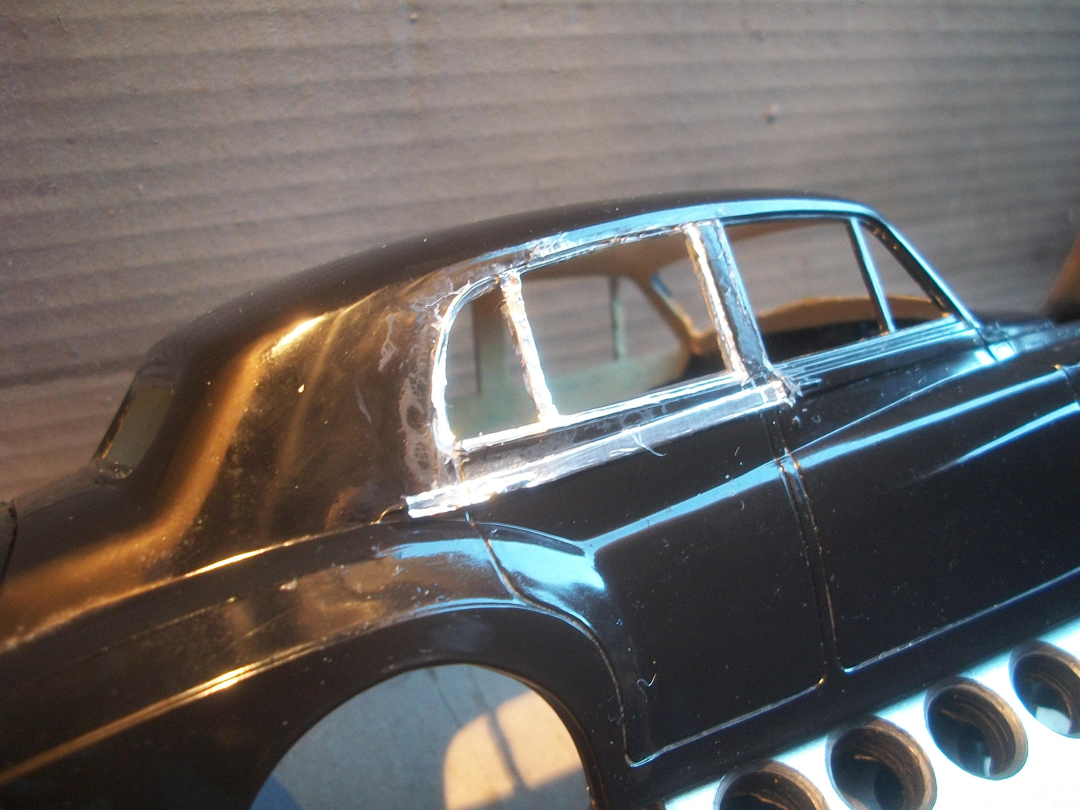
Today I attempted to apply chrome to the driver's side rear door window frame, which has turned out to be the worst bare metal foiling that I have ever seen. Although I say Bare Metal Foil, this was not done with the BMF product . . . I applied PVA glue around the window frame perimeter, and also inside the frame. Then I measured and cut out a rectangular piece of aluminium kitchen foil, 40 mm x 22 mm, and placed this over the window frame area . . . Leaving the foil to sit awhile, I returned later to cut away the centre portions of the foil with a scalpel knife. The edges were folded over onto the glued areas. Despite smoothing the foil carefully with a cotton bud and also the rounded end of a cocktail stick, the overall result is messy and ragged. I am not happy with the result . . . Just as you would expect a real 1:1 scale Rolls-Royce motor car to be presented with a high quality finish, my feeling is that a 1:24 scale model of this car should also be of the highest quality possible. I cannot accept this poor representation of chrome plating, so I need to rethink the whole approach to this build . . . Previously of course, Molotow Liquid Chrome would have been the product of choice for me, but I am not able to use this now due to my medical condition, and particularly with regard to the cleaning solution for the brush, i.e. Isopropyl Alcohol. I shall examine the body shell tomorrow morning after overnight drying, and maybe clean off the PVA residue to see if there is any improvement . . . David
-
Pyro 1931 Cadillac Sport Phaeton in 1/32 scale
Anglia105E replied to ismaelg's topic in WIP: Model Cars
Very nice colour combination, British Racing Green and Butternut Yellow ( almost cream ) . . . David -
Rolls-Royce No Chemicals, No Paint, No Harmful Glues
Anglia105E replied to Anglia105E's topic in WIP: Model Cars
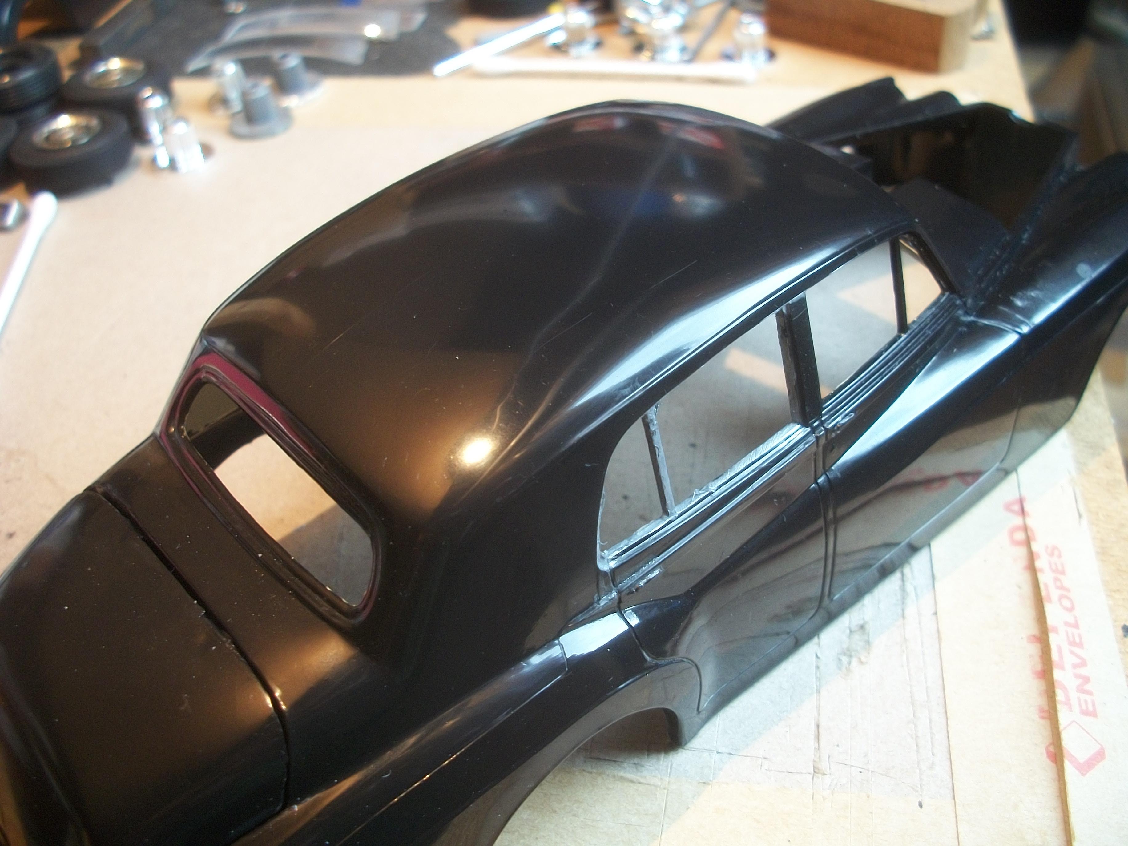
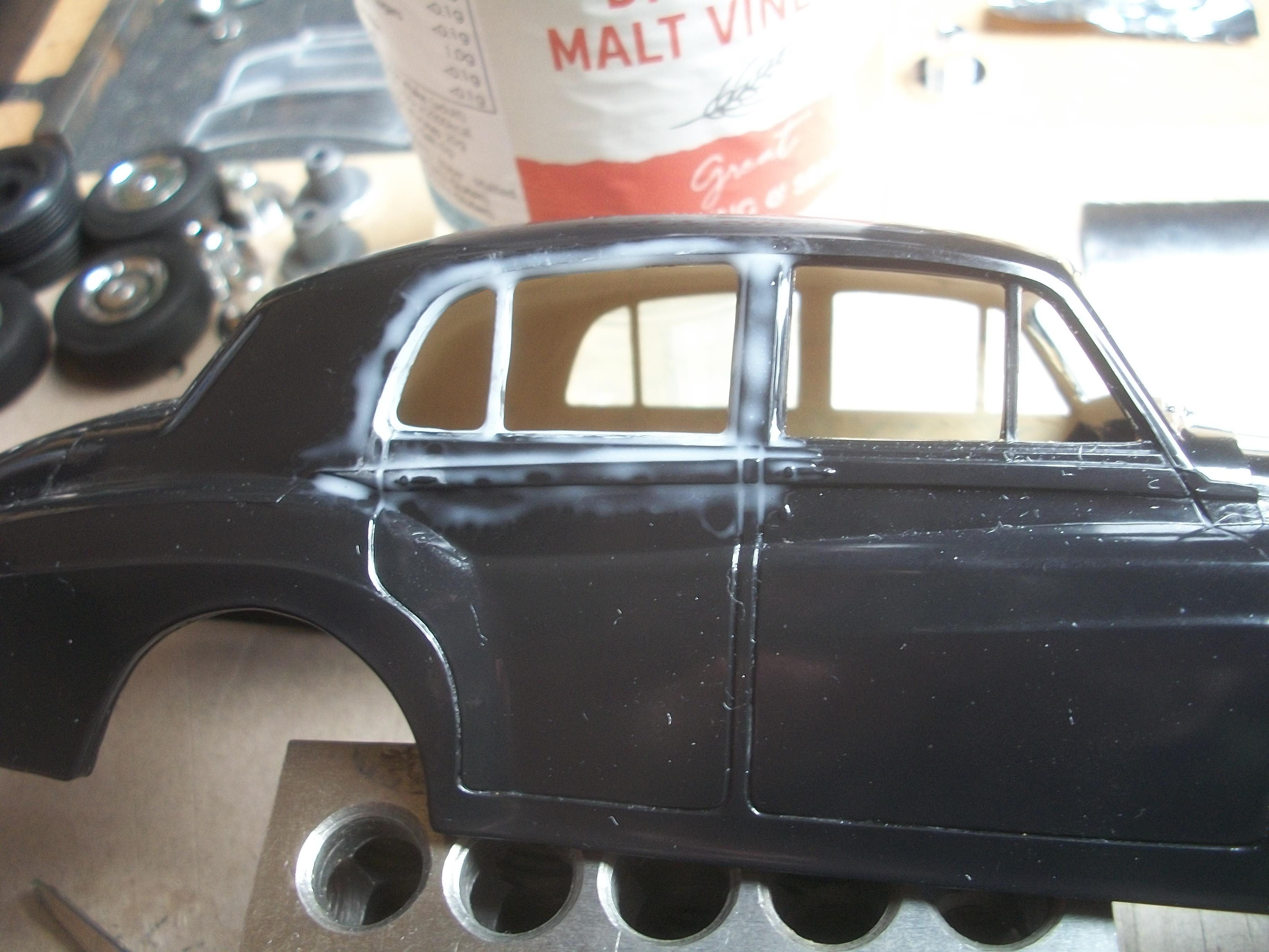
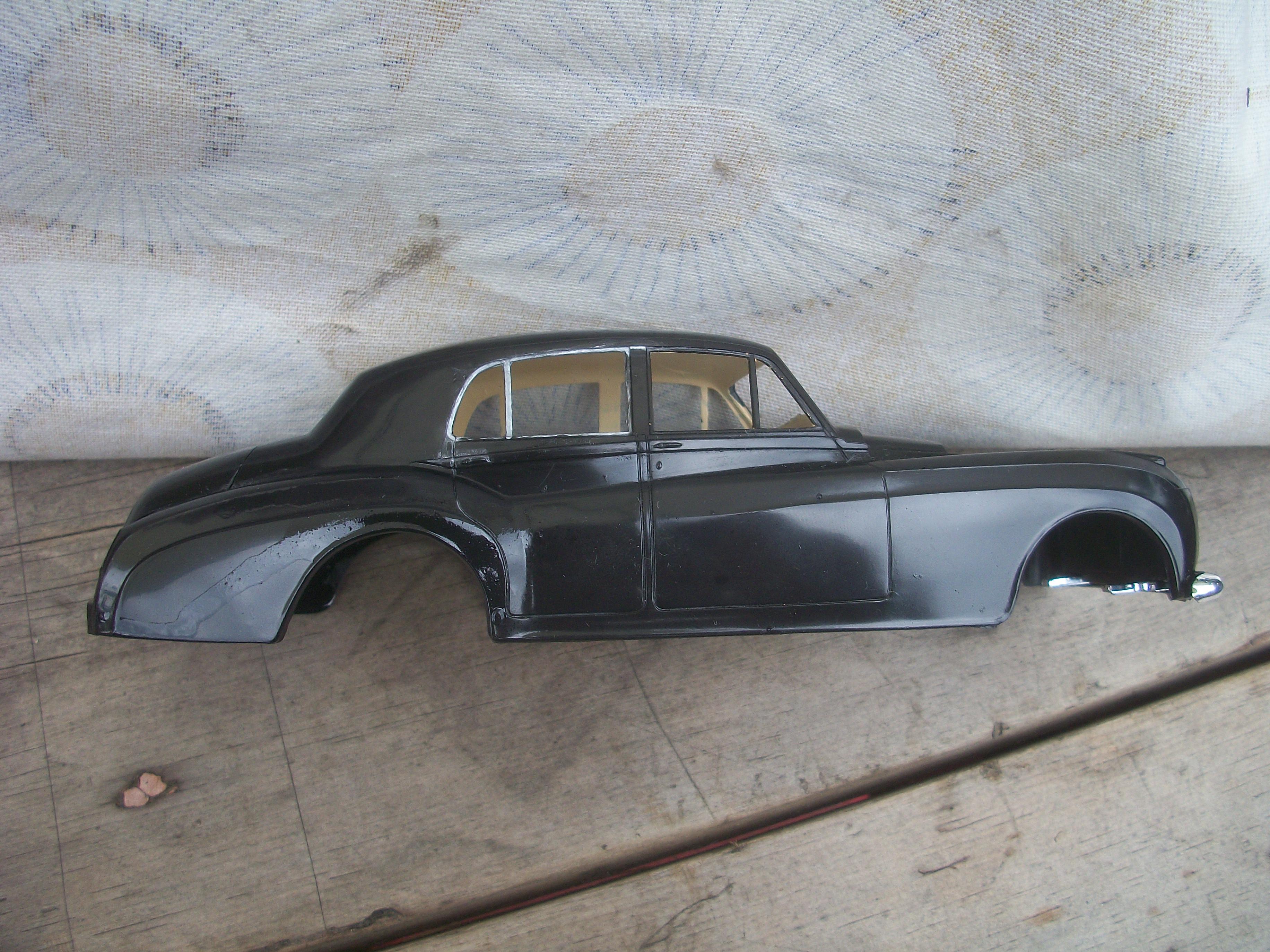
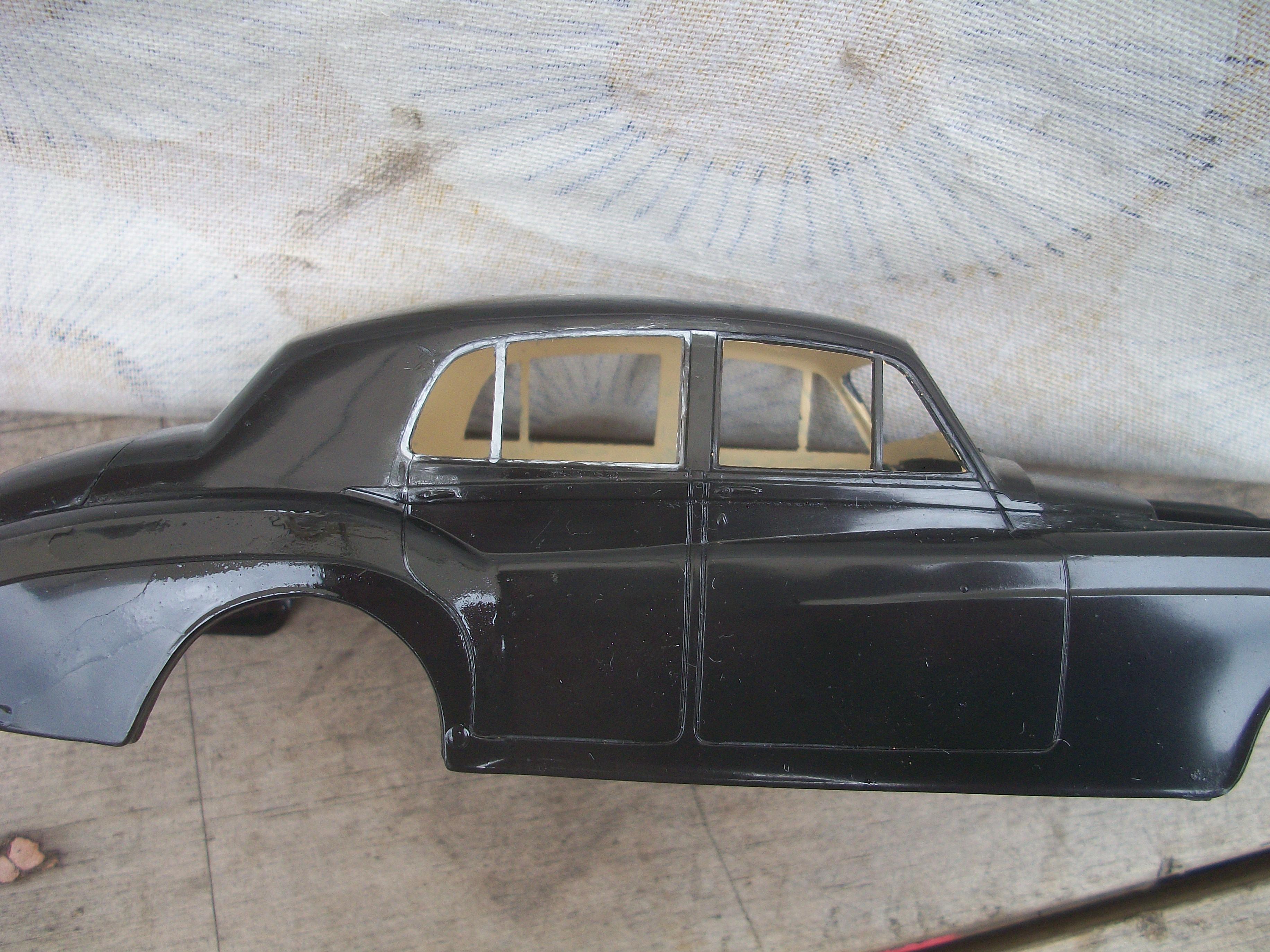
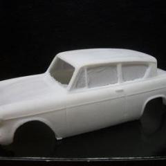
The following two photos show the Silver Cloud body after I have applied a small amount of WD40 spray. This was done outdoors, and then rubbed gently with a cotton bud . . . What I intend to do next is to use some kitchen foil and PVA glue to chrome the window frame of the rear door, and also to chrome the strip that runs along the side of the two doors, immediately below the windows . . . This will allow me to examine the area of the body shell that has been affected by the silver Sharpie spillage, and therefore to determine the overall appearance. David
-
Rolls-Royce No Chemicals, No Paint, No Harmful Glues
Anglia105E replied to Anglia105E's topic in WIP: Model Cars
Wow Mark . . . 6000 grit to 12000 grit is way finer grade than 1000 grit to 1200 grit !!! Not sure if my local supplier will have such fine grades in stock. -
Rolls-Royce No Chemicals, No Paint, No Harmful Glues
Anglia105E replied to Anglia105E's topic in WIP: Model Cars
Okay thanks Jose . . . Will get hold of some finer grades locally. -
Rolls-Royce No Chemicals, No Paint, No Harmful Glues
Anglia105E replied to Anglia105E's topic in WIP: Model Cars
Yes, I have 1200 grit wet & dry, and also 600 grit . . . -
Rolls-Royce No Chemicals, No Paint, No Harmful Glues
Anglia105E replied to Anglia105E's topic in WIP: Model Cars
Thanks Mark . . . Maybe someone can remember ? . . . I have used WD40 on the Sharpie mark today, and it worked quite well. I can try the wet & dry sanding paper with water on the roof scratch later. David -
Rolls-Royce No Chemicals, No Paint, No Harmful Glues
Anglia105E replied to Anglia105E's topic in WIP: Model Cars
I am a little nervous about using sandpaper and water on the body surface, but if this body shell is ruined anyway then I don't have anything to lose by at least giving it a try out . . . You are right about the Dremel, and in my case the Blackspur mini grinder, they do overheat the plastic pretty quickly ! David