absmiami
-
Posts
4,780 -
Joined
-
Last visited
Content Type
Profiles
Forums
Events
Gallery
Everything posted by absmiami
-
humidity ? what humidity ??
-
please take the next plane fight to south florida need someone to cleanup my workshop - bad ..... thank you
-
https://www.google.com/url?sa=i&url=https%3A%2F%2Fwww.conceptcarz.com%2Fview%2Fphoto%2F1608460%2C11284%2F1968-lotus-type-56_photo.aspx&psig=AOvVaw2SIt8z9LKafOFBfommxa3f&ust=1570054688554000&source=images&cd=vfe&ved=0CAkQjhxqFwoTCOjVw9OL_OQCFQAAAAAdAAAAABAc OK - not exactly a user friendly web link but find the Indy Museum display link at the Conceptcarz site .... 2 of the best shots of the turbine engine that I have ever seen
-
Autokits Lotus and Ferrari Trading Places ...
absmiami replied to absmiami's topic in WIP: Model Cars
http://www.peterhuttonillustrator.com/products/t-shirts and by the way - this illustrator has a T shirt with a terrific depiction of the car - engine bay forward gotta wear this while building, right ?? -
Autokits Lotus and Ferrari Trading Places ...
absmiami replied to absmiami's topic in WIP: Model Cars
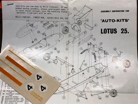
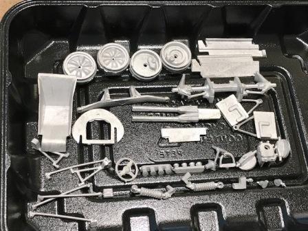
this is the white metal Louts 25 kit - which will be the basis of the Lotus 32B build plan to use a small portion of the lower body and a part of the upper body plus some of the misc wh metal parts - like the suspension uprights and the wheels the tires - by the way - are not bad - but I will source some Dunlops with proper tread pattern detail
-
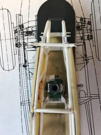
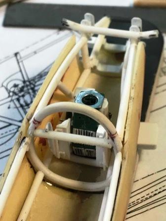
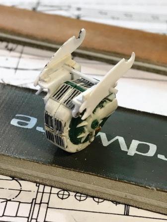
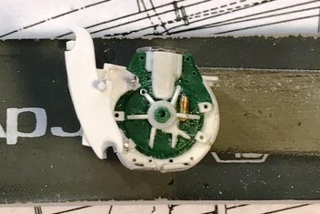
so the braces will be attached to the frame as shown its close to how the real engine is braced - the difference is that on the real car the two vertical braces are a bit closer together but this will do - and I've got it measured so that the engine sits at the correct height and tilts back a bit - like it is supposed to .....
-
the engine has to be attached to the frame in order to do this, I needed to make the braces that hold the engine these were cut from .015 evergreen strips and glued together with liquid glue seven pieces in total - the structure can be removed as a unit for painting/finishing ....
-
rare bird
-
Mr W thanks for being stubborn will enjoy this and remember: technology is your friend .... until it’s not
-
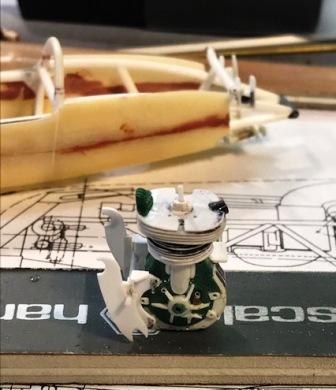
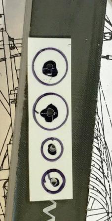
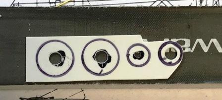
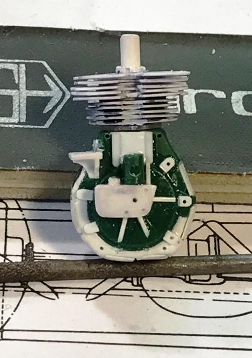
the Merit kit engine had a partial crank case that sat on a cradle of plastic at the bottom of the shell once I made a full crank case and ground away the "cradle" - I had to duplicate as best as I could - the brackets and braces that the engine is attached to .... that's what these pix show ..... this is tricky - because the engine must have good attachment points and tilt back at a slight angle and when all the parts are fitted to the basic crank case and cyl head - the engine bay will be crowded .... so I have to judge part scale from photos - without the benefit of detailed frame drawings there are detailed cutaways - so I judge the relative size of the components from photos and these drawings which is partly why I'll have to re-do a number of parts more than once .... pain ....
-
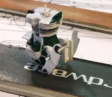
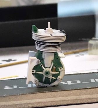
cylinder head - "aches" while making the brackets that cradle the crankcase and attach to the frame braces I noticed that the engine was too short .... 1026 has the cyl head that I made a month ago - if I use that - the amal carb does not protrude over the lip of the engine cover opening so to get the carb out in the airstream, where it belongs - I made a couple more rows of fins - per 1104 since I had not glued the cyl head on to the crank case - I just glued two more fins to the bottom of the cyl head note to me - got to get a hole punch set for larger holes - would have made this much easier .....
-
my bad you open the box that says Reply to this topic at the bottom of the box you will see a prompt that says Drag files .... or Choose files - that's the one that I use ...
-
hi Tom once you sign in - that's the hard part - remembering your password ...... once you sign in and click on the comment box - it should open with a small blue underlined prompt that says "choose files" click on that prompt and then download a photo from your computer and away you go I don't use the drag files feature - probably easier - but I'm still relatively clueless ..... and I like the project idea ....
-
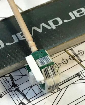
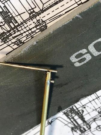
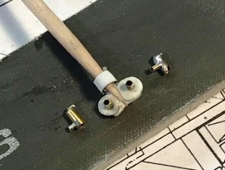
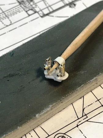
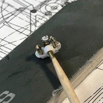
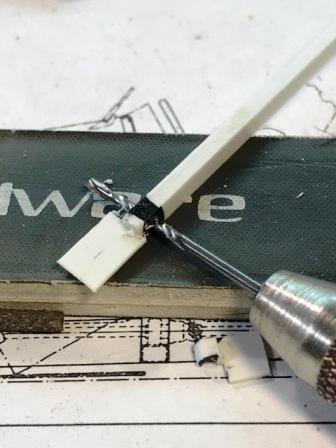
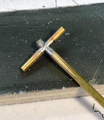
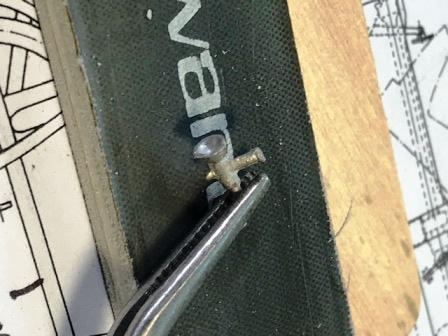
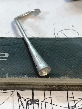
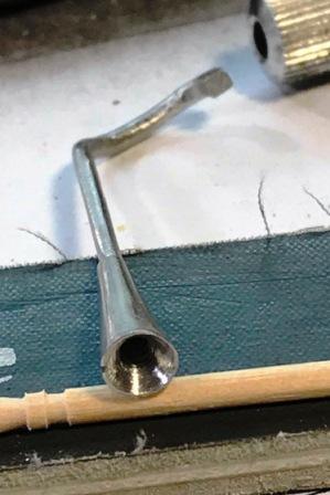
making the float chambers that flank the Amal carb and the tray that they are fixed on its unusual to run a double float chamber setup - but I think that a few of the FIII coopers used this including the one that I making I need two fittings on each chamber for lines in and out the first two pix give you the idea - but this on was too tall and wasn't used the trick is to solder one fitting and then clamp it against the tube so that you can then solder the second fitting without damaging the first solder joint ... this is the skill that Randy D has nailed ..... made a couple more that were the correct height - one is sharper than the other but I'll probably use them both neat trick dept ; you can grasp a long tube while your making a part by removing the other half of your pin vise why didn't someone tell me this ????
-
Autokits Lotus and Ferrari Trading Places ...
absmiami replied to absmiami's topic in WIP: Model Cars
has anyone tried construction of these kits with low temp solder ?? -
Autokits Lotus and Ferrari Trading Places ...
absmiami replied to absmiami's topic in WIP: Model Cars
wouldn't mind seeing a picture of the built model I've seen most of the kits built - but not this one .... did you build the Bugatti 35 kit ?? reminds me - the Ferrari kit has those same wheels - with the soft wire and the notched rims ... -
Autokits Lotus and Ferrari Trading Places ...
absmiami replied to absmiami's topic in WIP: Model Cars
the best tech description of the frame is in Whitelock's book on the 1 1/2 litre formula the frame rail diameter is 1 1/2 inches - I'll bet that the Exoto's frame rails are over-scale .... -
Autokits Lotus and Ferrari Trading Places ...
absmiami replied to absmiami's topic in WIP: Model Cars
thing 3b frame was probably scale 1 1/2 inch dia - not sure most of the frame members run straight - so you can use either brass or plastic thing 4 - go to town on the clutch housing - do you own a lathe ? if not - there is a plan B .... -
Autokits Lotus and Ferrari Trading Places ...
absmiami replied to absmiami's topic in WIP: Model Cars
thoughts: three things to make a better mousetrap than the Exoto ... thing 1: does the Auto-kit have photo-etched inserts for the wheels ? can't remember thing 2: how are the kit exhausts ? got some ideas if they are as bad as the Exoto ... thing 3: the frame members look over-scale on the Exoto - Do you have Jonathan Thompson's scale drawings ?? -
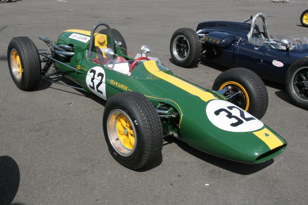
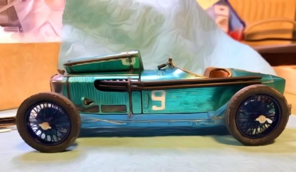
Now I've done it Long, long, long ago I traded one of my 24th scale Autokits - the Ferrari 156 - to Forum member Rich C for his Autokits Lotus 25 and neither one of us has built them! these are the old curbside white metal kits that are now made by Finecast they build up great as curbsides so I thought - why not have a build blog for both we'll post as we can - and hopefully two builds will take shape as we go - the Ferrari constructed in the leafy confines of Sayre Pa. , and the Lotus constructed in the alligator infested swamps of South Florida .... as to my kit; I'm considering building a Lotus 32B - using some of the kit parts, such as the top half of the body, the wheels, uprights, and a few more random parts - I'll scratch-build the monocoque chassis and the engine - which was a four cyl Climax. The 32 B was based upon the Lotus 27. It had a slightly narrower chassis (than the 25) and straight runs of chassis rails - rather than the bends and kinks used on the 25's chassis. It looked like a Lotus 25 with a climax engine - but in fact it was not - but its only about an inch/half narrower than the 25 so I think I can finesse this .... this shot is from the Ultimatecarpage.com site hope Mr. Ultimate has no objection I'll remove this if requested but in the meantime - this gives you a good idea also there is a wonderful illustration of the car at PeterHuttonillustrator.com for those not familiar with the car, Google history of the Tasman racing series and you'll be an instant expert ...... this was one of Jimmy's favorites .... Rich will introduce his Ferrari ....
-
Cooper barn find
absmiami replied to absmiami's topic in WIP: Other Racing: Road Racing, Land Speed Racers
OK - here we go ... gonna start a new topic for our foolish adventure .... -
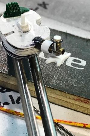
the bracket is made from Evergreen plastic sheet the float chambers will look like the float chambers seen with other carbs making those in brass - I need some strength because fuel lines will be running in and out of these chambers ... the small size of these components prevents me from making a plastic part with adequate strength to attach the fuel lines ...
-
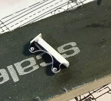
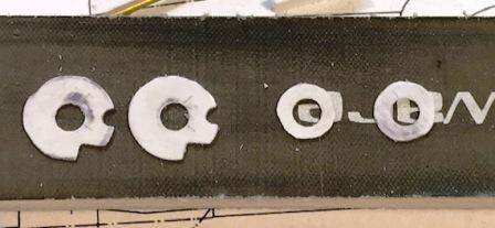
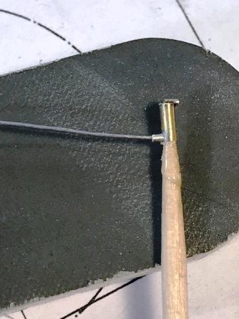
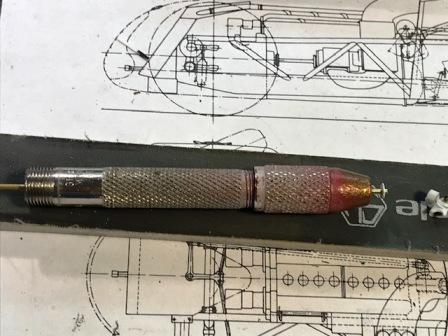
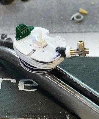
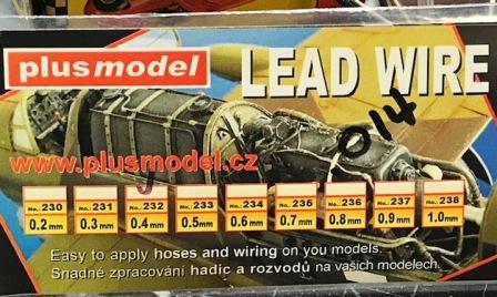
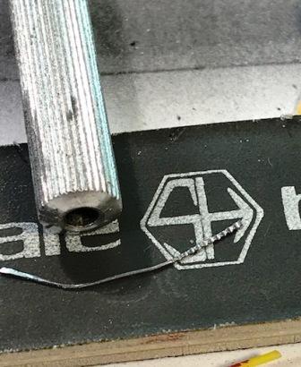
there are a number of websites that have good drawings and pictures of this particular carbureter, which is an Amal T.T. One that I used is www.stevenott.com. the soldered brass is .051 thinwall and .060 thinwall, with some bits of evergreen plastic for some of the detail features. the cap was made be rolling a hand tool over some 0.014 soft lead wire, and then gluing a short length around the top pf the primary - or mixing - chamber of the carb, to duplicate the cap ... still have to machine an aluminum intake tube - that will be done later the carb is flanked by two float chambers, that sit in a bracket hung from the shaft of the carb intake .....
-
the cast white metal carburetor was not so useful - the original Merit casting in plastic was merely a sort of suggestion of what an Amal carb actually looks like and it sticks up and out of the top of the engine bay - it will be the first feature of the engine that you will see - so I'm making my own .....
-
the Herb Deeks kit - which I referenced in the Cooper Barn find blog - recast some of the Merit kit parts in white metal which gives me a great looking exhaust pipe - just had to clean it up and open the exhaust megaphone .....