
fractalign
-
Posts
851 -
Joined
-
Last visited
Content Type
Profiles
Forums
Events
Gallery
Everything posted by fractalign
-
This is what the jig will eventually look like. With all the contour gauges finished I will be able to get both body sides to be the same.
-
Because I have made this panel removable, I will be able to construct the engine bay, once the floor and firewall are completed.
-
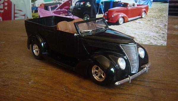
This is how it looks sitting in the jig. You will notice the contour gauge in the back ground that will eventually attach to this assembly, once I have cut the other three to match it. This is what will make it a cradle jig. The other part in the foreground, slots in at the front to support the hood. This panel will actually hold the whole body in place while I work out the rest of the floor and firewall.
-
Hey Guys. Sorry for not posting anything yesterday, I was pre occupied with a minor drama of sorts. Anyway back to build and more work to the jig. This time I joined the cross beams.
-
This gets 10 out 10 for originality in my books !
-
Here is the floor sitting inside. The top of the jig and the floor are the same width. Like the front, the rear of the jig will have wheel arches attached as well. These will also act as bucks so that the fenders can have the lips shaped properly. Once the jig is finished then I can really get back into getting the body finished so getting this jig completed will be the top priority in the next couple of days. Having said that now that I have the front arches made up on the jig I can also start shaping the front wheel arches too. So getting these two things completed will be the next tasks.
-
At the moment I have glued the driver's side body and the hood together. I have done this so that I can get an idea of how the other body side will fit. You will notice that two of the slats have a strip of 2mm thick styrene inserted. These will have templates added to the ends that follow the contour of the body sides. These additions will make this a cradle jig that actually suspends the body above the main part of the jig. The reason for this is to allow enough space for the floor to be able to sit evenly inside the body. The floor will be removed and put back in when ever the new panels are added and with the body suspended above, this will be a lot easier to do. I will be using the same principal for when I do the firewall and rear cargo area.
-
I added the centre shaft to stop the sides from falling into the centre of the jig. I may add a higher shaft to allow the body to rest from underneath the hood.
-
Hey Guys. Thanks for all the positive feedback and tips. And yes Niko, i will eventually cast it because I want to do a few different builds. As far as the putty goes I only use it for surface finishing. Any structural filling is done with car bog. Anyway apologies are in order for not putting anything up yesterday, I have been feeling run down all week. I am getting back into a normal state now so I managed to get some more done today. In my last post I said I would continue working g on the body sides including the wheel arches. In order to get both sides symmetrical I have gone beck to work on the jig. I mentioned some time back that I was putting a jig together and even though it is not actually part of the model, it is still integral to the build and unfortunately with out it the build will not continue. So here is what I did. The arches at the front are for the wheel wells. The body will sit over the top.
-
Its all looking very impressive so far but if you come unstuck at there rear window I have a suggestion. You could reverse engineer the window. By that I mean instead of cutting out and then carving the window, you would create a die or mould for the window. First you would measure the inside window area on your 1:1 coupe and then scale the measurements down. With the measurements you would create two templates. The first would be the inner template, that is the actual window opening itself. The second or the outer template would be perhaps 1mm larger. This one would be for the beauty line that follows the contour of the window opening. Once glued together these two templates would form the die or mould to create the actual window. It works best as press mould, I used Fimo for my door frames on my 34 Chevrolet utility. Fimo is a baking clay that when set can be sanded or glued to take on the characteristics of plastic. You will notice in the image of my ute model that the belt line actually dips down in the centre along the door. This belt line would have been almost impossible for me to recreate if i had not created the mould for it first.
-
 Thanks for the Harald. But I think I have enough my self.
 -
Hey George. The Thirties were indeed a golden age for truck design. It was the birth of the big rig with makes such as Faogel the forerunner to Peterbilt, Federal, Kenworth and Diamond T all building ever larger trucks. The first truly modern semi trailer based trucks all evolved from this era.
-
I will be continuing on with the bodysides until they are complete before moving back into doing the floor pan. The next task will be to add the lips to the wheel arches and get the belt line and seam line finished on the other side.
-
After sanding this is how it looks.
-
Here is how it all looks. The crease line is more pronounced thanks to the better properties of the putty, its bit more expensive but worth every cent. The square tubing is attached and the white putty had been layed along the sides.
-
With the putty layed on, the square tubing was placed in position.
-
The square tubing is for the belt line that runs along the length of the body and the putty is for the the side body contour. The original belt line I was going to use was half round but because the actual belt line on the 1:1 car has a flat surface, I decided to use the square tubing instead. The tubing measures 1mm by 1mm. The white putty is the best putty money can buy in my opinion. Nothing else comes close in terms of finish, while other putties are sticky and often melt into the plastic this particular putty sets more like cement. The whole side was covered so that I could finally finish off the crease line.
-
Hey Guys. I am back into the build once again after a one week break. While away I picked up some supplies. Some evergreen 0.40 X 0.40 solid square tubing and white putty. I was supposed to continue working on the floor pan but I decided that the body needed refining. I wasn't really happy with the seam line or belt line so they had to go.
-
Thanks for the info !
-
So what you are saying is that I should modify the BB axel that I am using for the 32 and 34 truck and use it instead, if thats the case, I will do that instead. Cheers.
-
The other thing I did was add some half round to the base of the wish bone, the other side is yet to be done. The axel now looks like a proper truck axel and not a pickup axel. Sorry there are no more photo's but I have been flat out packing today because I am going a way for a week or so. When I return I should have a fresh batch of model building material so that i can really get back into the build. Cheers.
-
Hey Guys. A long over due update on the project, I have been preoccupied with another build but I took time out from it to work on the truck, namely the front end. In the last post I was unsure if I was going to use the kit axle because it was a little narrow. Well I solved the problem. First I cut each stub axle off. Taking some thick plastic tubing, sprue, I cut to lengths and glued them onto each end and then reattached the stub axels. The fit axel to did not have these pivot points, so in real live this axel would not steer. With the stub axels corrected, I drilled holes in each one. The steering brackets will attach to these.
-
Hey Guys. Thanks for all the positive comments, but I am just letting everyone know that the build will be on hold for the next week or so. I am off for a week but while away I will be getting some new supplies for the build, there is a very good model shop near where I am staying so that I can can straight back in to the build when I get home. Cheers.
-
One thing that many modellers overlook is the accuracy of the kit its self, I can't speak for all kits but I know that many pre 49 kits have flaws in either the body, suspension, wheels or chassis. Take the Revell 41 Willys, The Pro Street Version, Jason mentioned the raised perimeter around the front windscreen that modellers often forget to paint, thats easily remedied with a bit of common sense but there a few other issues around the kit that need addressing. Don't get me wrong there is no doubting its a nice kit, I even own a couple but if you look at the front wheels you will notice that inside wall of the tyre is thicker than the outside wall. What that translates to is the fact that the front wheels are far too small for the kit. If you were to scale those wheels up to 1:1 they would probably only be 11 or 12 inch diameter. Because the front wheels are so small the stance does not look right, it appears to actually sit too high at the front, it doesn't really but the small wheels do not fill out the fender wells properly. Here is how I remedied that problem. The front wheels are from the AMT 41 Ford Woodie. They are actually more of a match for the rear wheels then the kit versions were. The Revell 32 Ford Highboy is another example of a nice kit. Its a traditional build with big'n little Halibrands and a multi louvered hood but there are just two problems, and these are in the body. Traditional highboys have shaved doors, no handles and they have stock hinges. The revell kit has the opposite. I can't recall the number of times a builder has gone for a period correct 40's or 50's build sourcing the right wheel tyre combination, suspension, and drivetrain only to over look this important detail. Another area where all the Revell 32's suffer can be found in the chassis. When Revell tooled up this kit they overlooked one major detail, most contemporary street rods do not run with dead stock cross members in the chassis. The AMT 32 Vicky convertible had no such problem when AMT designed its chassis together if you can of course overlook the lack of fender reveal. The cross members alone make this one of the best street rod kit chassis ever released, there is one mjor problem in this kit as well. Check there track on the front end with that of the Revell 32 version and you will find that is too wide. Over the years I have found the AMT Kits to be the most lacking when it comes to realistic detail. The only there only ones up to scratch are the 28/29 Model A kits, the 33 Willys Kits, the 36 and 40 Ford Kits and the 37 Chev Kits. The rest are missed opportunities. A good example of one of their kits that is far from accurate can be found in the AMT 34 5 Window Ford coupe. There are obvious flaws in this kit. The body itself is good if you sand down the way too thick gutter rails, but the hood is way too long for a stock 34. The reason the hood is so long is because the front dip where the the grill sits could not be set back because of the bulky independent front end. Compare the leading edge of the AMT 34 with the leading edge of the Monogram 33 on the left and you will see the difference. You will notice the over hang when the AMT 34 hood side is placed on the Monogram 33, remember the Monogram 33 is a bigger kit than the AMT 34 so the hood sides should actually be shorter than the Monogram 33 engine bay. I also got hood measurements from someone who owns a 1:1 34 so that was when I knew the problem was a real one. If you have the Monogram 33 and AMT 34 kits, compare the pair if you need any further proof. These are just the ones that spring to mind and I know many modellers are unaware or overlook these design flaws when they are building these kits but ultimately it shows up in the finished model. It does not matter how well detailed it is or how glossy the paint is no amount of high end workmanship will disguise design floors in models if they are not addressed before the kit is put together.
-
Here is how it looks now with the transmission tunnel reshaped and the sides cut back. You can see the amount of material removed from this side when you compare it with the other side. Next task will be to get the other side up top speed and continue adding the other panels.