Ace-Garageguy
-
Posts
38,201 -
Joined
-
Last visited
Content Type
Profiles
Forums
Events
Gallery
Everything posted by Ace-Garageguy
-
-
Your wire wheel work looks very good, and makes an otherwise unremarkable kit into something special. I hope to see your video too, when you get around to it. And yes, the Talbot-Lago was also done by Merit / SMER.
-
First rate weathering. Entirely believable. Very nice.
-
 I don't think it gets any better than this example from Mr. Cruz...
 -
Altereds, before the AWB cars
Ace-Garageguy replied to Greg Myers's topic in General Automotive Talk (Trucks and Cars)
Always among my favorites to watch, because of the sheer diversity of what got built and raced. These days, of course, everyone knows what the "hot setup" is, and the cars all tend to look alike...other than sponsorship and colors...just like in NASCAR. Among my favorites to model too, along with the "competition coupe" class the altereds descended from, and the old M/SP, which were kinda sports-car bodied altereds with a little tighter rules. -
mredjr. Very honest, pleasant to deal with, blazingly fast shipping. Thank you, sir.
-
My apologies. Peter supplied the rest of the info I omitted.
-
If that's the general consensus these days, it's wrong. Hard styrene spoon plastic is usually much harder these days than the soft stuff being palmed off in model kits today. Styrene spoons are usually far more solvent-resistant than model plastics, and far more resistant to crazing than model plastics of recent years. I have recent Revell models that were rendered useless (for anything other than rusty ratrods) by Duplicolor primer crazing, when the same primer shot wet on spoons produced no damage whatsoever. And that's the reason I started harping on the spoon test being not-necessarily valid some time back.
-
Pictures of your results please.
-
это выглядит как сердитый 1936 Ford.
-
It certainly has SOME kind of V6...but the illustration of the "race" version lacks the front distributor...and it's hard to tell about the center one.
-
A very serious problem that beautiful women face as they age is that, if they've never developed much of a self that ISN'T based on their looks alone, as the looks fade, they tend to lose their core identity and their way. I've always thought that the fact that beautiful women get old and not beautiful is one of the most cruel aspects of this life. And it's kind of a shame that so much of the world seems to love seeing people fall.
-
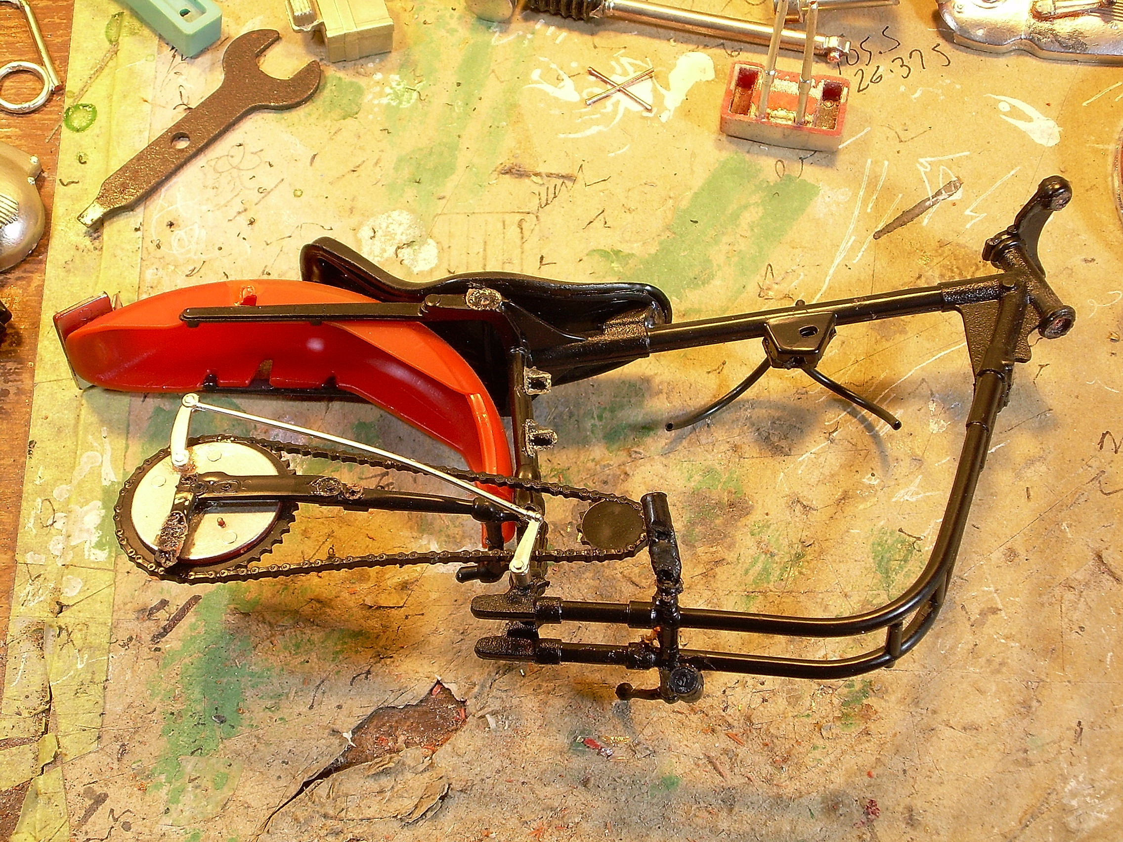
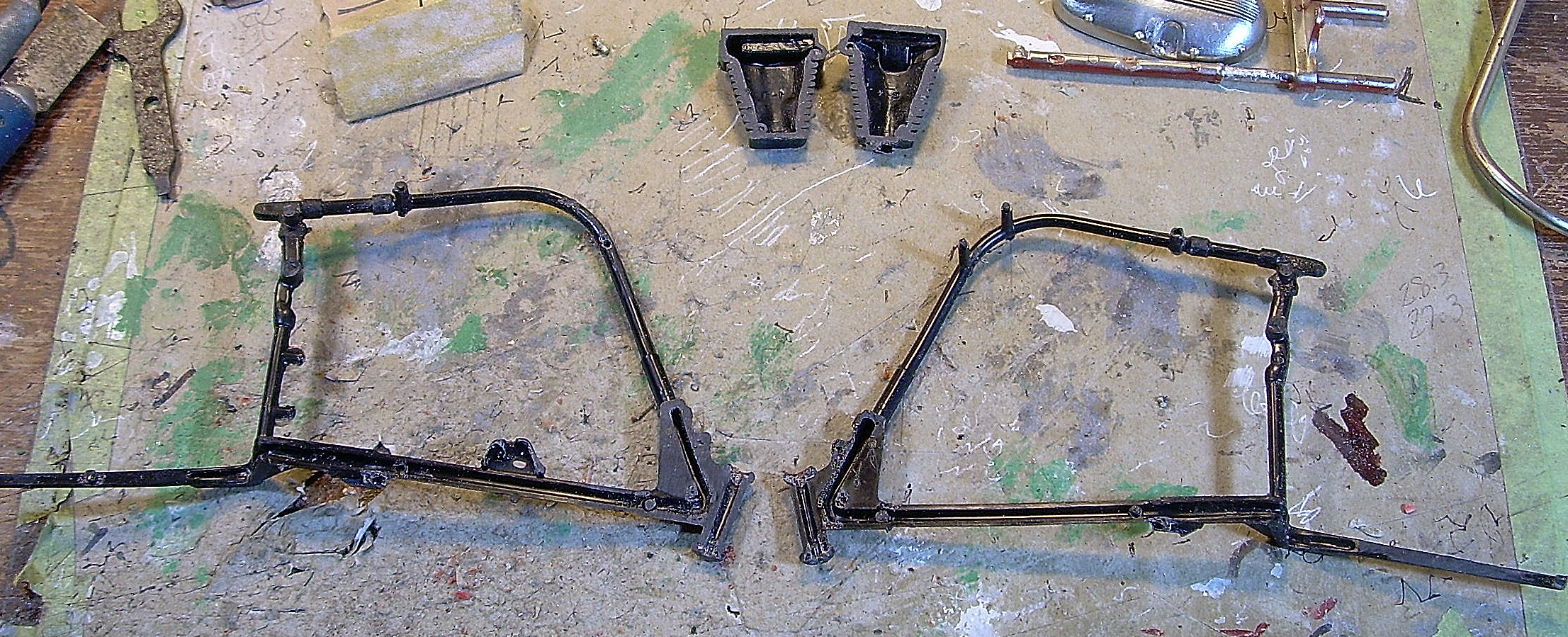
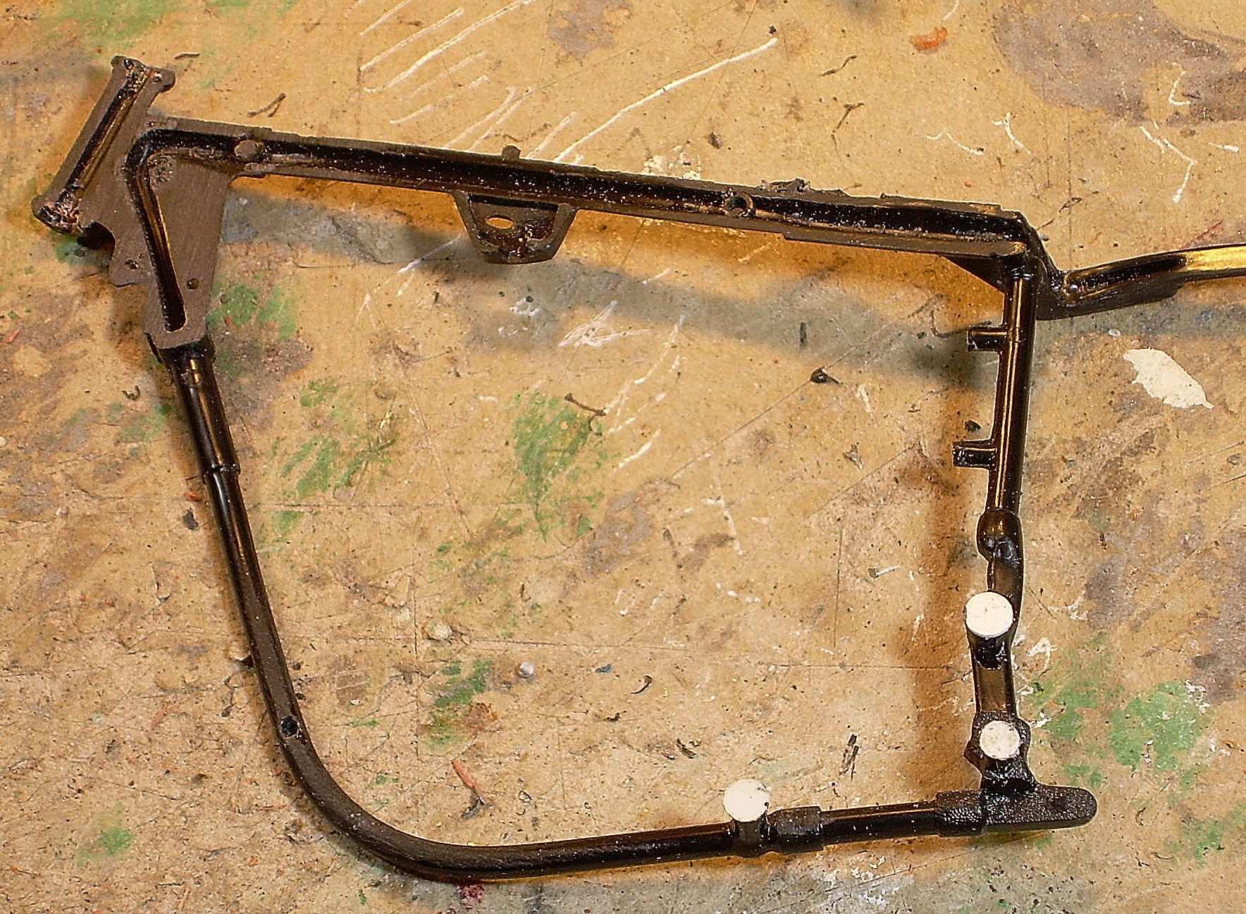
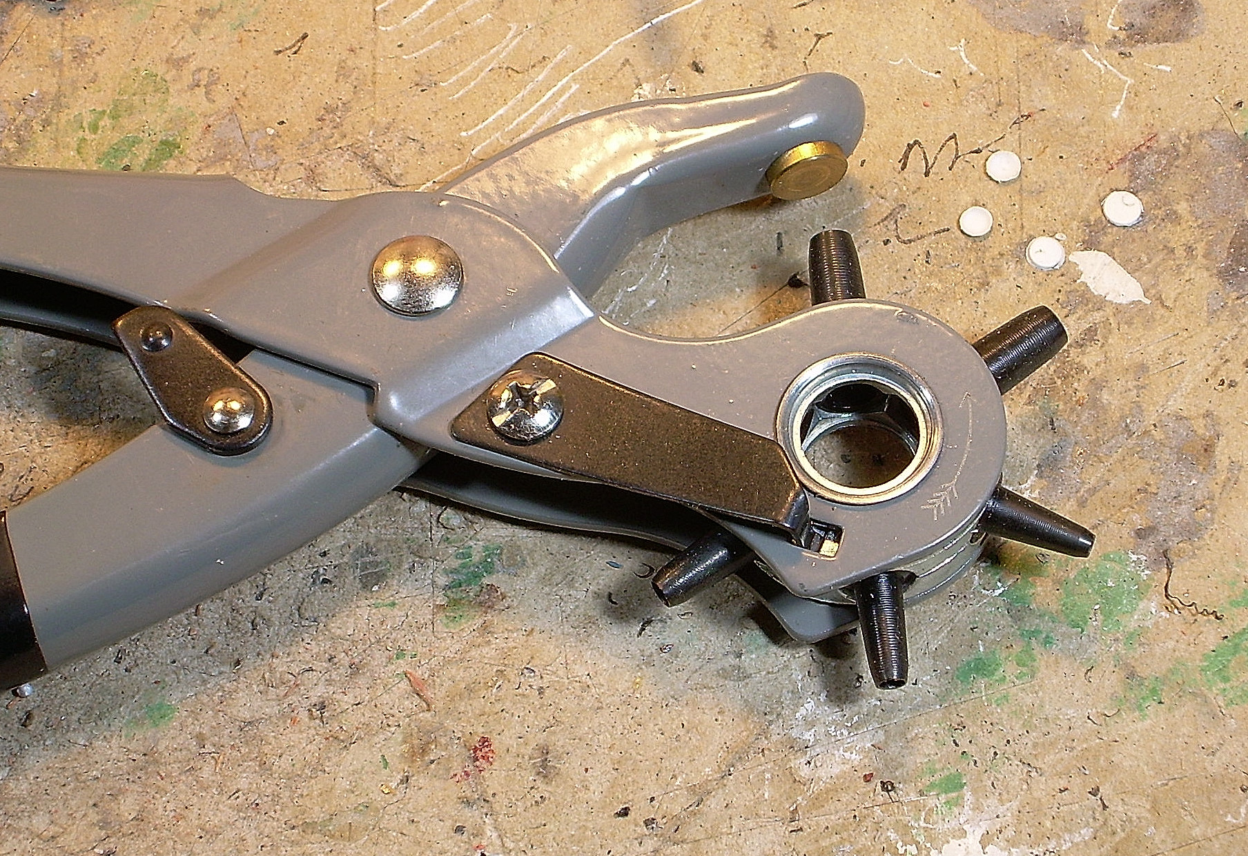
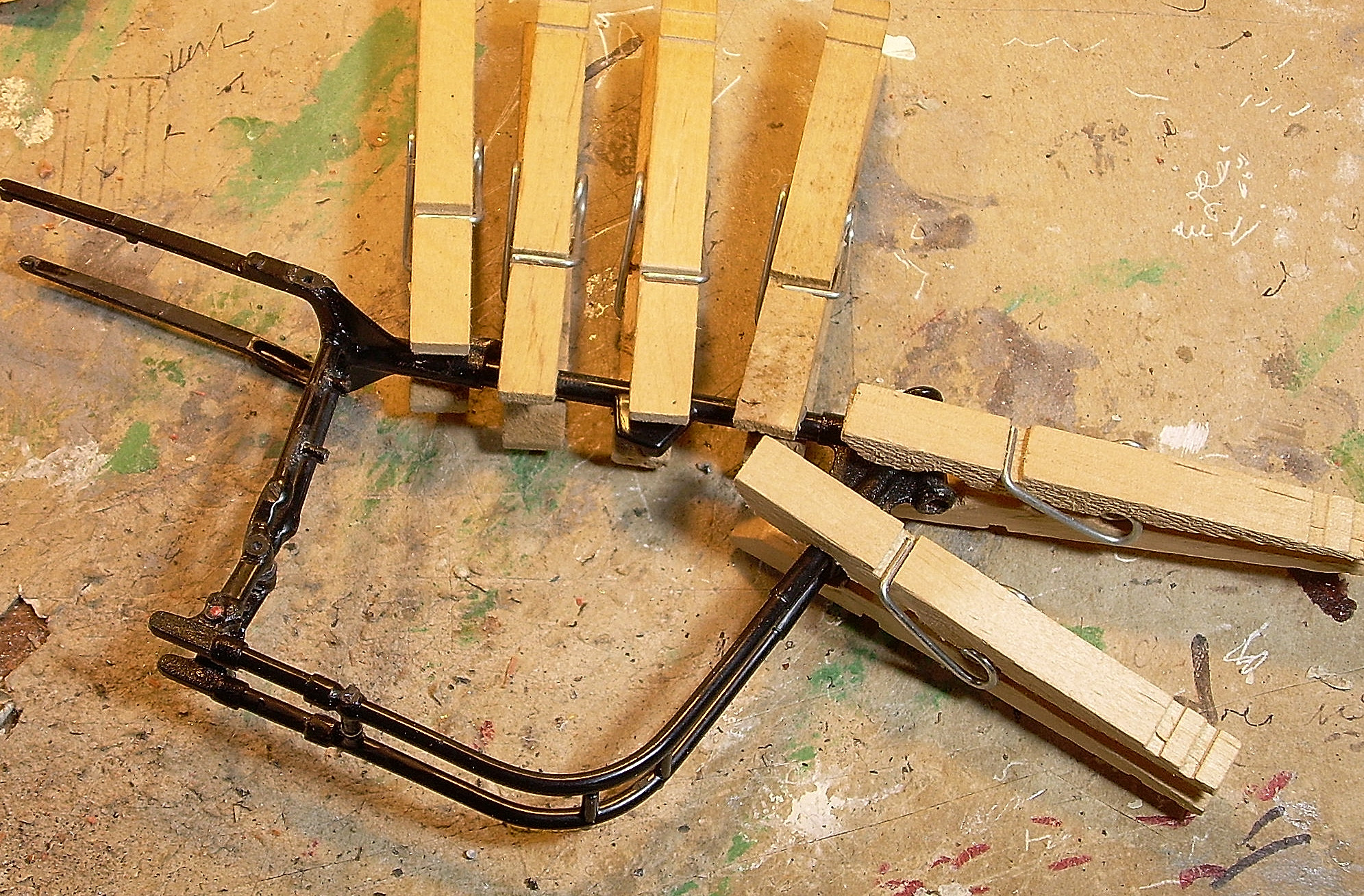
PART 3 Much of the frame was heavily glued together, again with the frame halves out of register, and several parts just stuck on where they didn't belong. The upper triple tree was also solidly glued to the frame, as was the shaft. After disassembly, the frame was carefully split, and the mating surfaces "machined" flat. The other cylinder has been done here too. When I split the frame halves, I had to saw through several heavily glued joints, and I lost about .010" of material due to the saw kerf. I replaced this prior to re-gluing, with dots of .010" styrene. A very handy tool to have for punching holes and making dots is made by Stanley. Frame halves back together, in correct alignment this time.

-
Revell chopper
Ace-Garageguy replied to zaina's topic in WIP: All The Rest: Motorcycles, Aviation, Military, Sci-Fi, Figures
Looks good. -
65 Chevy Shcool Bus
Ace-Garageguy replied to Oldmopars's topic in WIP: Model Trucks: Pickups, Vans, SUVs, Light Commercial
Thanks for your response. Much appreciated. -
My scanner is down, but in a couple of days I should be able to post a shot of the drawings in the mag, and as much of the text as is necessary. The author of the article, Alan Armitage, was a professional model builder employed by Revell at the time, and was an early promoter of using sheet and strip plastic for model RR applications...at a time when the "serious" folks in the hobby were resisting the influx of plastic products.
-
There was a highly accomplished aircraft modeler who had posted a wonderful video on YouTube on scribing panel lines, complete with instructions for grinding a special tip on a tool that would remove material without spreading or raising the adjacent plastic. Unfortunately, last time I tried to pull it up, it was gone. Just last night, I found directions for making a very similar tool in a 1959 copy of Model Railroader magazine.
-
65 Chevy Shcool Bus
Ace-Garageguy replied to Oldmopars's topic in WIP: Model Trucks: Pickups, Vans, SUVs, Light Commercial
Very interesting, nice start. All the "Bonnet Bus" kits I've seen are 1/32 (which yours appears to be), but your front sheetmetal appears to be from a 1/25 kit. Am I misunderstanding something? -
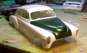
Heller 1949 Talbot Lago Grand prix racer
Ace-Garageguy replied to samdiego's topic in Car Kit News & Reviews
Good looking model. I finally got one of these a few months back, and it's quite a bit nicer than the old SMER / Merit kit of a closely related car. Here's more info on the Heller kit... -
Carburetor position?
Ace-Garageguy replied to 426 pack's topic in General Automotive Talk (Trucks and Cars)
This particular design of carb is usually oriented as in the lower photo. The floats and fuel level in the bowls can be oddly sensitive to G-forces from cornering or hard acceleration in each orientation. Tuning problems can be the result, but it really depends on the particular application. Also, depending on the intake manifold design, having both chokes (and all the primary throats) on one side could be another problem (though the chokes have been removed from the carbs in the upper photo). Carbs oriented as in the upper photo would also complicate linkage design to an extent. -
It's really more a Buick 340 V8 (which is a cast iron derivative of the aluminum 215) with two cylinders cut off, but that's still not the right way to think of it. The Buick aluminum 215 V8 was replaced with a cast iron engine built on the same architecture, and the 3200/3700/3800 family was developed from that. It was introduced in 1962 in a 3200cc displacement (198 cu.in.). The 3800 family, though a very popular engine, is unusual in that it has 90 degrees between cylinder banks, where most 6-cylinder V engines have 60 degrees between banks. It was done that way so that production machining of the blocks could be done on the same tooling as Buick's V8 engines. But the 90 degree configuration used in a V6 results in uneven firing impulses, which makes the engine seem rough-running. Jeep began using the engine in 1965 (Jeep eventually bought the tooling in 1967) with a very heavy flywheel to dampen out the odd-fire vibrations. That was addressed by GM in 1977 (GM bought the tooling back from Jeep in 1974) by replacing the crankshaft with one that incorporated "split" con-rod journals, resulting in an "even fire" engine.
-
Sorry to hear she got hurt so badly, glad she's got good care and a good home.
-
Real cars: set pinion angle/finding "true horizontal".
Ace-Garageguy replied to LDO's topic in The Off-Topic Lounge
Glad to help. I added a little more material to clarify a couple points, but I think I hit the necessary spots. -
Good rattlecan (or any) paint jobs depend on two major factors: 1) Meticulous surface preparation and primer work, and 2) Developing good, consistent spray technique. Enamels can be difficult to get repeatable results from when shot right out of the can, which is why a large number of modelers prefer either automotive lacquers intended for real cars (like Duplicolor) or hobby-specific lacquers such as Testors and Tamiya. This hood is Duplicolor rattlecan... This is Testors... Airbrushing is another ballgame entirely. Unfortunately, there are many really GOOD methods that are used to get excellent paint finishes, and they could fill a thick book. Here's one thread on this forum. There are many more. Read as much as you can, do some experimenting, and try to develop more specific questions.
-
Real cars: set pinion angle/finding "true horizontal".
Ace-Garageguy replied to LDO's topic in The Off-Topic Lounge
A car doesn't need to be sitting level to determine these angles, as it's the crankshaft centerline that everything else is based on. While setting this up, it IS good to start with the car at as close to the finished ride height and stance as is practical with the tools at hand...particularly if it's carbureted. We usually use dummy coil-overs or something similar to achieve this when building a car from the ground-up, or if it's some kind of heavy mod / engine swap, the car can be ballasted to operational weight on its actual suspension (and the actual wheels / tires that will be used). Measure the angle the chassis makes with the ground, and when you jack it up on a lift, or put it on stands to work on, maintain this angle. The tops of the valve covers are almost always dead parallel with the crank centerline, so they can be used for placing an angle finder to determine final configurations on engine and trans mounts to get the desired angle of the crank centerline (which will naturally be the same as the trans output shaft) relative to the ground. You'll note that carbureted V8 engines usually have an obvious angle milled into the top of the intake manifold that's not parallel with the tops of the valve covers. This is to allow the carb to sit relatively level most of the time (when the tail of the crank is lower than the front to achieve the proper angle) so the float can do its job correctly. Usually, when building a V8 powered car, using an old carb-style manifold with a level on the carb mounting flange will get you very close. NOTE: DISREGARD THE MEASUREMENTS BELOW. THE ILLUSTRATION IS ONLY TO DEMONSTRATE THE ANGLE MILLED INTO THE TOP OF THE MANIFOLD FOR THE CARB BASE. It's particularly important that the angles of the crank / trans output shaft and the driveshaft pinion shaft match when the vehicle is in its normal driving-down-the-road stance. Some suspension systems will allow the rear axle to rotate somewhat during acceleration / braking and bump / rebound (changing the pinion angle slightly) but you need to start as close as you can.