landman Posted March 28, 2018 Posted March 28, 2018 (edited) In the spirit of the 2018 challenge I decided to salvage an old racer and set it up with an inline 8.....from a 1930 Packard. We'll see what comes out. First step is to de-race the racer. Edited November 9, 2020 by landman
Vietnam Vet67 Posted March 28, 2018 Posted March 28, 2018 What did you soak your model in to get off paint and decals????????
DumpyDan Posted March 28, 2018 Posted March 28, 2018 Looks like Castrol Super Clean you can get it at Wally Mart works good and you can leave it and forget it. I once had a model in it for 6 months, no problem.
landman Posted March 28, 2018 Author Posted March 28, 2018 31 minutes ago, Vietnam Vet67 said: What did you soak your model in to get off paint and decals???????? Purple Power, a degreaser.
HDDan Posted March 28, 2018 Posted March 28, 2018 Hurray for the purple pond! This should be a fun build. Happy building.
bobthehobbyguy Posted March 29, 2018 Posted March 29, 2018 (edited) Neat idea. Definitely will be following along. Edited March 29, 2018 by bobthehobbyguy
landman Posted April 5, 2018 Author Posted April 5, 2018 (edited) Received the transaxle and the turbos. This translucent stuff is hard to photograph.Then I have to start designing. then I have to send the design down two and a bit left for approval. No sense having something that won't run. Edited November 9, 2020 by landman
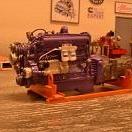
landman Posted April 7, 2018 Author Posted April 7, 2018 (edited) First order of business is to make the engine fit in a car which wasn't designed for it. To gain a bit of longitudinal clearance I removed a protuberance from the bulkhead and the fan bearing housing. It won't have an engine mounted fan anyway. Since we won't be going anywhere near LeMans speeds, I opened up the underpan (or is it undertray?) to provide clearance for the transaxle. With the transaxle located by a rod we can now refine the clearance requirements for the engine. Edited November 9, 2020 by landman
landman Posted April 9, 2018 Author Posted April 9, 2018 (edited) Opened up the bulkhead to clear the top front of the engine. will build up around it. Built up the Packard's exhaust manifold to accept the exhaust turbine flange width. Mocked up the turbos, sort of. Edited November 9, 2020 by landman
landman Posted April 15, 2018 Author Posted April 15, 2018 (edited) Decided to adapt this layout. The compressors feed into a single port on the intake manifold. The exhaust will come from two ports on the outside of the exhaust manifold. The pop-off tube will have to be redirected to the exhaust pipes. Is this one rad or two rads? Edited November 9, 2020 by landman
landman Posted April 15, 2018 Author Posted April 15, 2018 (edited) Fashioned some ports for the edge of the exhaust manifold. Modifying the stock car's fuel cell to fit. Edited November 9, 2020 by landman
landman Posted April 15, 2018 Author Posted April 15, 2018 (edited) A short investigation on the internet hints at there being only one rad, so two lines. Got the plumbing tools out. Edited November 9, 2020 by landman
landman Posted April 16, 2018 Author Posted April 16, 2018 (edited) More hacking and slashing at the bulkheads. Edited November 9, 2020 by landman
landman Posted April 17, 2018 Author Posted April 17, 2018 (edited) Still playing with clearances. Had to remove some ductwork off the top of the body. Reminds me of the hood on Eric McLeod's Duesenberg. Made some motor mounts Edited November 9, 2020 by landman
Rider Posted April 17, 2018 Posted April 17, 2018 (edited) Some real good imagineering going on here. Edited April 17, 2018 by Rider
mecklm Posted April 17, 2018 Posted April 17, 2018 The inlets to the turbos are currently connected to each other with that short piece of tubing. I'm interested in seeing how you route the inlet air to that tube. Are you going to try to match up an inlet tube with the existing duct on the top/front of the rear cover? That will be a cool setup when you're finished! Mike
Recommended Posts
Create an account or sign in to comment
You need to be a member in order to leave a comment
Create an account
Sign up for a new account in our community. It's easy!
Register a new accountSign in
Already have an account? Sign in here.
Sign In Now