Russell C
-
Posts
1,930 -
Joined
-
Last visited
Content Type
Profiles
Forums
Events
Gallery
Everything posted by Russell C
-
 Huh. The JDM version of the Plymouth Arrow. Didn't know anybody made a kit of that.
 -
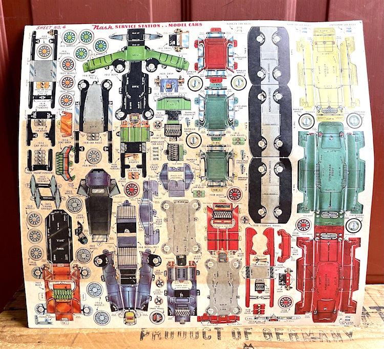
Tempted to drop parts of the page below into my Corel drawing program so I can print out the red Ambassador, and then see if it is beyond my skill level these days to assemble it. I can vouch firsthand that paper models aren't always child's play to put together. The Bluesmobile I did many years back really was a fiddley kit - borrowing KCSlammer's Fotki photo of it here. (had to also build my own award trophy for it out of a McDonalds burger box, which was actually easier to do!)

-
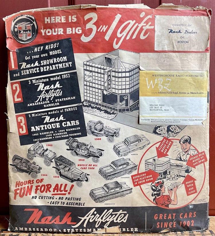
Not something you run across everyday in the eBay Vintage Model Cars section: https://www.ebay.com/itm/266717238942 . Would be entertaining to get nice flat scans of the original to do paper printout reproductions to put together. Since eBay auction links are short-lived, here's a permanently saved Archive link to at least have a minimal look at what the seller had: https://web.archive.org/web/20240313192938/https://www.ebay.com/itm/266717238942
-
1:1 kitbash?
Russell C replied to Earl Marischal's topic in General Automotive Talk (Trucks and Cars)
Junkyard boss to employee: "See all that piled up in the corner over there? Do something with it." Days later, employee: "How's dis?" Boss: "I meant, get rid of it all!" -
A study in structural bondo...
Russell C replied to Ace-Garageguy's topic in General Automotive Talk (Trucks and Cars)
I could only watch 13 of the first 23 minutes. Poor Cougar. I can just imagine an owner of such a thing allowing a son to take it out for a drive, who calls in 10 minutes later to say "Dad, I did a Dukes of Hazard style jump over the railroad tracks - just a little jump! - and, well .... the car broke into maybe 16 or more pieces ........" -
On a few occasions for my GSL Contest entries, I printed out the backstory, where it was a great excuse to pass off some of my shortcomings on the build as actually being exact replication of the shortcomings of the 1:1 vehicle I was "replicating." Here's the printout from the Under Glass thread for my backwards VW bug (I really should have budgeted more time to do a better paint job).
-
What would YOU like to see as a model
Russell C replied to JeroenM3's topic in General Automotive Talk (Trucks and Cars)
'76 Chalet #0589 in the top pic, '77 #1460 in the bottom pic. Mentioned this somewhere else here at MCM, but for new folks, I'll repeat some of it: I used to own #1747 'til I needed the money more than a big no-ideal-available-place-to-fix-it-up rig. I am the current caretaker of the very old blazerchalet website (paying the bills to keep it online) and I have my hobby fun trying to keep track of every one of these ever made, supposedly only 1,780 (figure comes only from this 1979 article's 2nd paragraph - GM lost the figures for the GMC Casa Grande version, but has said they made 1,555 of the Chevy versions). Another 'custom' that just came up for sale yesterday with 80+ reference photos is Chalet #0258 in Texas. Myself, I thought the only class win I perhaps could achieve at the GSL contest would be in Factory Stock for one of these, but I never got past figuring out whether the Monogram Blazer / Jimmy was more of an accurate basis then the MPC Blazer or the Revell one. Snagged all three as cheap eBay buildups about a decade back, and that's all the farther I ever got … -
Don't know how I missed that one top kit back in the day. Must-haves for every offroader; an axe, a shovel .... and a cannon.
- 39,060 replies
-
- 1
-

-
- johan
- glue bombs
- (and 1 more)
-
Autoquiz #597 - Finished
Russell C replied to carsntrucks4you's topic in Real or Model? / Auto ID Quiz
No clue. But I could say that if the thing was sectioned with a bit of a top chop and lowered somewhat, with more beefy rear wheels, it might look something like this.
-
Here's a 2-day old link update which can be read without logging into FB, you just have to click the gray X circle to get rid of the login box ..
-
STEVE SCOTT ,A.KA . [ UNCERTAIN T ]
Russell C replied to bpletcher55's topic in General Automotive Talk (Trucks and Cars)
If I was a better illustrator (I am not), the story I'd concoct is that Steve actually only turned an old cement mixer into just a cab-only rod, and shortened the donor victim's wheelbase.
-
I fully empathize. Without naming names, a particular someone I knew was essentially ordered by the doctor to take blood pressure-reducing pills and was advised to learn to relax. Said person did not, and late on, while on a rant about an item where the rest of us would say, "Really?? Are you kidding me?", said person then proceeded to have a fatal hemorrhagic stroke … and that was the end of that.
-
Let's See Some Glue Bombs!
Russell C replied to Snake45's topic in General Automotive Talk (Trucks and Cars)
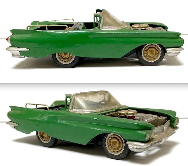
As if I needed yet another project … but I have a soft heart for unloved glue bombs which might end up tossed into the trash by estate salers rather than being relisted on eBay at slightly lower prices. So, I was the one-bid winner for this $20 one, which arrived in today's mail. Similar to my '62 Ranchero speedster rebuild, I can see where the original builder was going on this one, but what it needs is the rear wheels to be moved back to a more aesthetic position, and a hood with holes for the air cleaners (they are a tic taller than where the hood surface would be), and much neater build execution. While waiting for it to arrive in the mail, I altered the seller's eBay photo to see how it might look better with a hood, chrome instead of gold caps, and a bit more subtle teal tone color. Might actually need custom wheels, considering the hood cutout = more of a hotrod or sporty car. I can hide the back wheel arches with the fender skirts that came with my years-back '58 Pontiac glue bomb eBay parts car purchase, and the better-than-average '60 Buick I got in 2022 just for its front clip might contribute some items, too, such as the back bumper.
-
What does "NNL" stand for?
Russell C replied to spudmuffin1959's topic in General Automotive Talk (Trucks and Cars)
For a short bit there, I thought I might have learned something about an uncommon abbreviation for "national." But in this Acronym Finder, that word is not among them. "Never Never Land" is, though. When it comes to the real abbreviations for "national," this page says Nat’l. Natl. Ntl. Nat. NTL Meanwhile, I forget which airportit was where I had hours of layover time to kill, but I do remember how that was a good time for watching all of Doug Whyte's Model Car Muse video on the formation of the NNL, quite funny. -
That's unfortunate. I don't log into my Facebook page much, but it appeared the last couple of times I looked in, that he was flying right along with his build of a Titanic model. Many hopes for the best possible recovery!
-
Hello from county durham
Russell C replied to southern_northerner's topic in Welcome! Introduce Yourself
Welcome! As a Yank growing up in the vast open American West with not refined enough knowledge of the UK, I had to look that up. Seems that a common structure style in the smaller towns is a form of really long tan stone two-story residential buildings.
-
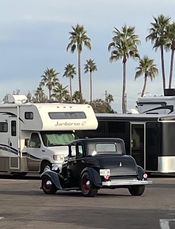
What did you see on the road today?
Russell C replied to Harry P.'s topic in General Automotive Talk (Trucks and Cars)
This afternoon in the land where snow and subzero temps are not a huge concern ...
-
Seems auction sellers are uploading more and more photos of their cars to the Bring a Trailer site: https://bringatrailer.com/search/?s=1959+Pontiac
-
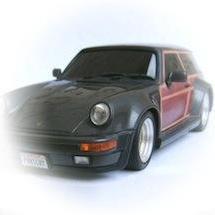
Koenig-Specials Porsche 930 "Road Runner" (Fujimi, 1/24 scale)
Russell C replied to Tommy124's topic in Model Cars
Nice! (bought that kit for the wheels alone that are on my avatar 911 wagon) -
What happened to the older builders
Russell C replied to Hamata1972's topic in Welcome! Introduce Yourself
Mike Siegman was at the last GSL contest in SLC, he actually helped me figure out the light rail ride from the airport to the hotel. -
Did not know that, I have no math sense, so my guess that that the two scales were always out of alignment. Worst I've ever experienced is 8°F, where my oil probably wasn't exactly equipped to be that cold, so it sounded like my engine was grinding up ice cubes when I first started it up.
-
What would a car modelers Hades be like:
Russell C replied to GLMFAA1's topic in The Off-Topic Lounge
Molded in a form of red plastic that bleeds through even the toughest type of paint primer. -
Autoquiz #596 - Finished
Russell C replied to carsntrucks4you's topic in Real or Model? / Auto ID Quiz
Finally one I know in an instant, except for the precise year. -
It's been done, actually, but in small scale diecast: http://dev.toywonders.com/ProductCart/pc/Greenlight-Gulf-Oil-Kenworth-T2000-Transporter-2017-1-64-scale-diecast-model-car-Light-Blue-Orange-29929-p21102.htm
-
Looking for ideas on how to widen rubber tires
Russell C replied to midlineqb's topic in Model Building Questions and Answers
Brian Croft here beat me to the punch way better than I could have done with the link to the Feb 2018 thread which I must have missed. Great suggestions within it! My late father gave me a mini-lathe with a variable speed drive, so that's what I'll use to spin tires, vinyl or some 2 piece plastic slicks that I got from MCM's Dan Doane where I can turn straight grooves into the plastic ones. The home-made cradle for a cordless drill sure looks handy for slowly spinning large model car pieces.