Chariots of Fire
-
Posts
2,802 -
Joined
-
Last visited
Content Type
Profiles
Forums
Events
Gallery
Everything posted by Chariots of Fire
-
Hey, Peter. I bought some of the FF chrome and it is really nice. The great part about it is that it can be brushed on so that it floods the area whereas Molotow and other pens are very restricted in the surface area they can cover. It appears to be very durable. Bright is ok with me. Certain details just cry out for a nice shiny surface. See you at CP!
-
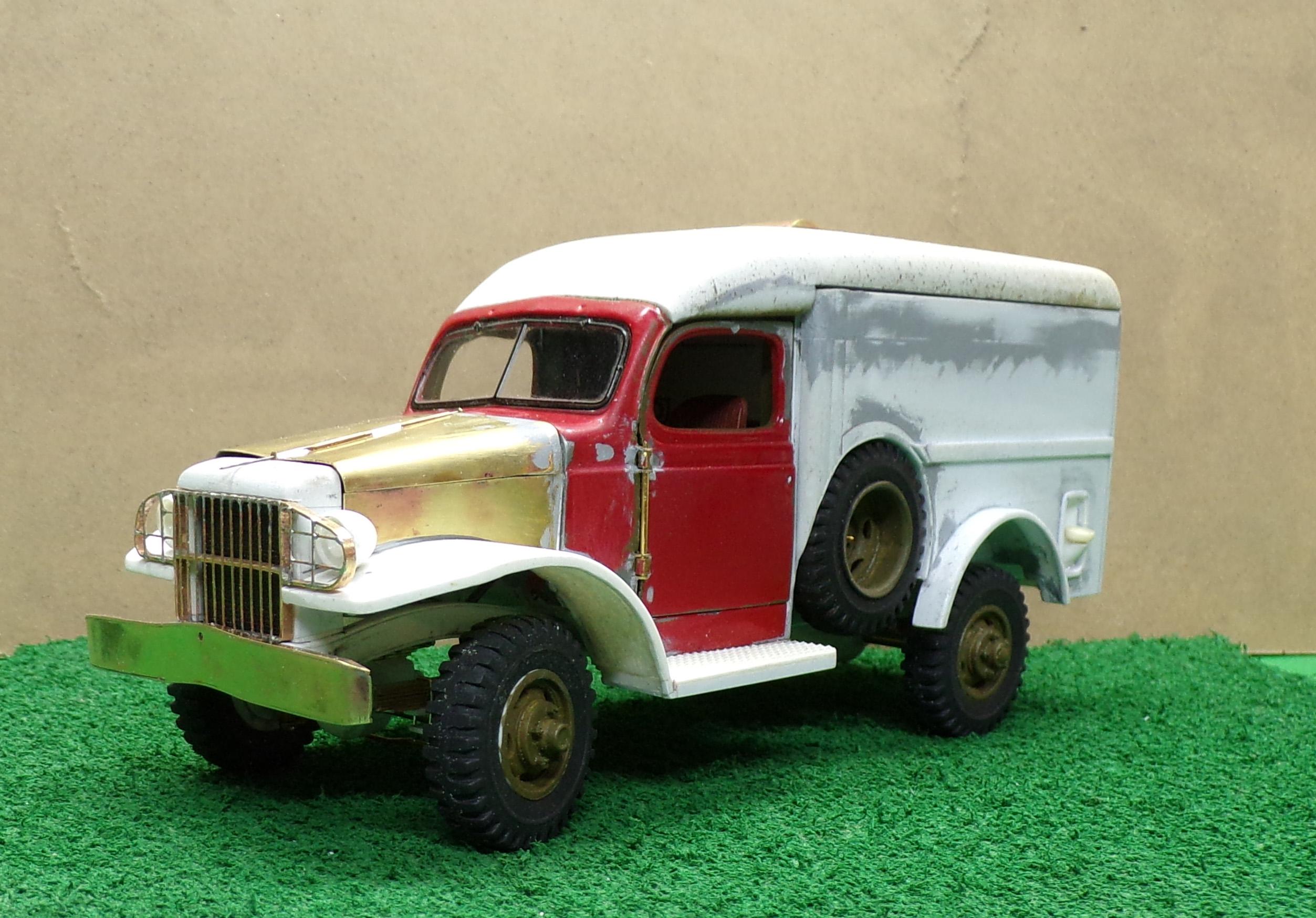
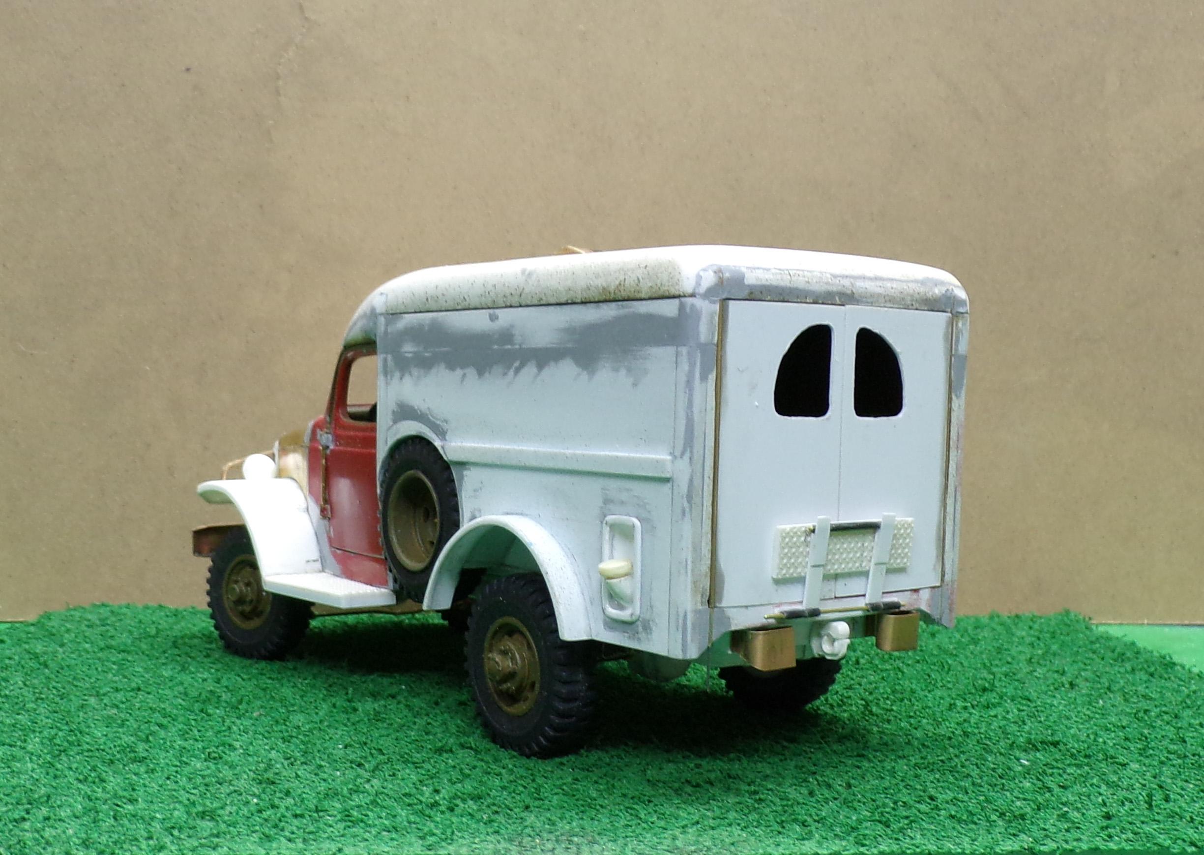
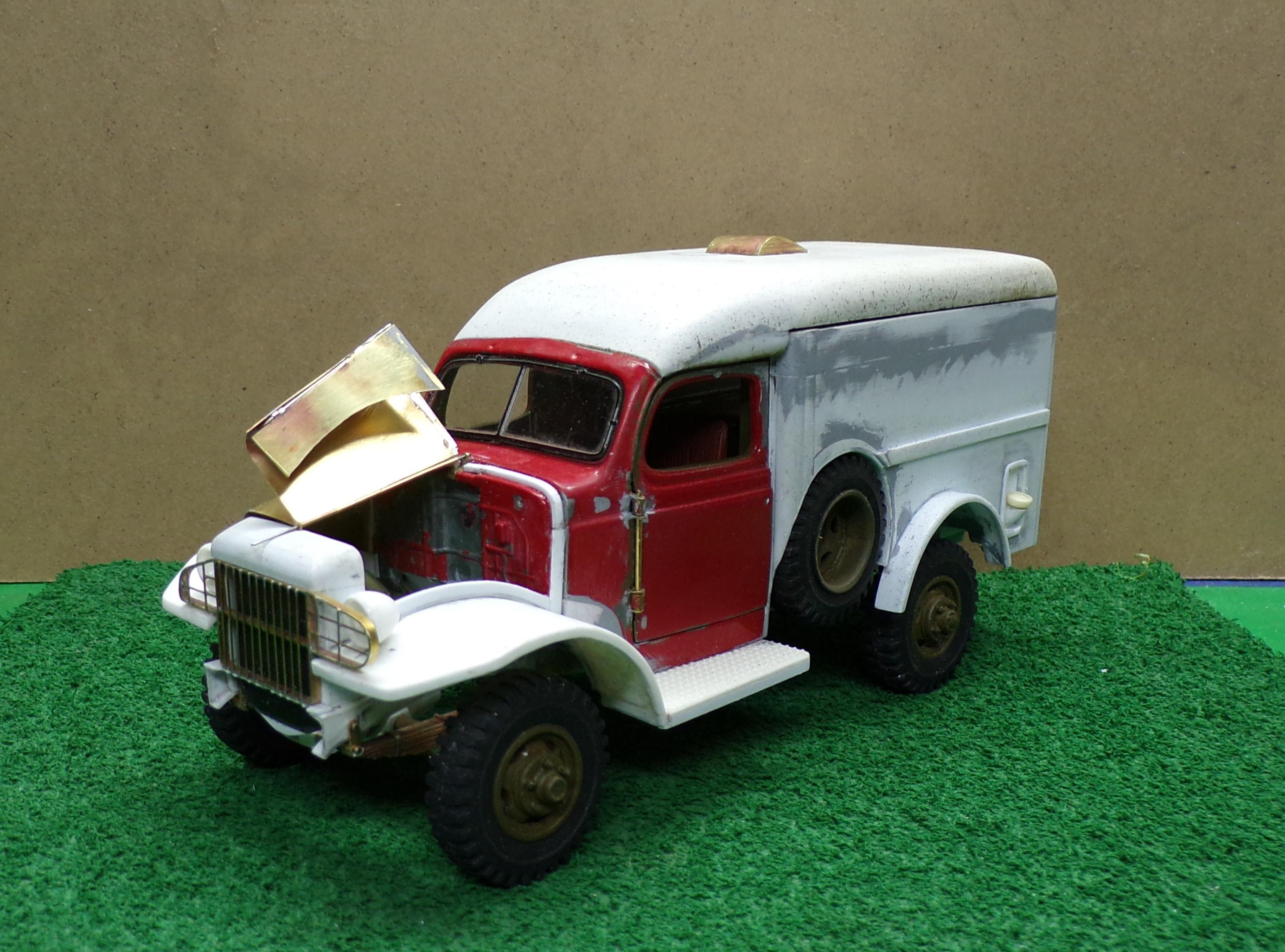
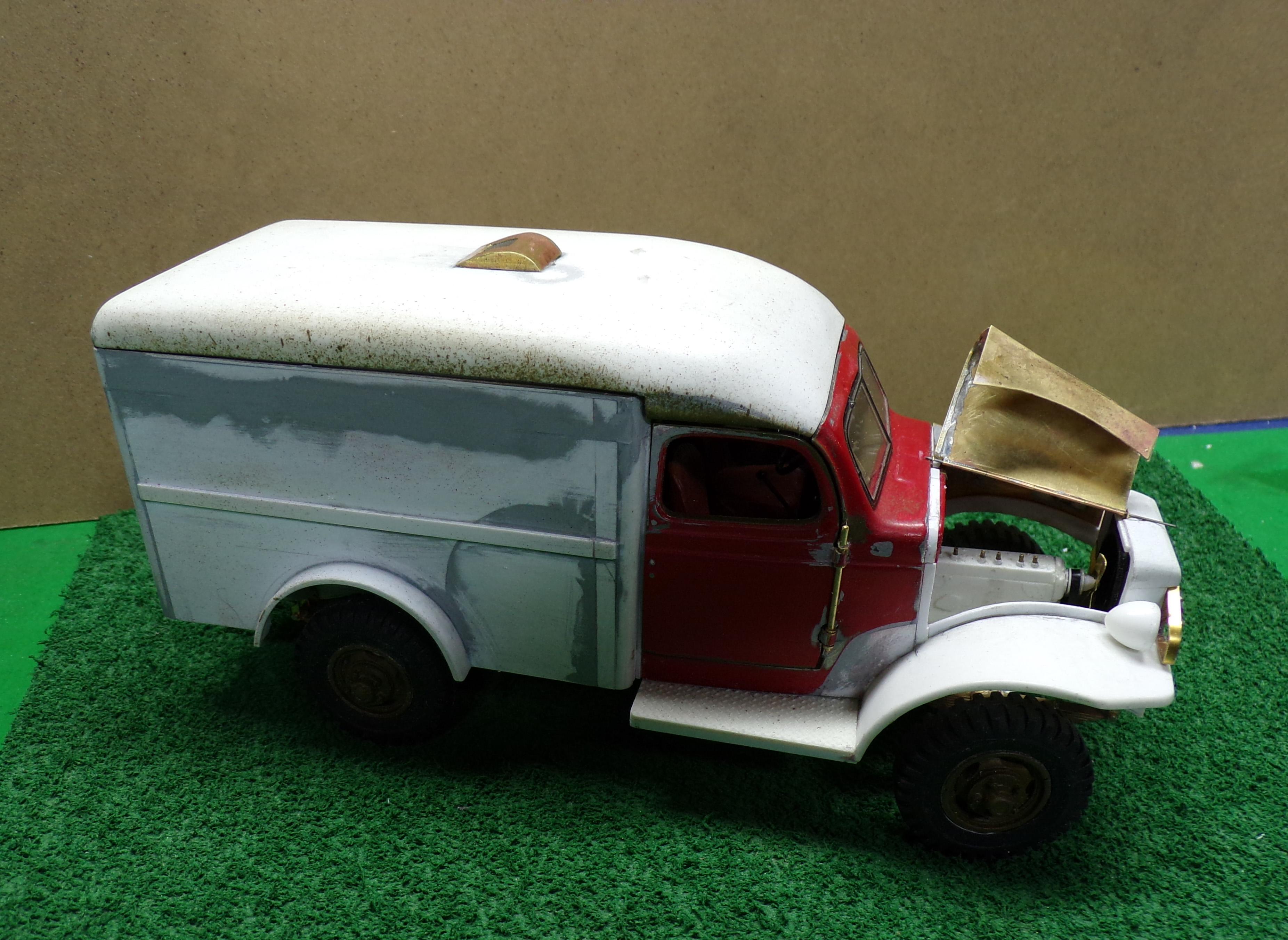
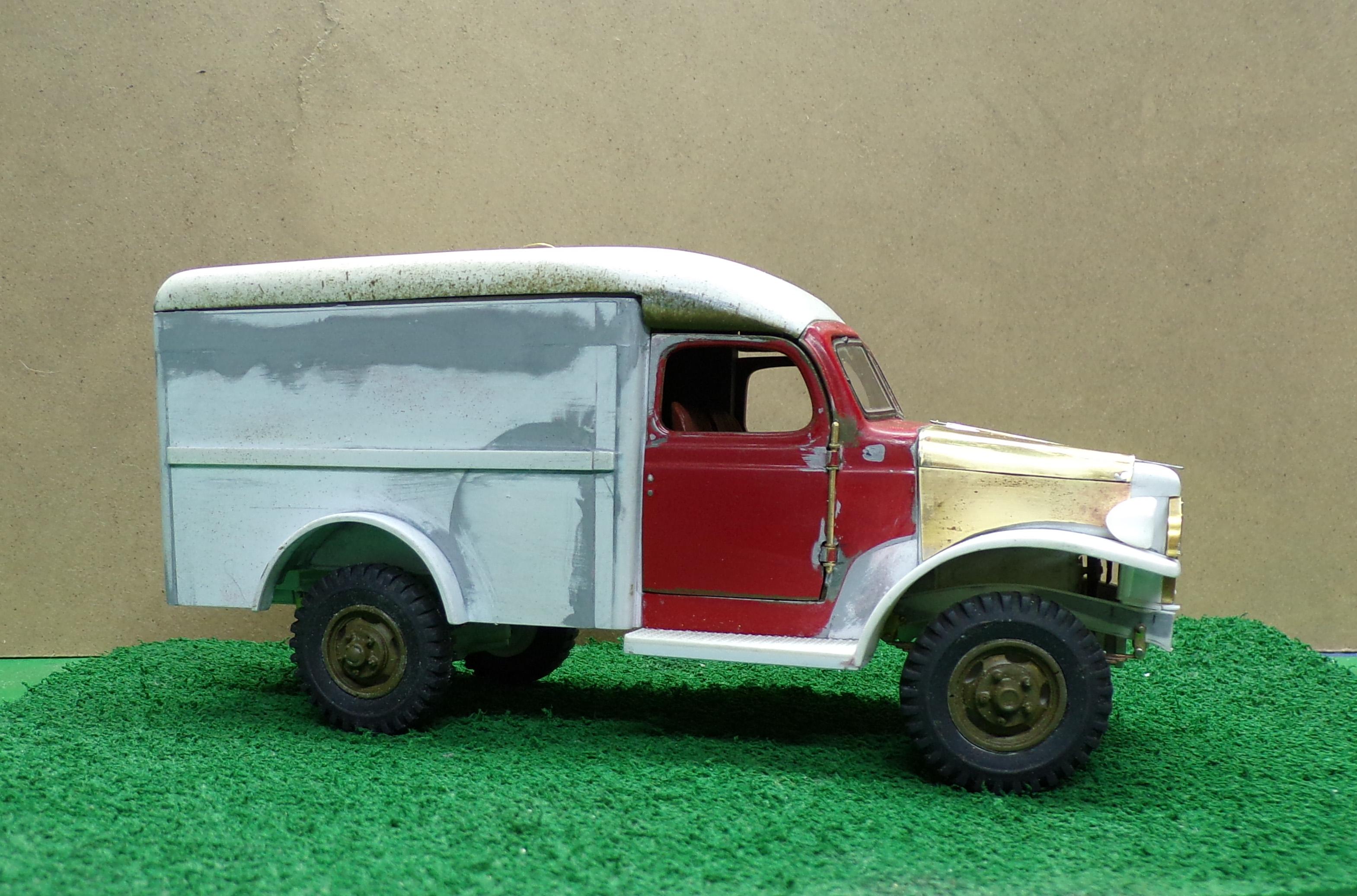
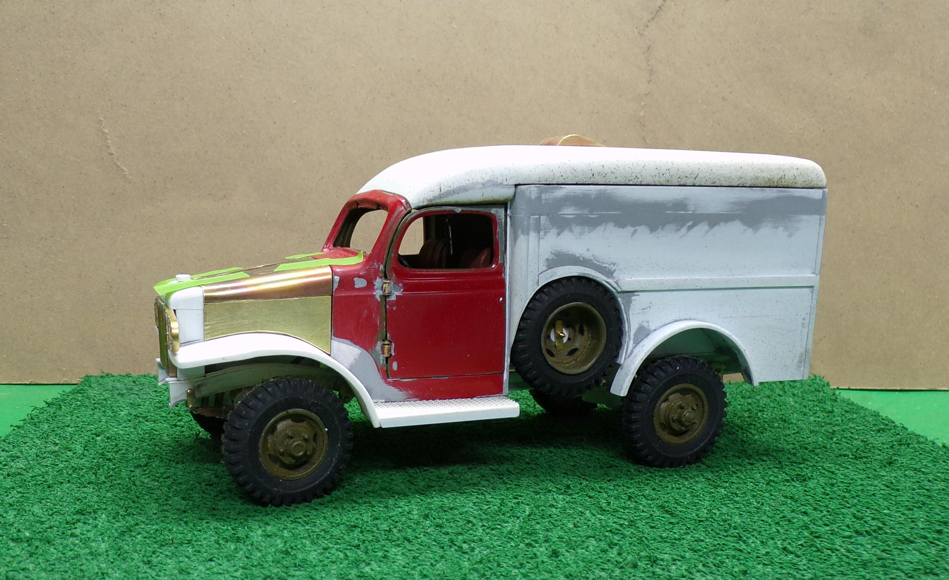
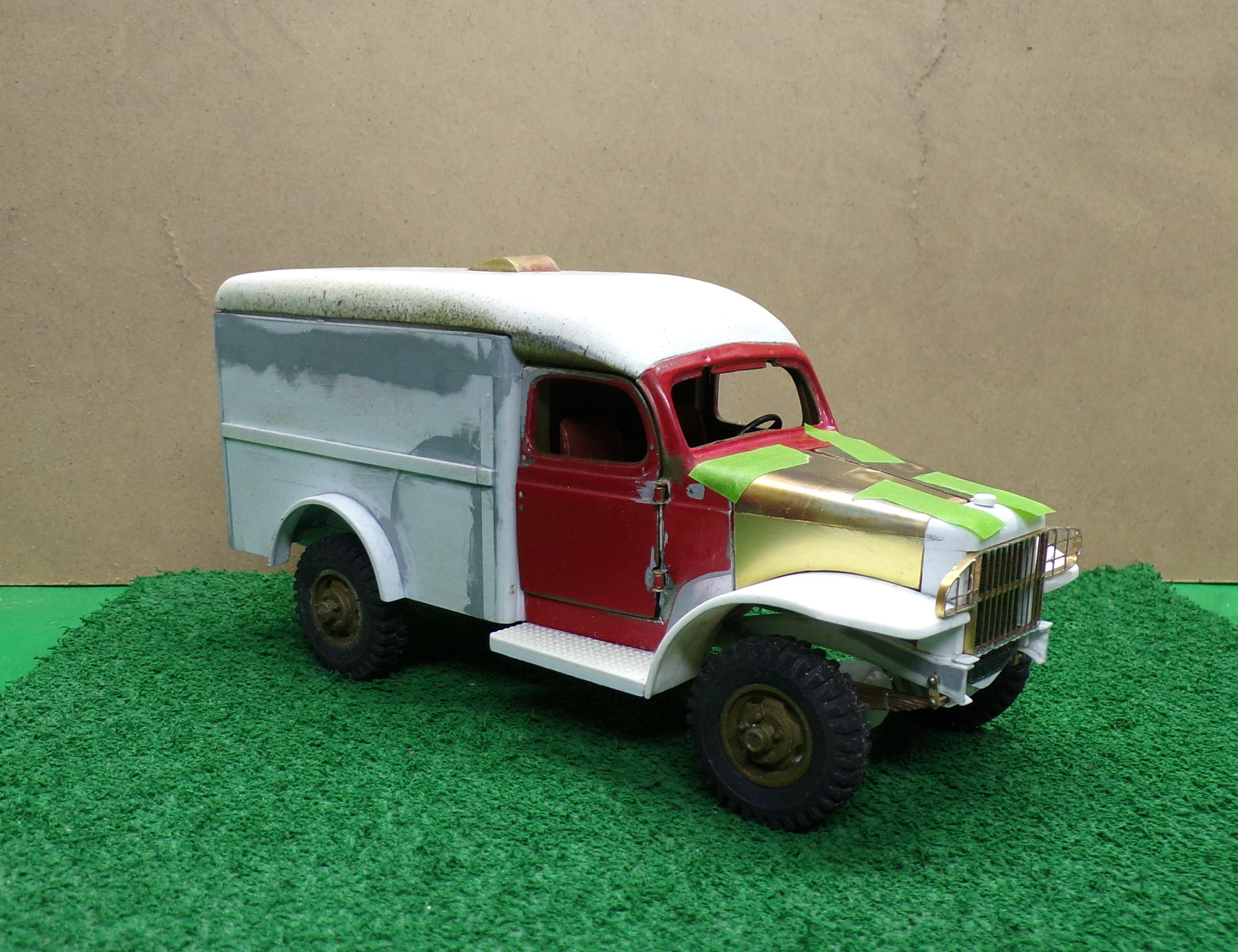
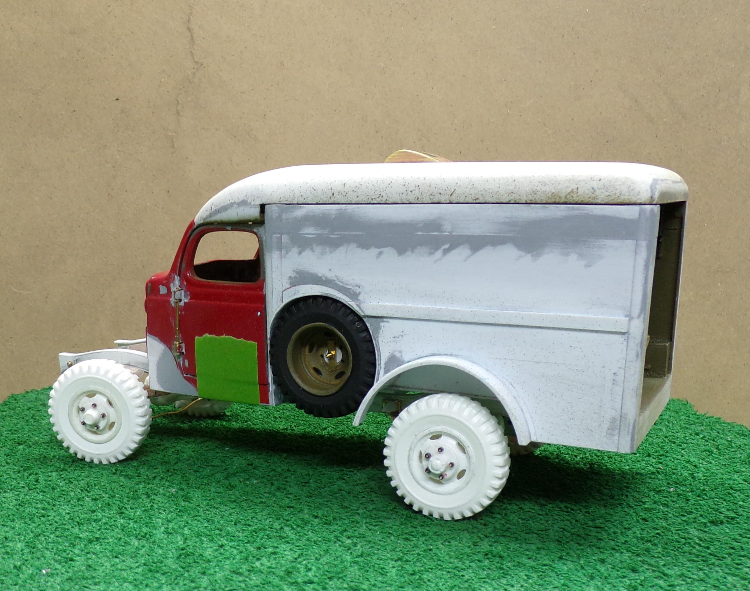
 Got a bit more done on the build. Rear doors are done and top has been secured to the body. The bumper is made of brass and has been mounted to the frame. Got some tow hooks to add.
-
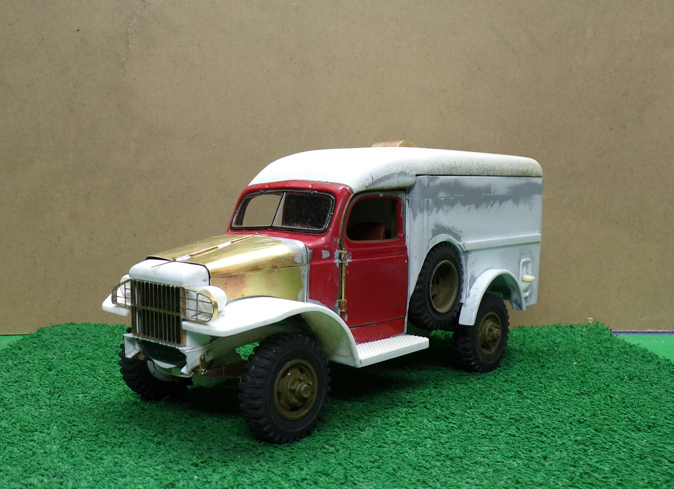
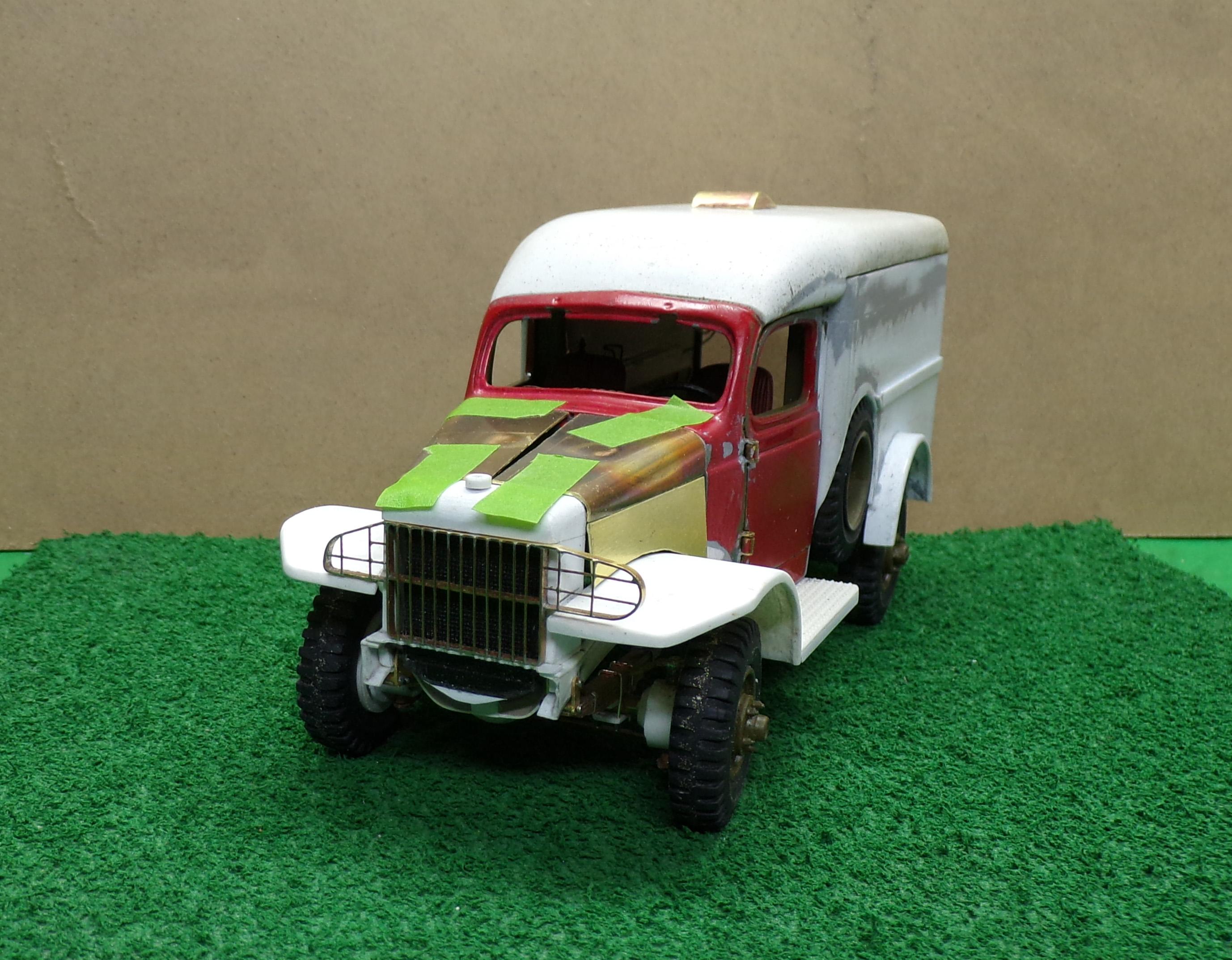
Got the hood done after a lot of trial and error. Headlights are in place temporarily and the fuel filler has been added to the left rear. The hood will sit flat when I get some pins mounted to hold it down. Two different curves make it hard to bend in two directions at once. But it's coming.
-
Yup! Getting there!
-
Got a lot accomplished in the last couple of days. The radiator is set along with the shroud and the fenders and running boards are in place. Today I worked on the hood sections. Still some tweaking to do on the center of each piece to get it ready for a hinge.
-
Just comparing the model to the real truck it looks like the grill could be raised just a tad. Match the height to the hood by adjusting the edges of the hood so it is squared off to meet the grill. Then reshape the top of the fenders accordingly. I think you also have to take out the sculpture line that goes around the fender opening. So don't put it away yet! It's getting there.
-
Looking good, Mark. More and more like an IH every day! Keep it going. Hope you are feeling better.👍
-
It's a reverse clamp sort of thing, spring loaded so it grips. Has two triangular pieces of metal that draw off the heat.
-
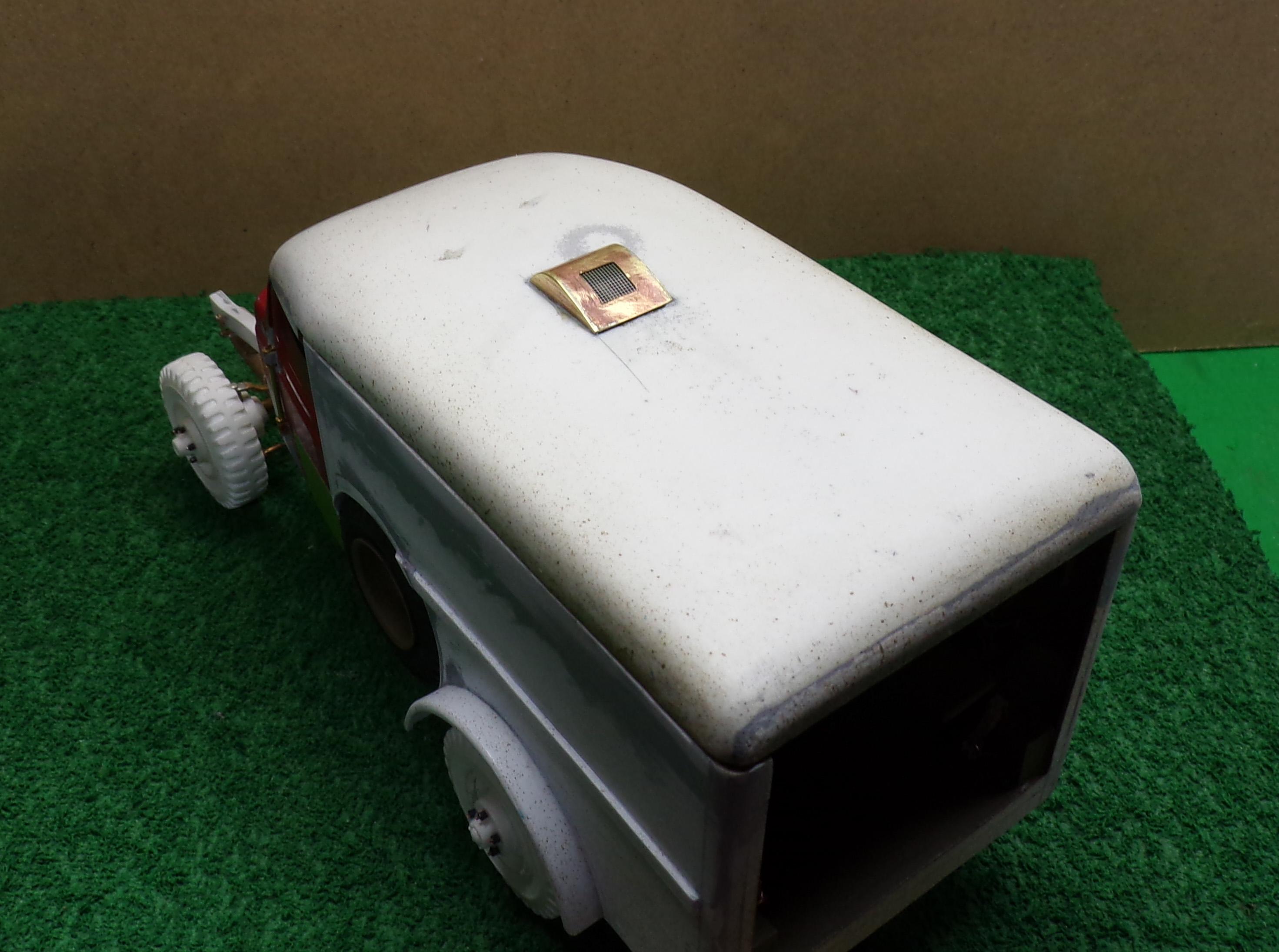
I don't do videos but at least I can explain what I do. The brass is thin sheet of 0.015" thickness. It has to be clean so I do so with some steel wool. For the air vent, the top curved surface was made first by cutting out a piece of the approximate length and width I need and was then trimmed to final size. I bent it slightly using a piece of brass tubing as a guide to get the curvature even. Then I laid the curved piece on its side on top of another piece of brass sheet. Liquid flux was put along the edge of the curved piece along with some small pieces of thin silver bearing solder wire. I use a small butane torch to heat the brass sheet, holding the torch away from the sheet 4-5 inches. The heat is applied in the area that you want the solder to flow, in this case against the curved edge of the other brass sheet. Once it flows take the heat away and let it cool. Then the second side was applied the same way. Final trimming of the sides was done after the solder cooled. It only takes a few seconds. After that the hole was cut for the photoetch mesh using a drill for a starting hole and then small files. Whenever I can I try and solder pieces that are oversized and then trim them down afterwards. Trying to solder finished pieces without getting them misaligned is nearly impossible. I also have a soldering iron that has adjustable heat. I use that for small pieces where only the minimum heat is applied. I also use a heat sink to draw heat away from places I don't want it to go. Sometimes resistance soldering equipment is better to use but the equipment I have has heavy cords and I have found it hard to keep things in place during the soldering process. The benefit of such equipment is that the heat is directed right at the point where you want the solder to go. Eliminates a lot of cleanup. Hope this helps, Mark. My suggestion is give it a try and see how it works out.
-
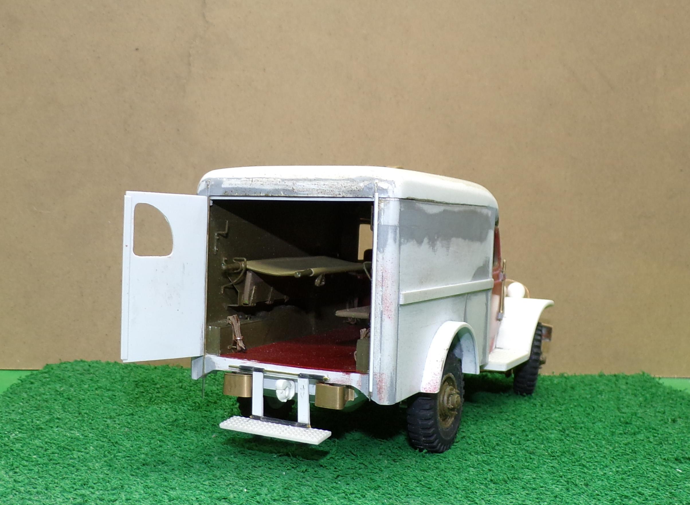
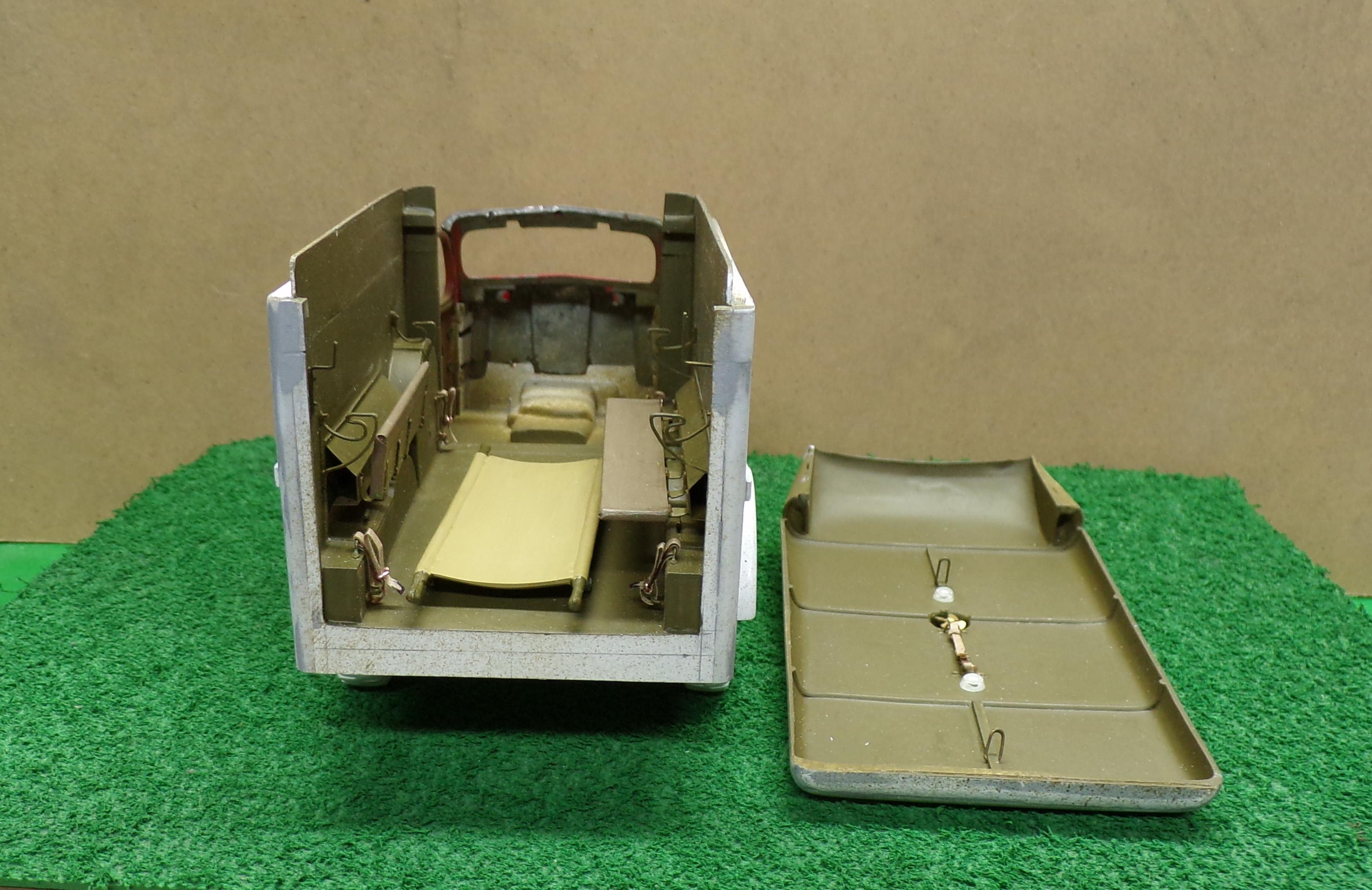
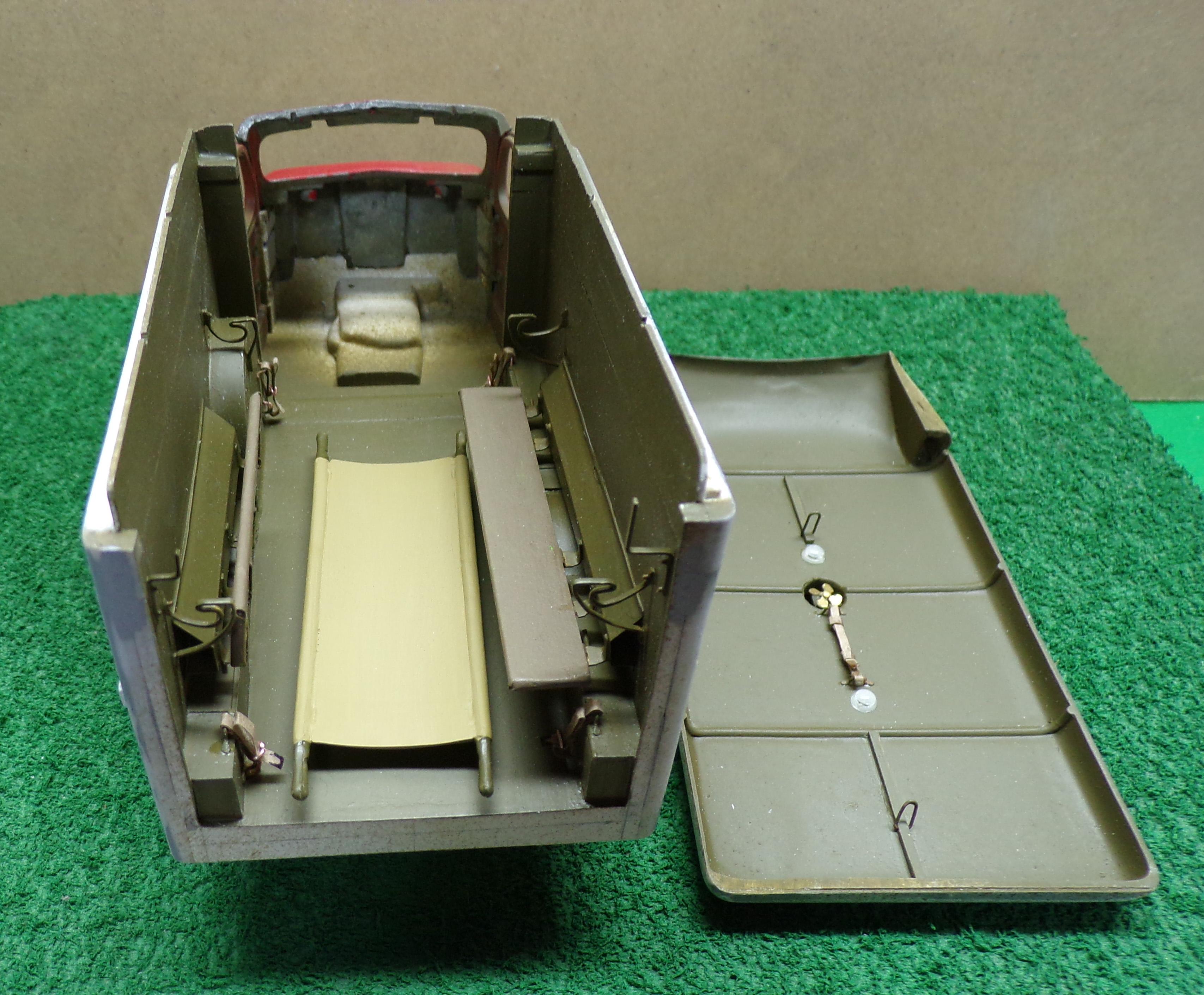
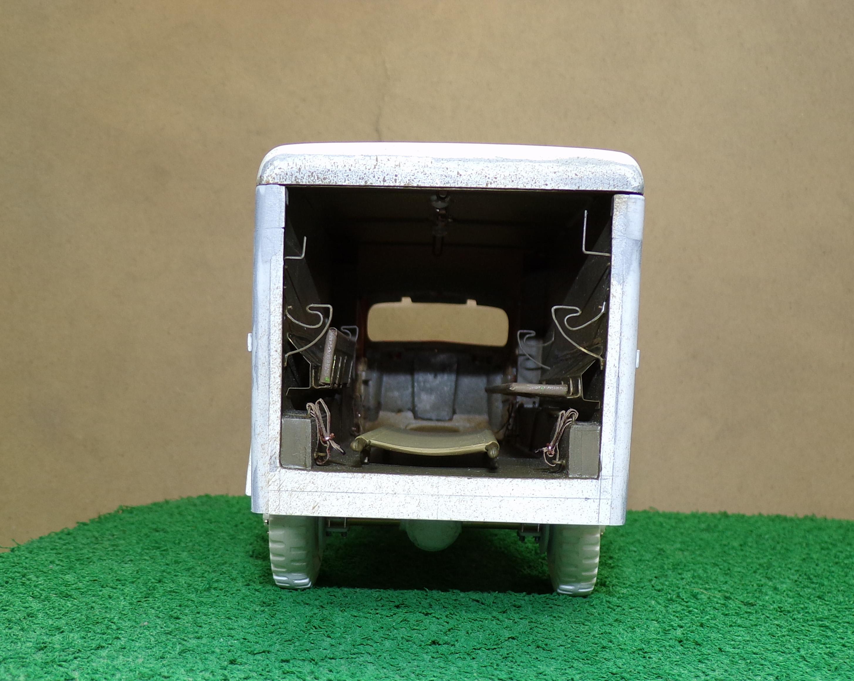
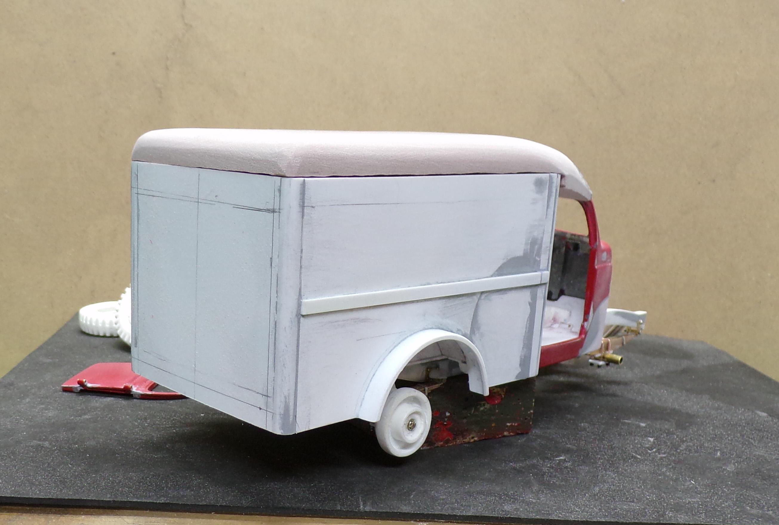
Made some real progress in the last few weeks. It took a while but the effort was worth it. The top needed some adjustment and the body sides also needed modification for height and length. With that accomplished work on the body interior commenced. There just was no way to get the details inside with the top glued down but with them now complete I can do that. The dark red linoleum floor has since been added but is not shown in the photos below. Stretcher brackets, compartments for emergency supplies, arm and leg splints, interior lighting and support brackets were all done for the body and top. The seats are folding type. The one on the left is up since a stretcher will be supported on that side. The one on the right will stay down. The straps near the floor are for securing loose materials. The two loops inside the top are the other stretcher support brackets. Rope ties from the stretcher will be hung from them. The top is now ready for final installation. The cab doors have been hung and fitted. The last remaining bit of body work to be done once the top is secure includes feathering in the top with the windshield and filling in the two areas where the curved wrap is above the doors. The drip edge will be installed along the joint between the top and body sides. One last detail is the air vent in the top. It is made of 3 pieces of soldered brass with a photoetch mesh inside. There is a fan also inside the opening that can be seen from the top and from inside.
-
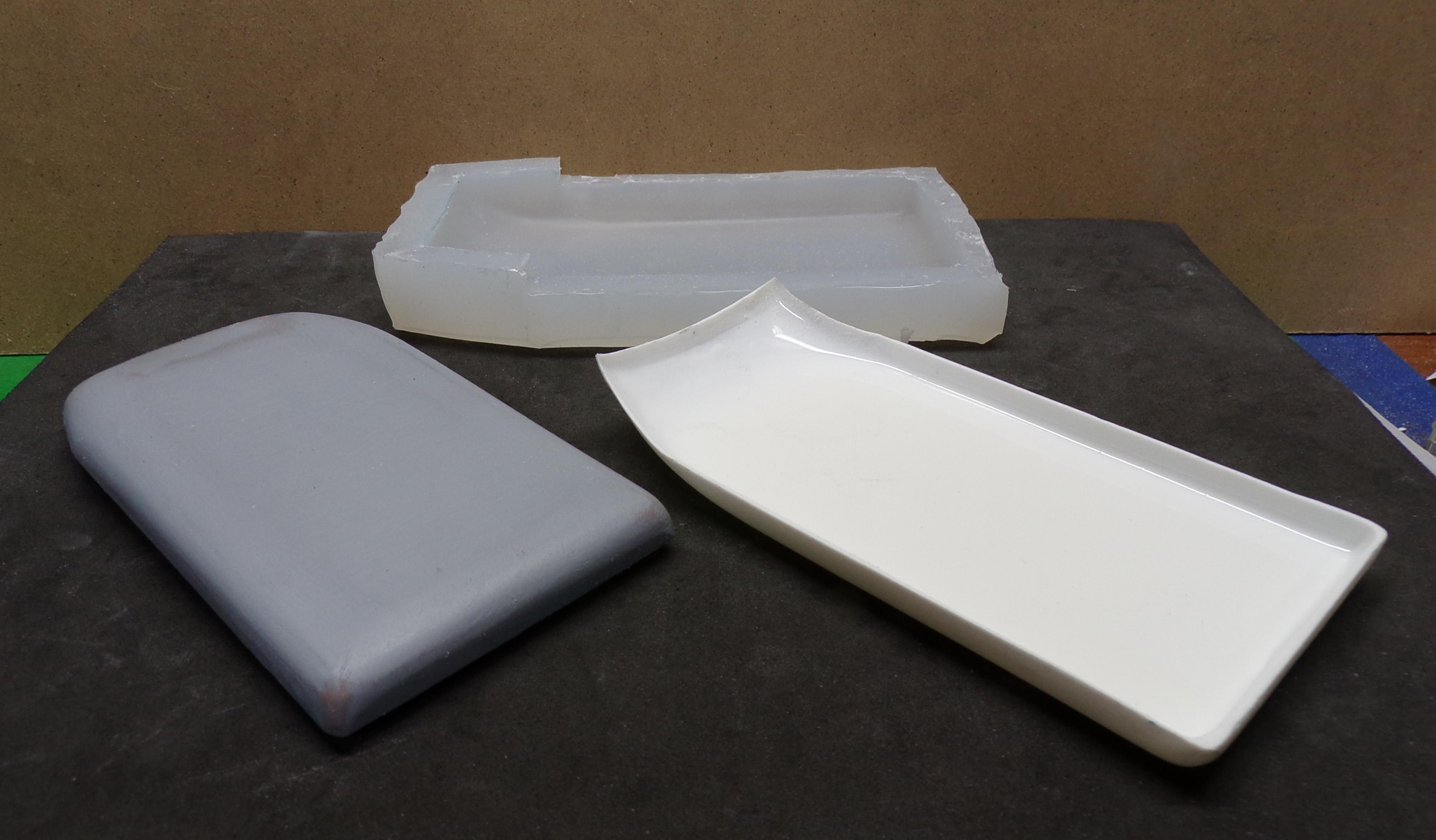
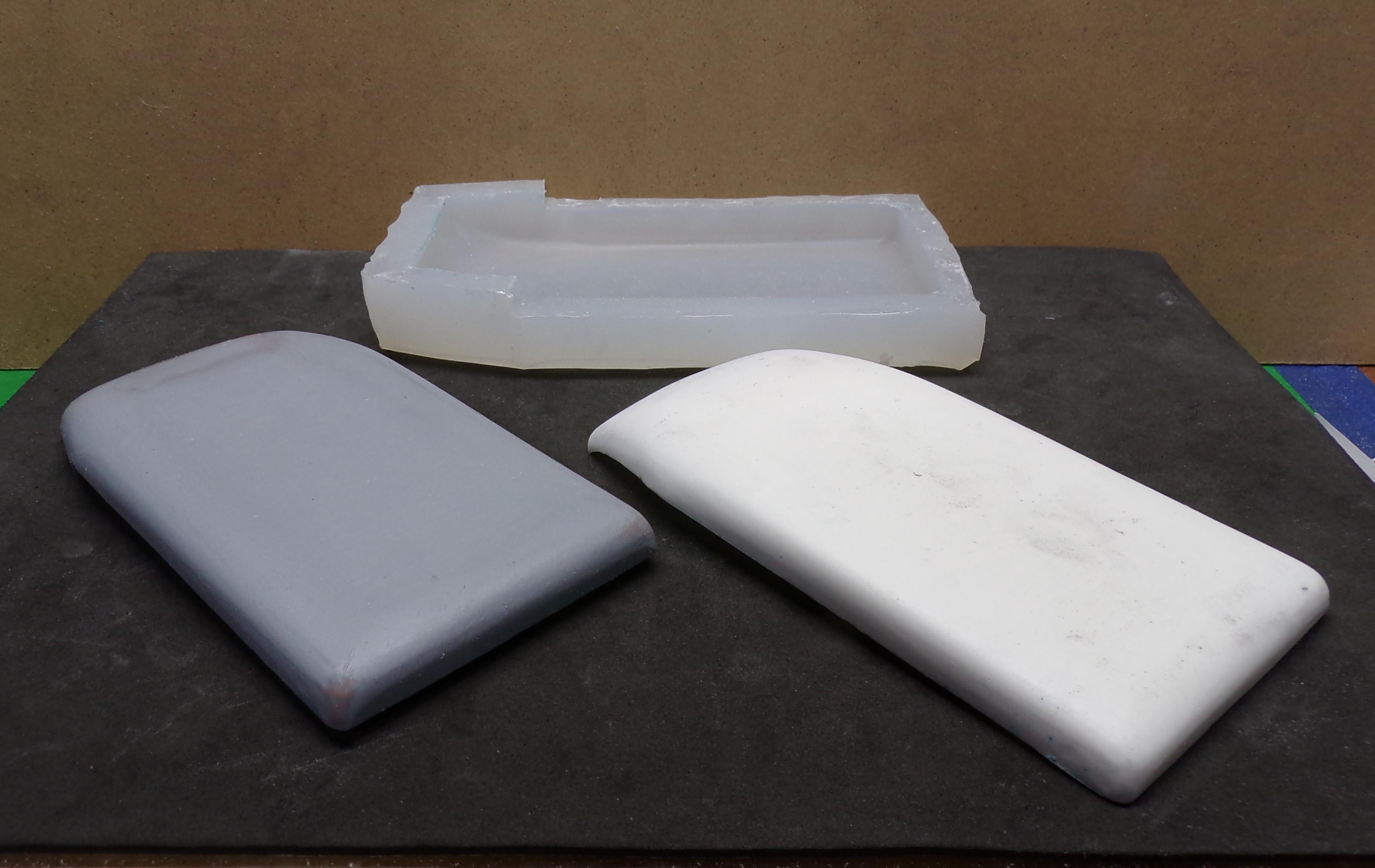
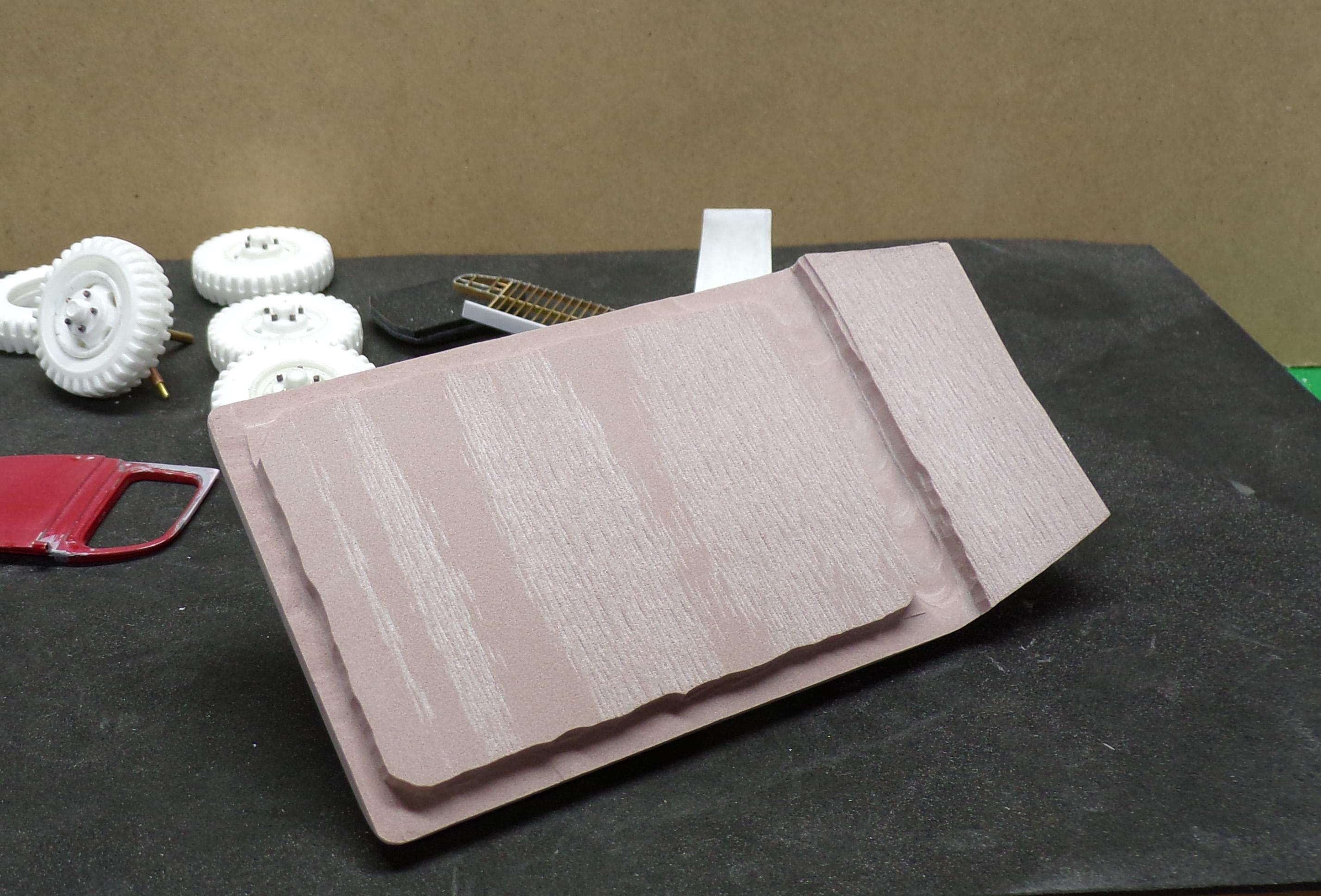
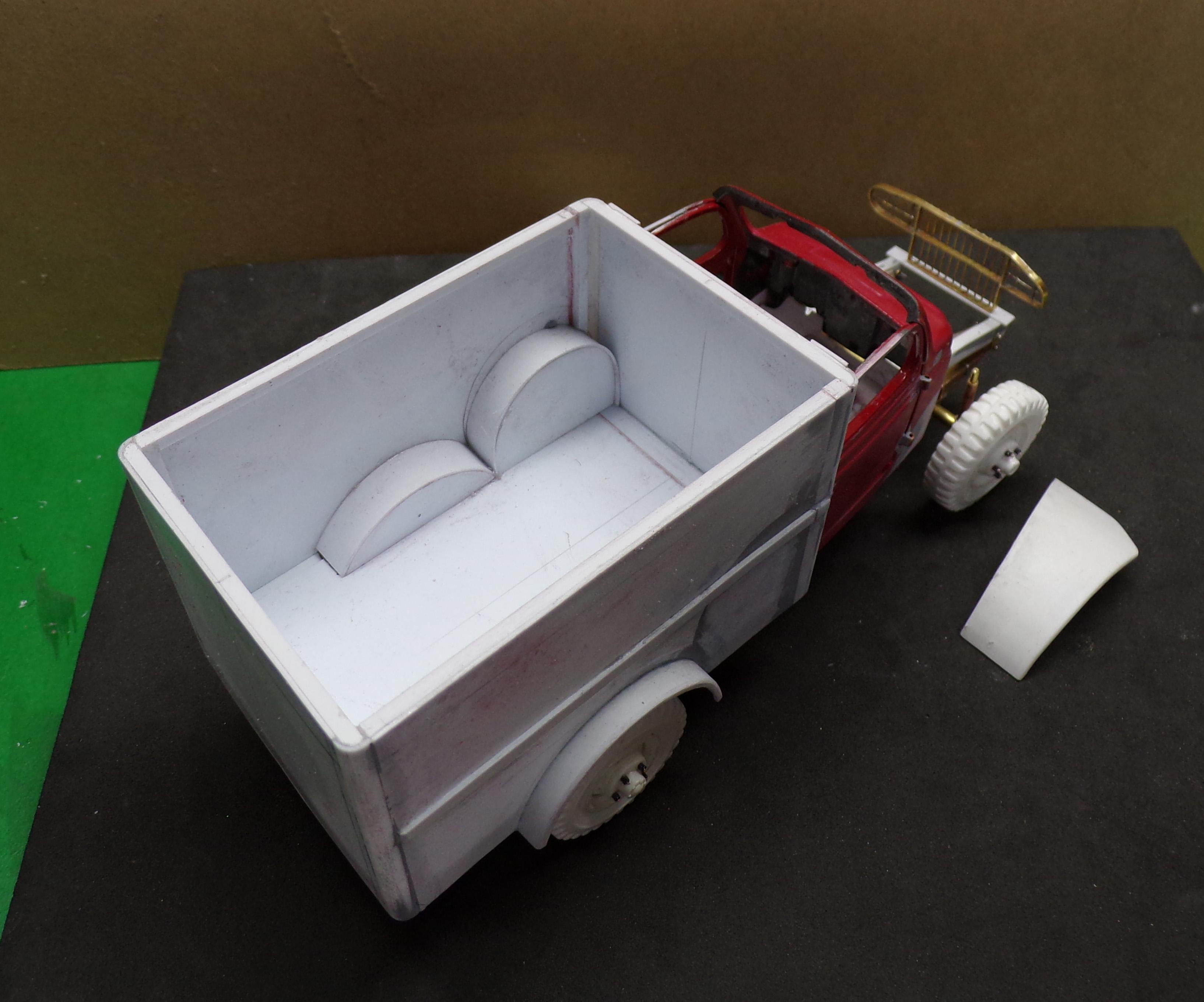
Today I made a slush mold and cast a top for the WC-54. The Renshape top was used as a master. After the mold set up I poured in some two part casting resin and sloshed it around the surface. It took about 5 such applications to completely get the sides to a reasonable thickness but now the interior has the shape of the outside and I can detail the interior of the body.
-
Good old Renshape! What you see will become a master for a slush mold for the top. Ta Da Dit Da Ta Ta Ta... Ta Da Dit Da Oh Oh Oh...🤣
-
You're welcome, Mark! 😆 I know you can do it! 😎
-
Not too much of a chore. The outside of the guard was bent to shape first. Then the bottom and two sides next. They were then soldered together. The individual vertical pieces and those in front of the headlights were individually placed using a template laid down on a flat surface. A hot iron was used to coat the edges with solder so that the brass wire would adhere. It took a while but was easy to do.
-
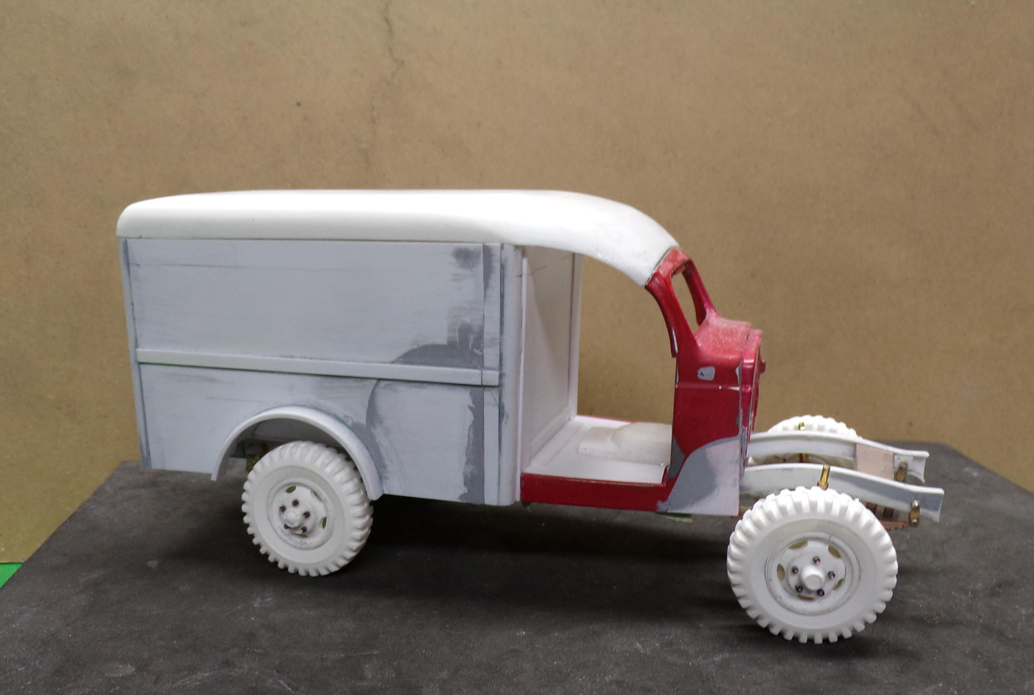
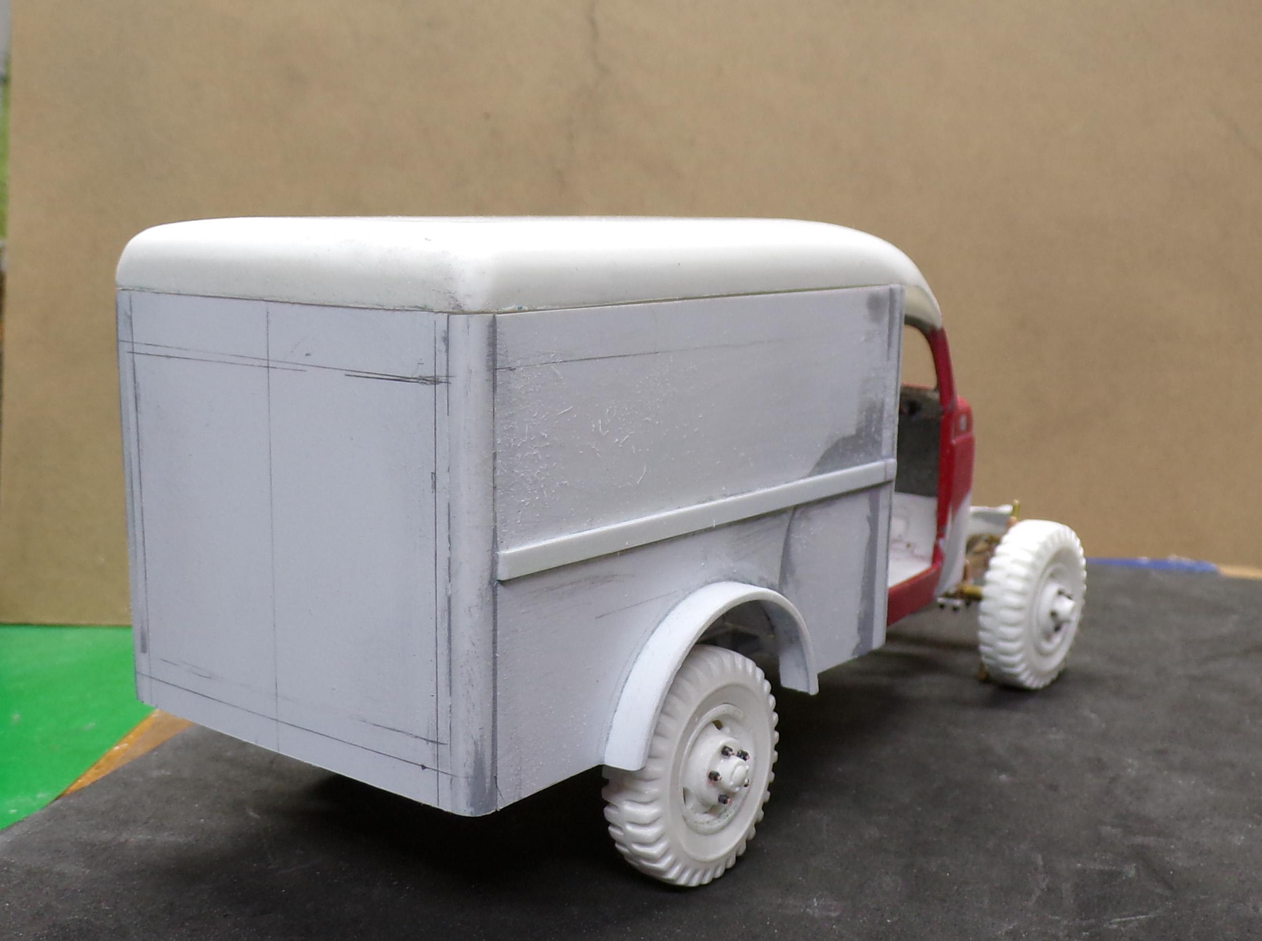
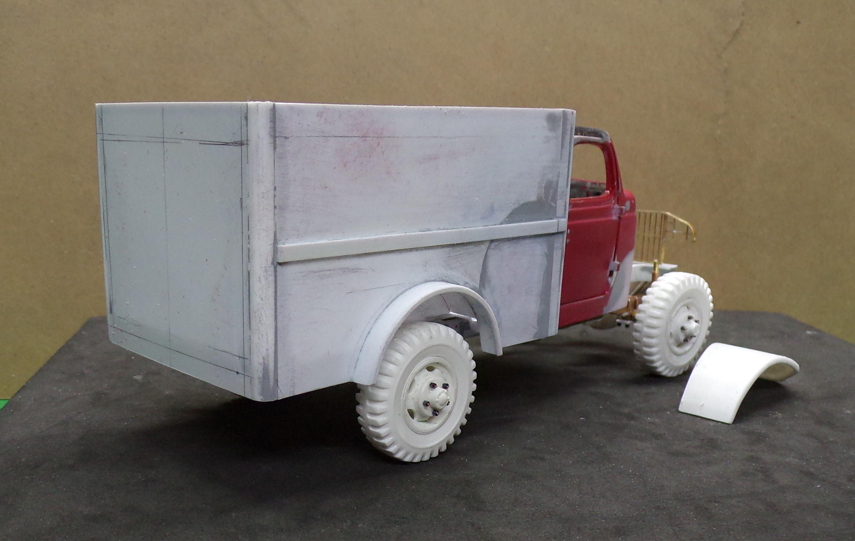
Been working on this for a while. Lots of little things to adjust a long the way. I found that the line drawings are not that reliable regarding shape. The dimensions don't always measure out right. For example it says that the total height is just over 90". Taking away the height of the ventilator shroud it is about 86". But the drawing does not scale, even when the image is adjusted for the correct wheel base. It is what it is, however. I'm working with a diecast cab as well and that accounts for some of the inaccuracy. The rounded top will be a challenge to get right. Right now thinking is that it will be shaped on the outside to fit and then to make a slush mold for it so that the inside will be thin like what is in the photos. We'll see.
-
That's pretty good kit bashing and scratch building. It looks like the windshield is slightly curved. Will you attempt to create this as well?
-
I have a small butane torch and an iron that has an adjustable heat control. Both are useful and at the same time have their limitations. It has been a lot of fun getting to know how to use them as it opened up a lot of building possibilities that I would have not seen otherwise. Brass work can really come out nice and clean to represent certain parts of a model where that clean detail is really important. One example is the brass steering knuckles shown on the photos. Will visit the local hobby shop on Tuesday, however, to replenish my supply of Evergreen. More sheet and strip stock are needed for the build.
-
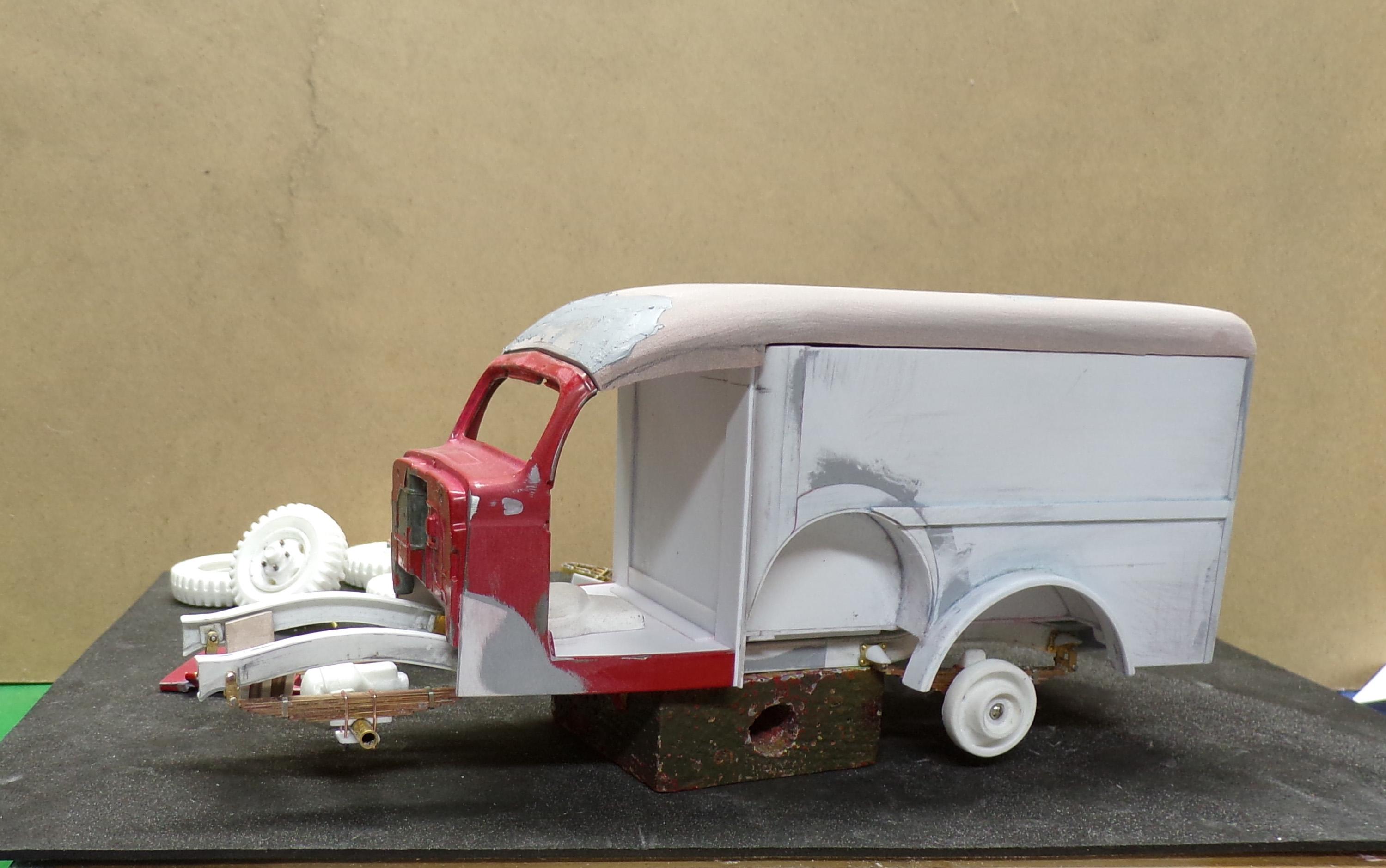
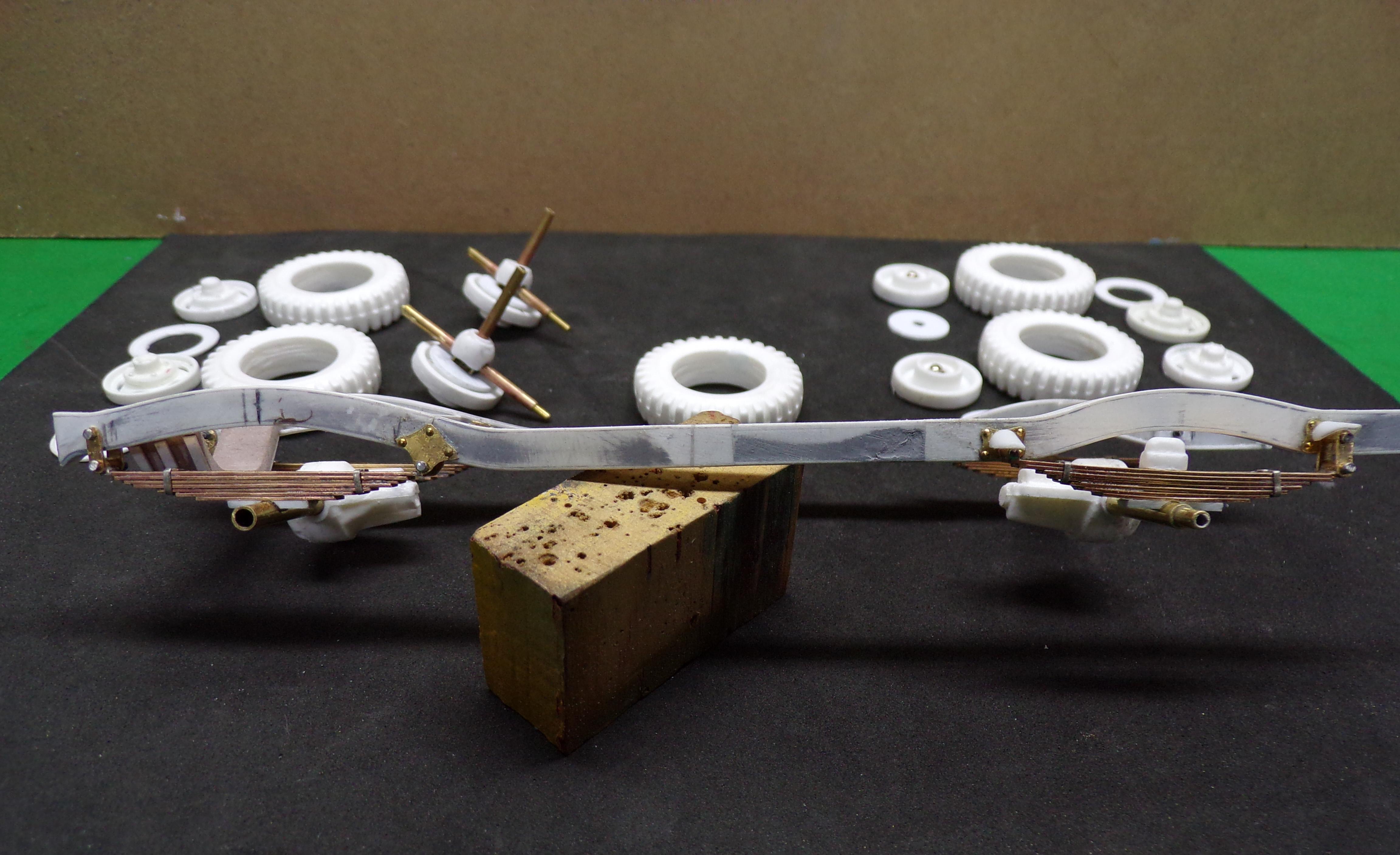
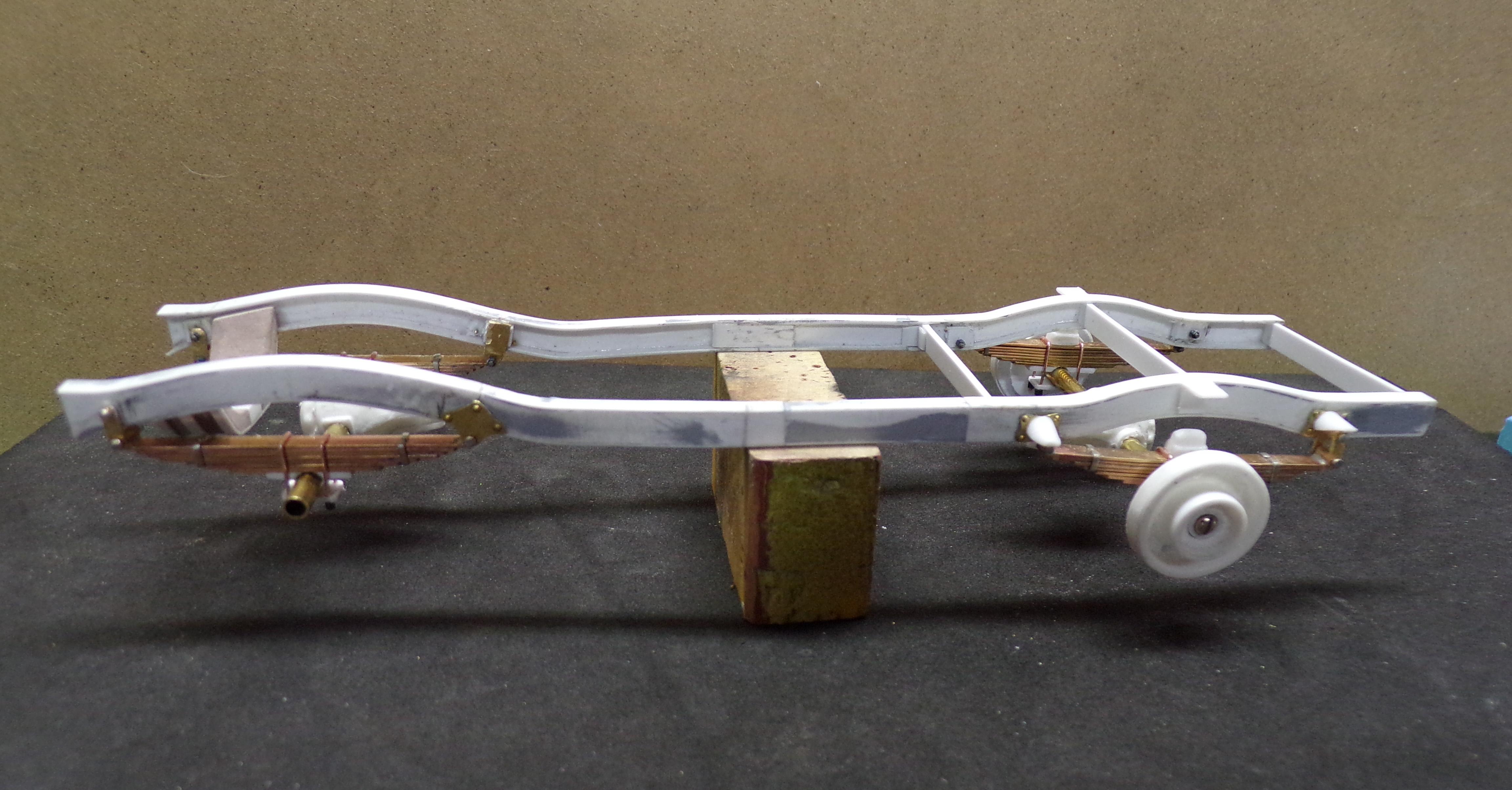
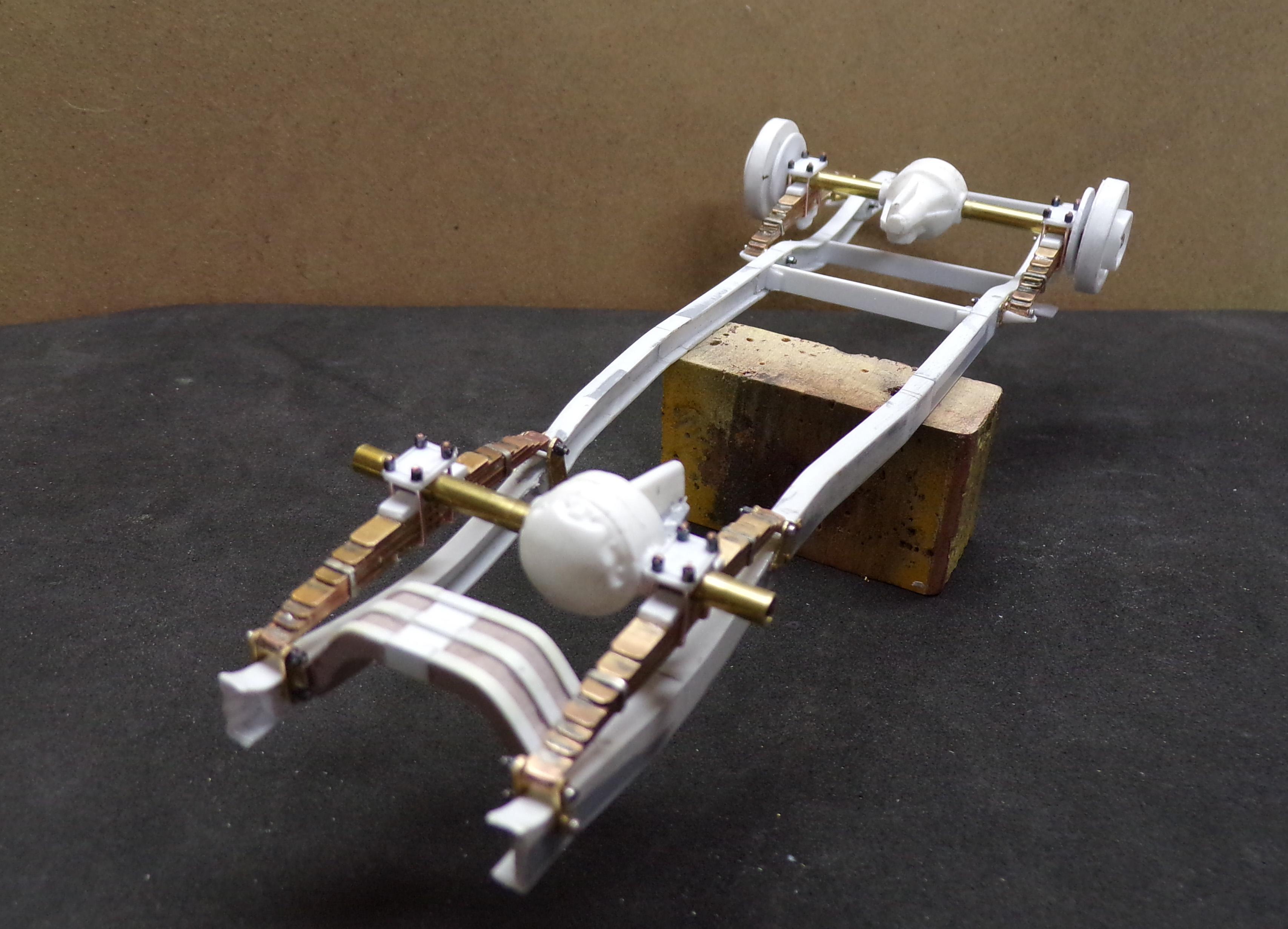
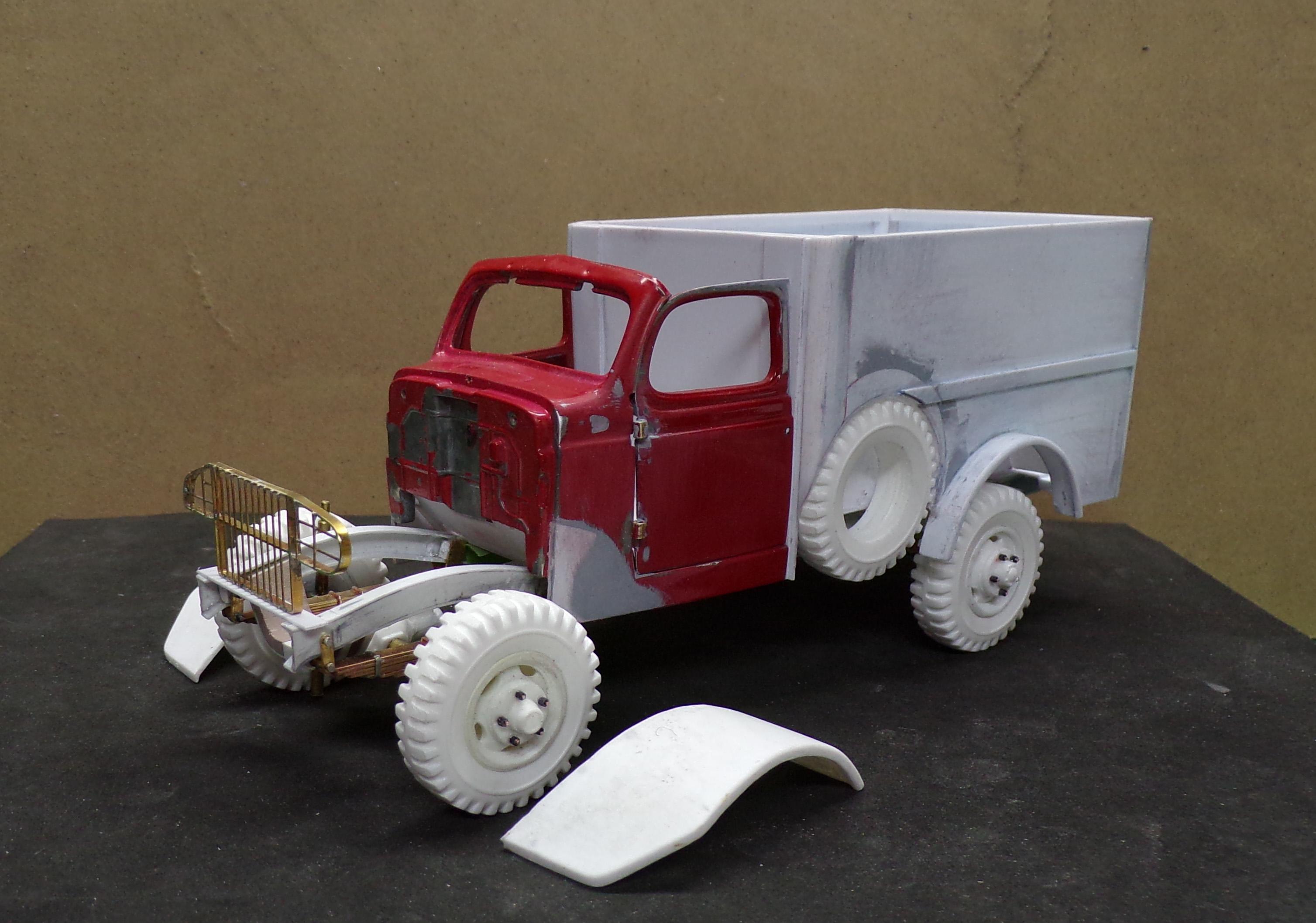
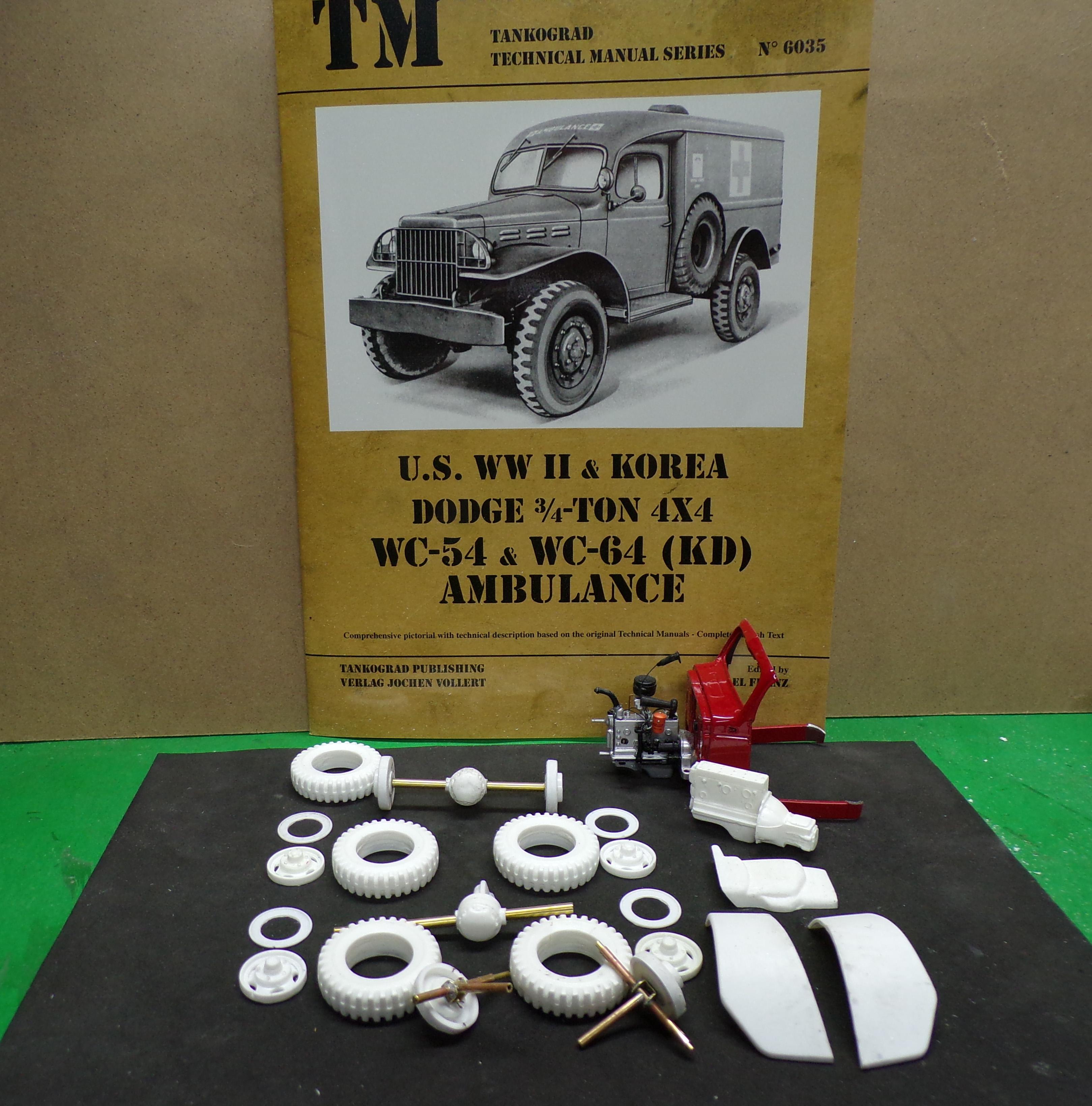
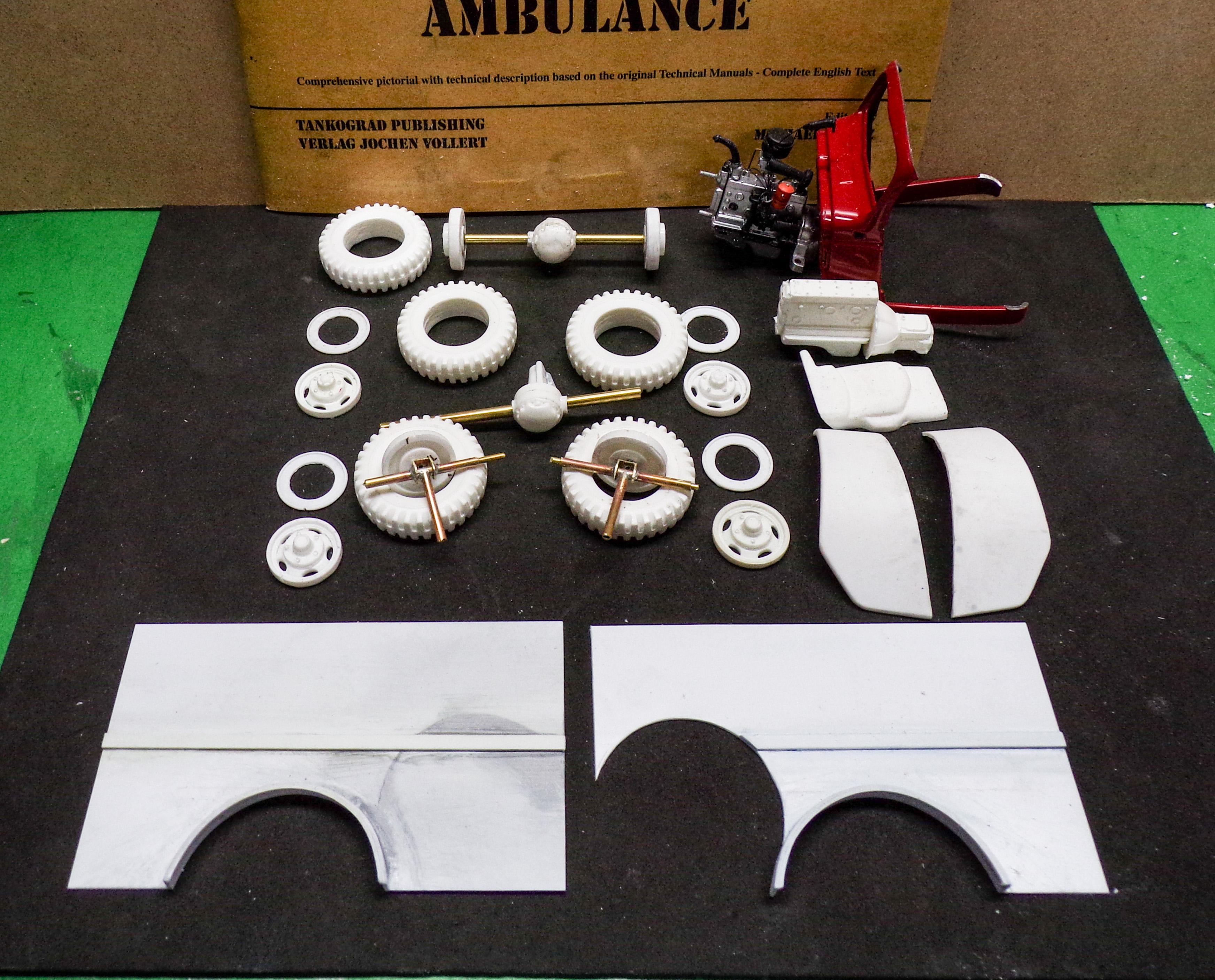
With the Chevy Suburban done I wanted to get back to one more military vehicle that would have been used with the Red Ball Express during WW II. The WC-54 Ambulance is what I have in mind. It is not a soft top truck but is built on a 3/4 ton Dodge chassis with a metal cab that is heavily modified. So far I have made a bunch of castings since the front of the ambulance is exactly the same as the WC -52 and WC-63 which I have already done. So here is the collection of goods that will begin the build. The red cab in the back is a former 1/25 Dodge pickup and the engine in front of it is the same T214 that was used in most of the WC series. Tires are 9:00x20's. The axles are done and the steering knuckles have been made of brass and tube stock, both square and round. Front fenders are castings as are all of the white pieces you see in the photo. Those were made previously from Renshape masters and then cast. The two pieces in the the foreground are the sides to the box that is behind the cab. The extra cutout in the one on the right is for the spare tire. I did the same to the right side one but that was a mistake and had to fill it back in. Oh, well. "Misteaks" happen! Now I need to get some material to make the frame. Brass is an option but I need to select a good piece for the web to solder the flanges to.
- 27 replies
-
- 12
-

-

-
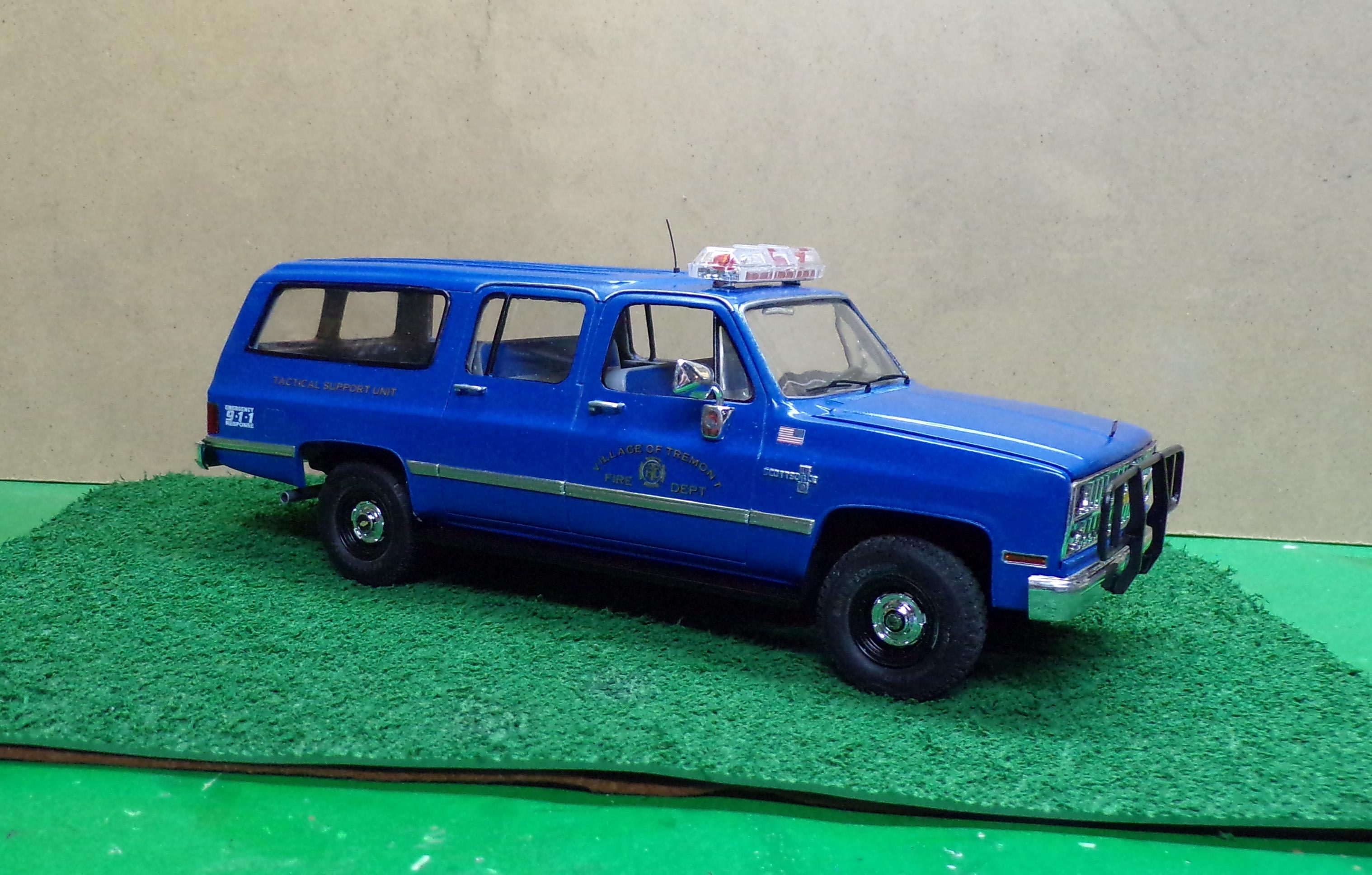
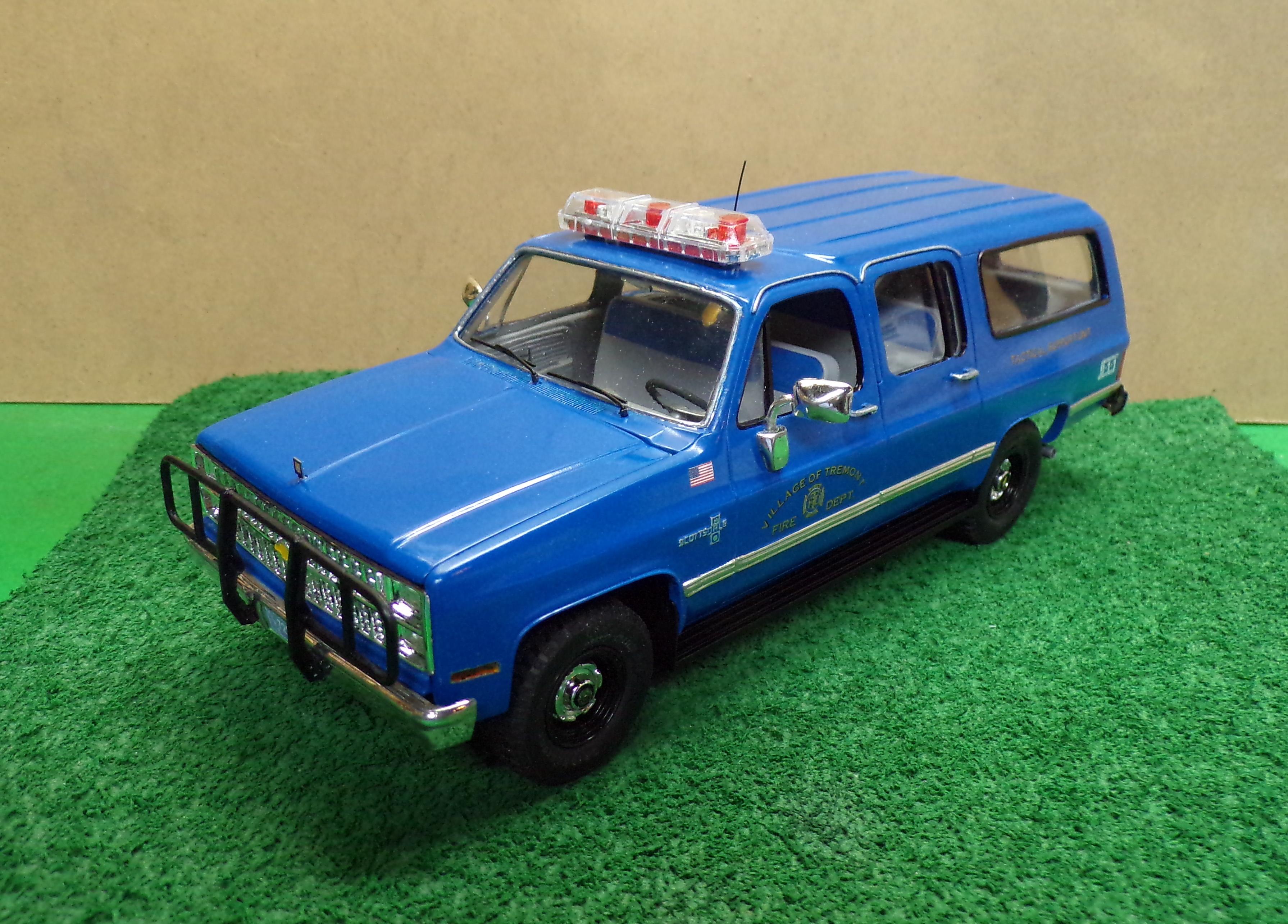
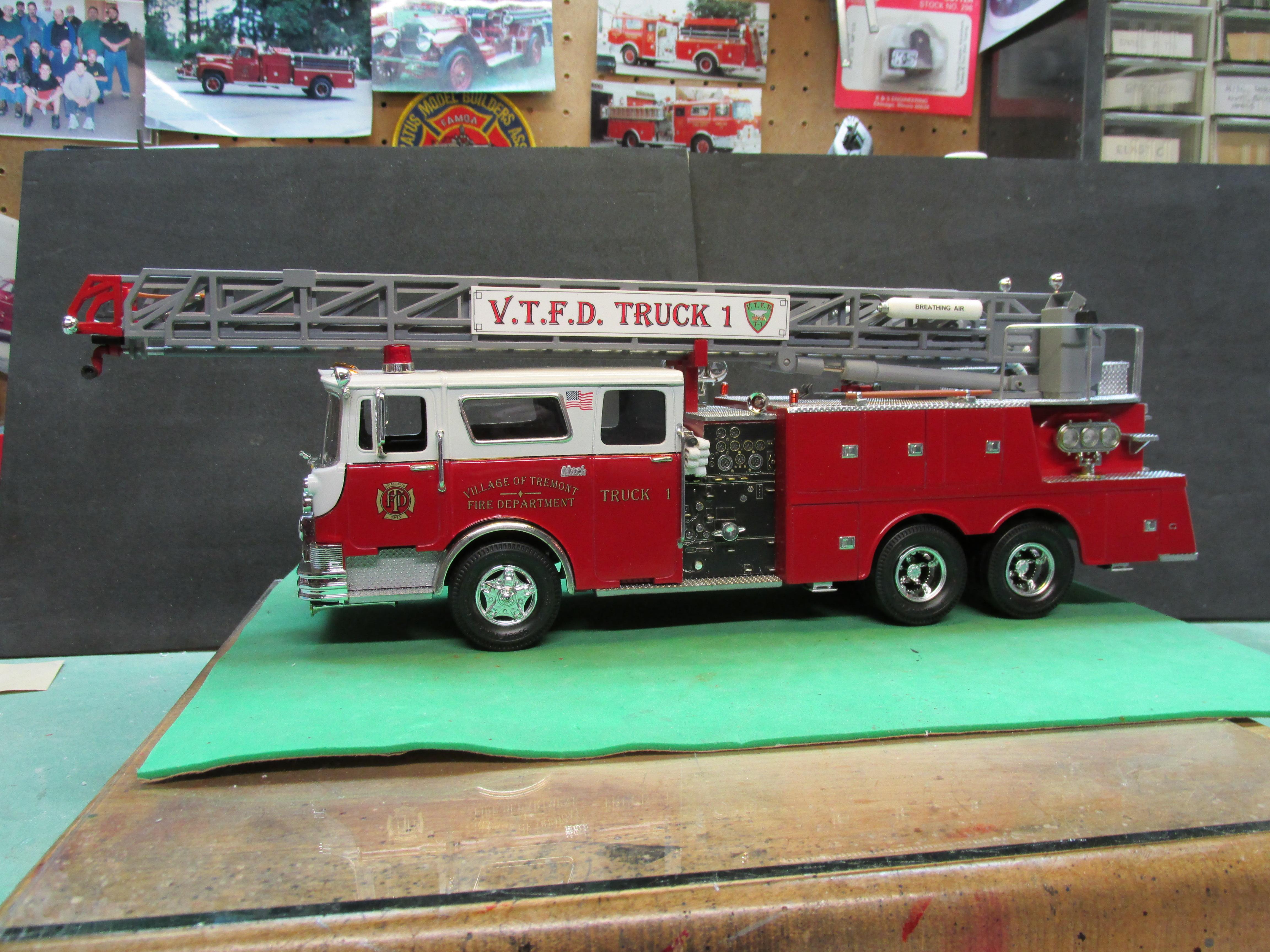
Had this in the stash for a while. The body is a resin casting. Came with an assortment of parts so I picked some of the best and put together a new rig for the Village of Tremont FD. The fleet is growing from an initial Reo rescue to an IH pumper and now a Tactical Support Unit.
- 11 replies
-
- 16
-
-
-
New To The Model Car Community.
Chariots of Fire replied to kram63's topic in Welcome! Introduce Yourself
I build trucks as a rule but I agree with the above sentiments concerning the model you posted. Leave it as is and as one you purchased. Start with the basics of modeling and you will learn as you go. No one ever started building perfect models and no one ever does. There is always a flaw here and there that you wish was not. Nevertheless it is worth exploring and the ideas are numerous. Anyone here would be willing to assist as you might encounter a question or two. Sing out and let us help. By the way, welcome to the board! -
Welcome aboard, Bertrand. Look forward to seeing some of your work!
-
I've had bleed through issues in the past. IMHO it has to do with the plastic and not the paint. I have primed red plastic with Duplicolor gray primer on some red plastic with no issue. Next time around on an other kit of the same model and the red bleeds through. Same with yellow plastic when trying to apply white color coats. Really a pain when it happens. I found the issue to be really bad with the Monogram 1/32 scale CF Mack kits. I put to cabs together using the same color plastic and on one half the yellow bled through. On the other half it did not. Weird! Took using 3 different cabs until I found two that I could join that did not have the bleed through problem. Here's the final result of the join after priming.
-
De-snapping
Chariots of Fire replied to Rockford's topic in WIP: Model Trucks: Big Rigs and Heavy Equipment
A beautiful way of expressing the old adage: where there's a will there's a way. So it took some scouting out the right materials, it took some study and perseverance to shape the inserts, and it took patience to get a stunning result. That is the essence of scratch building and using the talent our Creator has given us. A fine piece of work and an example to young builders everywhere! -
I've kept a time log for most of my scratch build projects. Included are brief descriptions of the work done and when necessary a sketch is included to show the most detailed things. Like Stephen I only build one thing at a time. For me doing the detail things is a reward in itself so it doesn't matter how much time it takes. I have built one type of truck 3 times and although the outside looks the same, some of the details on each one are a bit different because I didn't keep track of the process. No mind though, and I got them all done.😎
-
possible source for Ford Engine Blue
Chariots of Fire replied to fiatboy's topic in Tips, Tricks, and Tutorials
Auto Zone carries VHT Ford bright blue engine paint. Just bought some.